


Rick01
-
Posts
652 -
Joined
-
Last visited
Content Type
Profiles
Forums
Gallery
Events
Everything posted by Rick01
-
Is it possible to tighten them a little? I know it's pretty labour intensive but the end result is worth the time. Rick
-
No fool like an old left handed fool
Rick01 replied to Don Case's topic in Modeling tools and Workshop Equipment
Don't know about that but the kids won't use my hand saws, nor my hammer. They swear that they all have a slight left bias which is probably correct when you think about it! Rick -
No fool like an old left handed fool
Rick01 replied to Don Case's topic in Modeling tools and Workshop Equipment
I know the problem all to well. Any sort of electrical saw can be a nightmare! Rick -
I gave up on the rigging instructions fairly early on, grabbed my copy of "Rigging period fore and aft craft", followed the American Schooner illustrations and also found as many photos of the replica as I could to help work from. Rick
- 92 replies
-
- 1
-

-
- artesania latina
- le renard
- (and 1 more)
-
Did you glue the mast in place? I've always left mine "free" and that's allowed a certain amount of adjustments to rigging tension. One thing I've noticed, the foot ropes for the main spar look to be hanging a little low. Remember that these would only be low enough for a man using them to lean over the spar at the waist, so really probably scaled down from around 1 metre. Rick
-
If you're spacing them around 1 cm apart then you.ve only another 54 to go and around 200 + knots (depending on how many need re-tying! 😉 I usually manage around 10 ratlines each session, then my shoulders and eyes start protesting. Looking good. Rick
- 92 replies
-
- 1
-

-
- artesania latina
- le renard
- (and 1 more)
-
The beauty of the first planking is that you can stuff it up pretty badly and still get away with it with careful sanding and filling. Additionally using PVA glue it's not impossible to remove some planking if it goes horribly wrong. With one of mine I had to strip nearly half off one side, it had just got a mind of its own! It's a learning curve and first planking is a pretty good exercise, just treat it as that and take your time. Rick
- 18 replies
-
- 1
-
-
- Lady Nelson
- Amati
- (and 2 more)
-
Can't go past this advice for a good build. I took around 8 months to complete mine, I didn't complete a build log at that time I'm afraid so no pictures.
- 8 replies
-
- 1
-
-
- first build
- lady nelson
- (and 2 more)
-
Remember when doing research that this is not a model of an actual cutter, but a representation of cutters in general. This allows you more scope in finishing. It's a nice model and fun to build. Rick
- 8 replies
-
- 1
-
-
- first build
- lady nelson
- (and 2 more)
-
No - part of the reason for the rabbet it to take the first layer, as I mentioned this will then provide a smooth run and with 2nd planking at .6mm it will all fall in place neatly. You do need that area to taper off smoothly and at the moment you have a bit of a hump there, if you don't want to try removing and re seating then a bit of judicious sanding should work. Rick
-
You should also have taken those first two planks right up to the stern post, otherwise you'll have a nasty lump instead of a smooth run to the keel and stern post.It's not too late to CAREFULLY remove those two plank and replace with one's running the full length of the ship. I know they'll be slightly damaged but the can still be used elsewhere. Rick
-
Figure 4 almost has it.This is a light weight yard and as such, I'v a lift going from the yard tip, up through a block lashed to the mast then down to a belaying pin on the pin rail surrounding the mast (obviously this refers to each side). Which pin you use is dictated by ensuring the halyard doesn't chafe on any other lines. Rick
-
No worries - glad to help here. As this isn't a model of a specific cutter feel free to make any variations you want, it does make a pleasant little kit. Rick
-
I don't know if it's due to the photography or not, but it does seem to have a slight longitudinal curve. Noticeable in the first side shot and last head-on shot. If so, at this stage packing out a filler on the inner side of the curve should be enough to fix it. I run a steel straight edge along the keel when I check mine as I fit any fillers. Basically how I handled mine, I also fitted these items before planking, not after as the instructions indicate. Rick
- 18 replies
-
- 1
-

-
- Lady Nelson
- Amati
- (and 2 more)
-
I usually temporarily fit the mast so that I can drop a couple of lines down to simulate shrouds, then I can line the chains and dead eyes up correctly. Also, for future reference fit the chains then add the reinforcing strips, it does save these problems. Rick
- 92 replies
-
- 1
-
-
- artesania latina
- le renard
- (and 1 more)
-
We've all done something similar at least once!! Rick
-
Bilge pumps! Needed as much as water barrels 😉 I sat mine where you've got the barrels but there's plenty of room just aft of the barrels for two pumps. Great representation of the cutter. 😊 Rick
-
I keep a small supply of .5, .6 & .7 mm drills. All cheap Chinese but for the amount of time I need them (and break them) they work fine. I see you've beefed up the davits etc. as well. Or were they supplied in the kit in that thickness? Making good progress now. Rick
-
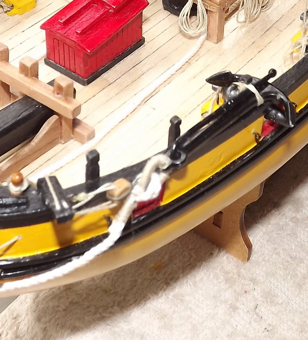
Much better (and stable) stand, plus doubling the thickness of the other components gives a more realistic look to the kit. You only going with the one anchor? I did purchase a second one and have rigged them slightly differently. Rick
- 110 replies
-
- 2
-
-
- le renard
- artesania latina
- (and 1 more)
-
When you do get this far, consider placing a yoke on the cross bar. Currently there is no support for the boom when the sail is not hoist, this seems to me an obvious place for a "rest" and that's the way I worked. There is a photo out there showing the replica with a rest (removable I assume) on the stern but like a lot of other bits and pieces it seems to be a matter of "best guess" . Rick
-
28 on my version of the ship!! 😄 Rick
-
I lashed all mine. No wire twists used anywhere, I'm afraid I pretty well junked the whole AL rigging plans and used my copy of Petersson's Rigging fore and aft craft. In addition I hunted the net for photos of the current replica to check on how it has actually been rigged as the instructions are really a drastically cut down and basic "looks good" set up. If you check my photo here https://modelshipworld.com/topic/24327-le-renard-by-gaffrig-artesania-latina-scale-150/page/3/ you should be able to see what I've done. Rick
-
You could join this forum and ask for some assistance in locating a Kiwi Hurricane pilot. http://www.rafcommands.com/forum/forum.php The guys there are very helpful and have a wealth of knowledge between them all. Rick
-
Have you decided how you're going to handle the anchor cables? Mine run across the deck and down through the main hatch which needed holes cut in the "grating". Note also only one anchor provided not the two that the original would have carried. Rick
-
Hi Tom - rather than hijack any more of Gafriggs build I'm happy to tell you how I've arranged various items here. I've fought with this kit for eight months now and have decided that I'll claim it as my "representation" of the original given that the plans really only follow the replica not the original. Looking good so far. Rick
