Rick01
-
Posts
652 -
Joined
-
Last visited
Content Type
Profiles
Forums
Gallery
Events
Everything posted by Rick01
-
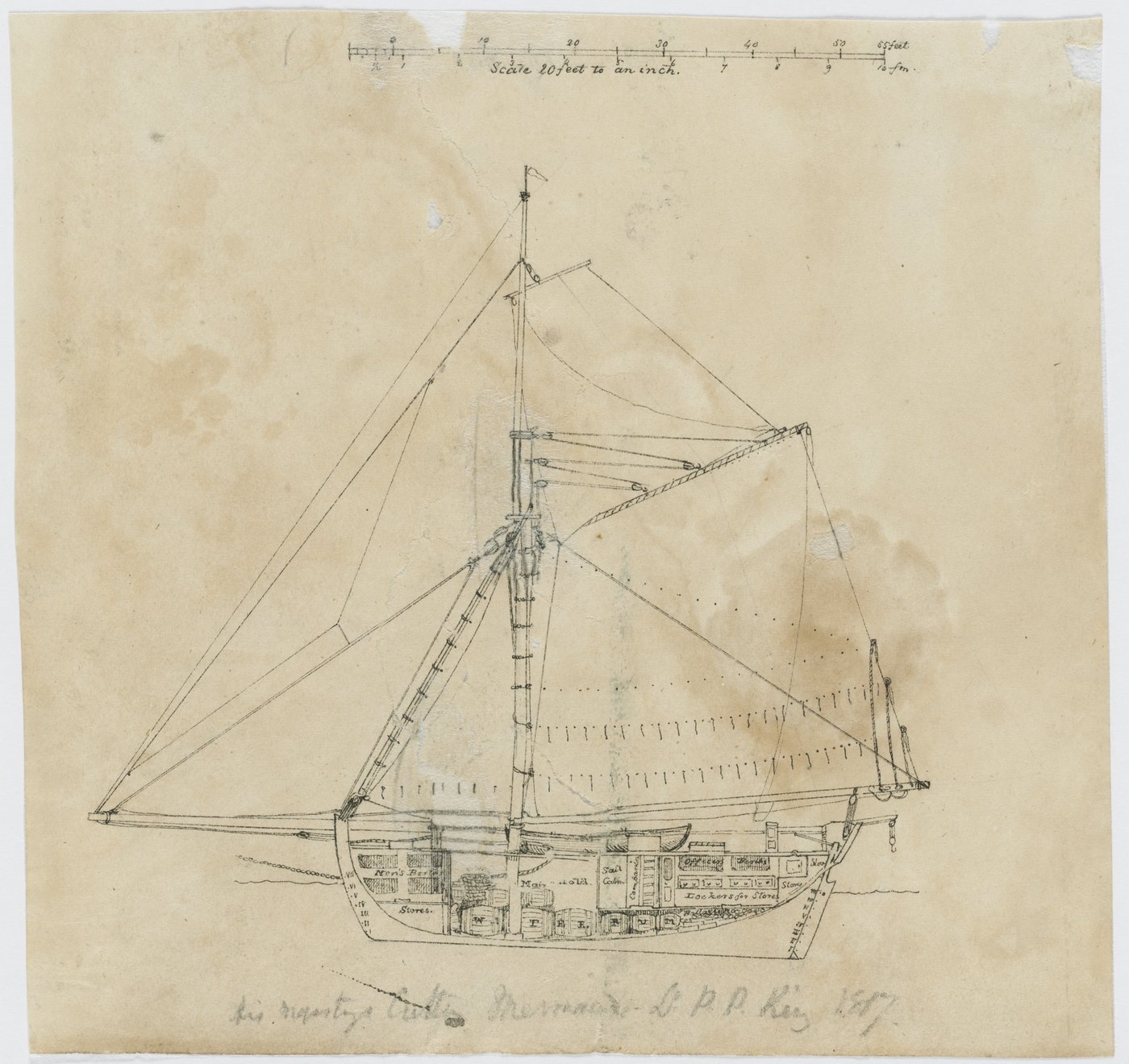
Hi - I've built one ship from Modellers Shipyard, HM Cutter Mermaid. Ideal for you with it's Australian history, regretfully it's not the most accurate kit given how much information is out there but there are a number of good builds on this forum that detail this little cutter well and it's not at all hard to alter the kit slightly to become a truer model. It was my second build and I found it straight forward and gave a pleasing result. Rick
-
If you check the companionway here you can get an approximation of the side profile and it should really only be wide enough for a man to get down the steps/ladder. It looks as if the binnacle here has a slightly sloped top and the compass and oil lamps at the top. Rick

-
Don't know if you've found this site http://renard.dechorgnat.com/index.html which covers some of the errors that appear in both the Soclaine and AL kits. Also there is no windlass and the anchor cable appears to go into the hull rather than onto the deck then down to the rope locker via a windlass. There wouldn't be room for a windlass below decks on a cutter so hoisting the anchor via a windlass or by hand appear to be the only option. Another possible error is with the siting of the various deck furnishings. Coming forward from the stern there's an item that may or may not be the binnacle housing for the compass almost directly after that is a companionway. These are sited so close together on the plan that you would not be able to open the doors on the companionway fully, in addition the binnacle is fixed to the deck but my understanding is that it would be lashed down and could then be stored below decks during any action. In fact the AL kit seems to be a copy of the replica with its amendments to comply with current regulations not of the original. Rick
- 110 replies
-
- 1
-

-
- le renard
- artesania latina
- (and 1 more)
-
I've always used a dilute PVA glue on knots, likewise a very dilute solution used to soak the flags allows you to move them into any position you want. This is best experimented with beforehand to get the correct solution - sorry but I can't remember the ratios! Rick
-
Have you looked around at previous builds of this model. There's a very good one by Vossiewulf ( although unfinished) that would be worth your while looking at. Easy way to hold the false deck down it using a number of heavy duty rubber bands. Rick
- 11 replies
-
- 1
-
-
- lady nelson
- amati
- (and 1 more)
-
Literally just started this kit a week back although I haven't started a build here. It seems to be a fairly accurate model of the replica rather than the original as far as I can tell. Instructions are not the best either! It'll keep me busy but I feel that I'll have a fight most of the way. If you want a cutter and are prepared for a bit of bashing then look at H. M. Cutter Mermaid, there are a few builds here and plenty of historical detail out there to enable you to take the basic kit and turn it into a nice reasonably accurate model. Rick
-
This may not be the case. If you position them that way you effectively block all fore/aft access due to the position of the companionway. When it was carrying a full complement of boats I'd have thought one would be hung off the stern and another two nested one side or the other to allow a speedy movement of crew either port or starboard side. Rick
-
On the cutaway it's pretty clearly half way between the windlass and the bow and would have to be off-set to allow access for the crew. I'm very doubtful about using a grating style as it's not exactly waterproof without some type of cover which would make crew accessing it pretty cumbersome. The one you've illustrated behind the bowsprit is actually an access to the rope locker and you can see the anchor cable going through it. To provide waterproof access I can't see any other option than a sliding hatch given how tight space is in that area. Rick Ps It's funny but I was only thinking of you two a few days back and wondering why you hadn't come back given how well you were both doing!
-
For positioning of the various furniture items you do need to refer back to King's cutaway drawings as the model plans are pretty dismal in that area. I see you appear to be thinking of putting a hatch forward of the windlass - won't work as the bowsprit comes back over that area.🤔 Rick
-
A lot of the plans I checked seemed to tuck the windlass under the bowsprit and braced to the fore of Samson posts. Still looking!! Rick
-
Not that one although that does illustrate the conundrum. Go to the page I tagged then click on 'Support de bout-dehors" this brings up a photo of the actual bowsprit support on the modern Renard. Just checked 70 odd cutter plans on National Maritime Museum from the relevant period and only found one that didn't show a windlass - it was a 43ft cutter captured on Lake Champlain so at that size and in fresh water I doubt the anchor(s) would need anything more that a few hands to pull them up! Rick
-
This page clearly shows the bowsprit support and it's exactly like the AL box illustration! So no help there I'm afraid. http://renard.dechorgnat.com/mature_details.html Looks like more investigation needed yet! Rick
-
Thanks everyone - it confirms my feelings about the windlass. I'll head off to search more photos of the replica and work from your model Frankie plus whatever I find online. As for moving the bowsprit - if a 1 metre pole is put in to the holes either side then a couple of crew get behind them and push I'd expect that it would slide reasonably well. Rick
-
I'm wondering if an arrangement something like this would have been fitted. https://collections.rmg.co.uk/collections/objects/1060511.html It allows the bowsprit to be drawn in above it whilst utilising the bowsprit supports to act as the mount for the pawl. The low access hatch to crew's quarters also clears the retracted bowsprit. This illustration from the box shows that although the cable disappears into the hull there is ample room with some minor adjustments for a windlass and in fact the supports are there with what appears to be a squared beam rather than a drum as I'd expect. Rick
-
I'm contemplating Le Renard (AL) as my next build but am puzzled by one feature (or lack thereof). The anchor cables disappear into the hull at around deck level on the illustrations I've seen but there is no sign of a windlass or capstan on deck. As a cutter of around 68 tonnes would she have had a tween decks capstan? Crew seems to have been 60 so I guess that below decks space would have been at a premium with a rope locker and probably galley stove as well all situated at the fore end of the ship. Comments anyone? Rick
-
Hi Duncan - another relative newbie to this form of torture. I think we all have/had problems with planking but if you take a bit of time to read these articles http://modelshipworldforum.com/ship-model-framing-and-planking-articles.php I think you'll see how it works without too much stress. Really if the end result pleases you that's all that matters and each subsequent model WILL get easier and better. Rick
-
A bit of very dilute PVA glue will get those foot ropes to hang with a nice smooth curve. Rick
- 104 replies
-
- 1
-
-
- sherbourne
- caldercraft
- (and 1 more)
-
But that's what this forum is for. If something is unclear just ask, we all do it even the experts at times. Basically you just need 4 holes drilled at the tip of the arm then rigged through those holes and a block with a hook attached like this. It'll make all the difference if you can manage it. Rick

- 104 replies
-
- 5
-
-
- sherbourne
- caldercraft
- (and 1 more)
-
I've noticed that you don't look as if you're going to rig the cat-heads, is that going to be done when you start on the running rigging? Rick
-
You're correct - the deck will have a fore to aft curve and should also have slight curve centre to port and starboard. You may have a problem with the bulkhead 3rd from the right as its foot is sitting slightly higher than those either side which will mean a dip appearing in the planking. If it isn't already glued I'd drop it a little further then build up the top as it's been sanded down. Rick
-
You may want to consider fixing the shrouds before you do anything else. Tying on the ratlines needs room to manoeuvre either side so items like the stays can really get in the way! Rick
-
I haven't built this particular kit but I'd query the way you've fed the anchor cable under the windlass not over. This would mean that when hauling the anchor in you're actually pushing the bars working the windlass up not pulling them down. All the models I've seen have the cable fed over the windlass. Rick
- 104 replies
-
- 1
-
-
- sherbourne
- caldercraft
- (and 1 more)
-
Bathroom remodelling is the worst!! Been there a couple of times and sworn "never again" each time. 🙂 Rick
-
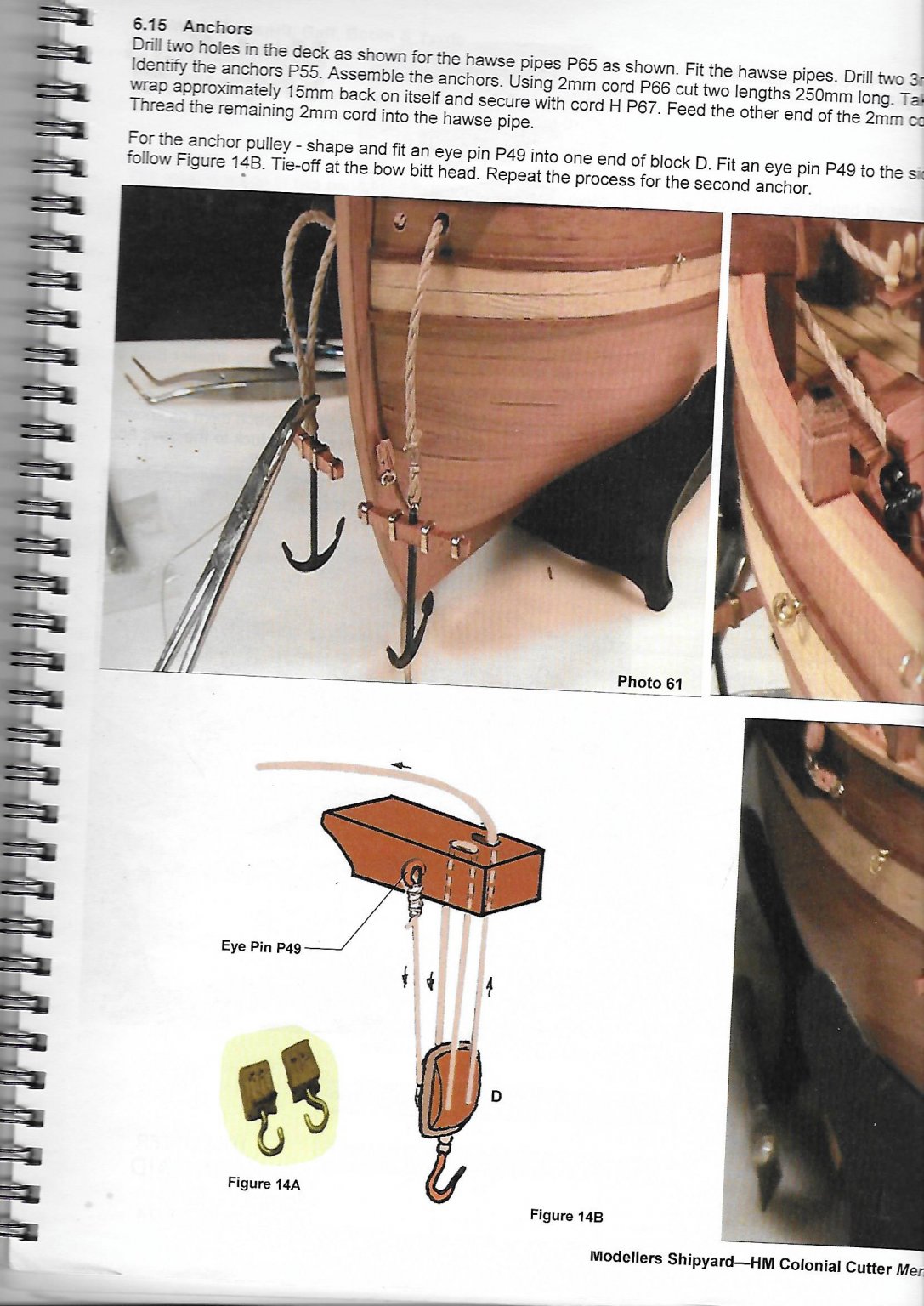
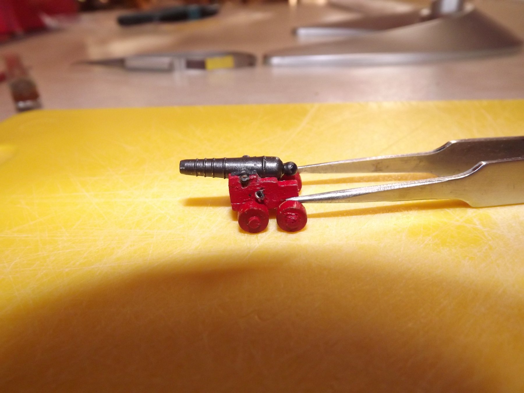
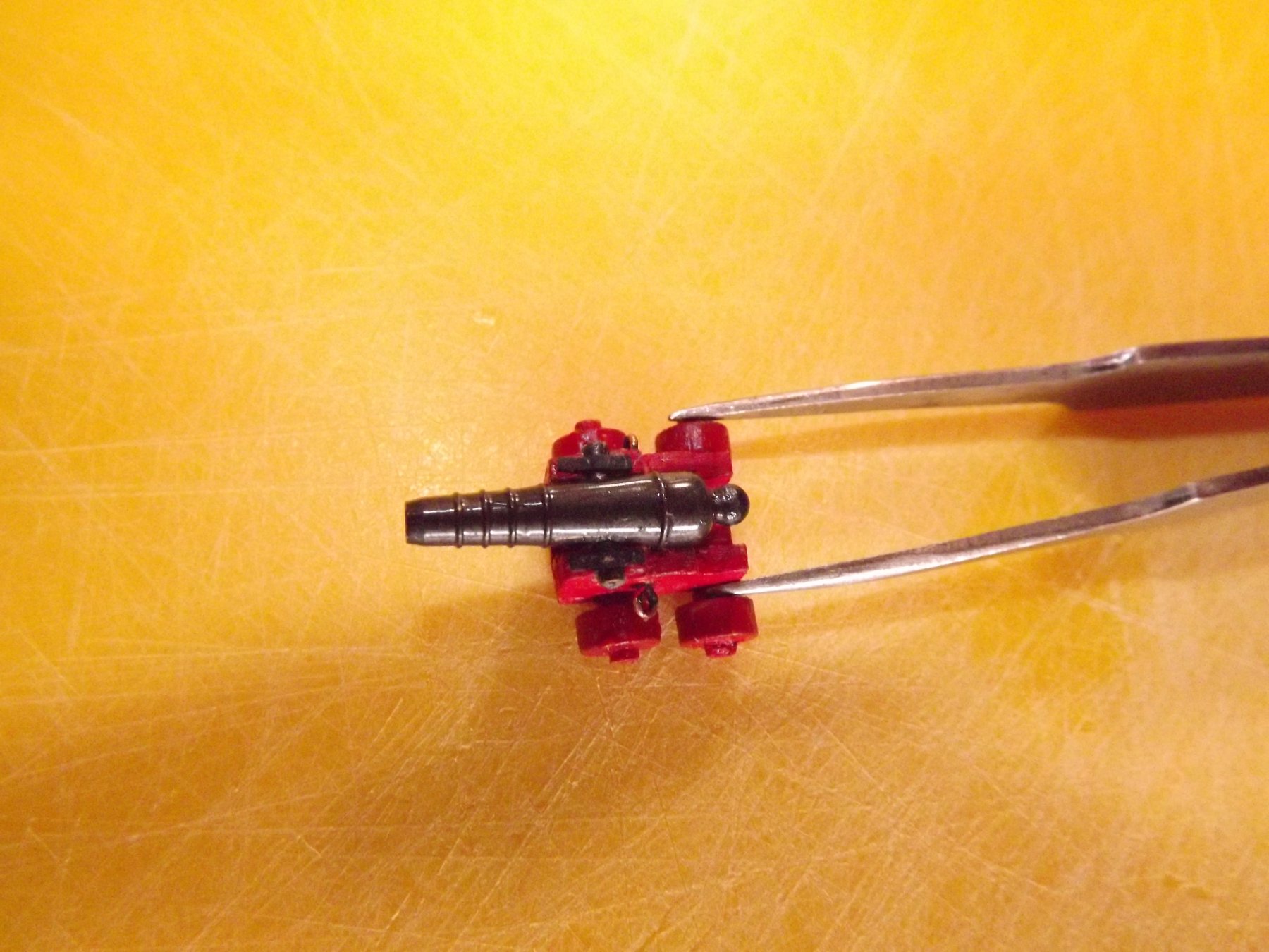
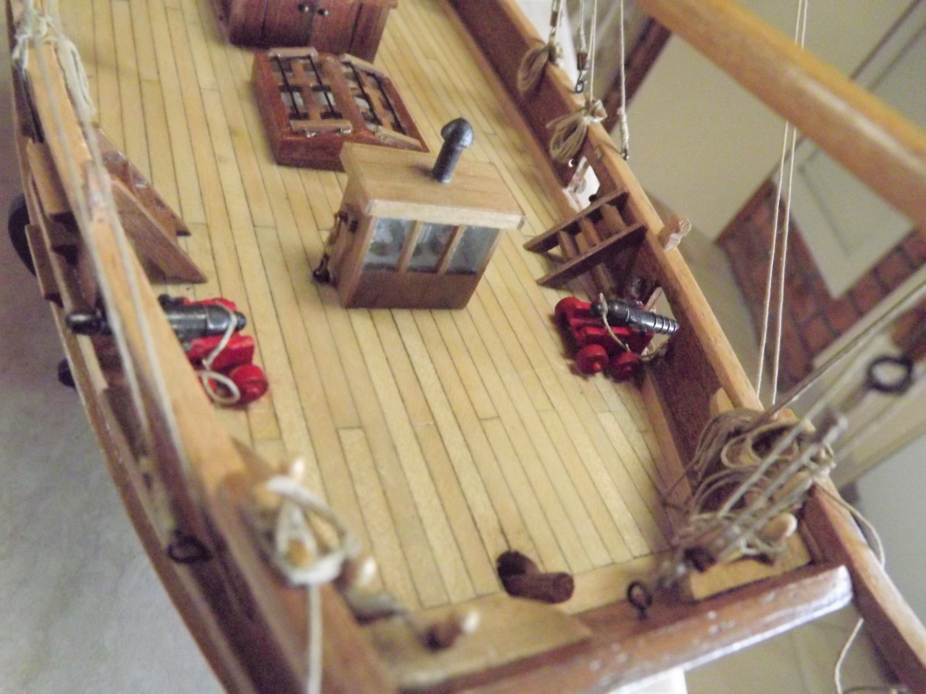
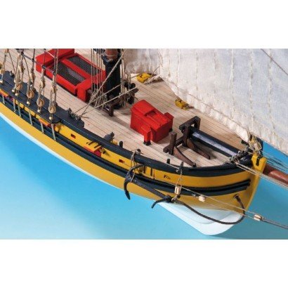
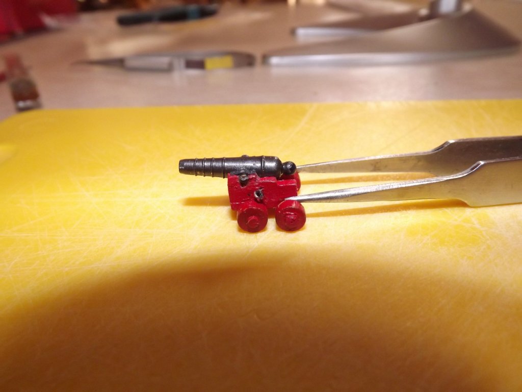
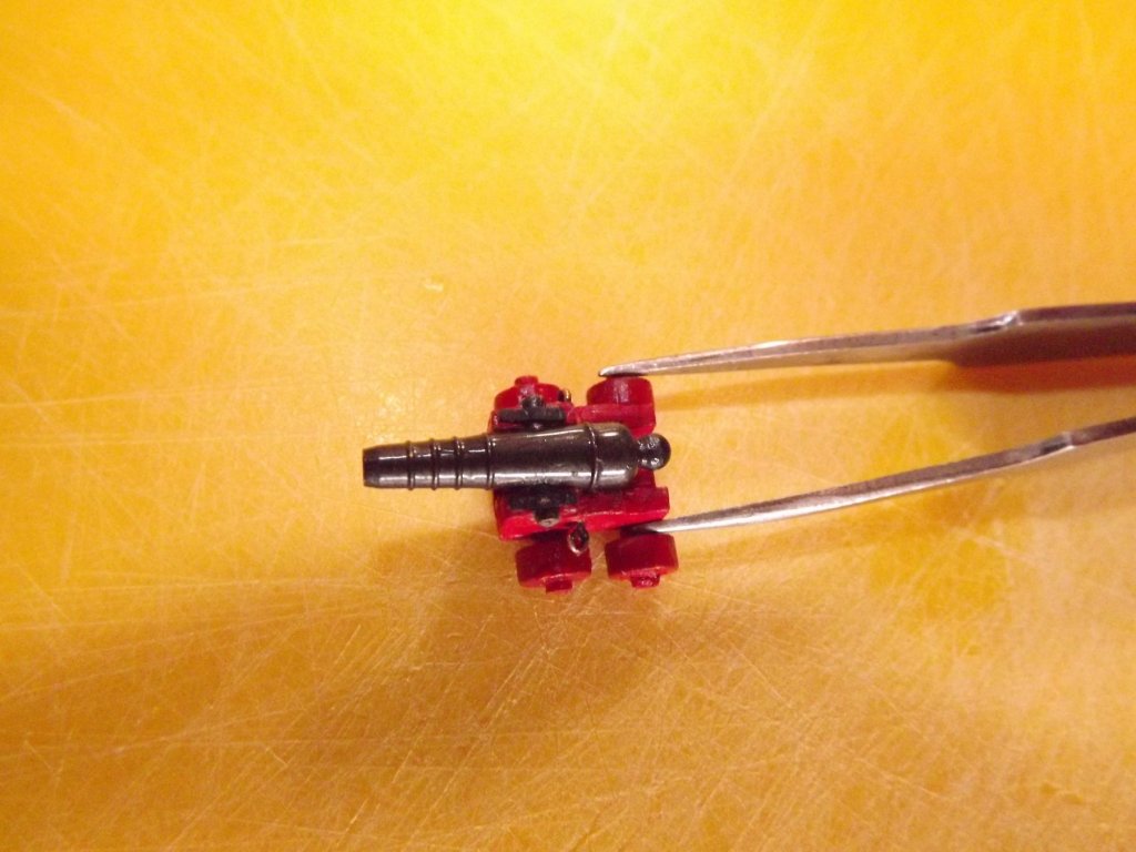
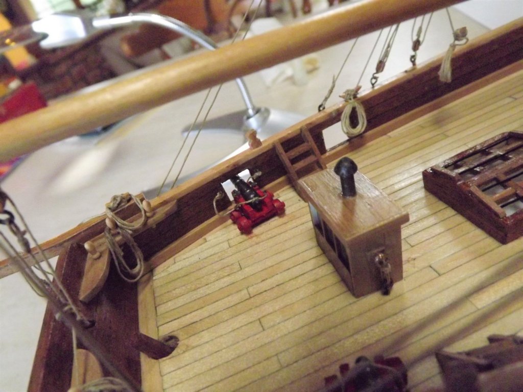
Carronades now fitted to carriages and installed. Purchased from Cornwall Model Boats https://www.cornwallmodelboats.co.uk/cgi-bin/sh000001.pl?WD=carronade&PN=RB-Model-Fittings-Carronade-20mm-RB01123.html#SID=1251 . They had to be amended slightly as the extension on the rear of the barrel just didn't seem right. So this was removed reducing the overall length to 20mm after re-fitting the button, much nearer the 17mm I was hoping for.

- 241 replies
-
- 4
-
-
- mermaid
- modellers shipyard
- (and 1 more)
-
I skipped them deliberately and have been waiting for someone to mention them. I didn't like them from the start, noted that no provision was made for them on the cutaway sketch so queried it on this forum. I was told (can't remember who) that it was quite possible that they in fact had pumps that could be taken down/rigged only when needed. Given that King took the time to show the binnacle which is not a fixture, the ship's boat and the beam in the crews' quarters that is the main support for the windlass I felt that omitting any pumps was a fair assumption. As you say it is crowded although there is space either before the binnacle or just aft of the main hold, but only this spot would allow a pump a straight line access to the deepest part of the holds. If you do go with them I'd guess around 12~15 mm would work as a reasonable size. Glass - I scrounged some 2 mm glass from a local glazier but went for white card under. Still gives the impression of a void but (to me) isn't quite so "in your face". 🙂
- 241 replies
-
- 1
-
-
- mermaid
- modellers shipyard
- (and 1 more)