KeithAug
-
Posts
3,986 -
Joined
-
Last visited
Content Type
Profiles
Forums
Gallery
Events
Everything posted by KeithAug
-
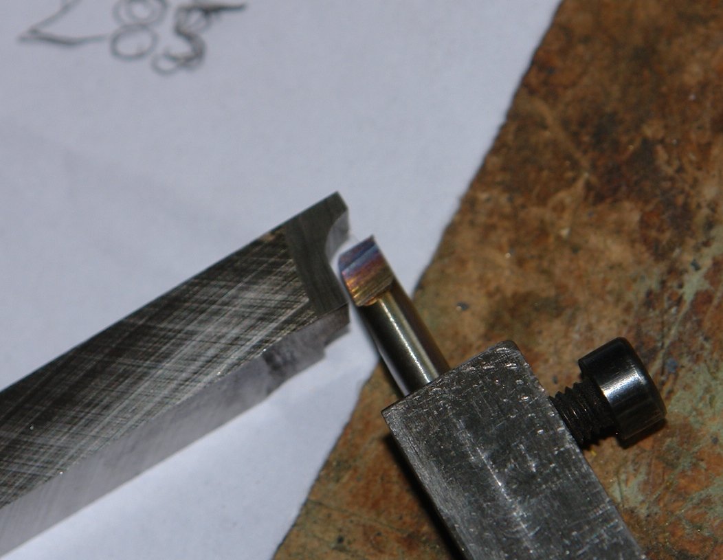
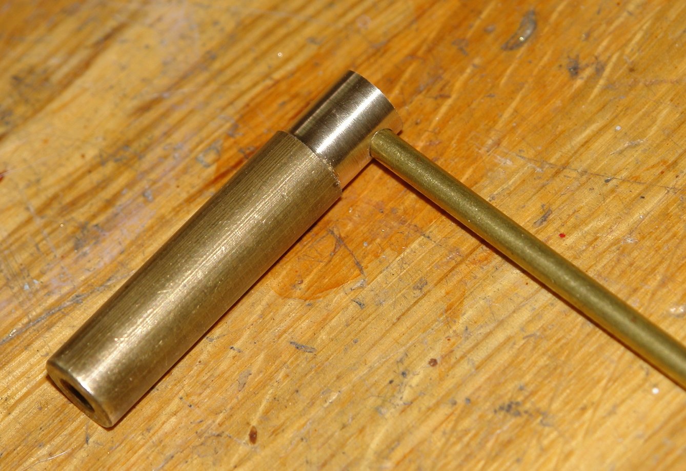
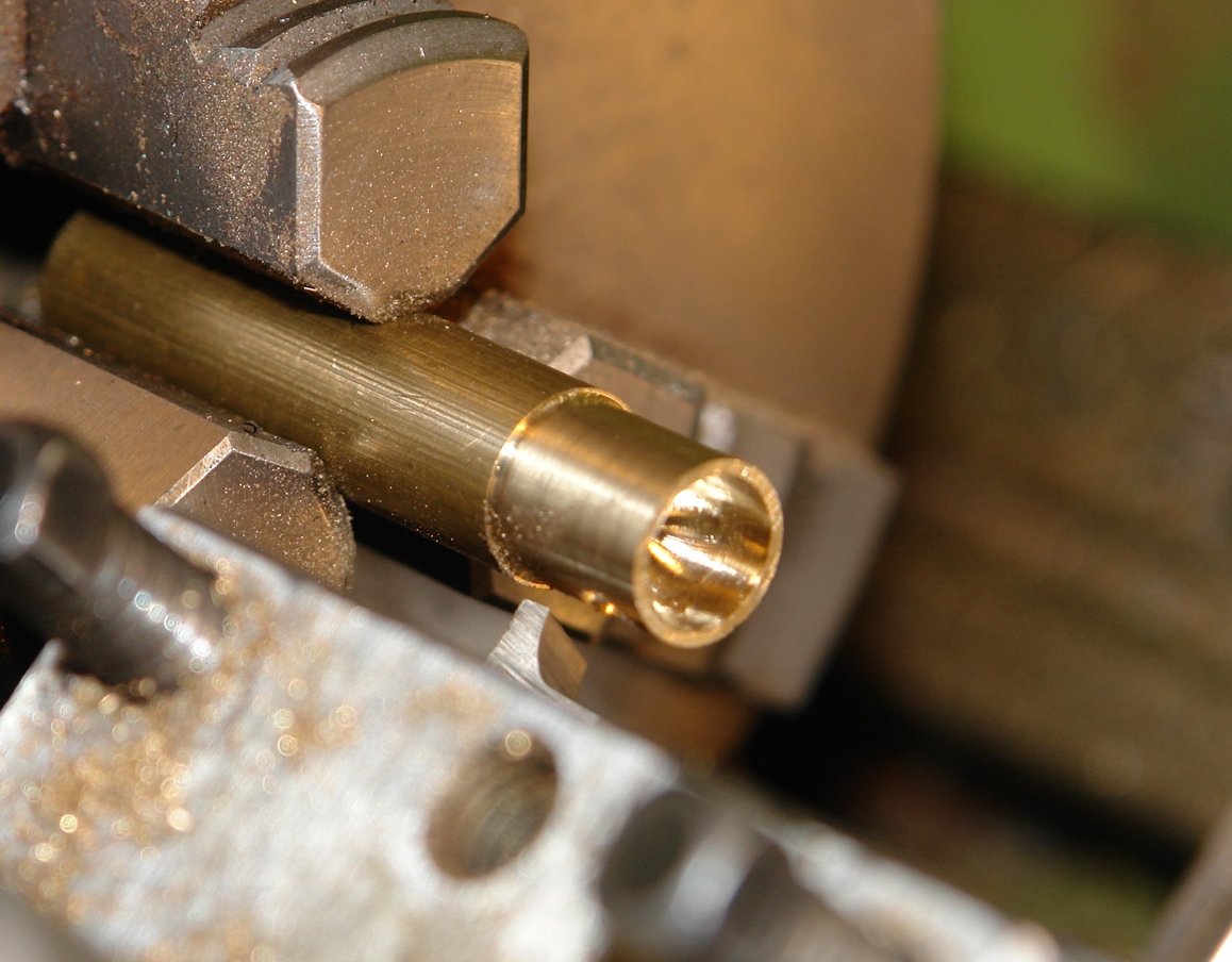
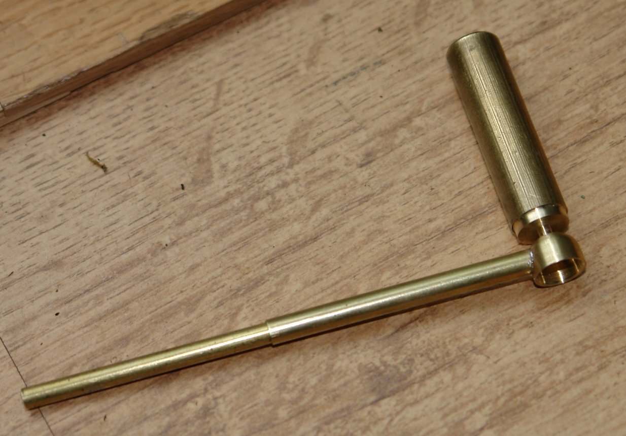
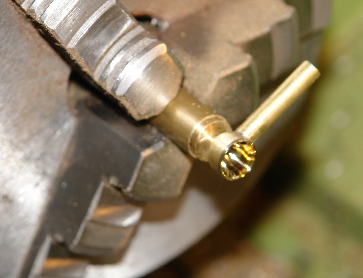
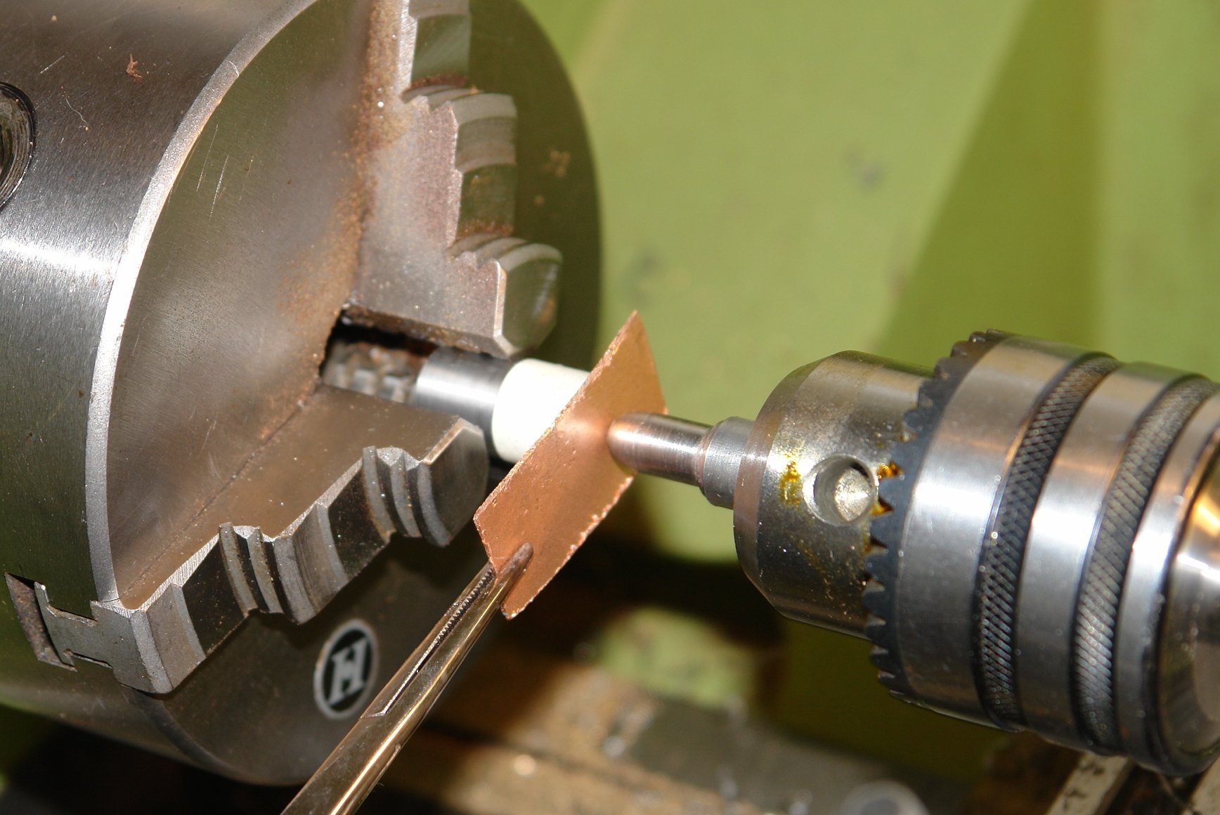
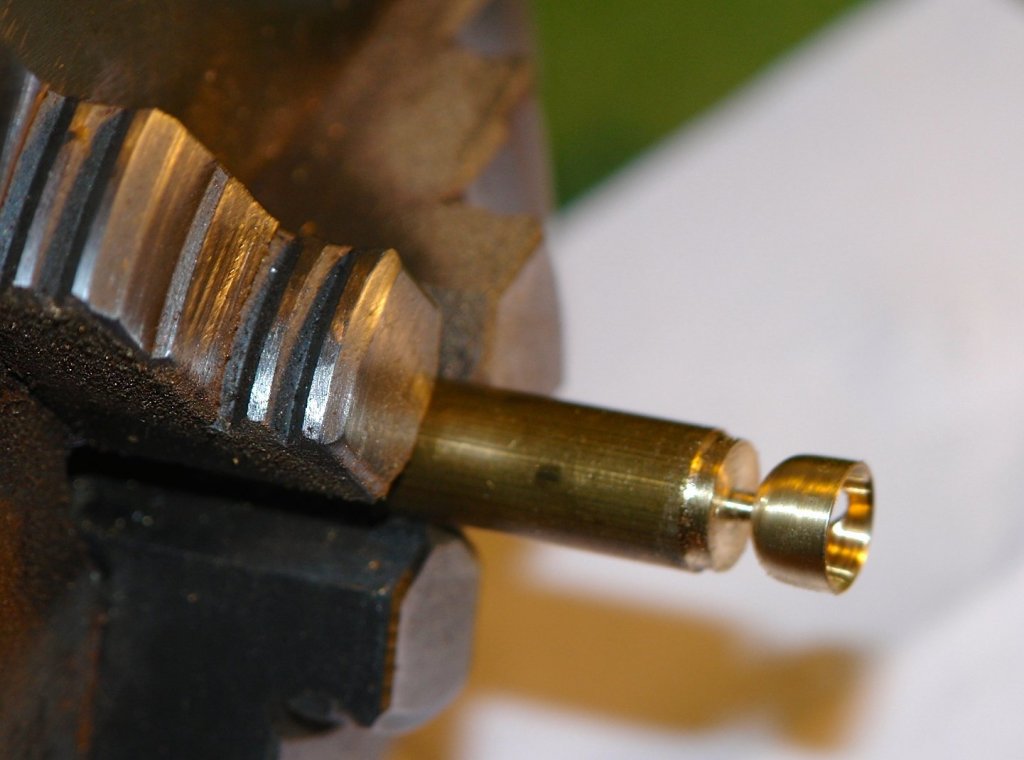
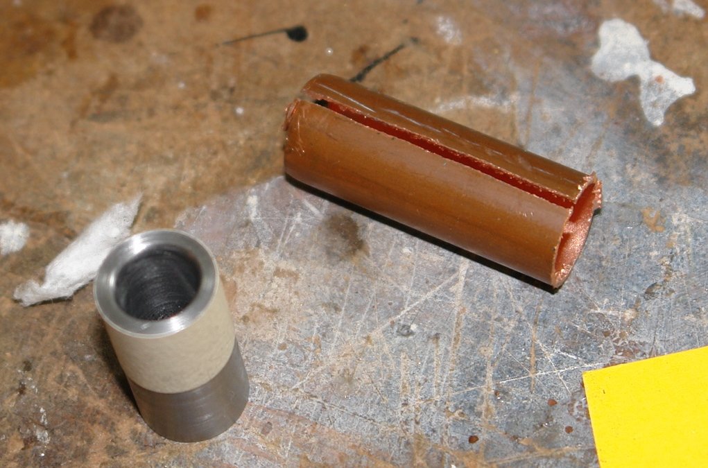
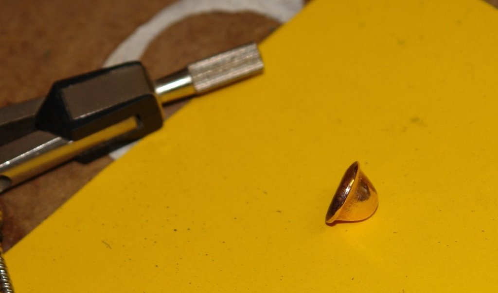
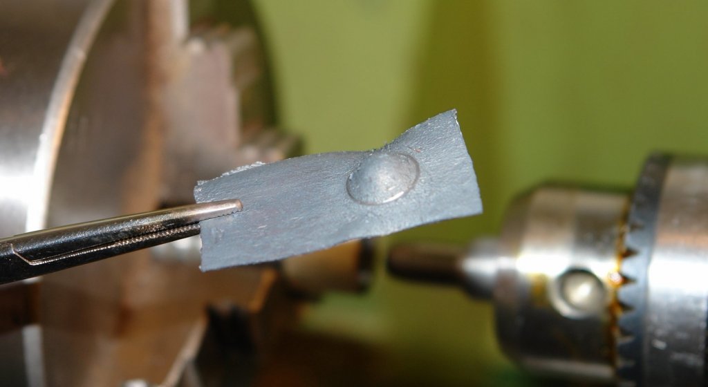
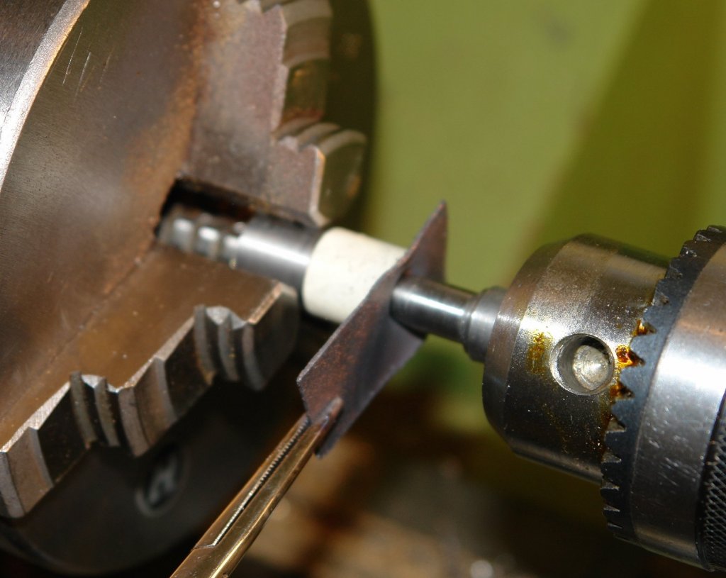
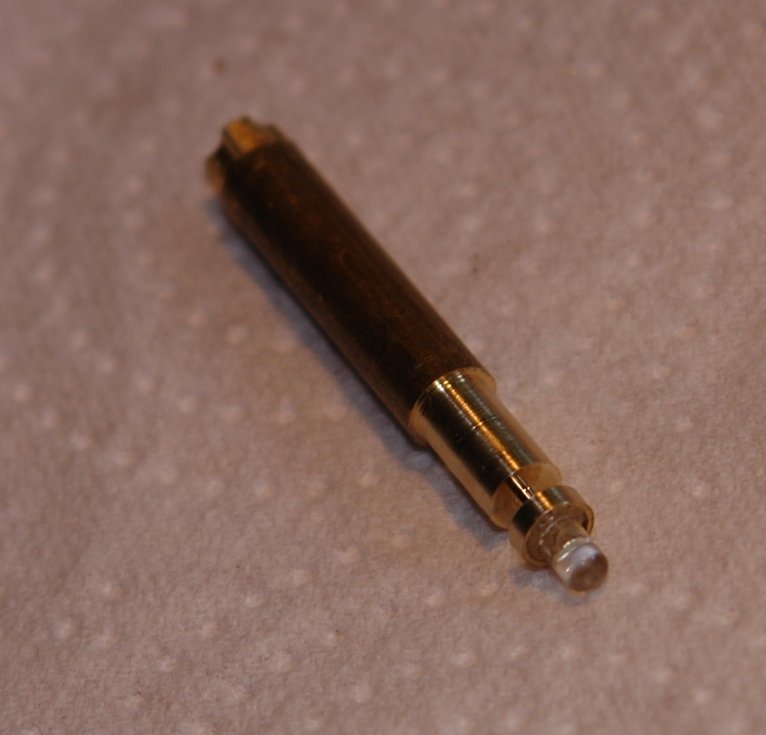
 And so to phase 2 of the vent cowl experiment - the machined option. The cowl "bell" is .400" outside diameter (OD) by .300" long. I turned down brass rod to the .400" OD and cross drilled a hole half way through the bar to take the tube which would form the inner shaft of the cowl. I then ground profile tools from HSS tool blanks. The external profile was drawn out on paper which was then glued to the tool blank to form the grinding guide. I decided to form the inner profile in two stages - firstly creating the internal spherical end by pre drilling to a depth of .250" with a 3/16 twist drill and the plunging a .320" diameter round ended milling cutter, again to a depth of .250". The inner profile tool was thus made simpler as it only required shaping to form the mouth of the cowl. I had to take care with the bore depth to avoid the external profile running into it. I took it carefully applying the check twice cut once rule. The external profile cut was taken slowly with the lathe turning at a moderate speed and using cutting fluid. I then used concentric tubes to form the shaft. The inner tube penetrating through the hole in the "bell" and the outer tube butting up to the external profile. I though this would give me the best chance of getting a good neat joint. The assembly was then soldered using a small ammount of solder paste and a propane torch. I then cropped the tube to length and remounted the assembly in the lathe to polish the inside of the cowl. Finally I cut the cowl from the bar with razor saw, filed the stub smooth and polished. Having tried the 2 options I am going ahead with the second option. It was quicker and gave a more accurate representation of the cowl shape.


- 882 replies
-
- 11
-

-
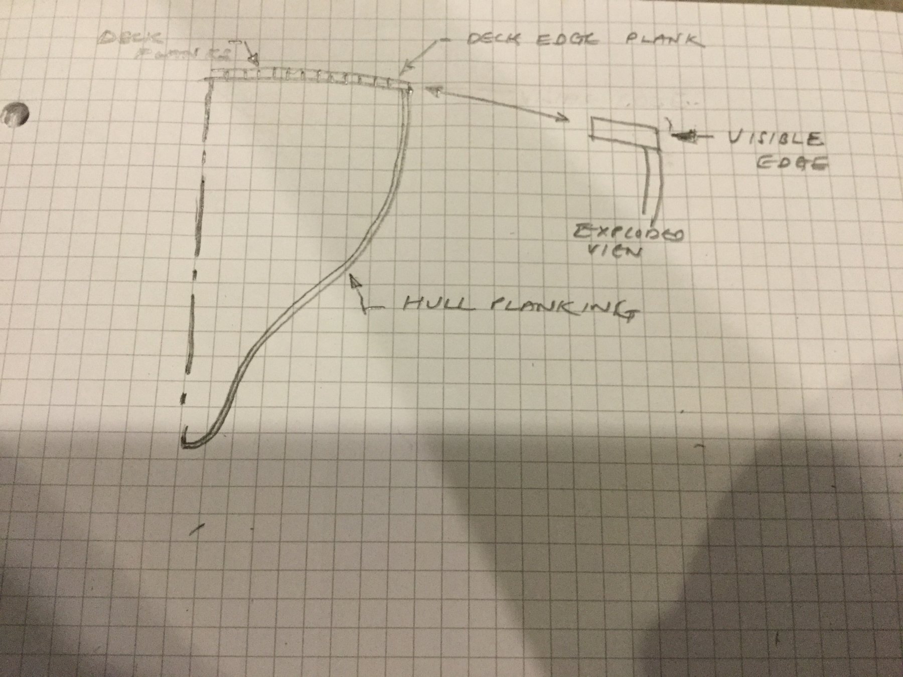
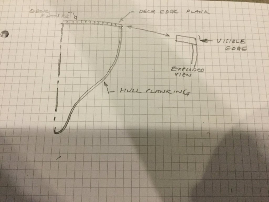
Julie, The sketch may help. When to lacquer depends on what is happening at the deck edge. If it's like the sketch it's better to get thr deck planking done before finishing the hull.
-
Julie Will you be able to see the deck edge plank when viewed from the side. If you can see it then it would be better for it to be in place before you lacquer the hull.
-
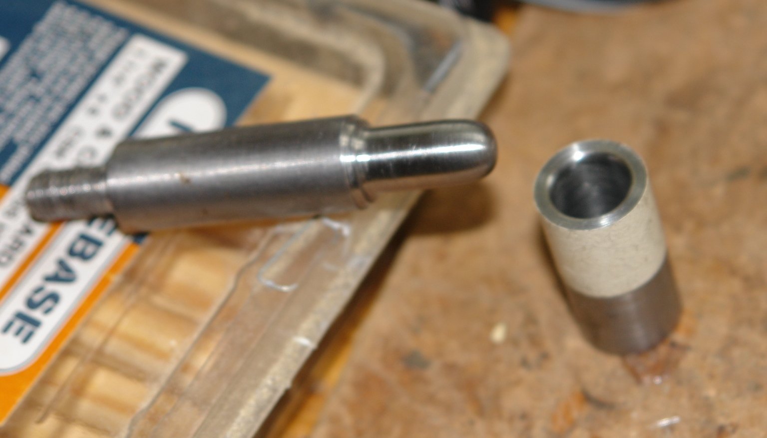
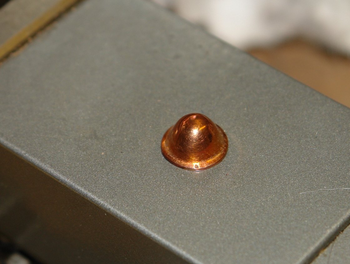
Thanks John - I also think the photos I have reflect two configurations - before and after refit. It all ads to the fun!!!!! Today I "finished off" the various deck fittings - at least that is until I discover more when I get to rigging. But for now that is it. For a distraction I though I would have a go at making the bell mouth of the vents - four needed in total. This is a first time of doing this and I have a couple of options to try. Today I had a go at the "pressed" option. I started by making the press tool consisting of a circular die with a corner radius and a plug with the bell form machined on to it. The die bore was .400" and the outside diameter of the plug was .350" - equal to the bore diameter less twice the thickness of the copper sheet I was using. The copper was a piece of domestic water pipe split and opened out. The press was the lathe tailstock. The procedure involved annealing the copper (heating to cherry red) and then pressing a dimple .020" at a time - in total I did 12 annealing /pressing steps. On the first one I had a bit of an experiment on how aggressive I could go with the pressing steps. The answer was "not very". So I did it again taking more care. To clean it up I glued it to the plug and filed and emery clothed it in the lathe. I was happy with the result. Next I will have a go at a machined option.


-
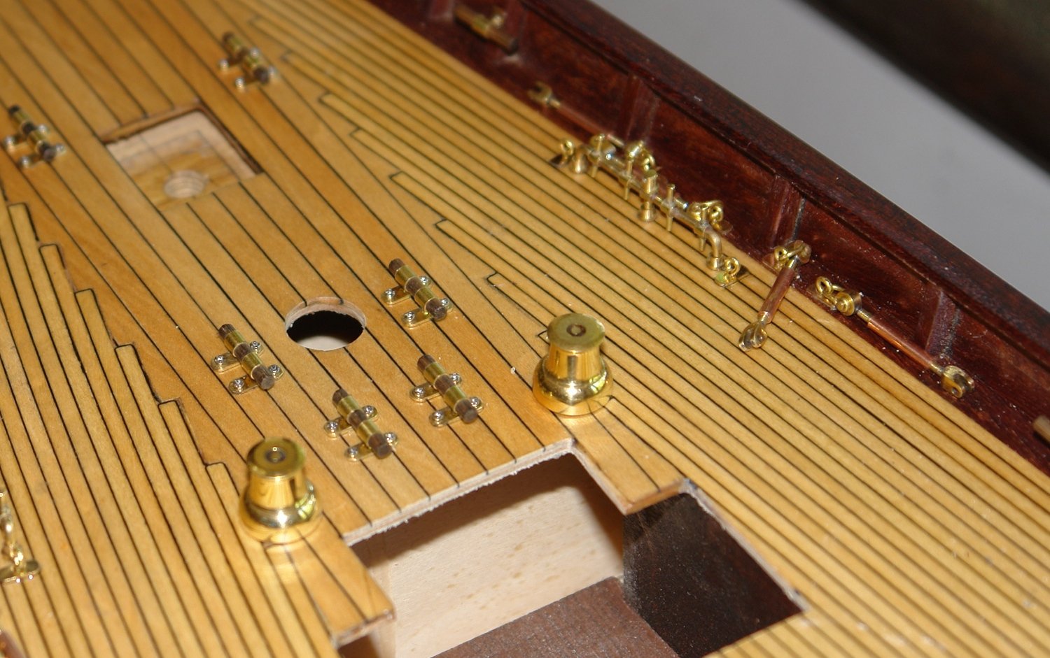
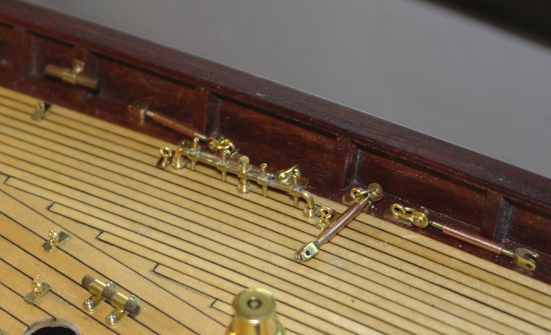
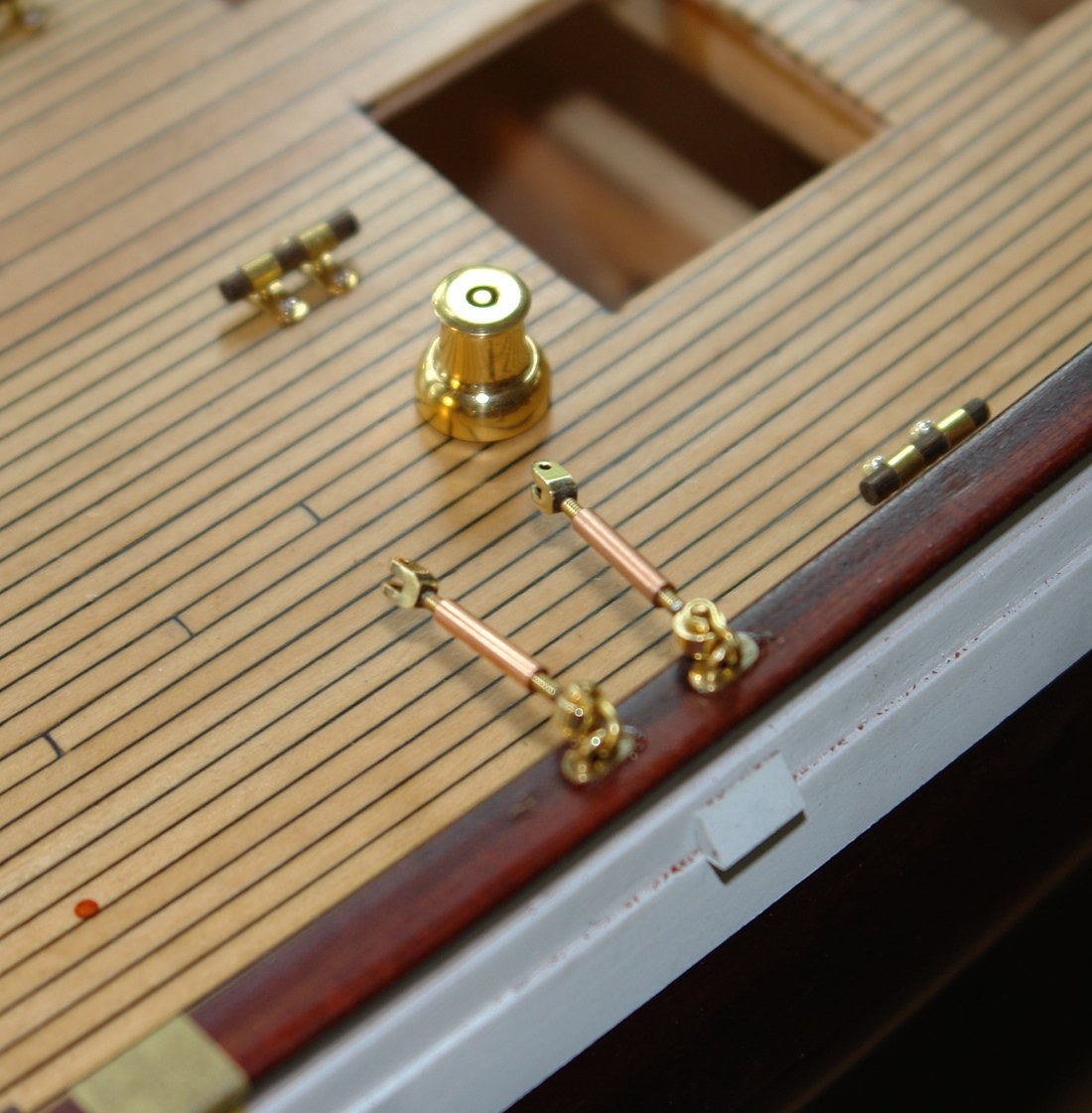
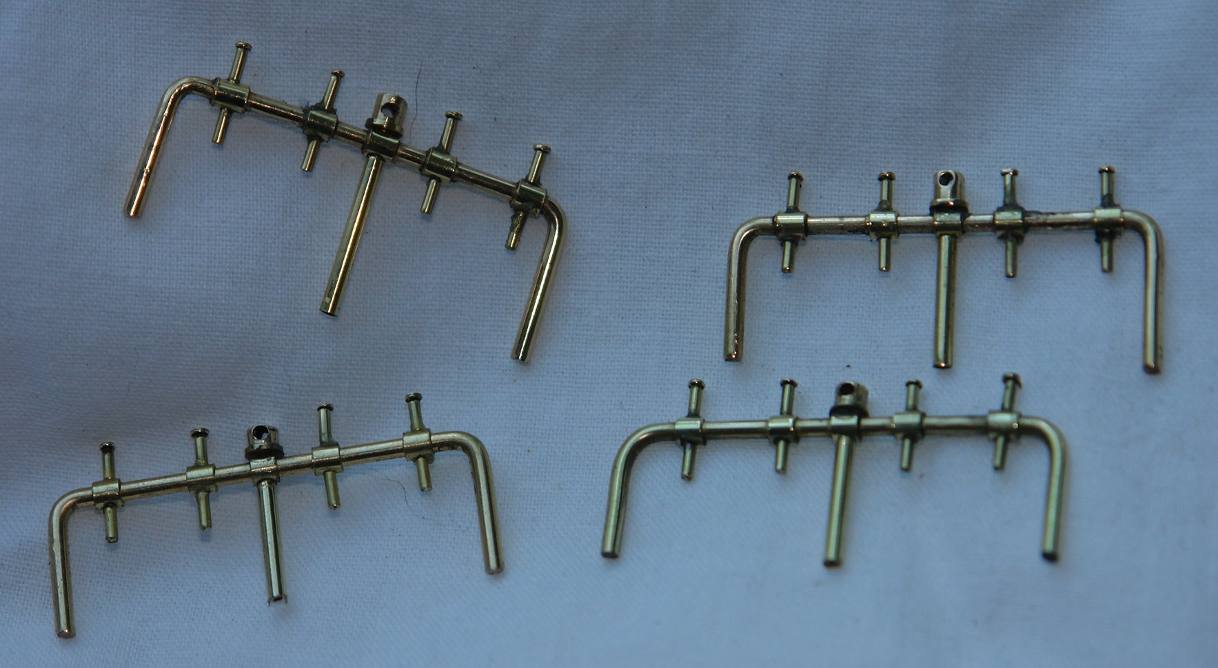
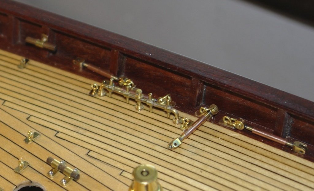
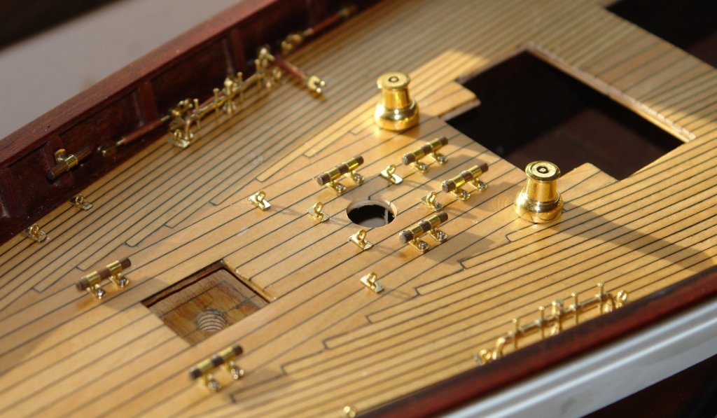
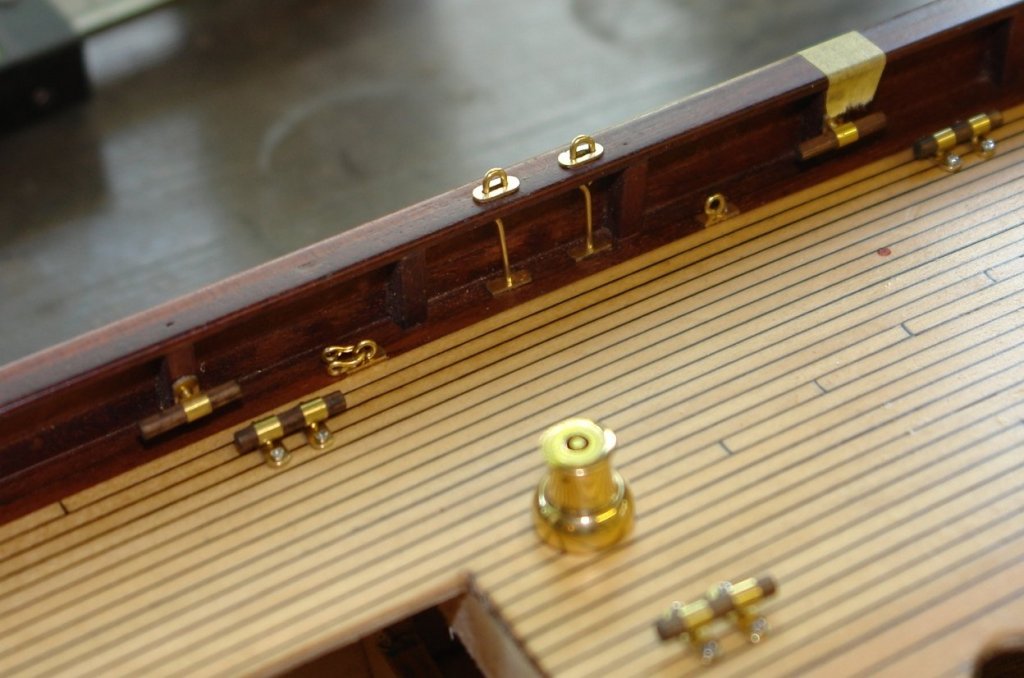
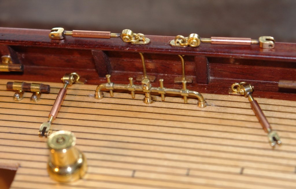
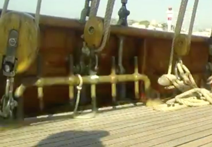
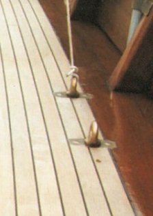
John, Richard - thank you very much. Mark, Thank you - it's really good to see you back in the groove. A bit more progress - all 4 sets of pin rails and turnbuckles installed. The picture shows starboard foremast fixings. Then time to get on with the multitude of deck eyes. Before and after photos below. Getting the location right is somewhat of a challenge. I don't have a lot of confidence in the plans so I spend a lot of time scrutinising photographs. Interpreting the relative positions of one item to another and constructing the chain of evidence back to a known and accurately located point takes an age and slows progress to a snails pace. Not all deck fixings are the same - some of the deck eyes sit on pedestals.

-
Julie Doubling the thickness of the veneer was probably a good call. I did the same on Altair. I didn't get any "clinker" on 2nd planking Endeavour, probably one of the few benefits of the very thin mahogany strips supplied with the kit. I think I was lucky in avoiding any sand through although I did take a lot of care. Finishing the hull is fairly quick compared to planking and hence provides the boost of a much higher reward for effort ratio. You are nearly through the worst of it!!!!
-
Julie. The tricky bit now is not to sand through the veneer. Better to use fine grit emery paper and take it very slowly with light pressure.
-
Nice work Dan. Impressive how you achieved such uniformity on the cut outs given the small scale at which you are working.
- 287 replies
-
- 3
-
-
- michelangelo
- ocean liner
- (and 1 more)
-
Frank, How did you make the "T" pieces where the rail joins the stancheon?
- 18 replies
-
- 1
-
-
- honey bear
- fishing
- (and 1 more)
-
HMS SUSSEX 1693 by 8sillones
KeithAug replied to 8sillones's topic in - Build logs for subjects built 1501 - 1750
Amazing! -
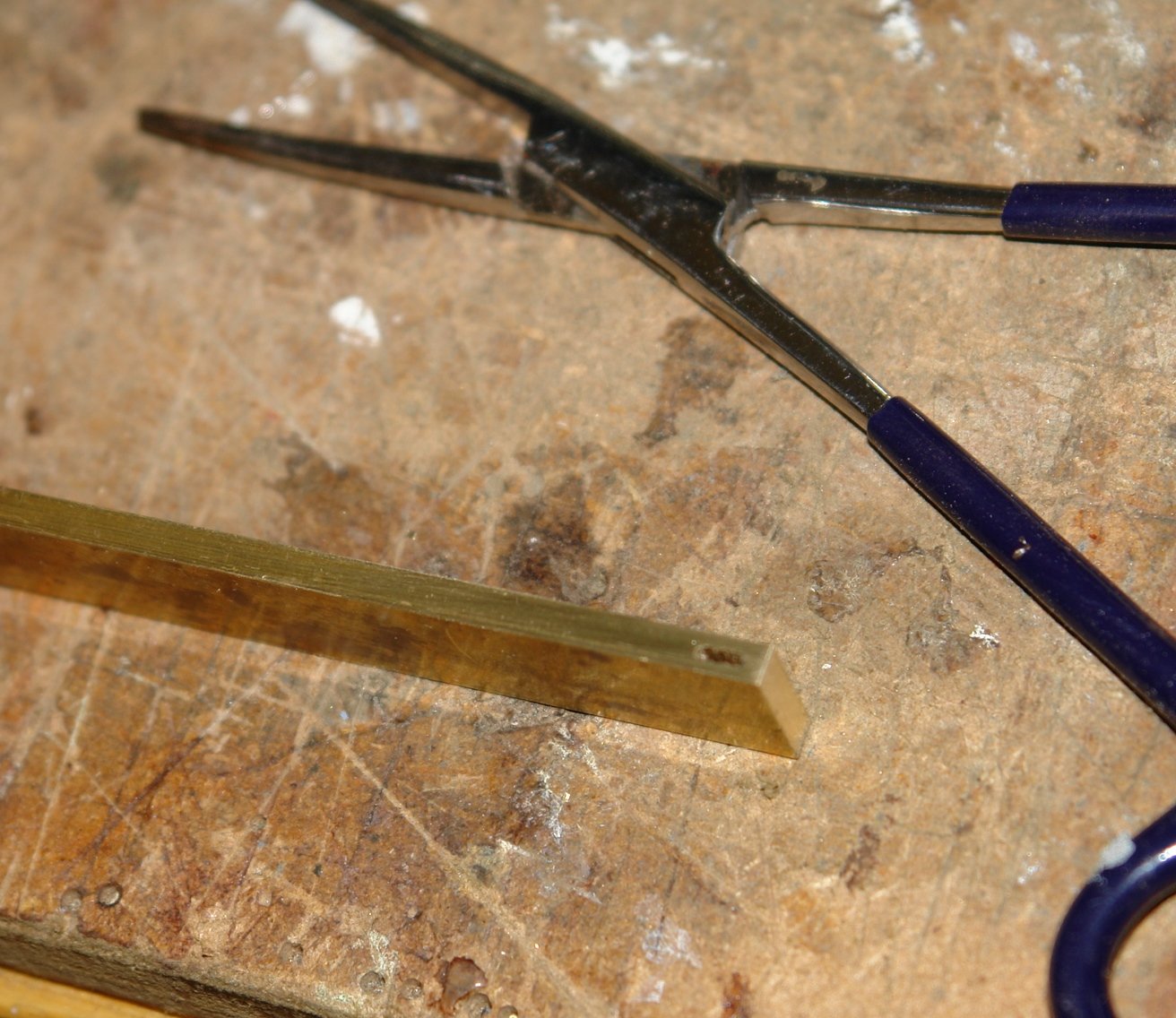
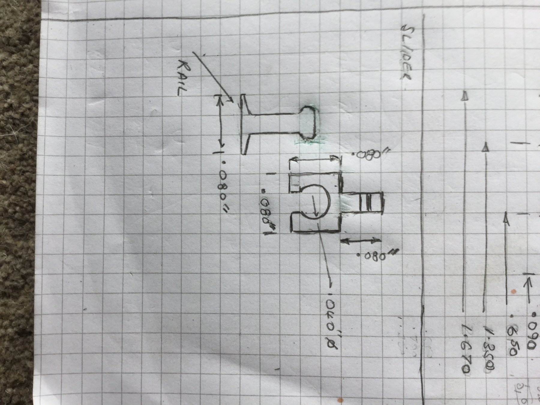
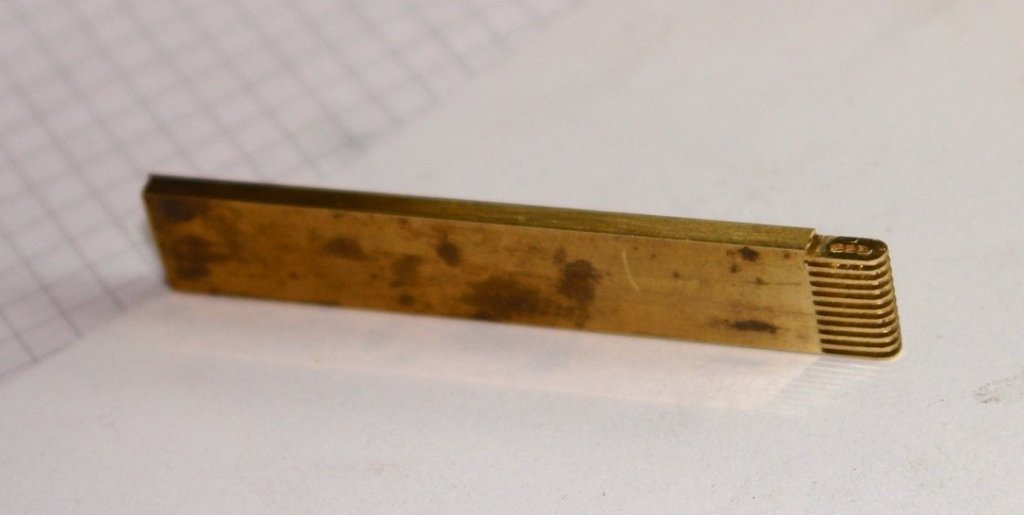
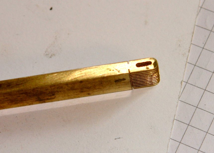
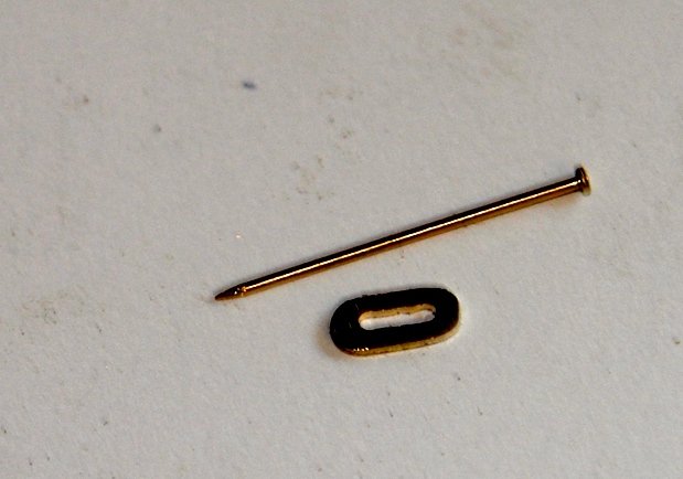
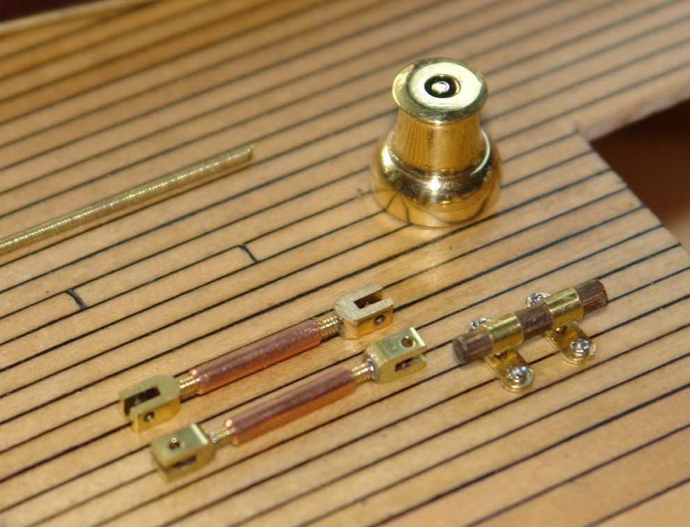
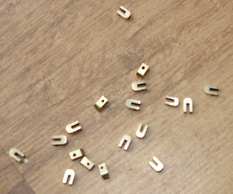
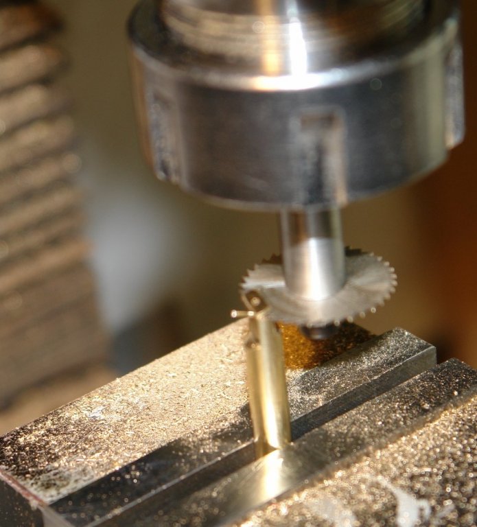
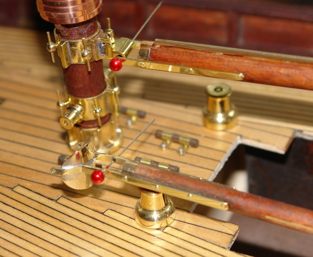
Thank you Per and all of you who have visited. Today I spent some time working on the port side main mast stay fixings. I started with a number of small plates which fit around the rail fixing for the turnbuckles. They are .125" x .260" x .025" and have a central slot of .040 width. I needed a way of making a number of reasonably identical plates. I did this as follows:- I drilled the slot end holes and then cut out the middle with a piercing saw. I profiled one end and cleaned up the slot with a 1mm end mill. I only used the end mill in the plunge mode as any sideways pressure causes breakage. I then cut the plates to width using a .025" slitting saw. I profiled the other end as far as I could using piercing saw and then needle file. Having done most of the shaping I separated the plates from the bar and cleaned up the profile with a file. The plates fit on the rail as follows:- The turnbuckles were then mounted. The two remaining turnbuckles are deck mounted. These were located together with the belaying pin rail.One down three to go!


-
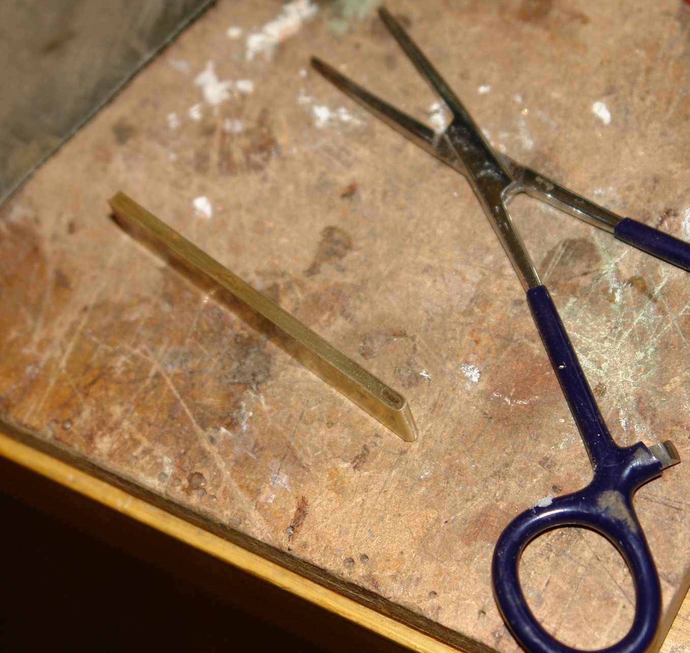
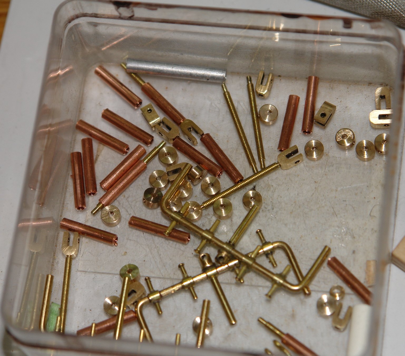
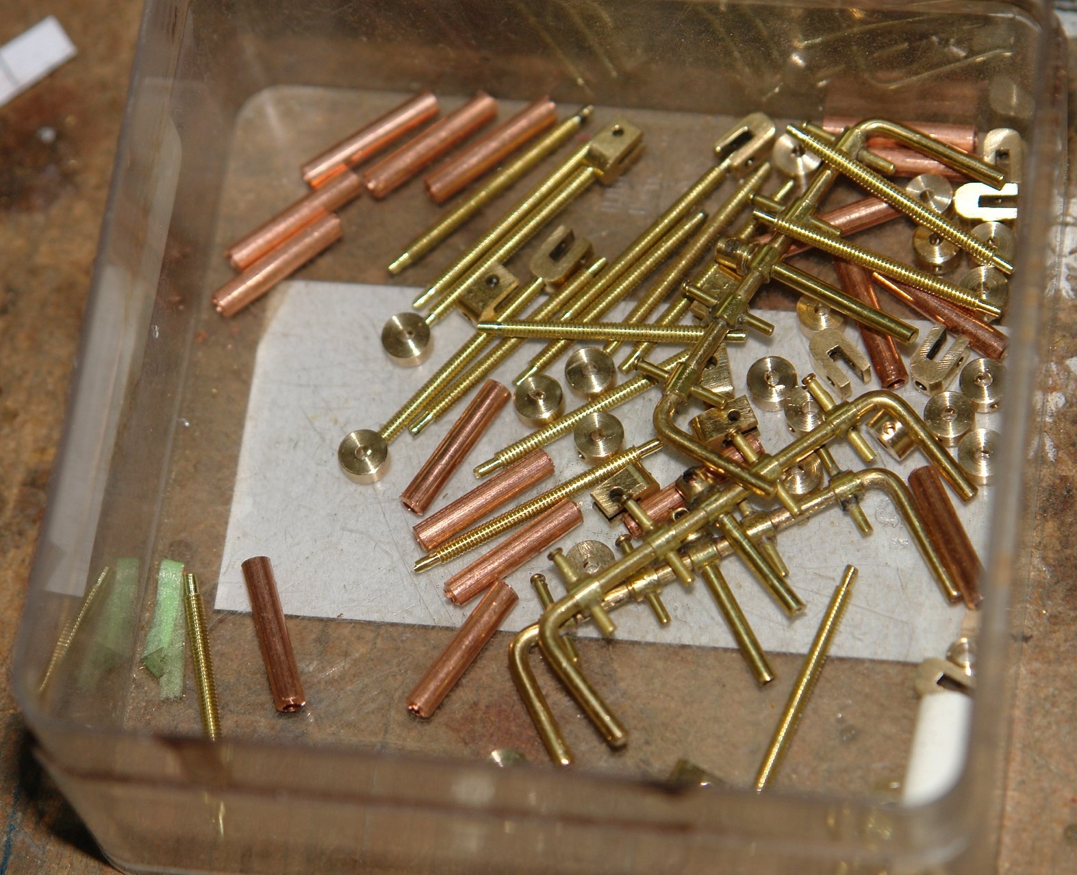
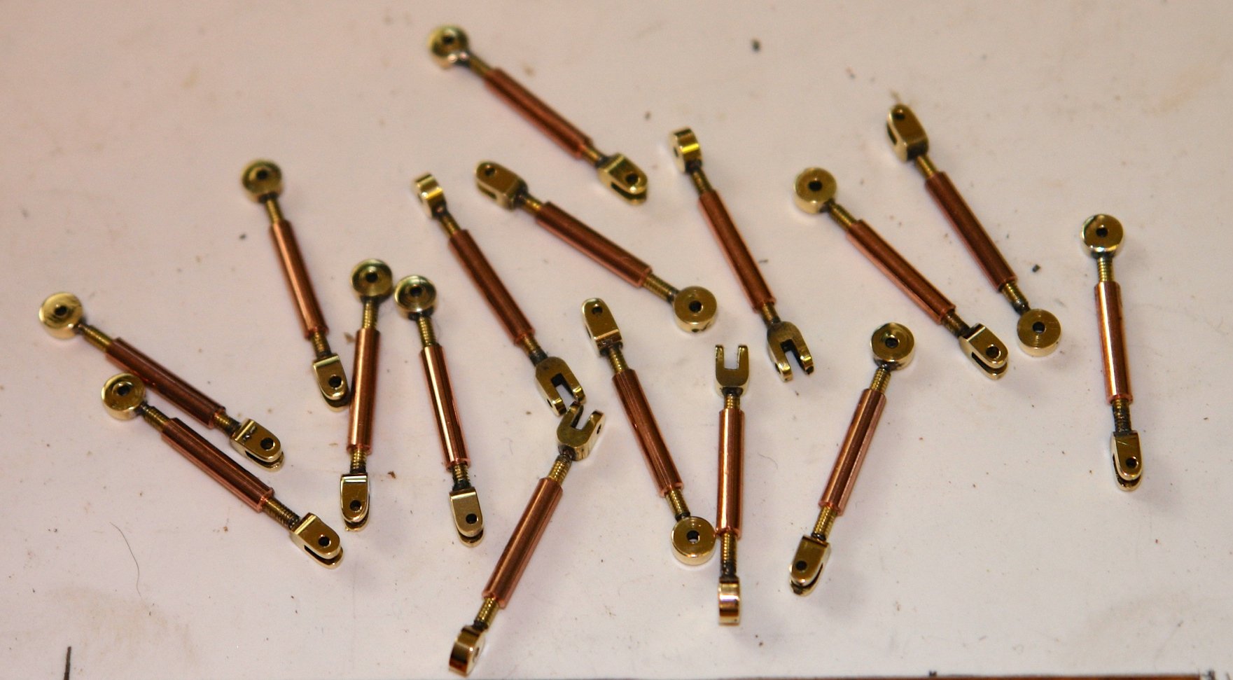
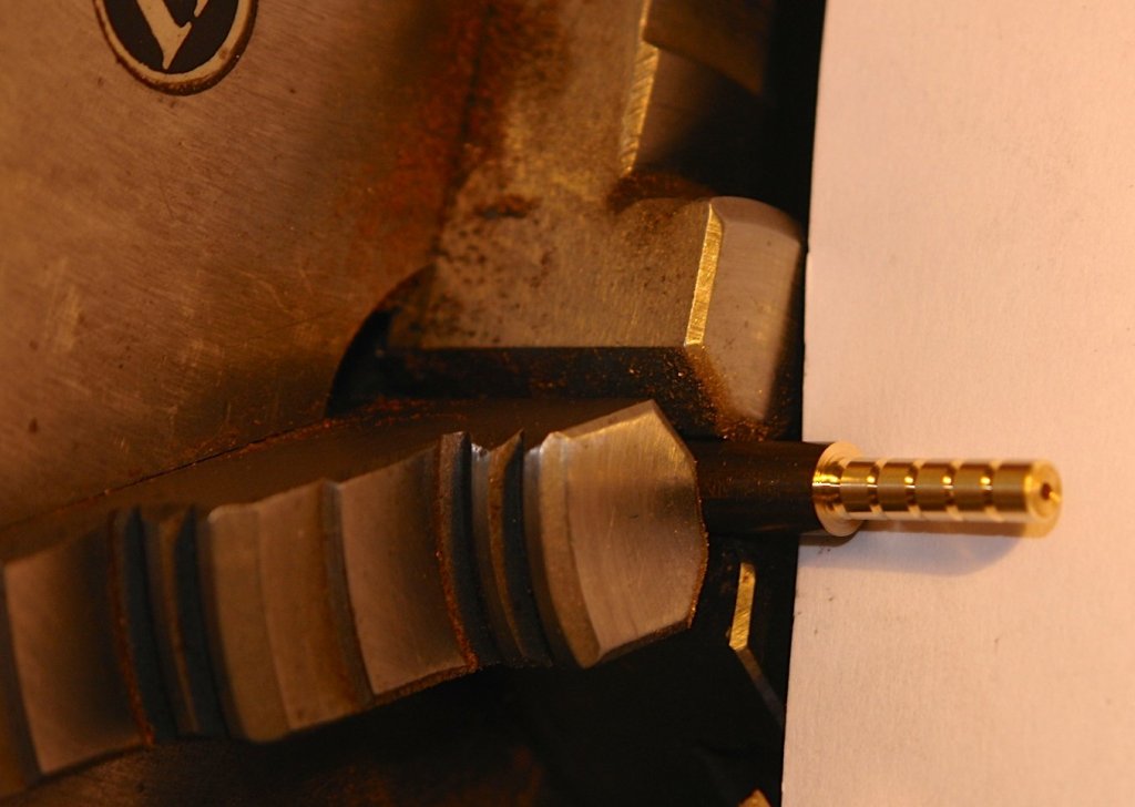
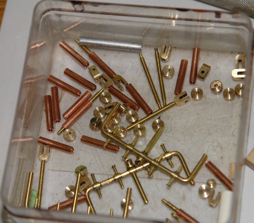
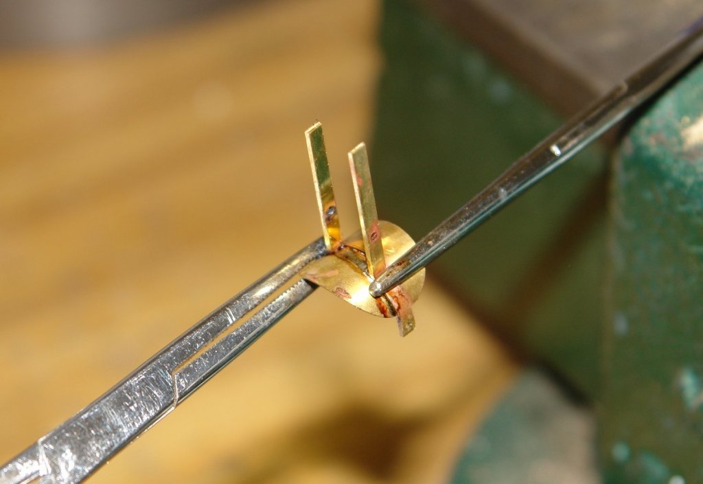
Thank you John, I have had a production run on turnbuckles. The shrouds require 8 per mast and 16 in total. I made these but a number of others are still required for various locations. The turnbuckles have a fork on one end and a boss on the other. I covered the fork in an earlier post and the boss was a straightforward tuning / drilling job. I had to tap more rod - in all I accumulated a pot full of parts. The boss's and forks were soldered in place using solder paste and a butane torch. The boss ends are attached to the deck via a deck eye and shackle. Both the shackle and eye are are from 1/32" brass wire.


-
Frank You shouldn't have any concerns about your models. Most of us do it for our own pleasure and the key criteria is to make something that pleases oneself. It is seldom the case that model makers achieve absolute accuracy and lack of information often constrains many of us to make something that looks about right. The degree of accuracy also comes down to personal choice. So my advice is to do it your way, you will be surprised how others at MSW appreciate whatever you choose to build. Thank you for looking at my builds, it's always good to get positive feedback.
-
Hello from the Colonies ... Ontario, Canada
KeithAug replied to albergman's topic in New member Introductions
Hello Frank. it looks like a fine model. I'm sure you will find most members have a broad interest in anything that floats or sinks. You should post your pictures. -
Hi Nils They remind me of many pleasant visits to the beer tents at Munich's Oktoberfest.
- 2,625 replies
-
- 5
-
-
- kaiser wilhelm der grosse
- passenger steamer
- (and 1 more)
-
Nils Like a fine wine - you get better and better with age.
- 2,625 replies
-
- 6
-
-
- kaiser wilhelm der grosse
- passenger steamer
- (and 1 more)
-
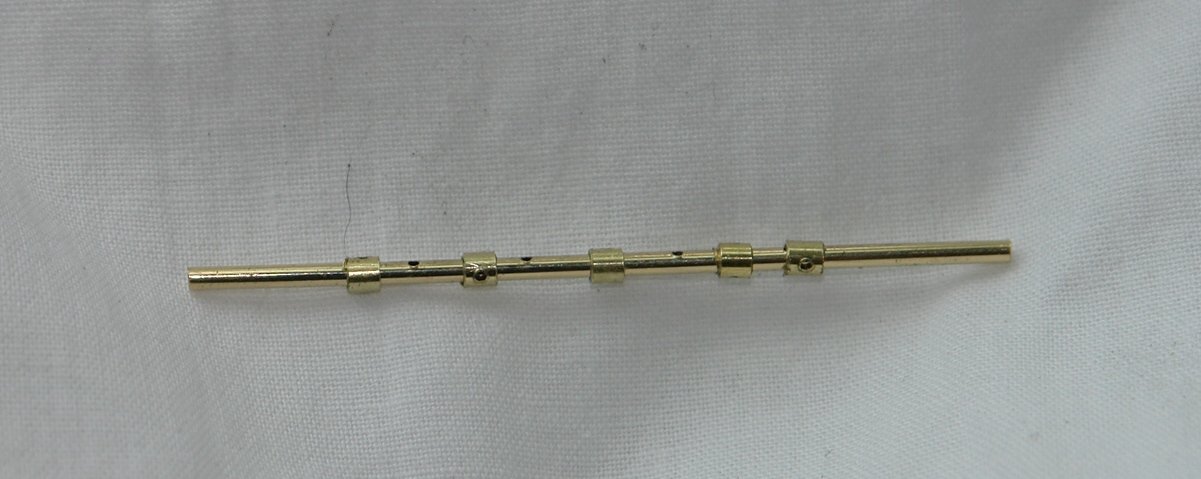
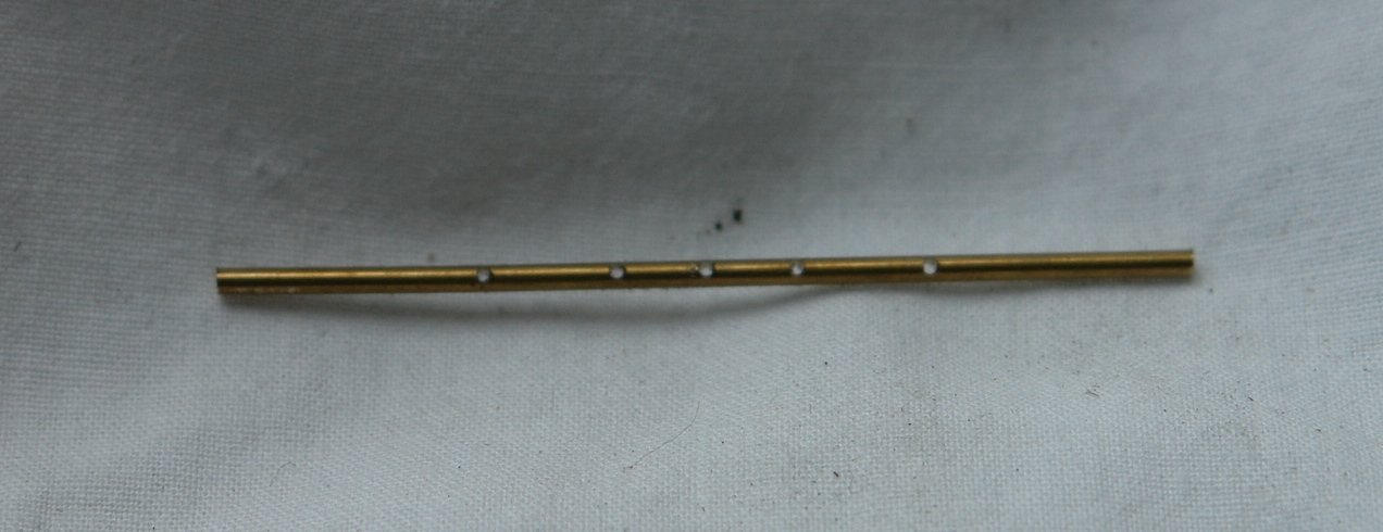
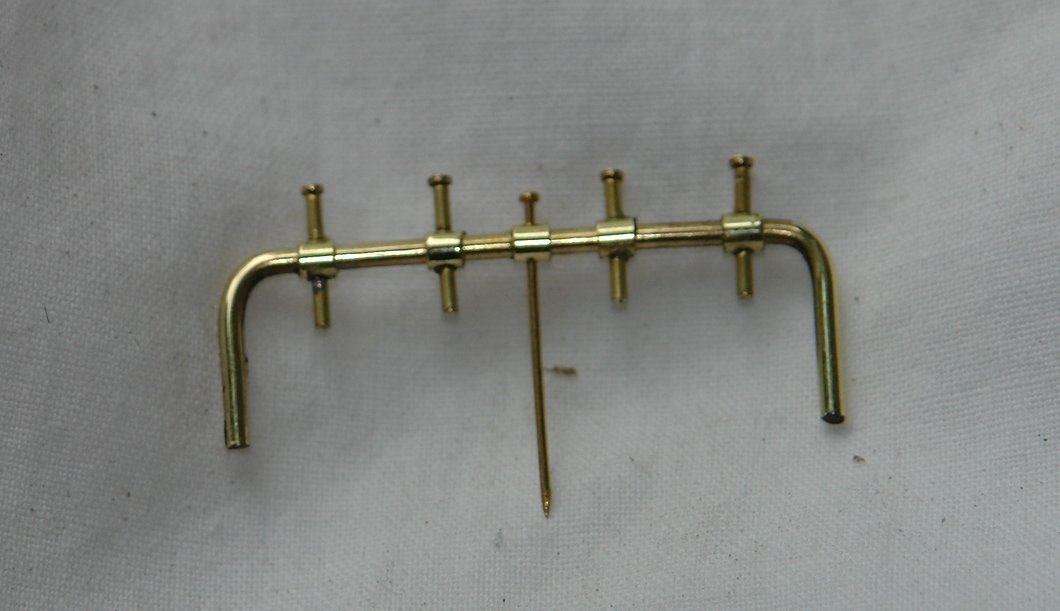
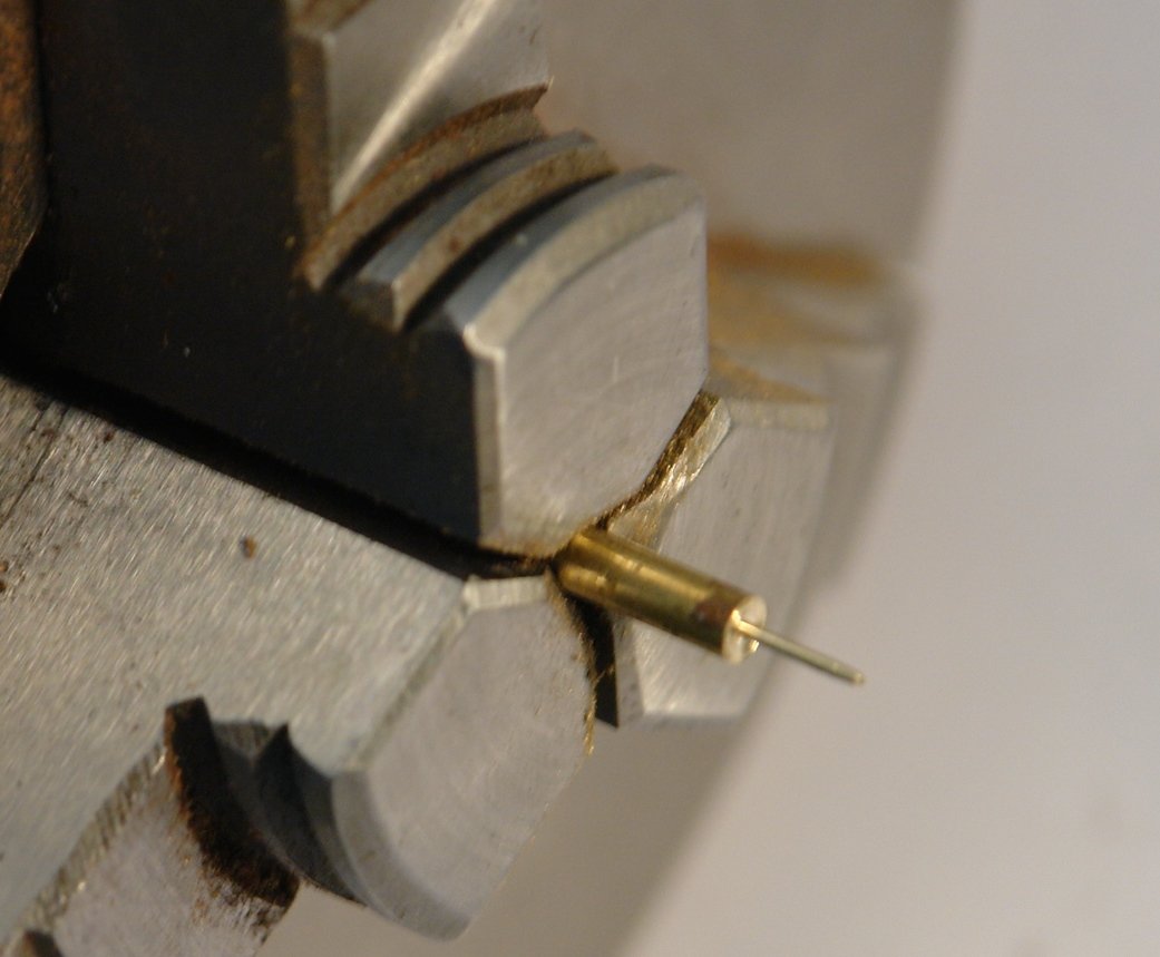
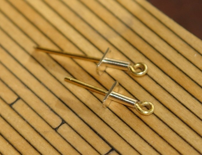
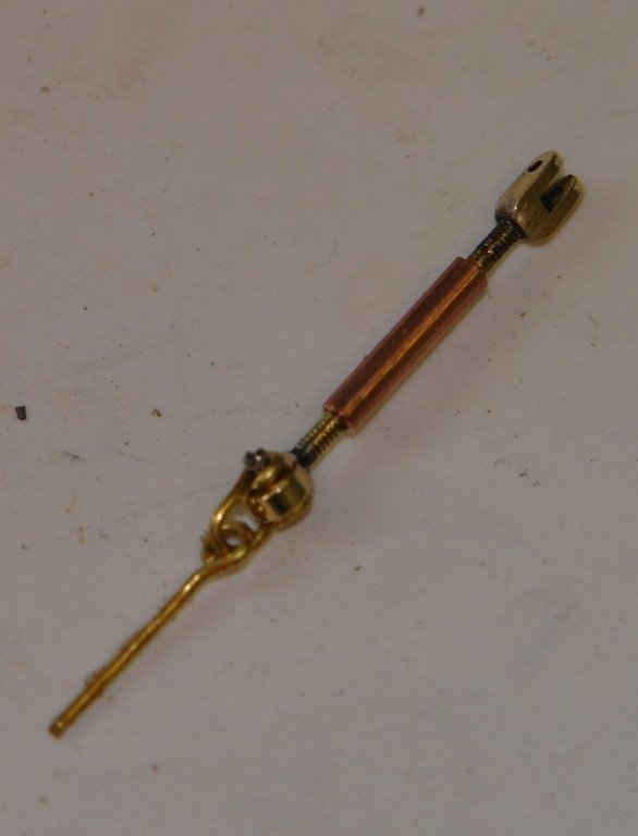
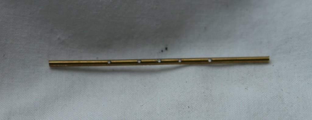
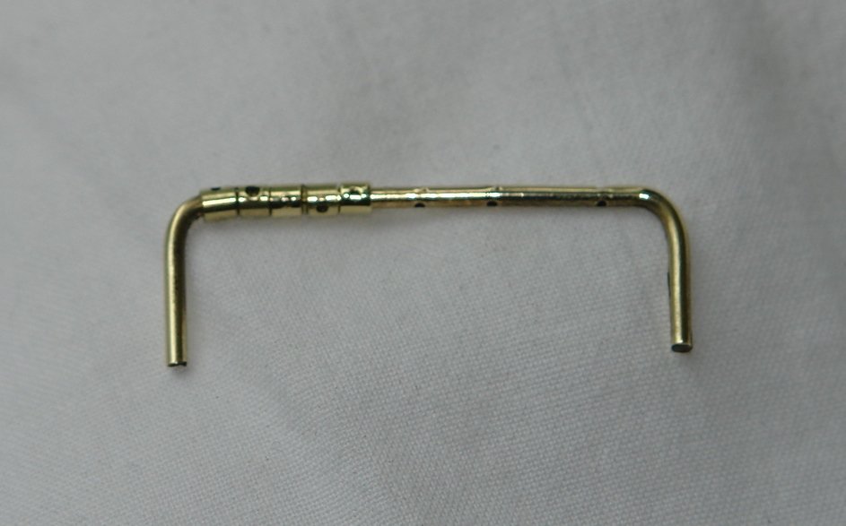
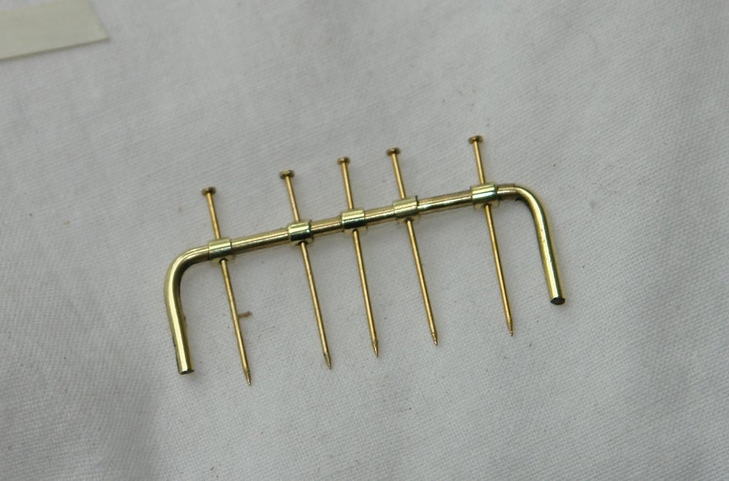
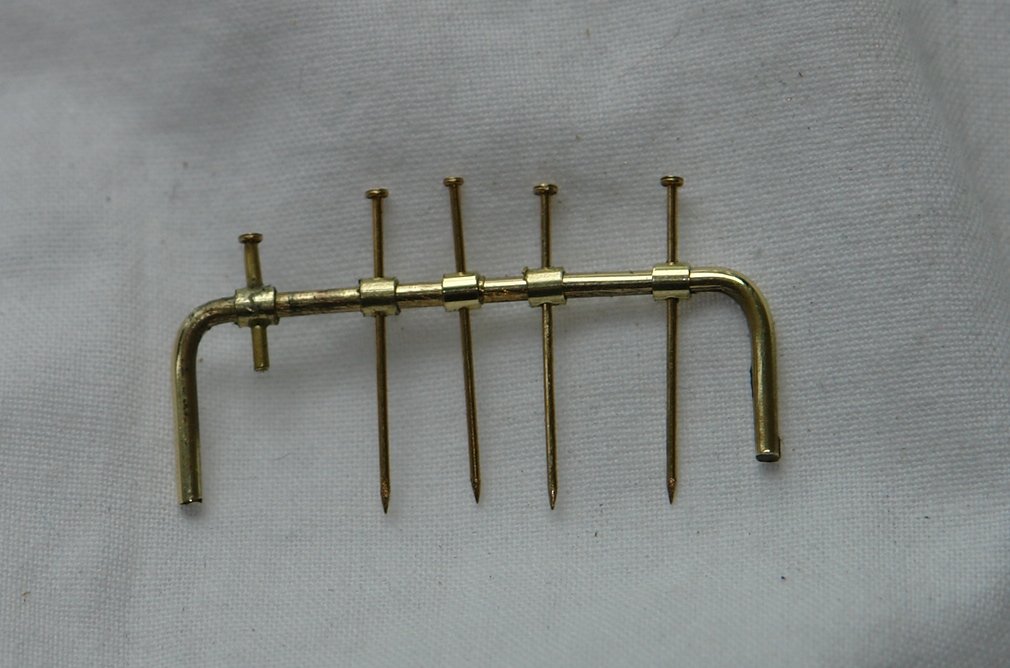
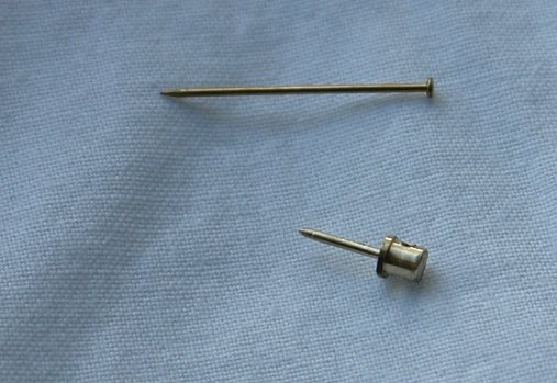
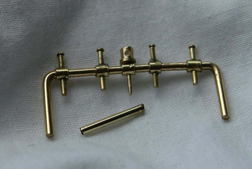
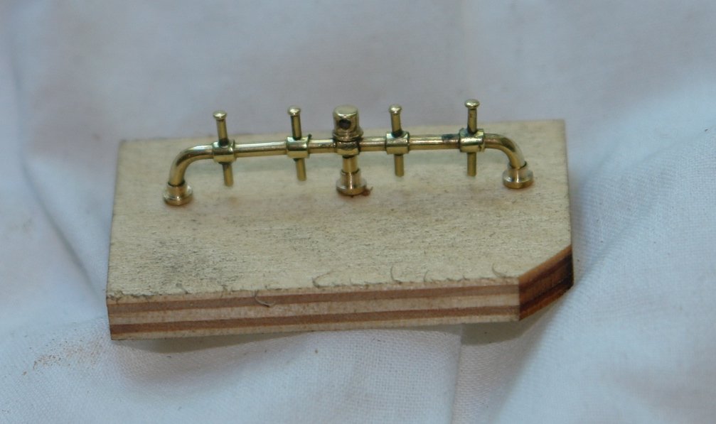
Richard / Michael - Thank you. I made up a couple of turnbuckles - but have still to round off the square ends. They are about .750" long. I then moved on to making the belaying pin rails which sit inboard of the bulwark on either side of the main and fore masts (4 in total) The rail was made from 1/16" brass wire - 2.2 inches long and cross drilled with 5 holes of 1/32" diameter. At this size I find even my finest centre drills are not pointed enough so I "drill" the starter holes with a broken .040" end mill ground to a fine point. The thickening where the belaying pins penetrate was created by slipping on pre cut and drilled sleeves. The wire was then bent to shape with pliers and a small hammer. The first 3 went well but then I switched to another wire for the 4th which was much more brittle and broke twice. I softened the 3rd attempt with a butane burner and all was well. The sleeves were aligned with sewing pins which formed the core of the belaying pins. (pins .025" x 0.7") Micro-bore tube was used to create the belaying pins. The centre position is a support come bracket. Making this involved some "fine" turning. The bracket was made from .125" rod with the mounting spigot turned down to .030" to go through the hole in the wire / sleeve. My lathe isn't very small but by making very small tools and taking small cuts I manage to make 4 good ones out of 5 attempts. The mounting leg was made from tube and inserted over the spigot. I then did a bit of polishing and made the mounting brackets for the 3 legs. I then stopped to admire the sunset from the garden. Quite dramatic - taken without any filters.


-
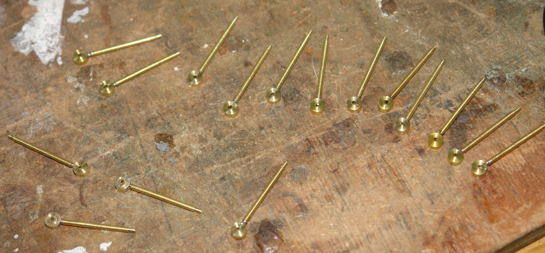
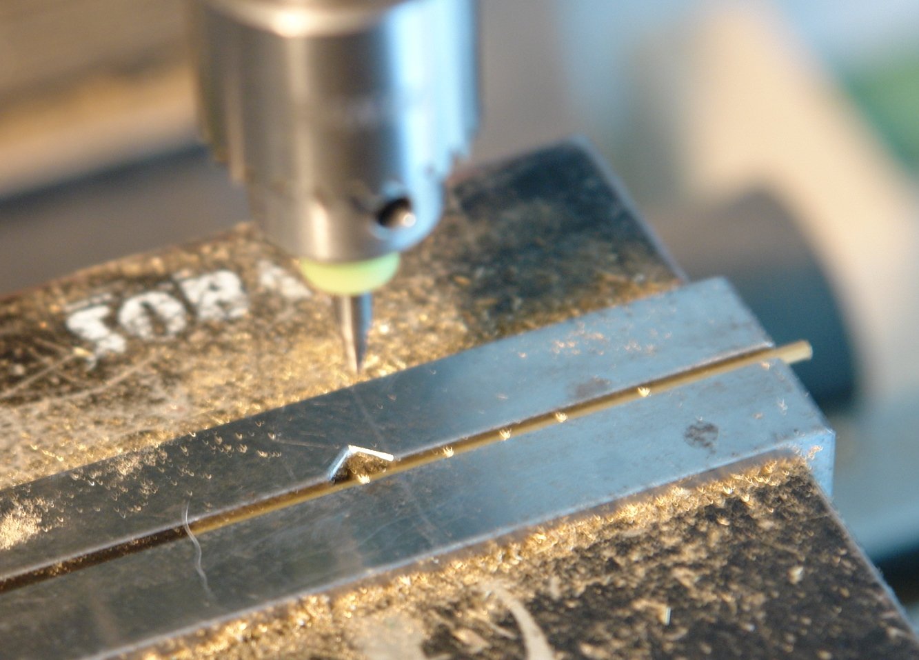
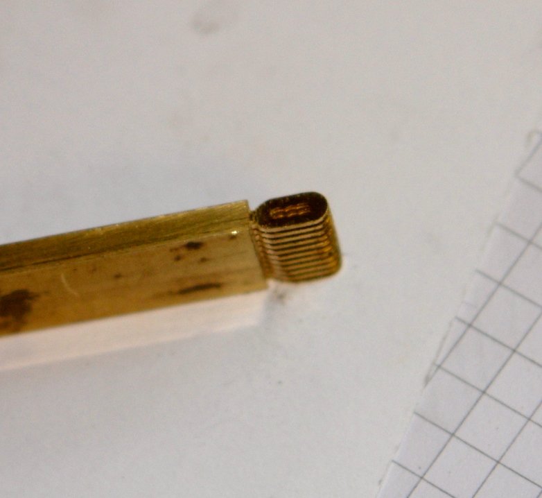
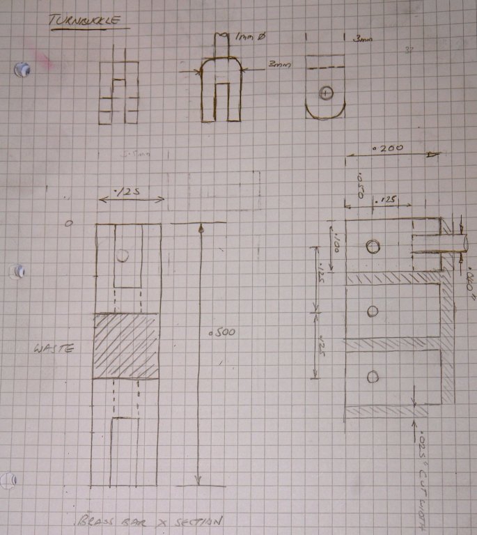
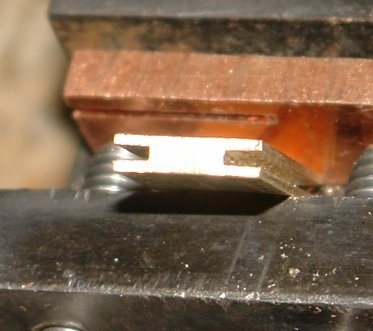
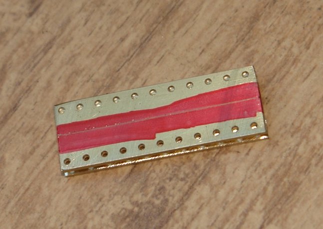
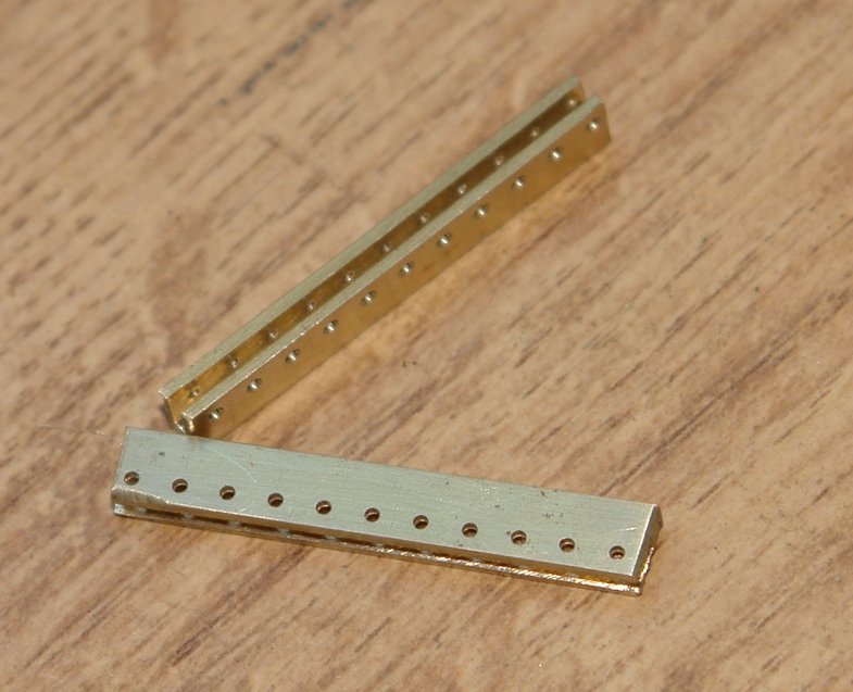
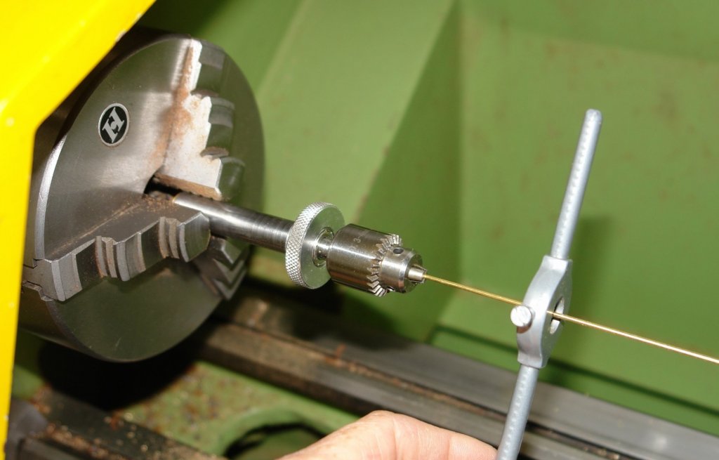
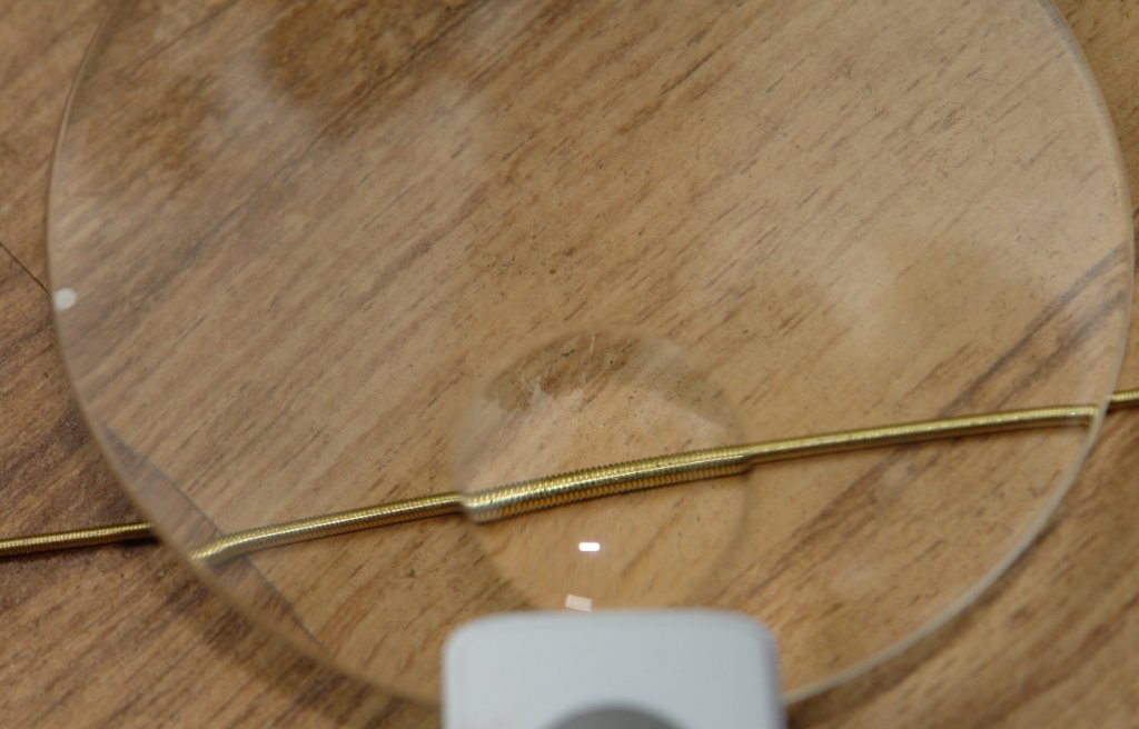
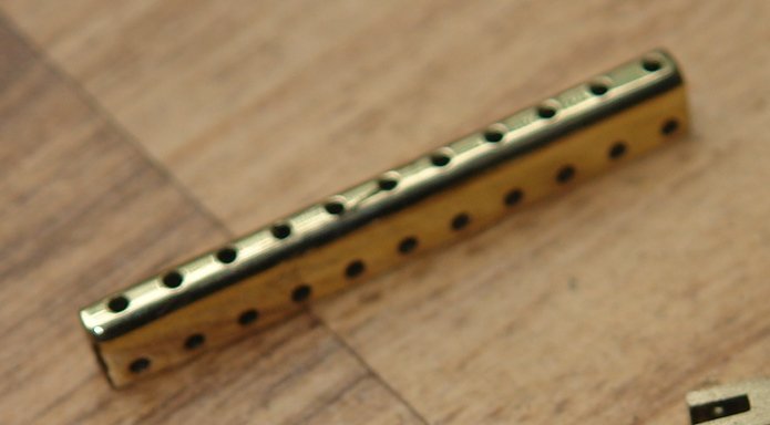
I thought I would carry on with the production runs by starting to make the turnbuckles - the body components are fairly straightforward so I thought I would start with the end brackets. I wanted to make them uniform so parting them off from a pre-shaped billet seemed to be the way to go. I needed therefore to do a bit of planning to get the machining sequences right. I started with a roughed out design. I had some .125" by .500" brass bar which I decided would form the basis of the end brackets, a row of brackets being cut from each edge. The finished brackets being .1" x .125" x .200" maximum dimensions. The through holes for the retaining pins (.040" dia) were all pre machined into the bar before slots were cut along the thin sides using a .030wide slitting saw. Holding the bar for the slitting operation involved a bit of head scratching but in the end I improvised a clamp using an upside-down lathe tool post with the workpiece held in the tool clamp. The slices out of the corner of the tool post were made by a previous owner - honestly! It worked reasonably well - nice clean and uniform cut. The bar was then hacksawed down the middle and end milled to the finished height. I then hand filed the rounded end shape and polished the strip on the buffing wheel. Finally the individual brackets were parted off from the strip. I then made the treaded rod using .050" wire. I quickly became board with hand screw cutting - mannnnnnny rotations per inch. So I improvised and stuck the rod in the lathe and finish it in a few seconds. I don't really know why I bothered as the threads were virtually impossible to see with the naked eye.


-
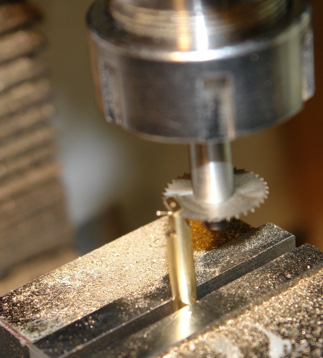
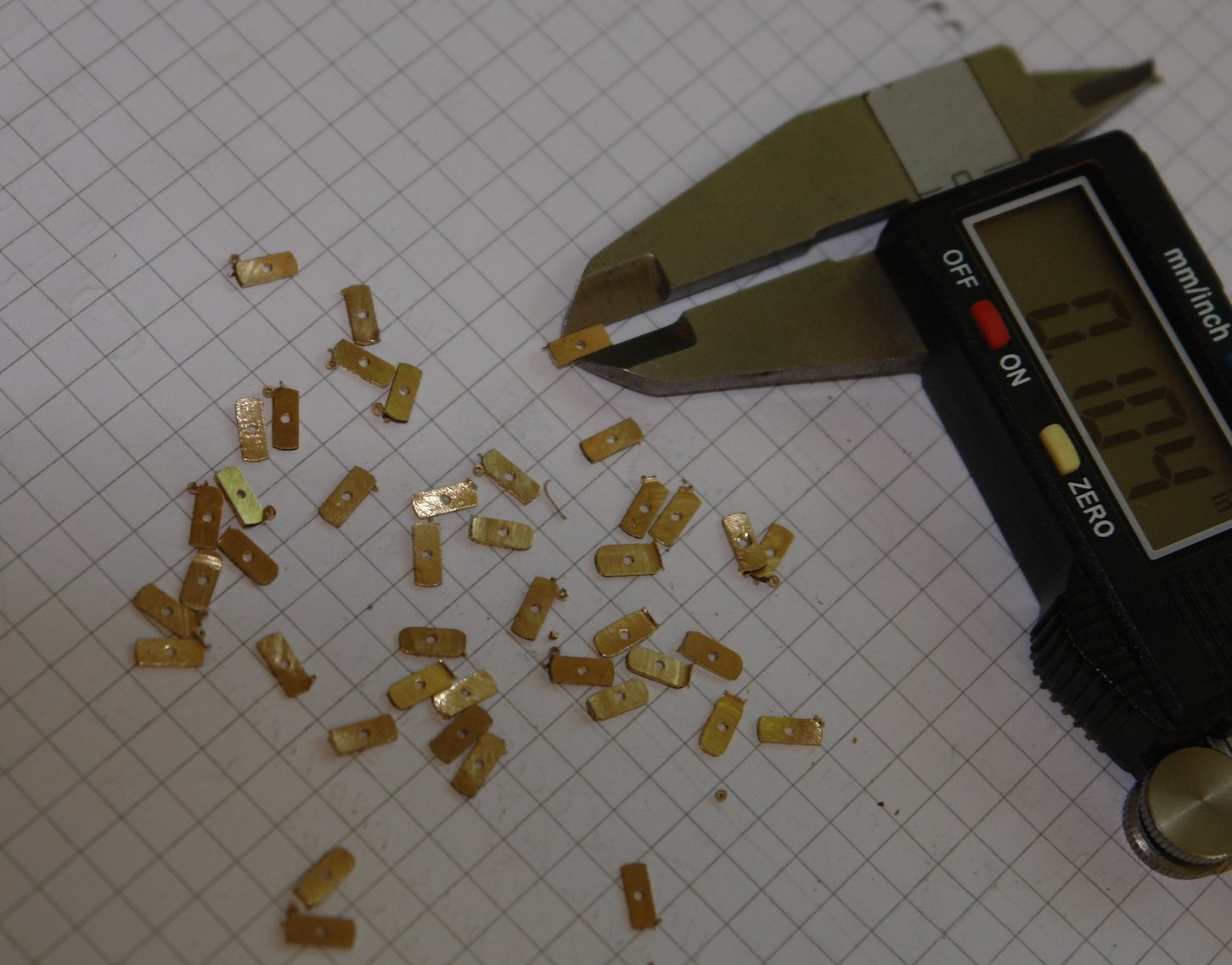
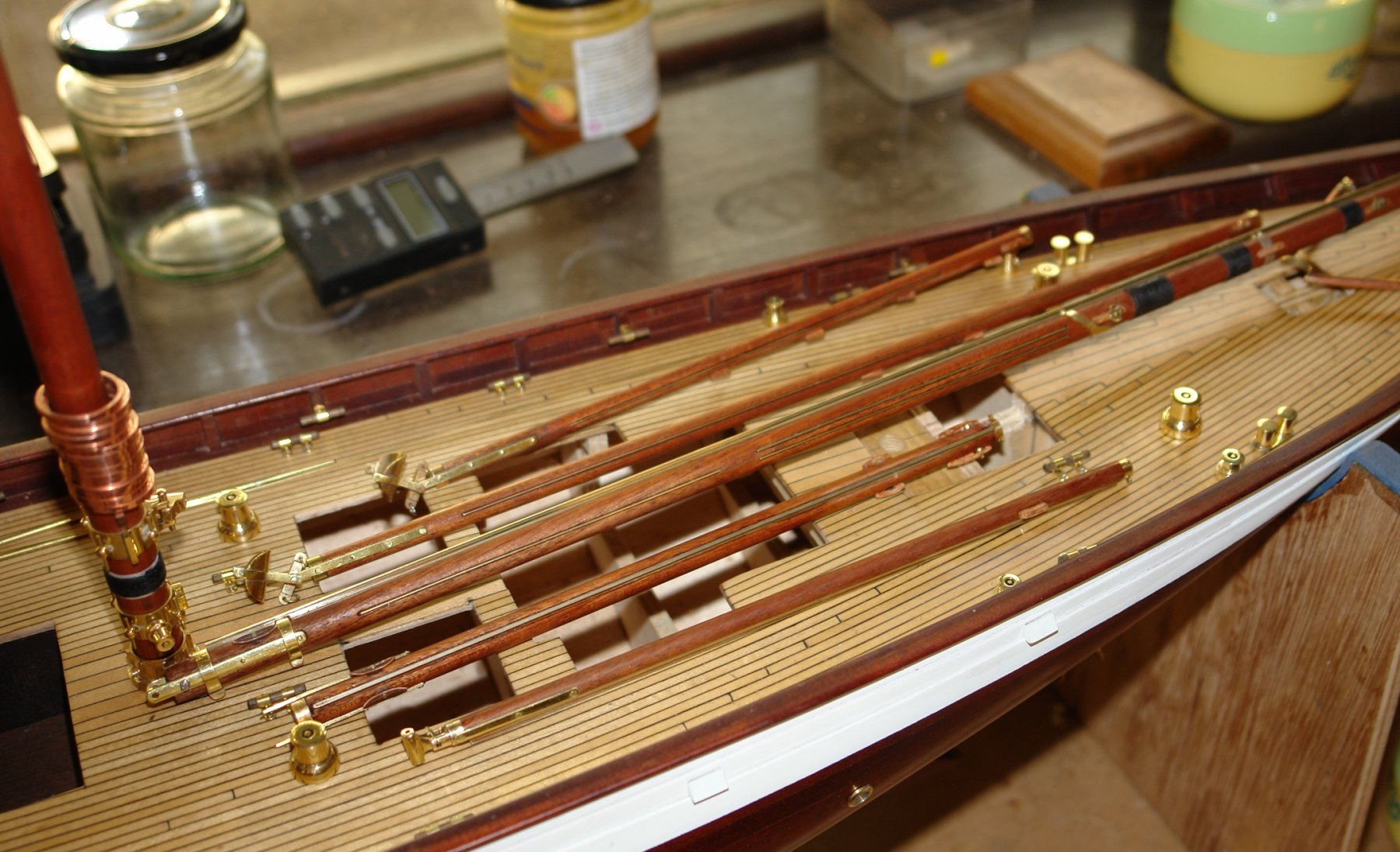
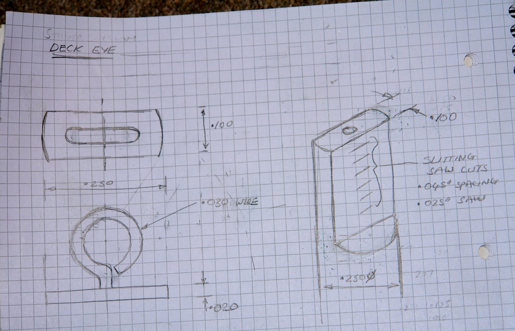
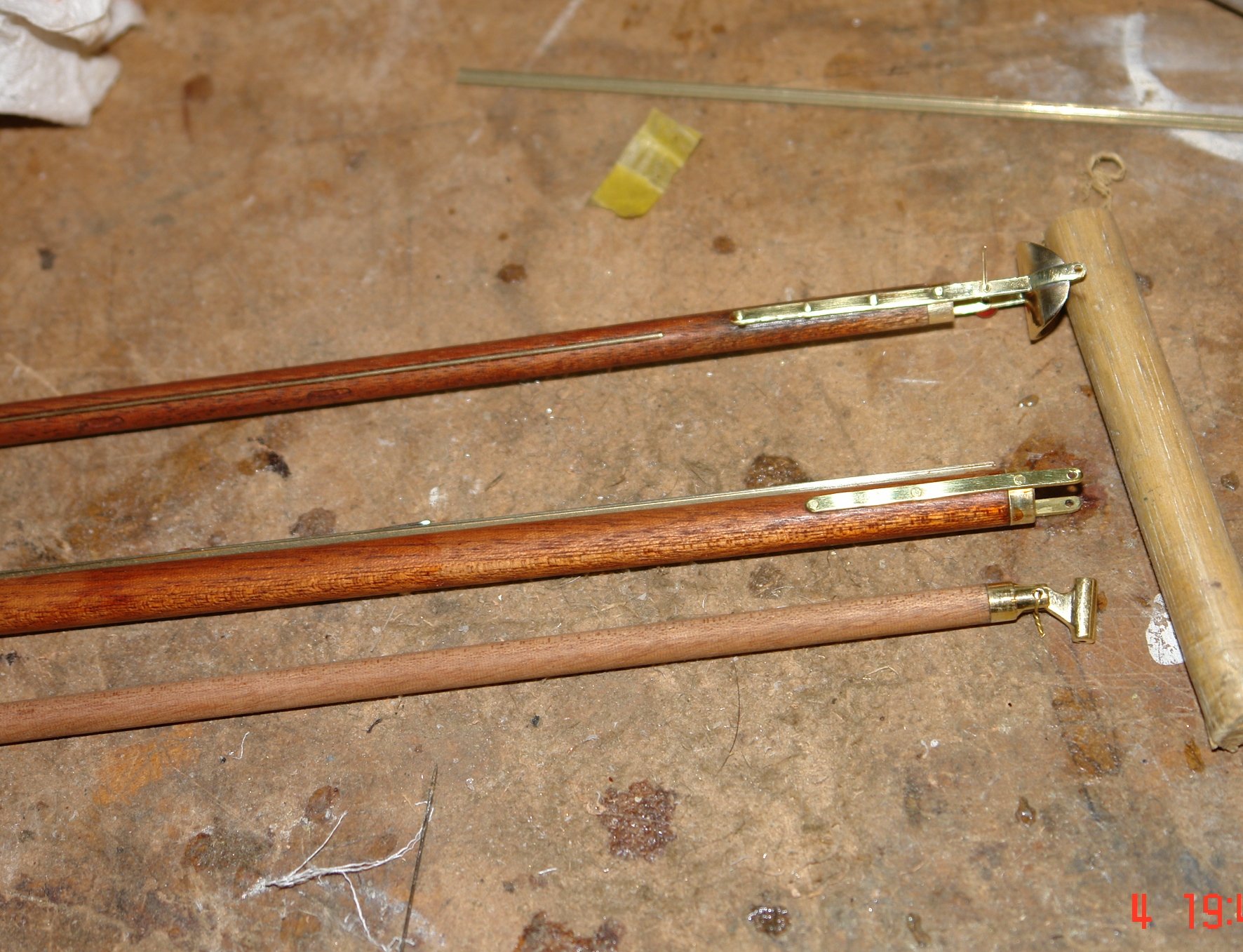
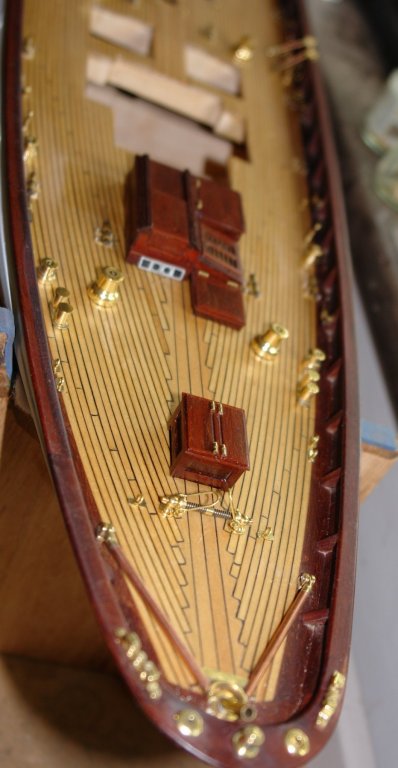
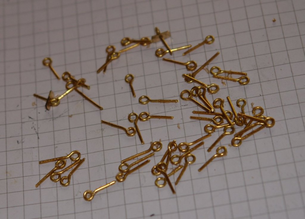
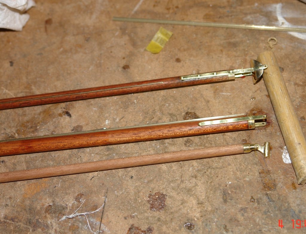
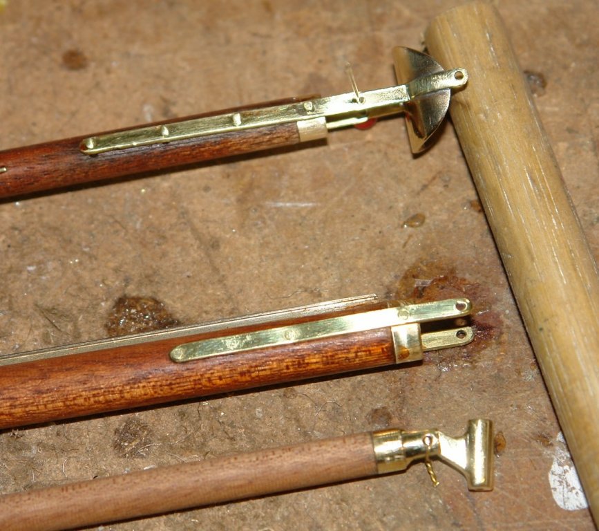
Nils / John / Richard - thank you. Today:- A quick paint job followed by a day of small part production. The deck is festooned with deck eyes - over 50 in total - today I made all of them. I wanted to sort out a relatively straightforward way of reproducing consistent version of the mounting foot. The sketch gives the details. I decided to make the mounting foot out of 1/4" brass bar, drilled with a central hole and then thinned to .100" on the mill. The feet were then sliced off .020" thick using a .025" slitting saw, again mounted in the mill. I then polished each one by hand on a 400 grit diamond stone followed by hand polishing using polishing compound on a MDF board. I now have no skin left on the ends of my fingers but at least I won't leave finger prints when pulling off my next heist. I have seen tools for forming eyes but I don't have one - so it was down to hand production using round nose pliers. in passing I notice the various spars lined up on the deck and thought they made an interesting collection.


-
Nils You seem to make progress very quickly. Do you spend a lot of time on the build or are you training for the model making olympics?
- 2,625 replies
-
- 4
-
-
- kaiser wilhelm der grosse
- passenger steamer
- (and 1 more)
-
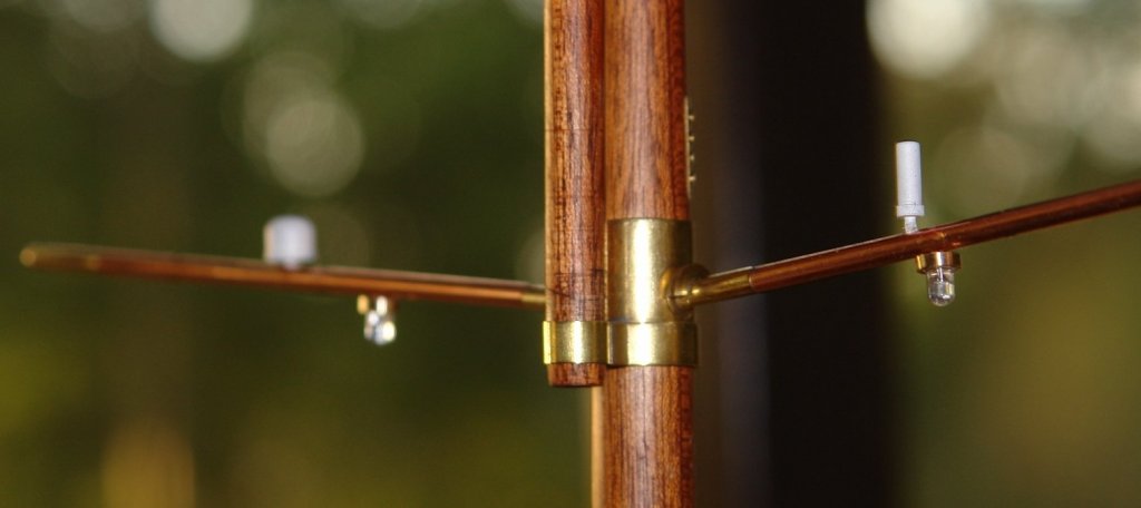
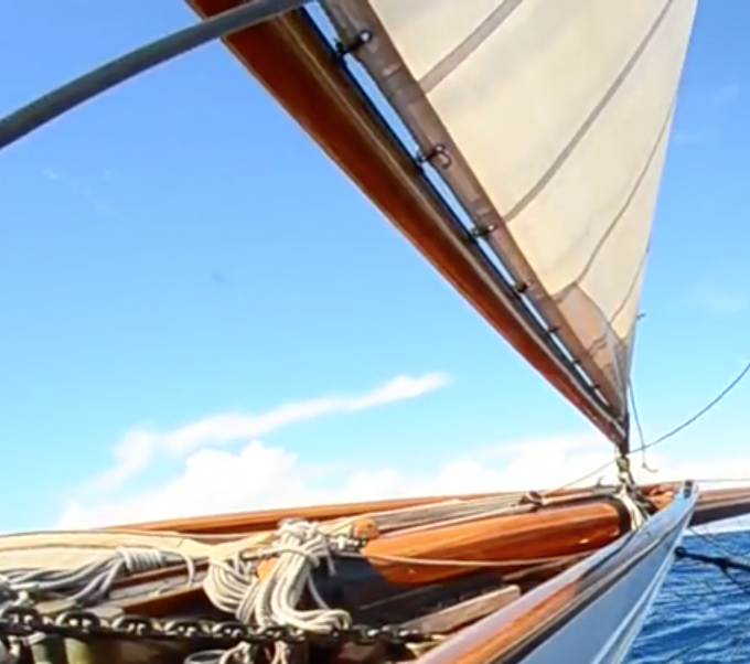
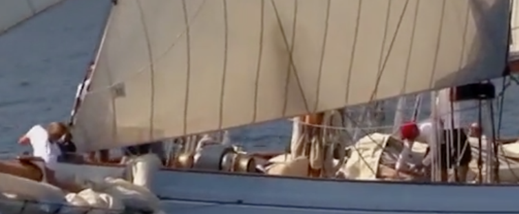
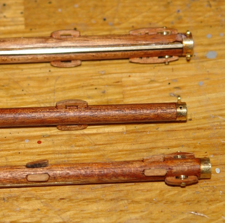
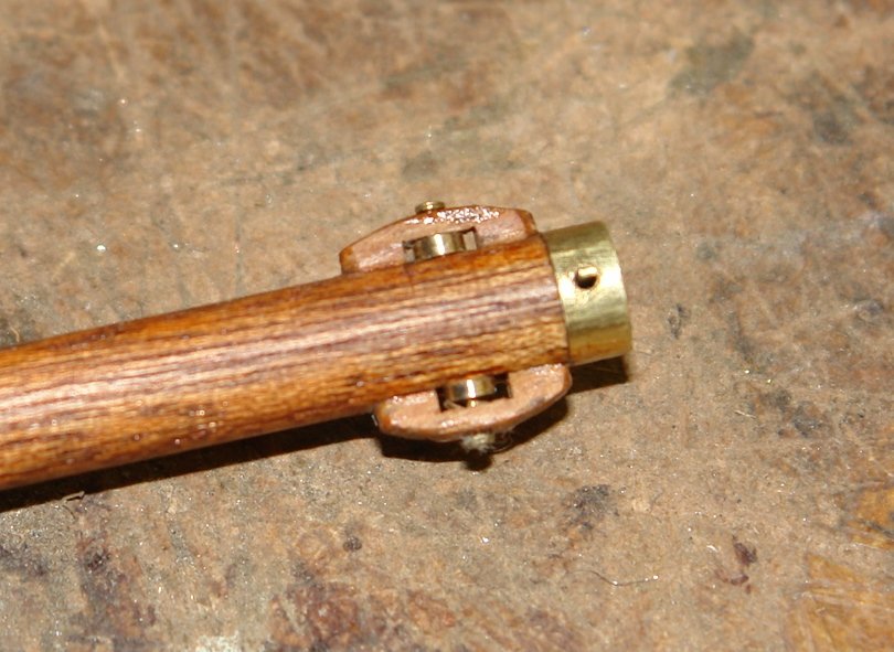
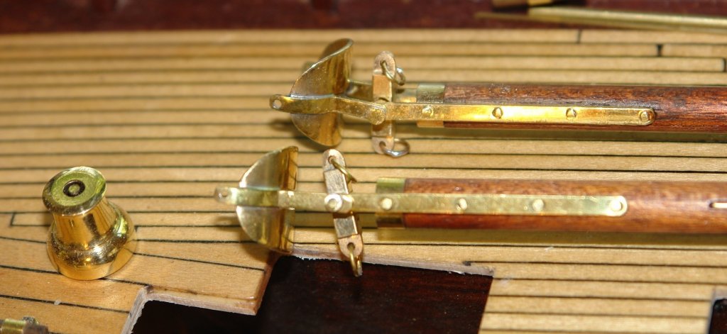
After a few days away I got back to the workshop late yesterday afternoon and commenced the last phase of making the foresail boom and gaff and the staysail boom. The latter item isn't always deployed and I find a lot of photos with it omitted from the sailing rig. Both conditions can be seen in the next 2 photos. I think she looks more interesting with it fitted and this is the way I will go. I made and mounted the various wooden appendages:- Most are .080" wide to give an idea of scale I also made and installed the .035" wide sheaves. This time the track went on easily. Wonderful what taking a little care will achieve. The gaff saddle was also finished with the stirrup installed. For some light relief I went back to the yards and made the lights, GPS antenna, beacon etc. The lights are cut down LED's. I decided not to have working LED lights. I find I hardly ever switch them on and the batteries rot away and make a mess. The antenna / beacon will be painted white.


-
Don Re Bristol Pilot Cutter kit, this may be of interest http://www.kingstonmouldings.co.uk/products.html
-
Greg, thanks for the feedback and the doggy advice. Michael & John. Thank you for your continuing intrerest and comments. Richard. The problem with the track was all of my own making, I was a bit pushed for time so I was rushing. A case of more haste less speed. I had a look at frets on the web and they do look like an interesting resource for the future. The fret domed top wasn't quite what I was looking for as I don't think the flat bottom / sharp edge will work well with the slider design I have in mind - I did the riveting like this - nothing special really.

-
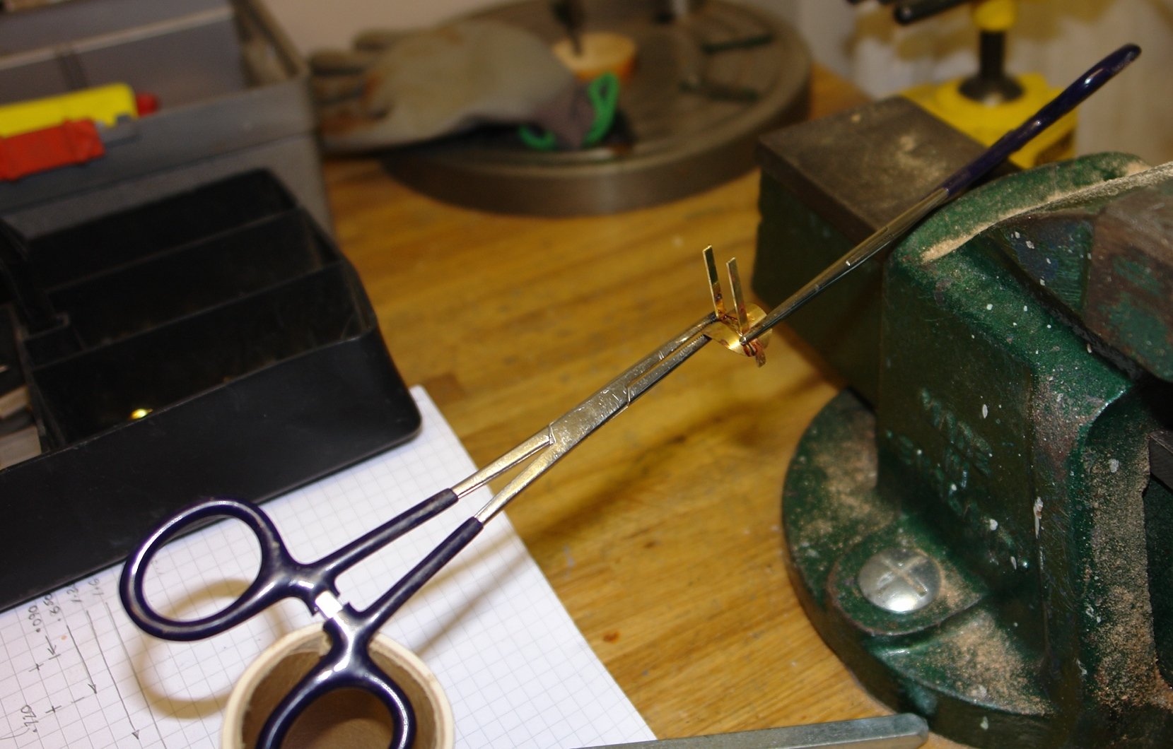
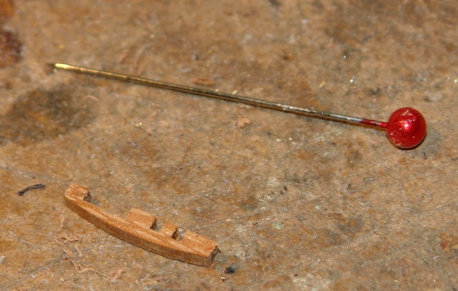
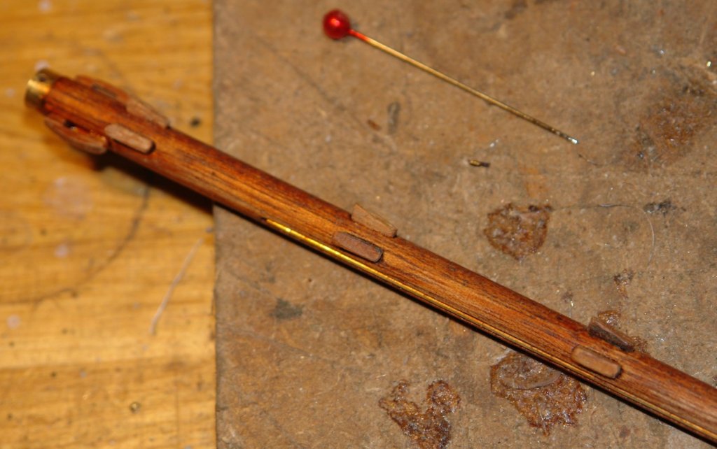
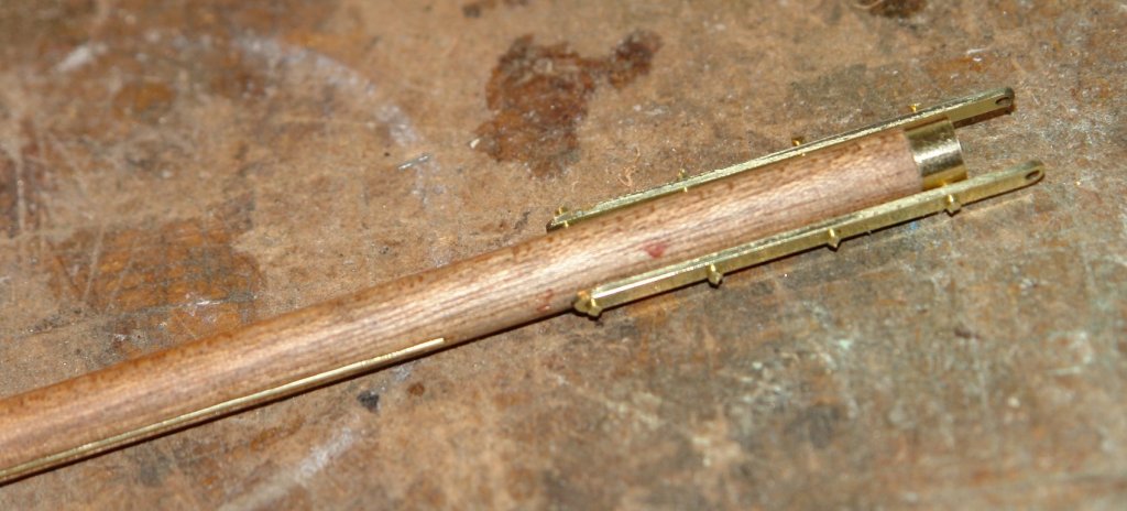
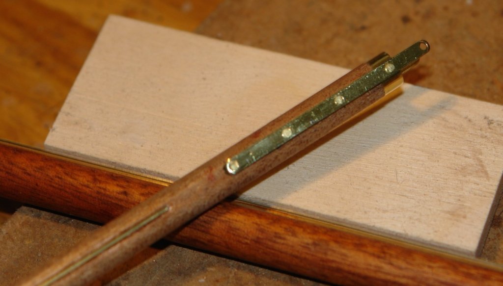
Thank you Richard, for both the build and dog compliments. Thank you Per, and I'll give the bone trick a try. I continue to make progress on the booms and gaffs. The foremast boom and gaff have all their machining complete, the straps for the mast attachments etc are made and riveted in place and the track and rubbing strips are cut and glued with CA. Various wooden fittings (pulleys etc) have yet to be made and fitted. I found the track fitting to be quite a challenge - for some reason it kept going on "squint" and I had to apply heat to break the bond and try again. I did it 3 times in the end - not a good day. The straps were cut from .030" sheet - using a slitting saw on the mill to get them accurate. they are 0.1" wide. The gaff with straps riveted in place and the rubbing strips inserted:- Making the saddle - the soldering clamps work great. Soldering was done using a butane torch. Finally a few views of the various bits. The dressmakers pins give a feel for the size.

- 882 replies
-
- 11
-