KeithAug
-
Posts
3,986 -
Joined
-
Last visited
Content Type
Profiles
Forums
Gallery
Events
Everything posted by KeithAug
-
 Tecko This sounds like a great project. I look forward to following along.
 -
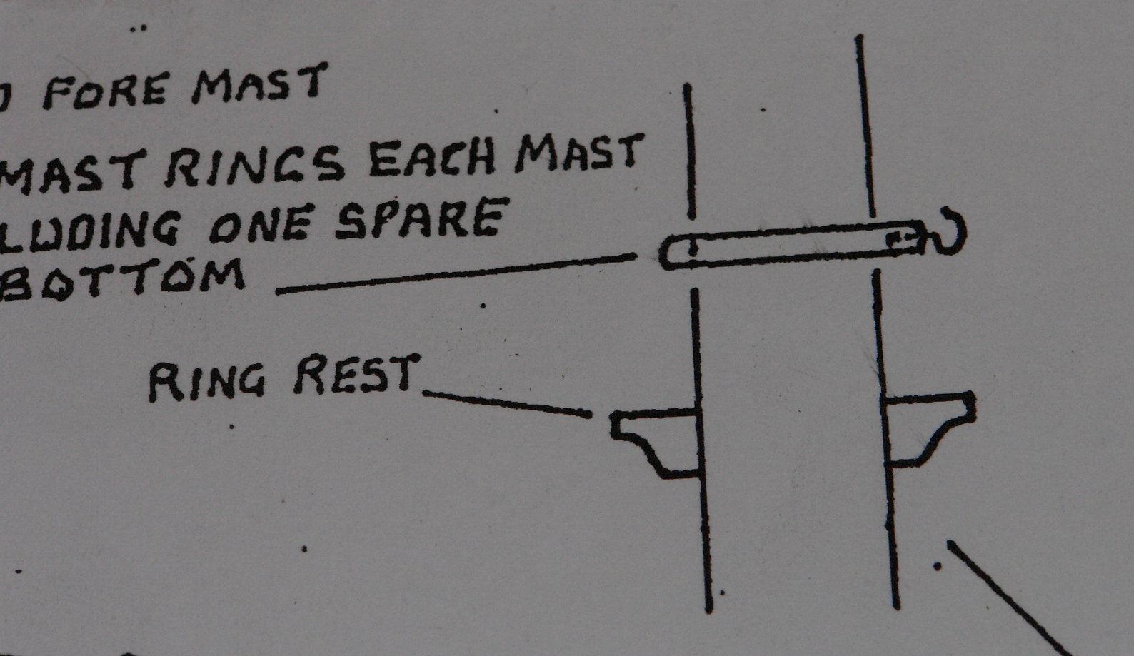
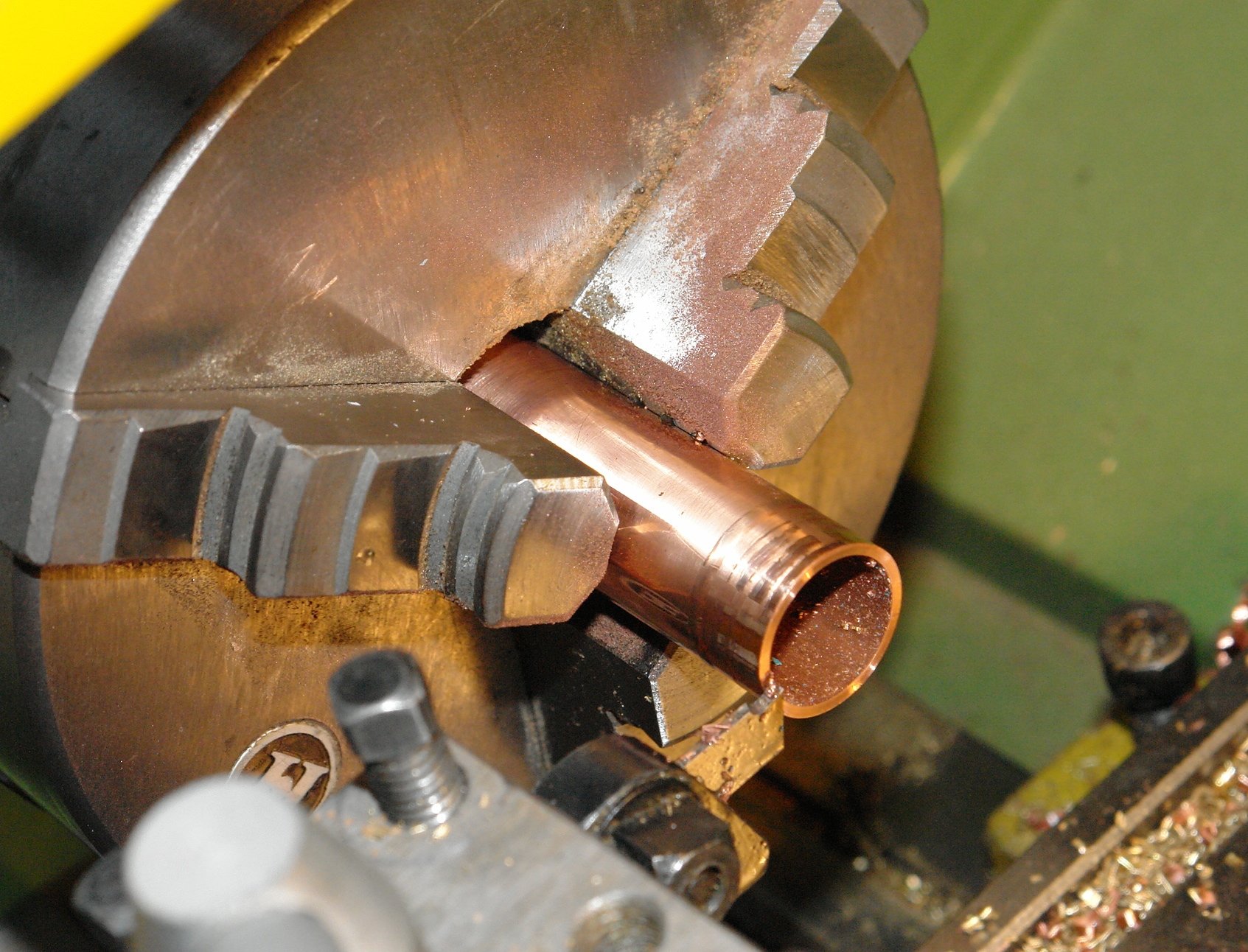
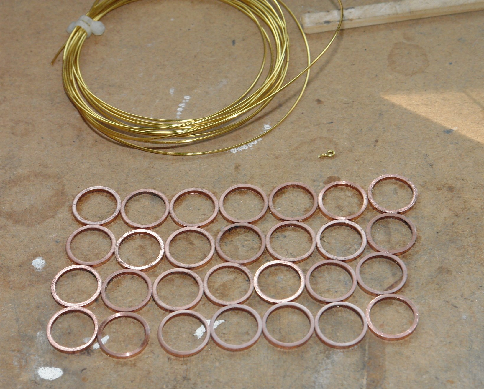
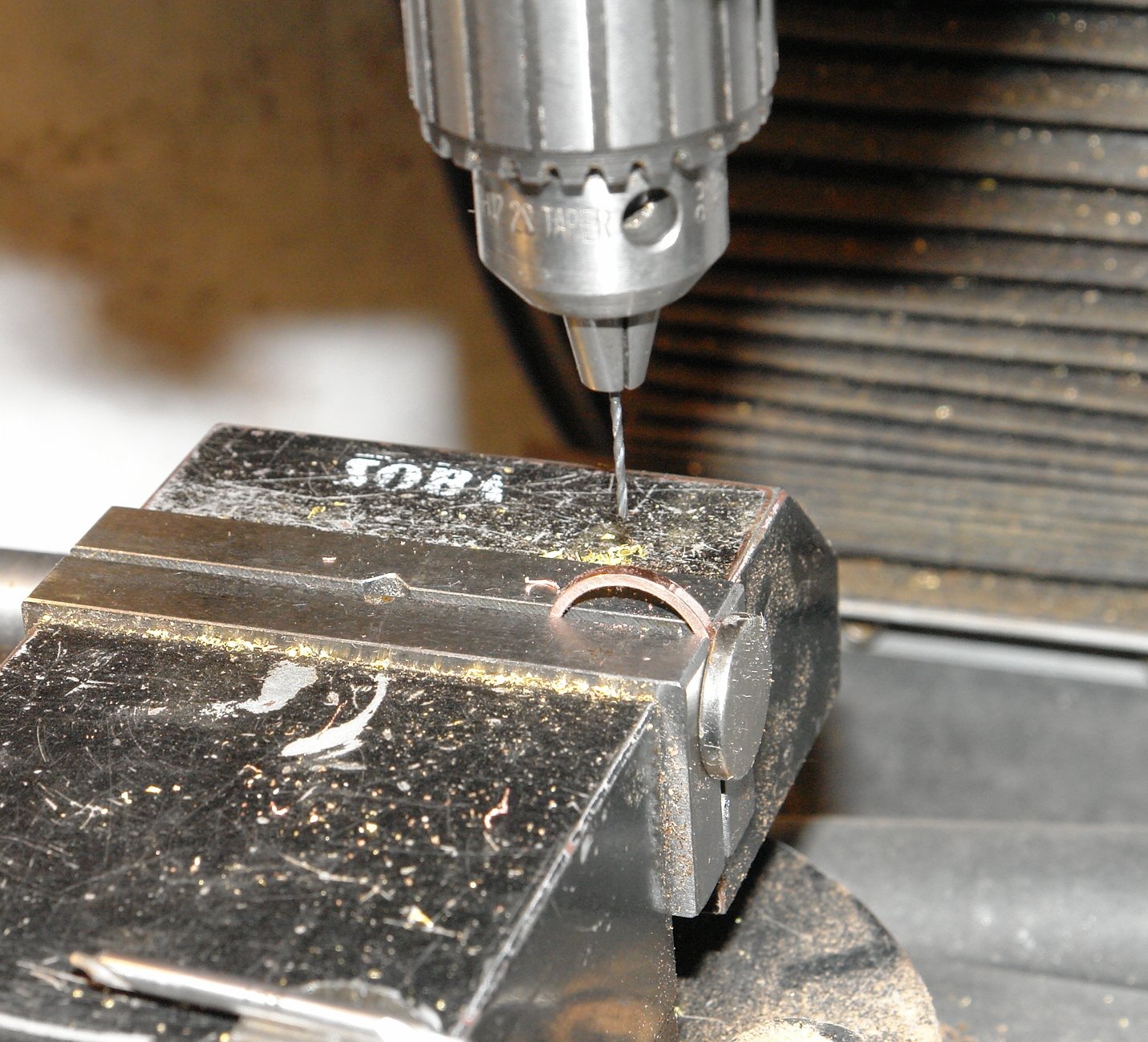
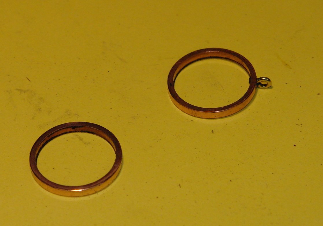
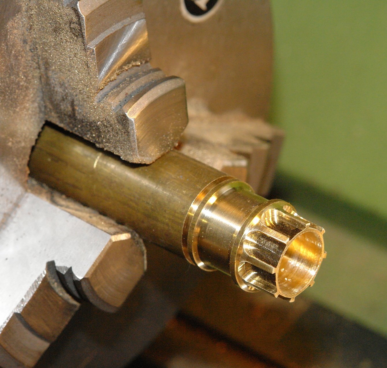
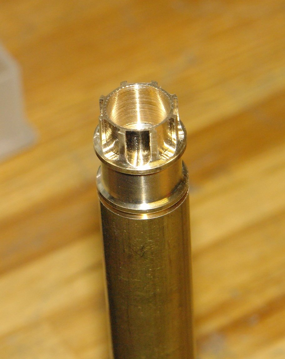
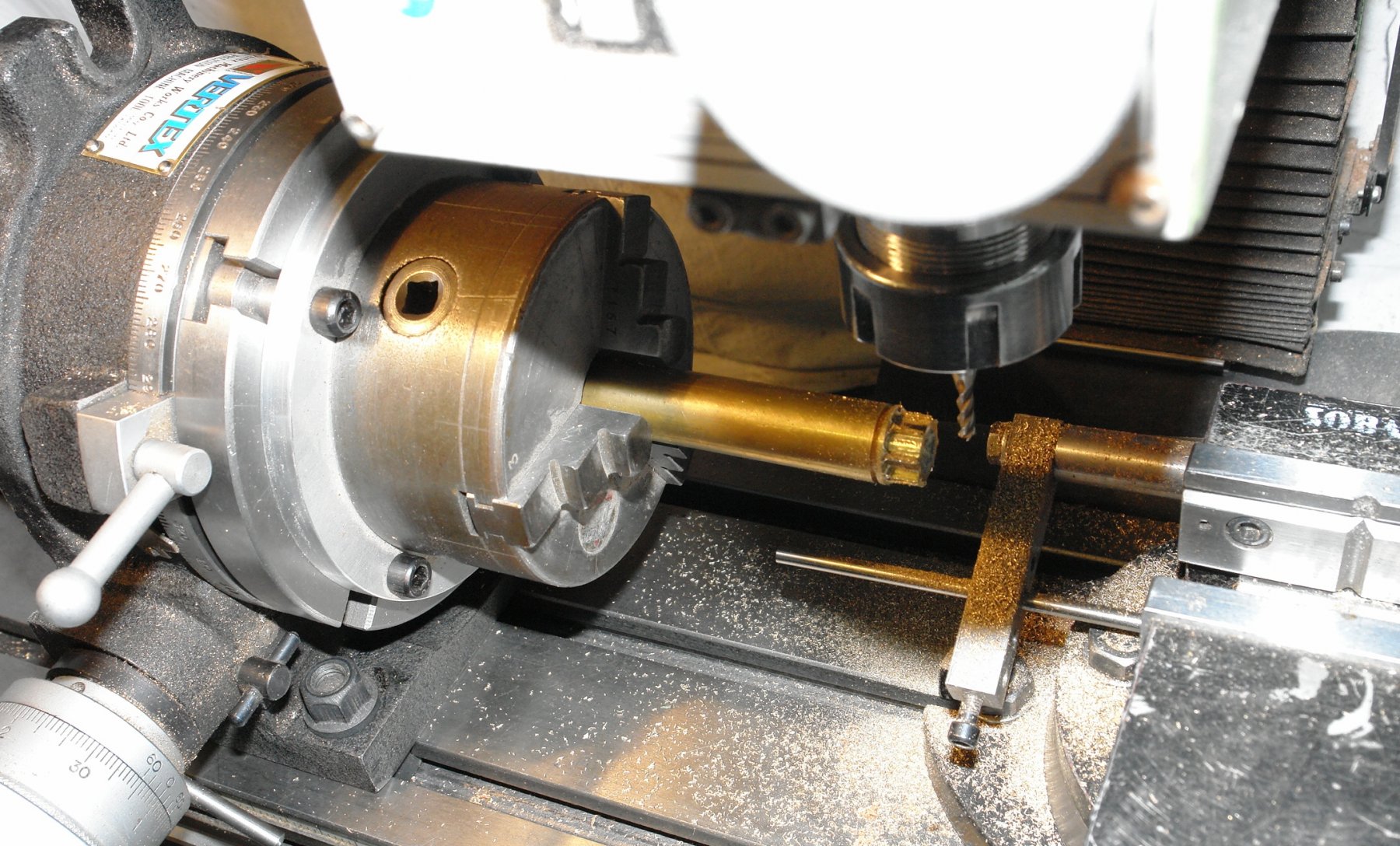
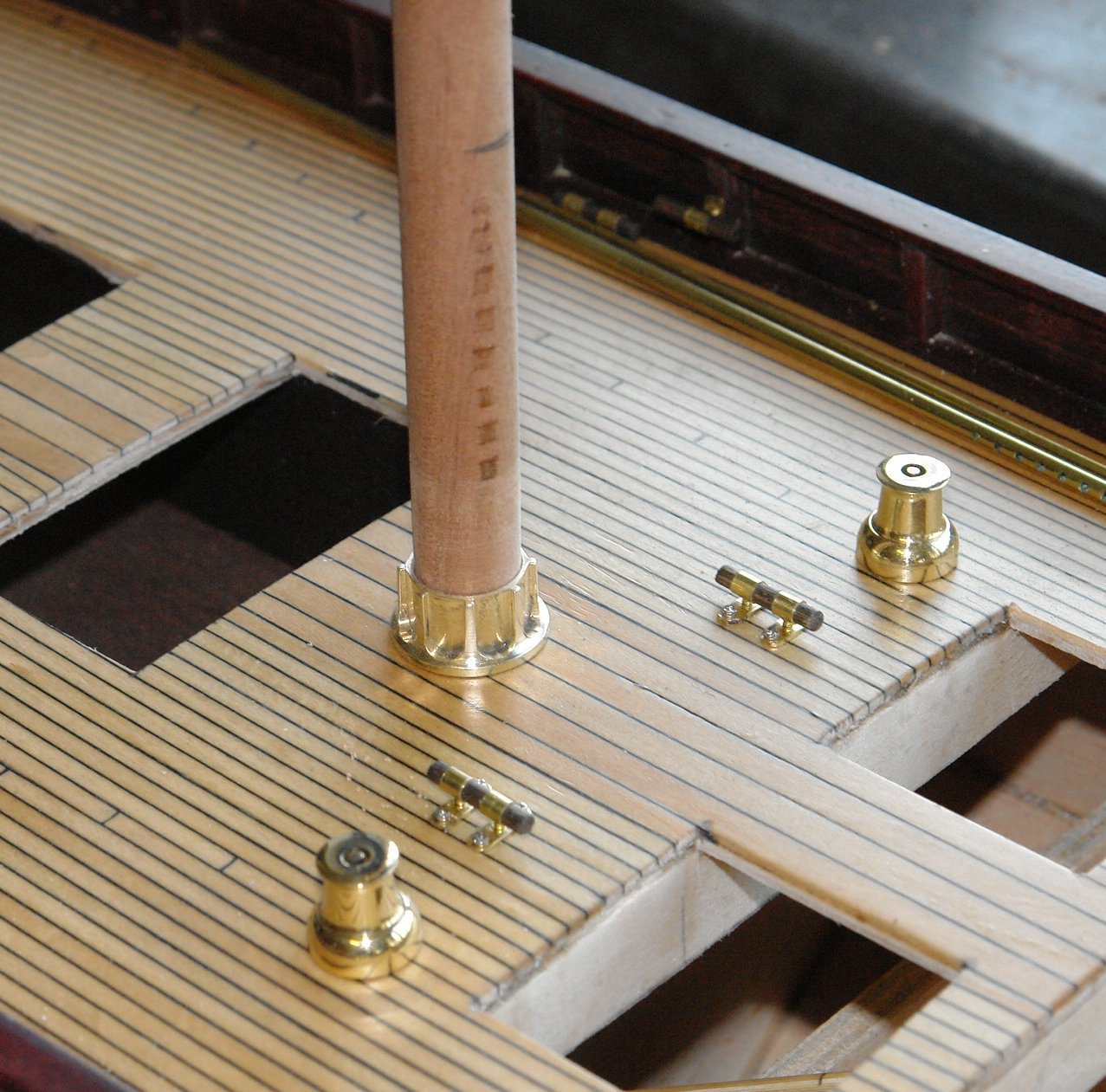
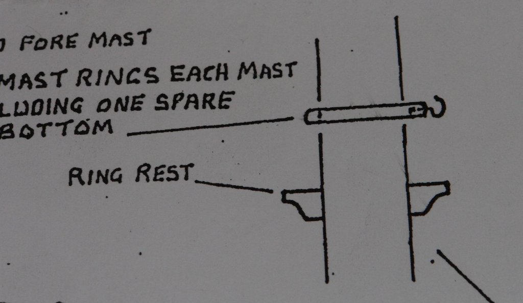
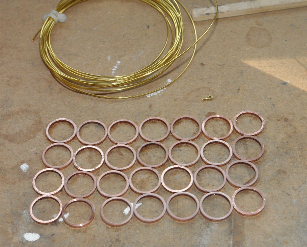
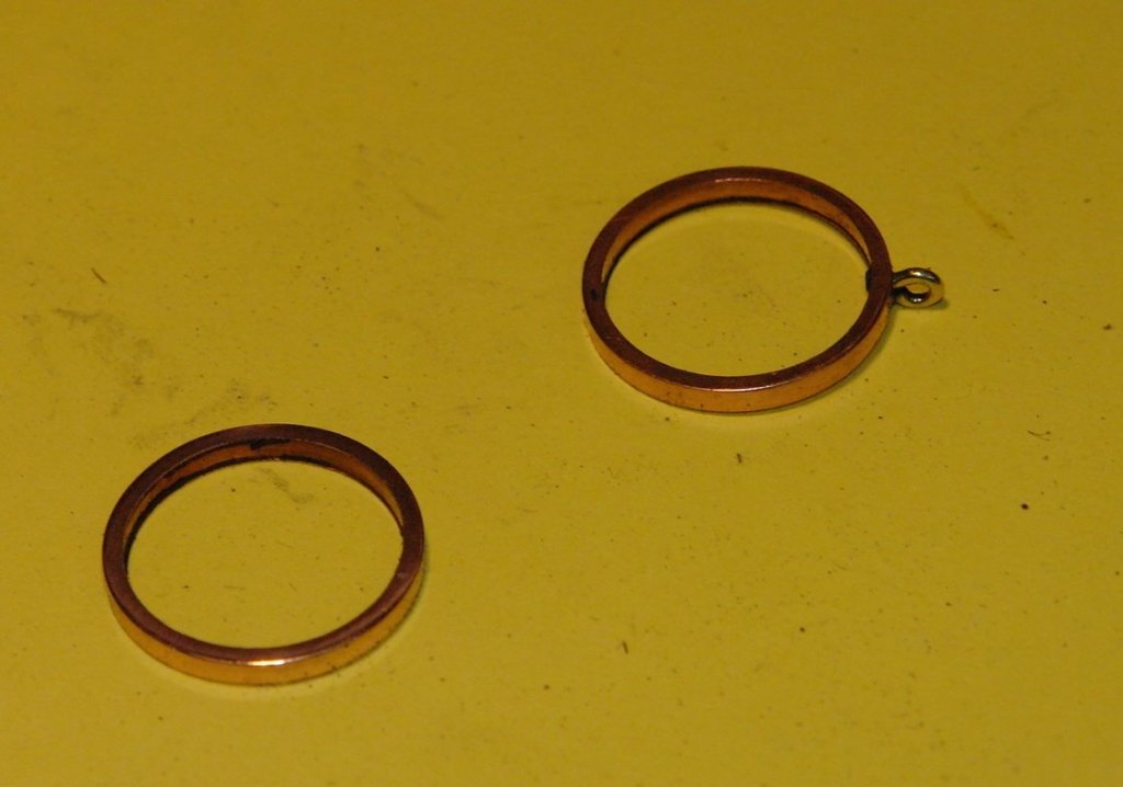
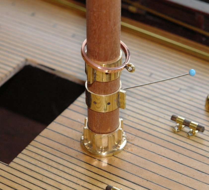
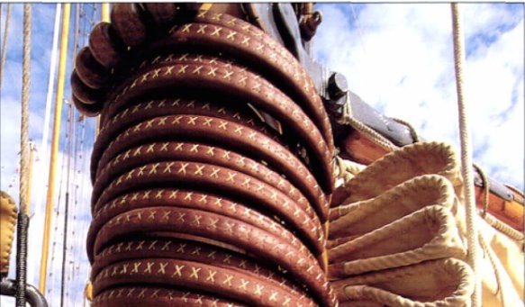
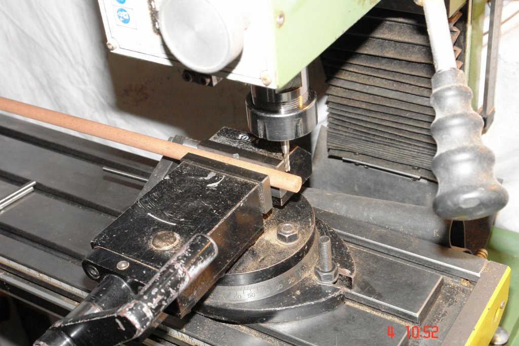
I seem to be in an unexciting phase of the build but time passes quickly. Between the build and sorting out the garden I seem to have little spare time on my hands. I knocked out the rest of the mast hoops. The plans show the following detail with the hoops having a hook for attachment of the sail. I found a thick wall brass tube of the correct size and parted off the rings - 34 including 4 spares (not all shown in the photo). I started to drill the rings and solder on an eye. The mill was set up for a production run - the rare earth magnet on the vice jaws providing the end stop for positioning of successive rings. It was at about his stage I started to wonder why the eye was required so I started to surf the web and after some searching I came across the following (not so good) photo which seem to show the hoops lashed directly to the sail - no eye!!!!!! So the hoops were made with no eye. My fingers got very hot during polishing on the buffing wheel. I am reminded what a horrible metal copper is to machine. Its soft and pushes away from the cutter and then snatches at it. Fine drills are grabbed and break. A material best avoided unless needs must.


-
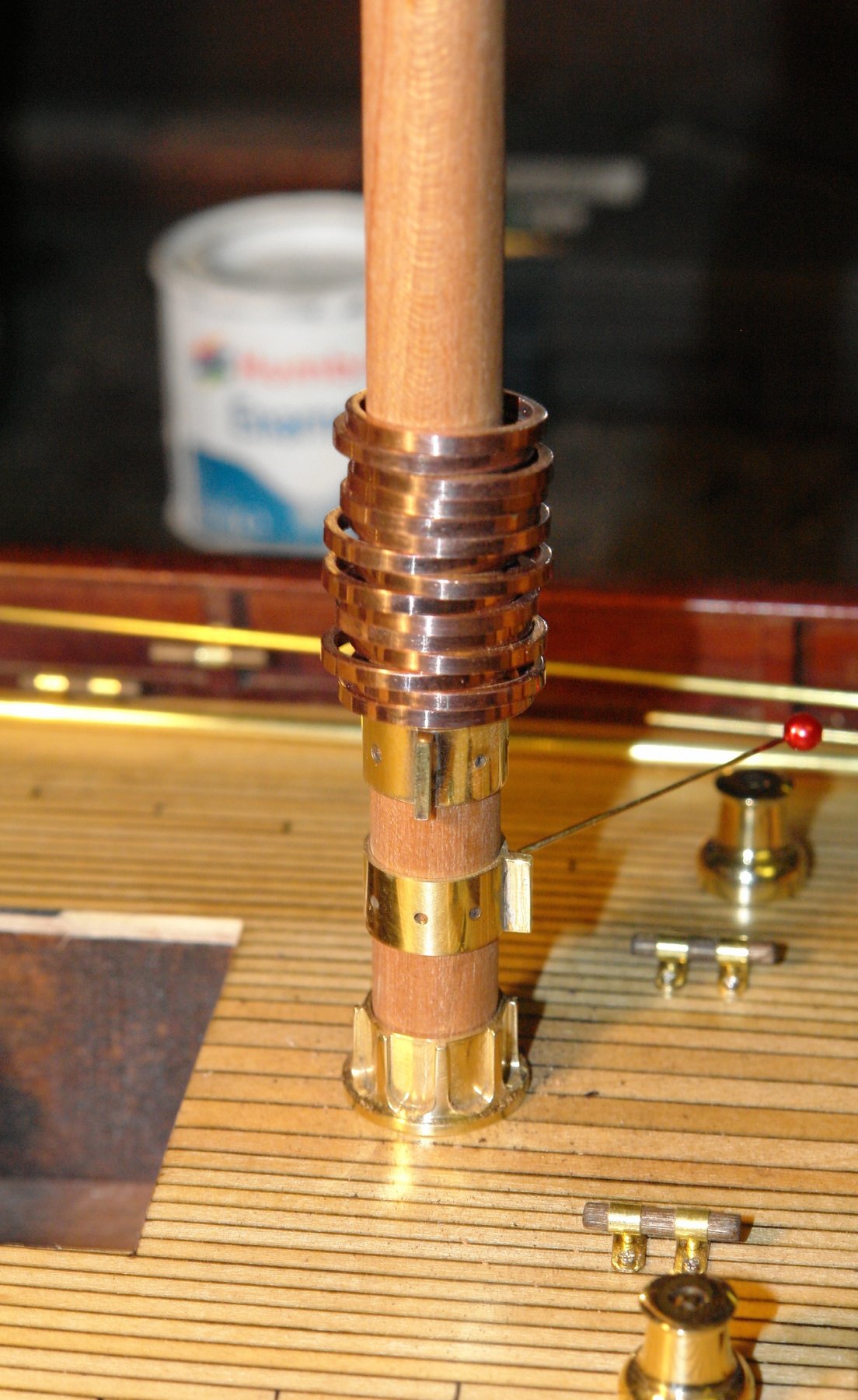
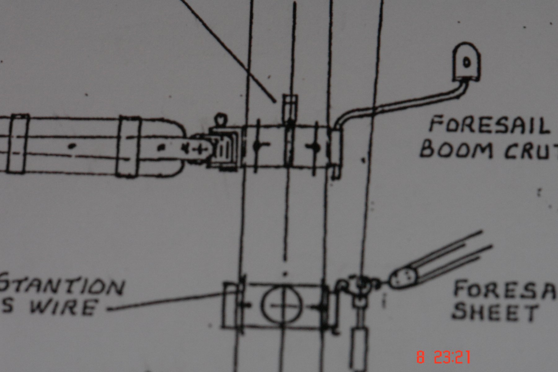
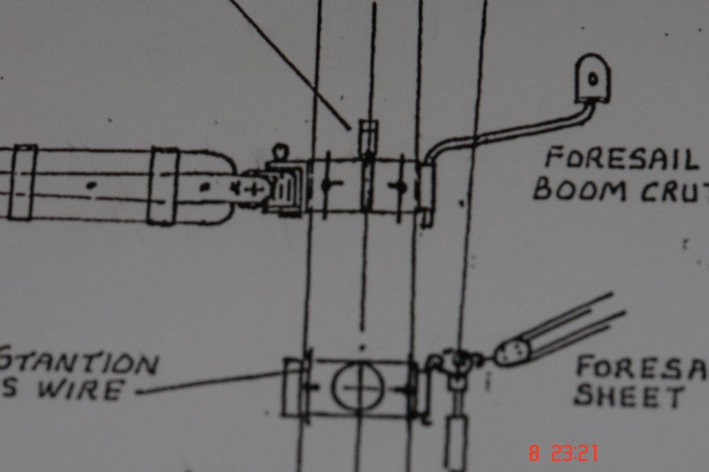
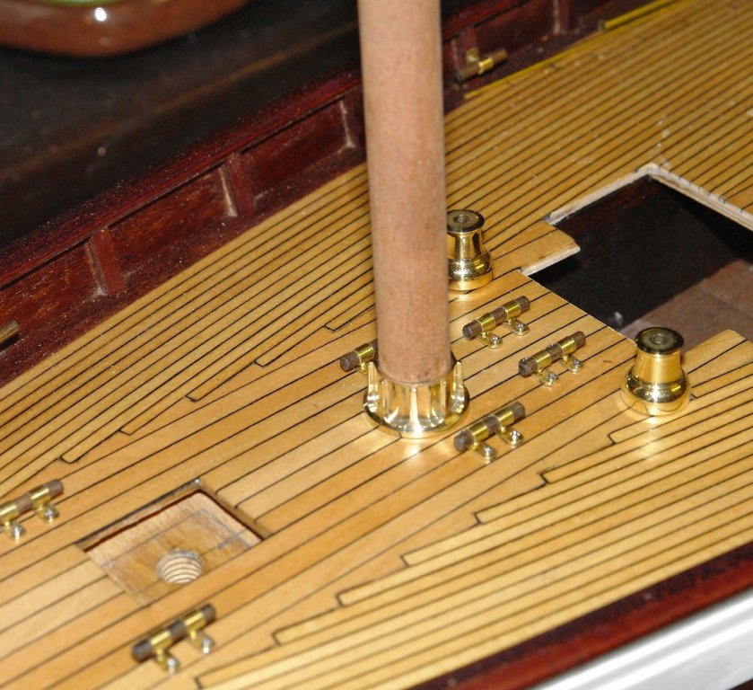
Hi Richard - I took over 20 years to complete one model. So you have 6 years left. I have been doing more work on the mast fittings. I am well on with the upper and lower spiders for both masts. I have been simulating flange details by soldering on webs. I still have to make the mast bracket part of the gooseneck. I didn't have the right size of milling cutter but I now have one on order. The plans continue to pose issues - the main mast gooseneck bracket is shown with the flanges horizontal and I can verify this from photos. The equivalent fore mast bracket is show vertical which seems illogical and unfortunately I can't find a photo of this detail. The fore sail boom crutch (above) is also nothing like the real thing and its things like this that causes me to lose confidence in the plans. I think I am going to ignore the plan and make both horizontal. (Any views welcome) The mast hoops on Altair (15 per mast) are made of wood - but covered in leather. At scale size the hoops are .750" diameter and about .075' wide. I had a look at coiled paper and coiled wood shaving methods of making the hoops but given the finish is leather going down these routes seemed a bit irrelevant. Looking at the photos it struck me that the finish was quite close to what you get from tarnished copper. About 3 years ago I made a steam engine for a paddle steamer that never made it to production. Some of the parts were made form copper and comparing the engine with the photos gave me confidence to go down the copper hoop route as to my eye the colour match was almost spot on. I will just have to wait 3 years to get the correct effect. The first of the photos in this post shows one hoop in place - I later threw this one away but I'll cover this in a later post.

- 882 replies
-
- 11
-

-
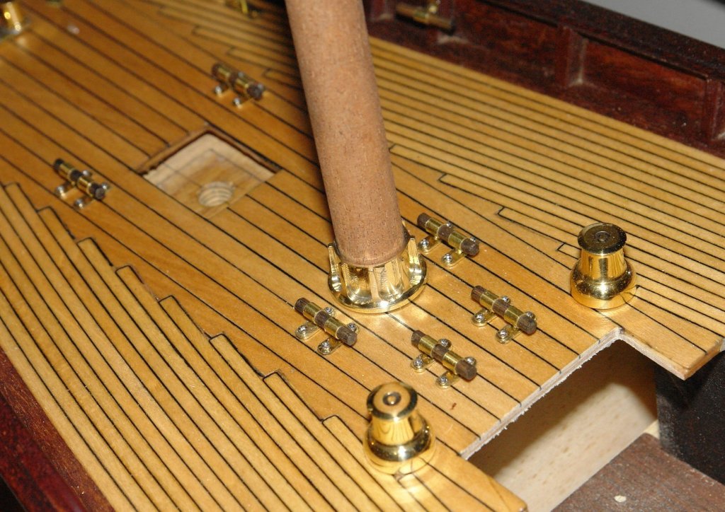
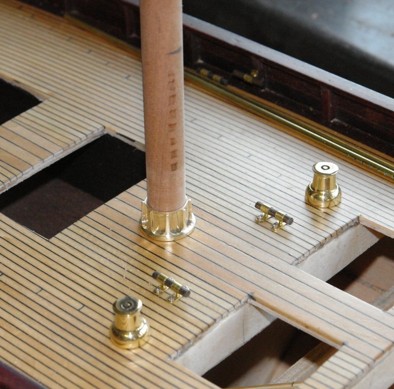
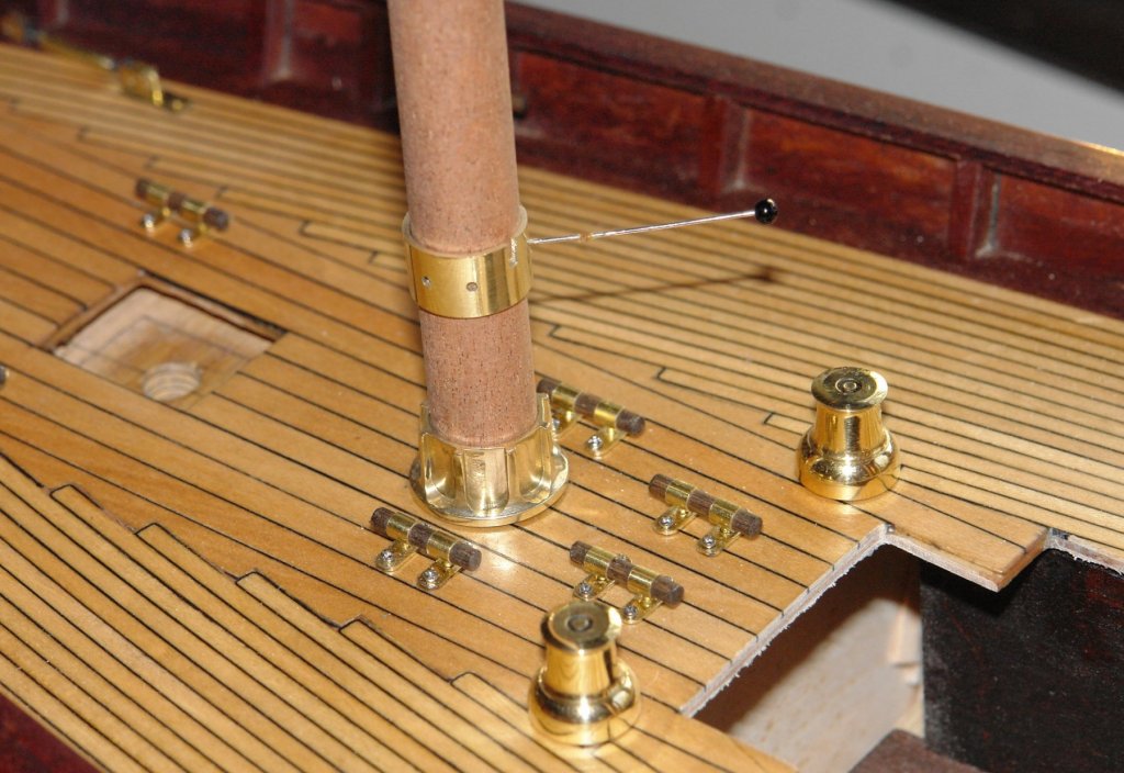
Richard Thank you. I quite like yachts - the lines are elegant and the planking has less severe curves than many vessels, hence its easier to produce a reasonable result. I am a little surprised the more builders don't build yachts before moving on to something more challenging. I did a years machine training when I stared my apprenticeship and then did no more for 44 years. Many retirees seem to start using machine tools when they retire and quickly become proficient - helped by many good you tube videos. As you have used lathe I don't think you would find learning milling would be a problem. Today I started on the mast fittings. I think this will be a topic for some time. Altair has a waterproof boot between the bottom of the mast and the deck. This covers the reinforcing ring at deck level. The shape of the reinforcing ring gives some definition to the canvas of the boot. I thought It would be worth making a reasonable job of the reinforcing ring because the shape was interesting enough to provide a different machining challenge. I turned the basic profile of the 2 reinforcing rings on the lathe before cutting 8 slots on the mill (with a .160" end mill) to represent webs. (The turned profiles are one behind the other on the brass bar in the photo below.) Drilling out the bore was the final operation before parting off. The bar is .750" diameter and the bore is .500'. The height is .375". In the photo below I am milling the slots in the second ring - the bar is held in a chuck mounted on a rotary table. I have included a few shots of the first ring in position on the fore mast. Here is the second ring on the main mast.I made a start on the fore mast lower spider - when complete it will have a couple of winches attached plus some other detail.


- 882 replies
-
- 17
-
-
Coming along well Bob. I must try plating some time - your first attempt seem to have gone pretty well.
-
Herask, Dan, Greg, Richard. Thank you for visiting and leaving such supportive comment. Thank you to everyone else who has "liked" my work. Michael. Its rural West Sussex in spring, the sun is shining, its a balmy 17 degrees and everything is turning green. I assume you are still in the depths of winter? Very soon the village green will be pressed into cricket duties and the two pubs will be serving refreshments to the supporters on their deck chairs. It is quite idilic. Bedford. You flatter me. I spend my time looking at other build logs and feeling I have a long way to go to match some of the expertise on display. I console myself with "the harder I try the better I get".
-
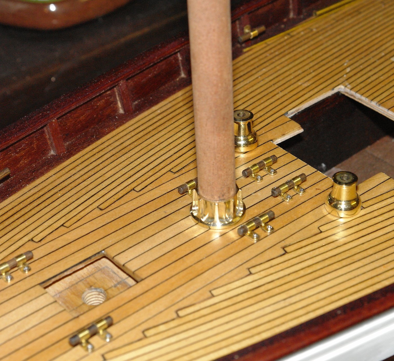
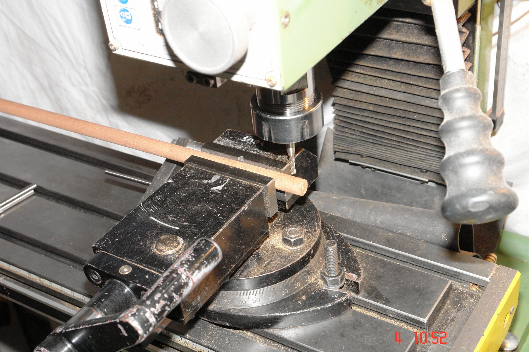
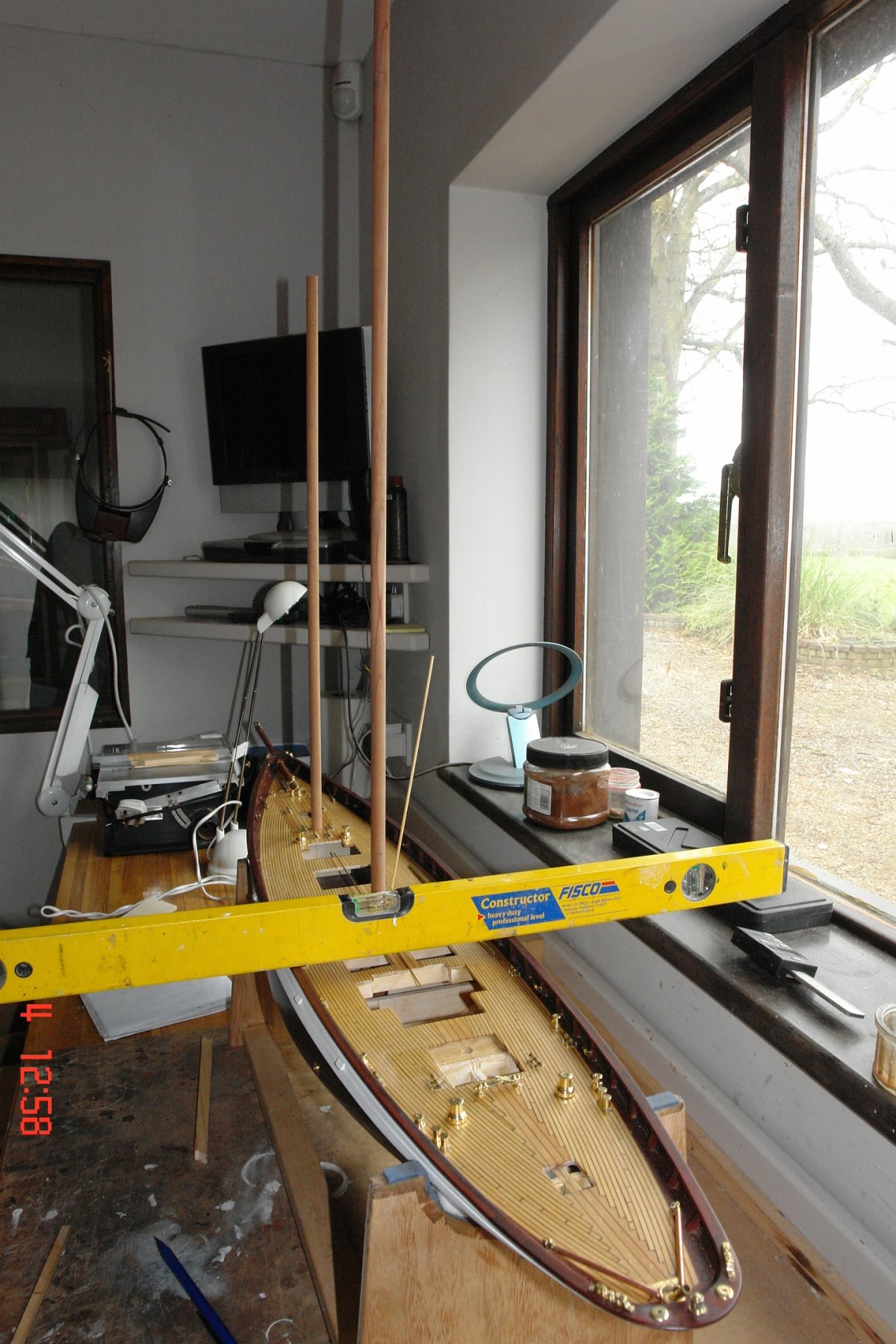
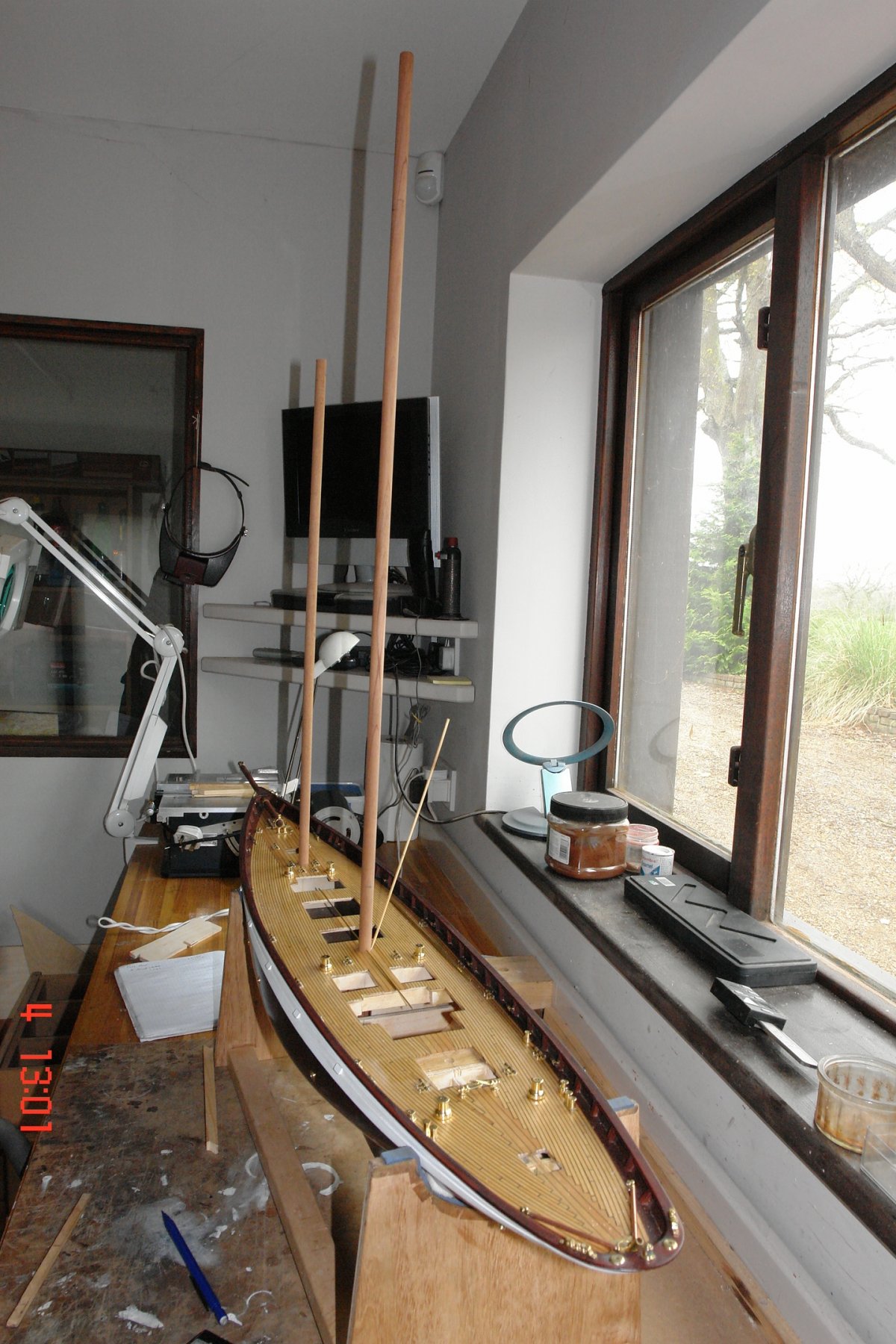
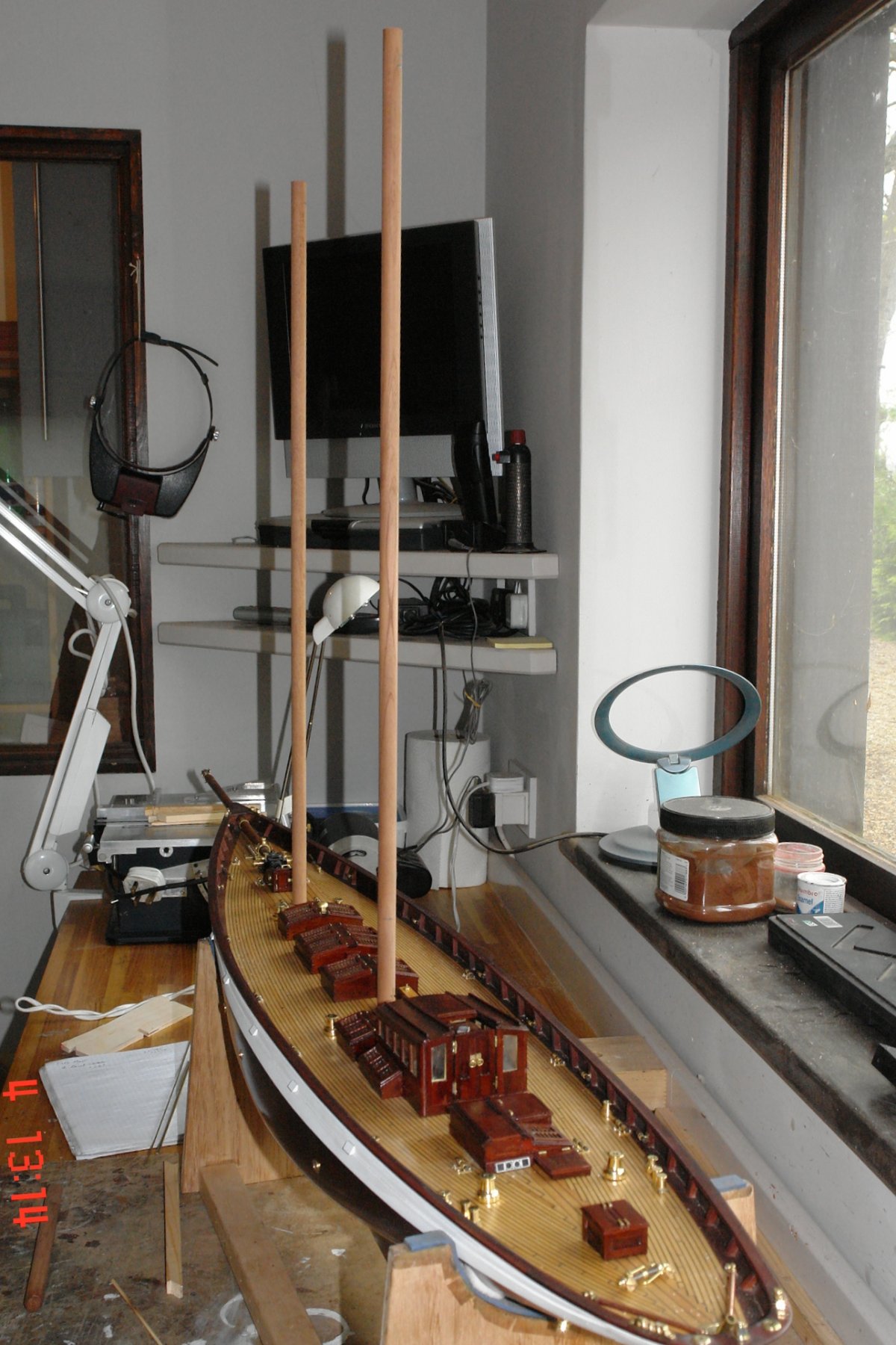
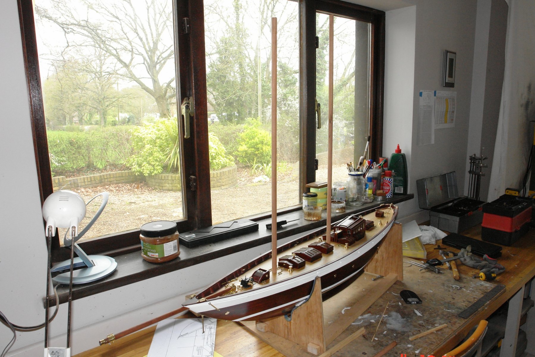
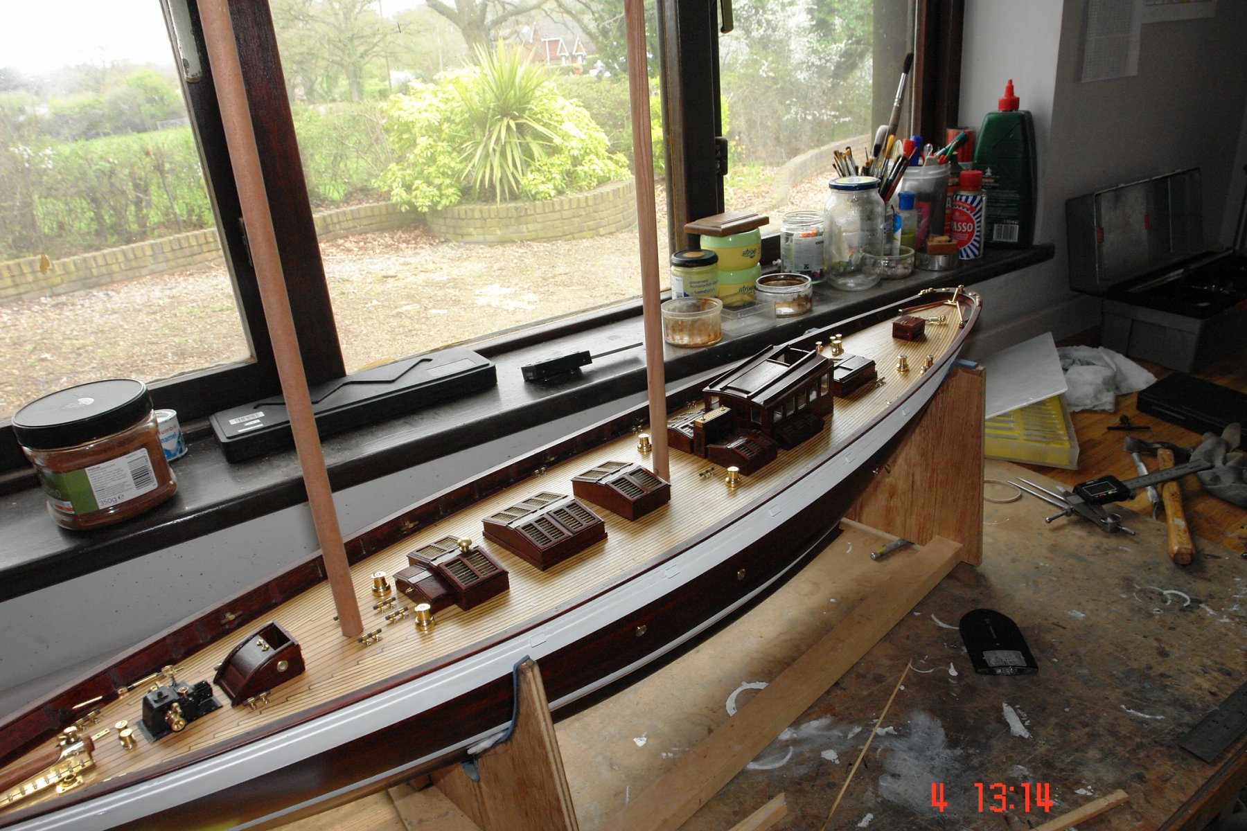
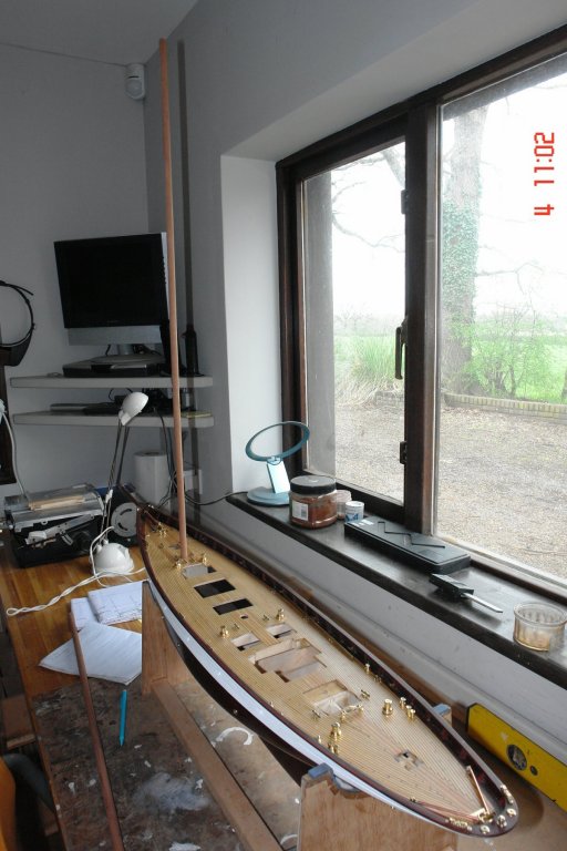
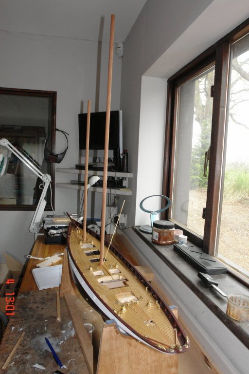
Today I spent a frustrating few hours trying to remember the form of the mast location feature I had cut into keel. For the life of me I couldn't remember. I resorted to peering down the 1/2 inch mast holes cut in the deck, this approach was destined to fail. I then tried to use a skewer to feel the shape, another stupid idea that didn't work. I gave up, had a cup of tea and switched on the computer. Coincidentally it opened on page 1 of my build log and there staring me in the face was the answer. I felt like a complete idiot!!!!! With this vital piece of information I set about milling U shaped slots in the end of two sapele dowels I had purchase for the main and fore masts. Altair's masts are circular and parallel except for the top 1/5. so very little shaping is required. I used the mill because I wanted the slot to be accurately centred so that the masts would be vertical about the centre line and have the correct rake fore and aft. Some time later the masts had been stepped. I use the spirit level to make sure the hull was level and then used precision eyeballing to align the masts with the edge of a window frame. I installed the widow frame some years ago so I knew it was plumb. The rake was checked against a different window frame - spot on at 3/4 inch rake top to bottom. I couldn't resist getting a feel for what she would look like so I temporarily put the deckhouses etc in place. I now have a lot of metal work to do to kit out the masts.


- 882 replies
-
- 18
-
-
Hamilton I frequently used to stay in a seafront hotel on the west coast of the English Lake District. About 20 miles out to sea was a large island called the Isle of Man. One of the hotel owners favourite sayings was "If you can see the Isle of Man it's going to rain and if you can't see it it is raining".
-
Hello Hamilton. I loved your description of your trials and tribulations with your plans. It reminded me of the issues I have encountered. In my case I had to deal with significant discontinuities / errors between adjacent bulkheads. Like you I had cut the plywood before discovering the problem. I have learned not to trust "professional" plans. Good luck.
-
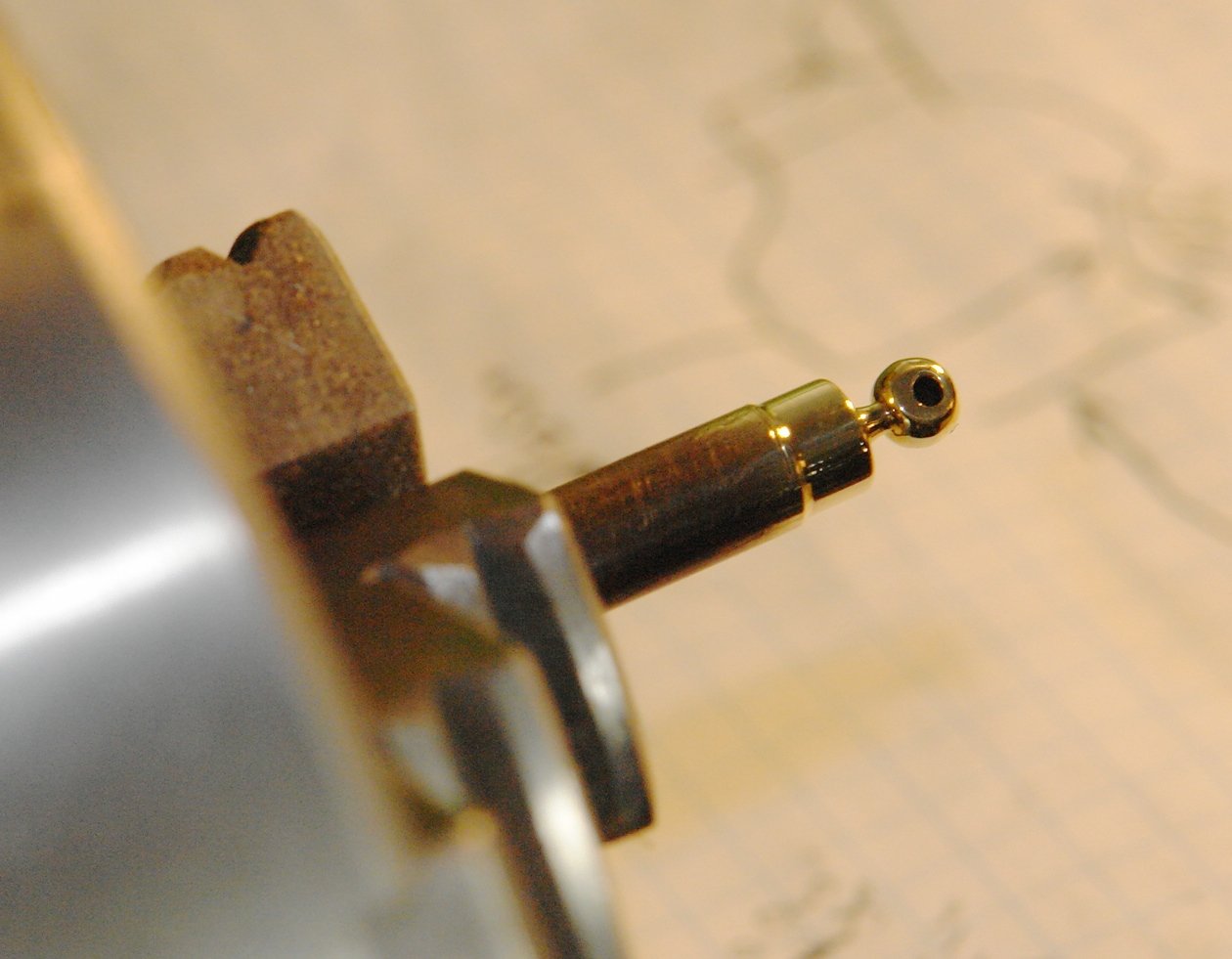
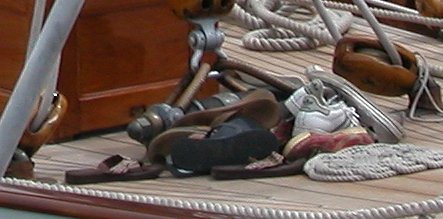
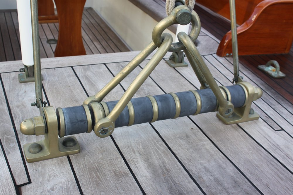
Bill The plans refer to it as a spring horse, which is technically a better description. I don't have a very good photo of it - the one below is the best I could get (obscured by the crews foot ware). It does however show up well in a Vimeo video. It seems these devices were not that uncommon on yachts of this vintage. Here is a better image from a yacht built in 1936, in this case the springs are replaced by what appear to be rubber bushes. In neither case does the device allow much movement save for that allowed by the compression of the springs or bushes. I referred to it as a shock absorber to give an explanation as to what I thought its function was. The only real function seems to be to limit the shock load when jibing.
-
Rob / Per, Thank you for your supportive comments. Per, I struggled for many years without a mill or lathe. Many NRG builders seem to do wonderful work without either. I am however pleased that I made the investment.
-
Per I agree a single plank would look better.
-
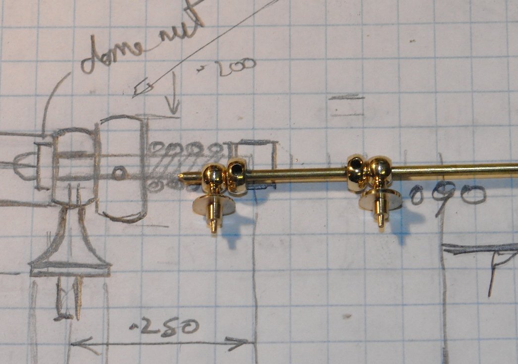
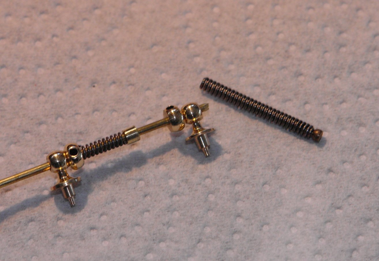
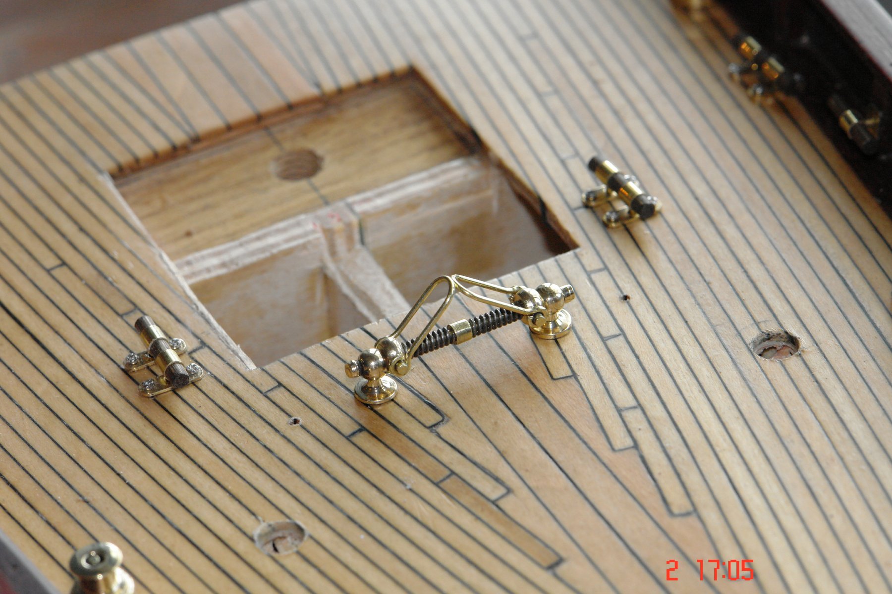
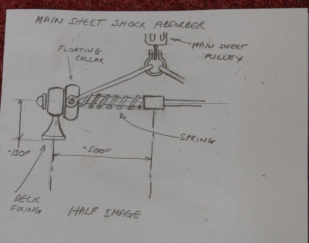
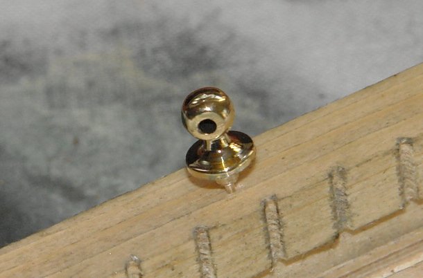
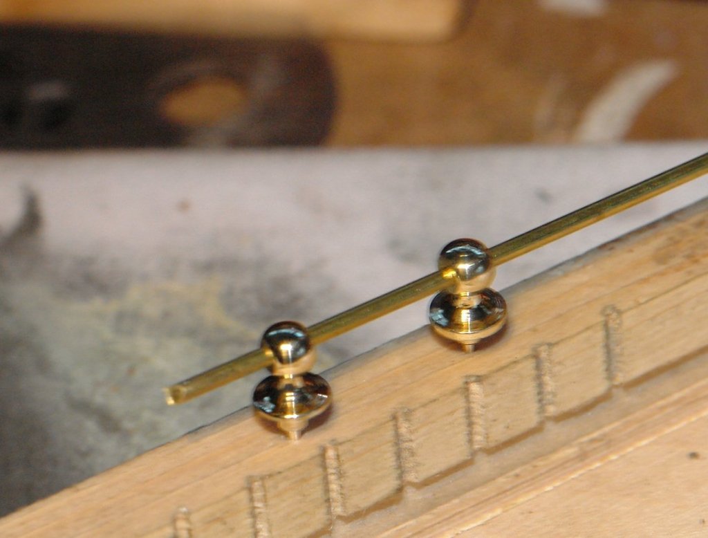
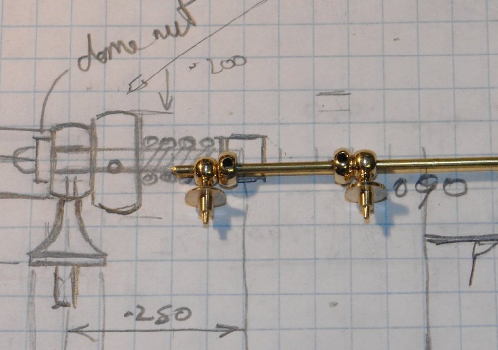
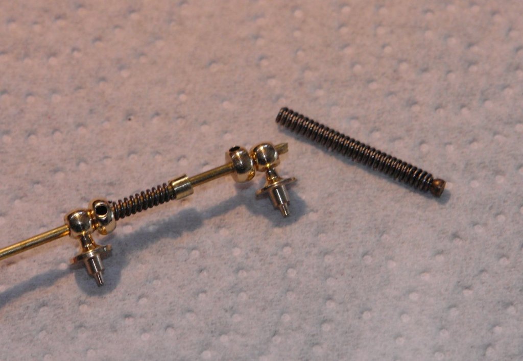
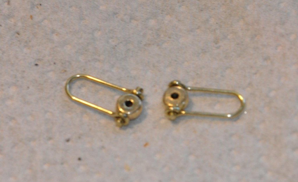
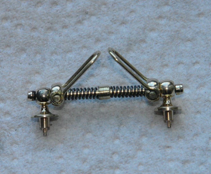
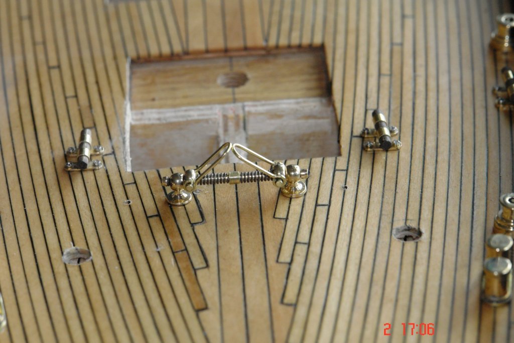
Thank you John. I had been looking forward to a change from doing cleats so I had a go at a bit of detail that I had been looking forward to. The main sheet has 3 attachments to the deck, a single pulley port and starboard and a central double pulley attached to the deck via quite an elaborate shock absorber. Its this latter feature that I decided to attempt next. The sketch shows the detail. The shock absorber has 2 compression springs which close when load is transmitted from the central main sheet block via the floating collars. I thought it would be kind of nice to make a working version. The whole thing is a little over and inch wide and .250 high. The 2 deck fixings were turned from bar and drilled on the mill. I ground a couple of profile lathe tools to assist the task. The floating collars were also turned on the lathe and drilled on the mill. I used the same profile tool that I had used for the balls on the deck fixings. The shaft is .060 wire. The spring was the most difficult bit. I spent ages ferreting through my rainy day boxes until I found something that I could butcher. The floating collars are attached to the block shackle by 2 large U shaped connecting brackets. The brackets pivot on pins protruding from either side of each collar. Nuts on each end of the shaft complete the assembly. Once again the plans are not great and show the shock absorber mounted in the wrong position. The internet saved the day.


- 882 replies
-
- 14
-
-
Thank you for the info Michael - Ill do a bit of reading up.
- 749 replies
-
- 3
-
-
- albertic
- ocean liner
- (and 2 more)
-
Fantastic job Kees. You would never guess she wasn't real. Now all you need a lot of very small fish.
- 434 replies
-
- 4
-
-
- pelikaan
- beamtrawler
- (and 2 more)
-
Michael. I am pretty basic with my soldering. Just an electricians soldering iron with on / off control. I realise I need something better. Do you have any reccomendations please.
- 749 replies
-
- 3
-
-
- albertic
- ocean liner
- (and 2 more)
-
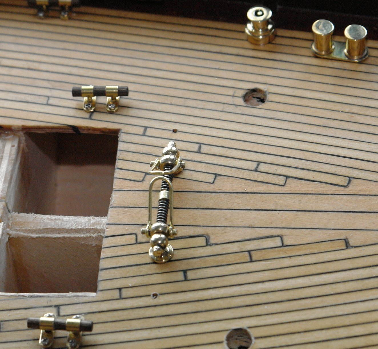
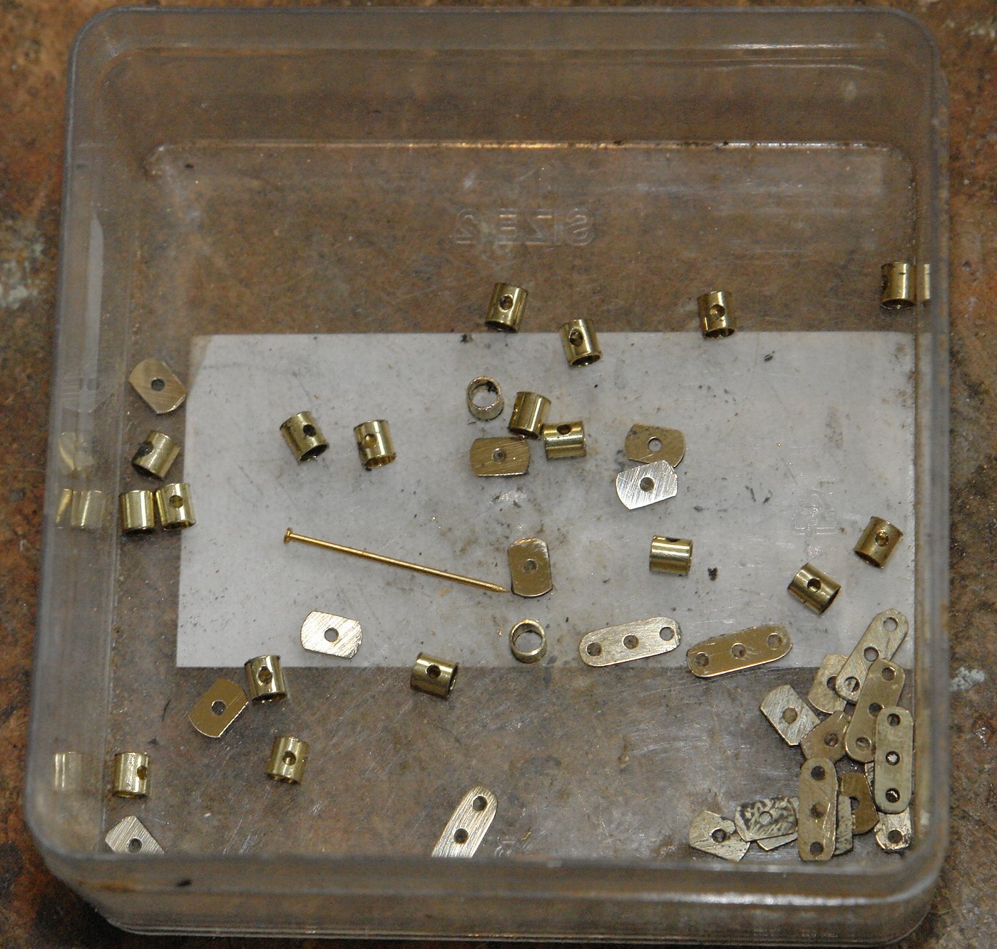
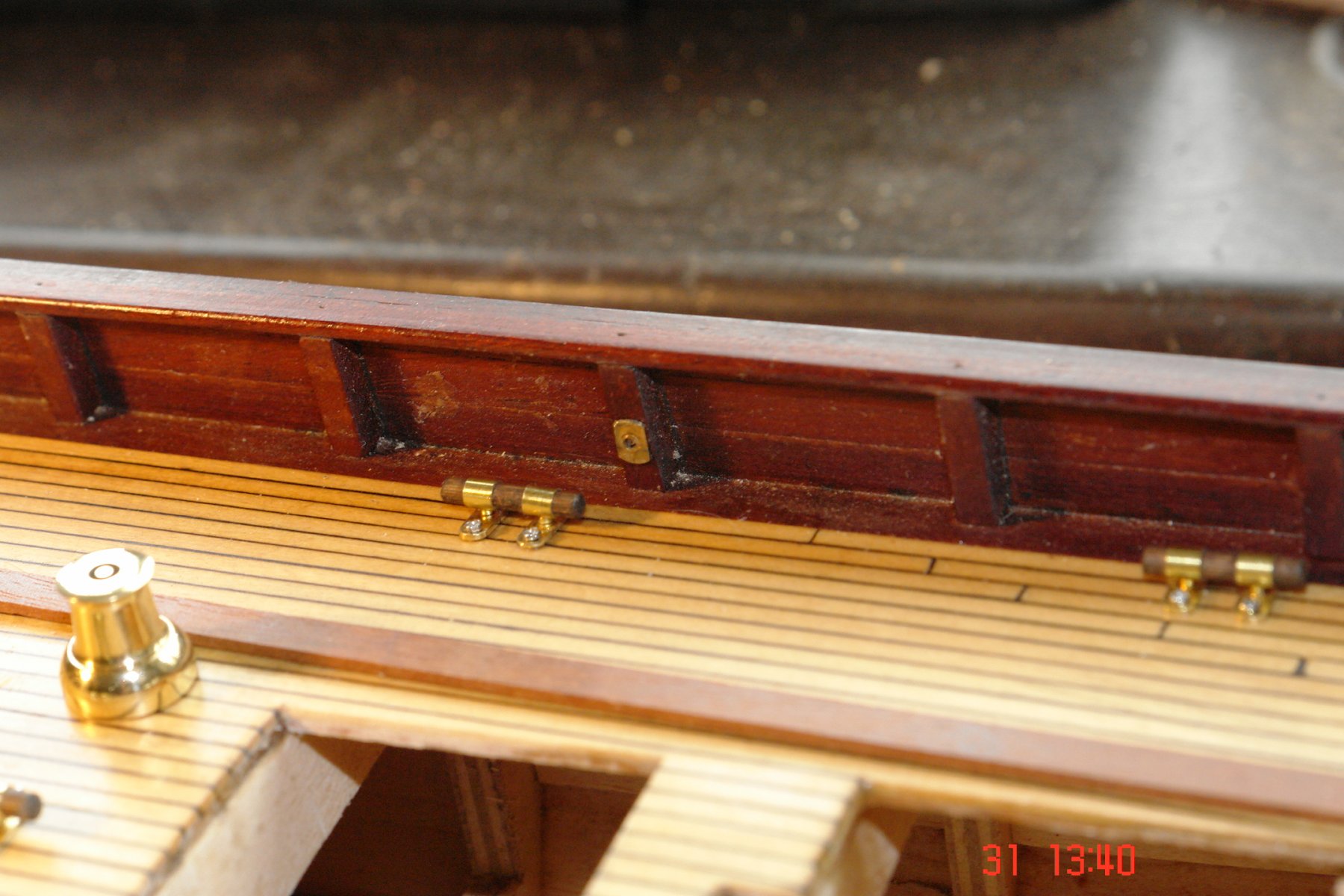
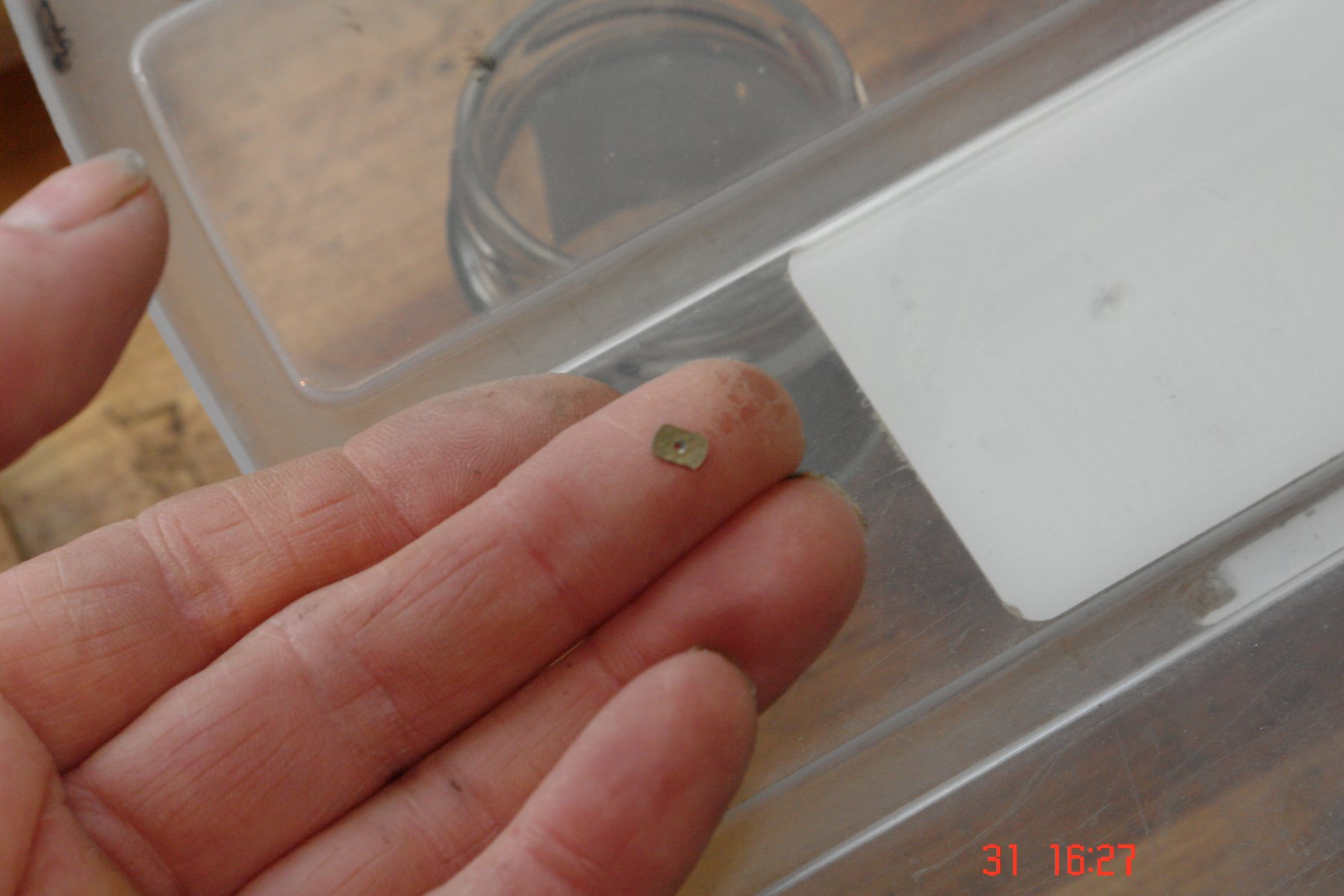
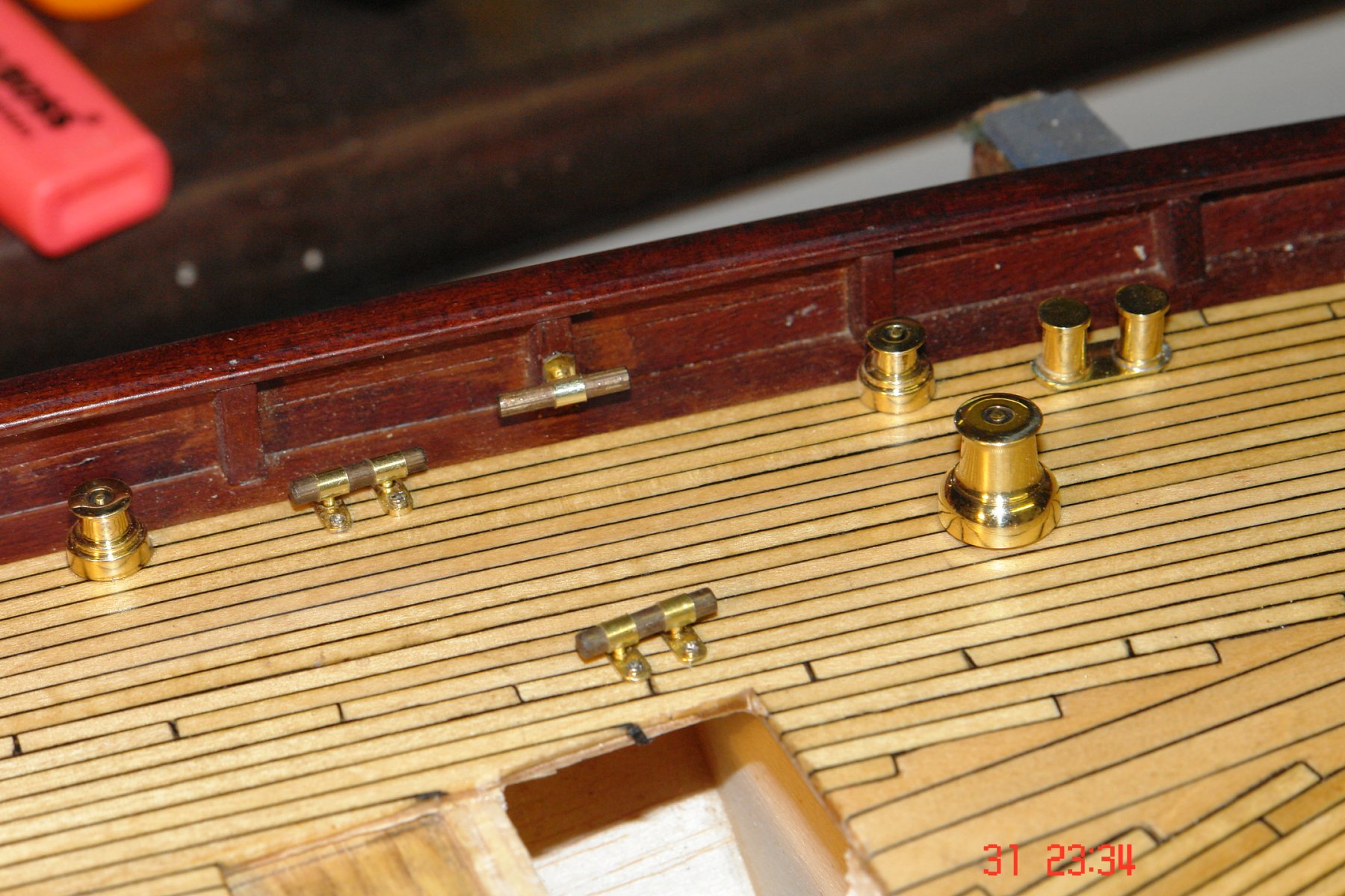
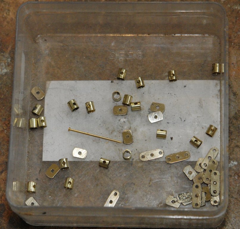
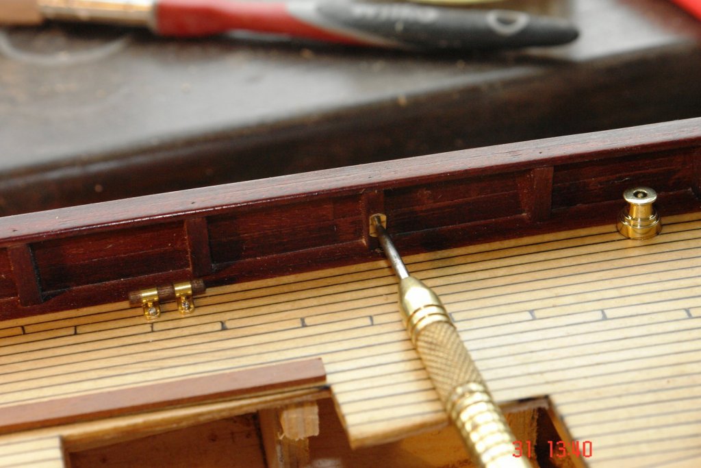
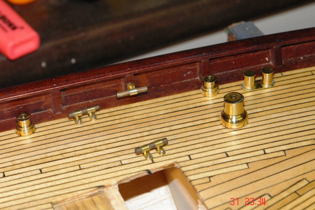
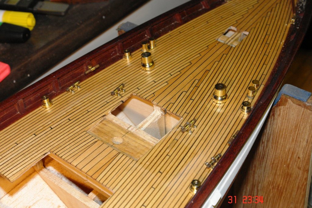
Arrrrrrrgh! Today was one of those "Damn and Blast" days. I was investigating the web to make sure that I got the positioning of the 4 secondary winches (omitted from the plans) in the correct position. One side effect of the investigation is that I found 4 cleats (2 deck mounted and 2 bulwark mounted) that were also omitted from the plans. I didn't have enough spare components so it was back to a production run. Also I had been mithering about the bulwark cleats being a tad too large and I hadn't really done a detailed job on the mounting plate. The need to set up the production line once more prompted me to rip off the existing bulwark cleats and replace them. The bulwark cleats have a single central mounting point with the foot being attached to the bulwark frames. The feet are quite small. The results of a full days production - the .750" pin is included for scale:- I glued the feet to the frames before passing the cleat mounting pin through the hole. I think I now have the right number cleats and winches on the rear deck - only time will tell!!


- 882 replies
-
- 12
-
-
That makes a lot of sense Michael. My mill is quite small in comparison to yours - a benefit much of the time but it can be quite tedious when I have to remove a lot of metal.
-
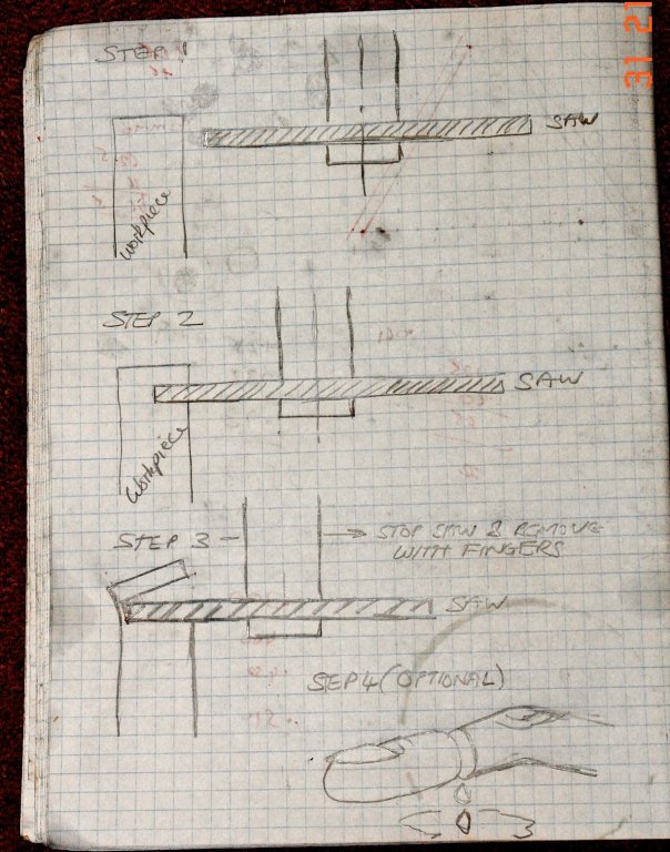
Greg, My lathe also has backlash - I have never worked on one that doesn't. All I do is make sure that the settings are always made when winding the dials in one direction - clockwise is normal. If I need to move the slide or saddle in the opposite direction I just wind the dial further than I need to go and then wind it back to the setting in the clockwise direction. This was the way I was taught to do it when I was an apprentice 50 years ago and it works well. The fitting of digital scales eliminates the problem and can be done quite cheaply these days. Bill, The best way to avoid the problem of cut off pieces flying across the workshop is as follows. 1. Advance the slitting saw into the component to make the cut. 2. As you come to the end of the cut slow down the rate of feed of the saw into the workpiece (best done using manual feed). 3. Just before the part comes away from the parent metal it will begin to rise away. This is because the web retaining it has insufficient strength to resist the pushing force of the saw. 4. At this point stop the saw, and use your fingers to pull the part free. If you are making lots of parts remember always to stop the saw - you would be surprised how tempting it can be to chance it. The sketch may help:-
-
Michael, More of a work of art than a production tool. Maybe you should put it in the lounge as objet d'art. Just one point I haven't quite worked out. I know you say you don't want to use the large mill but what is it about your mill that makes you want to go down this route rather than use it. Is it something to do with the "feel" during the drilling operation. You said somewhere that the mill has a DRO so presumably fine x,y,z coordinate control isn't a problem?
-
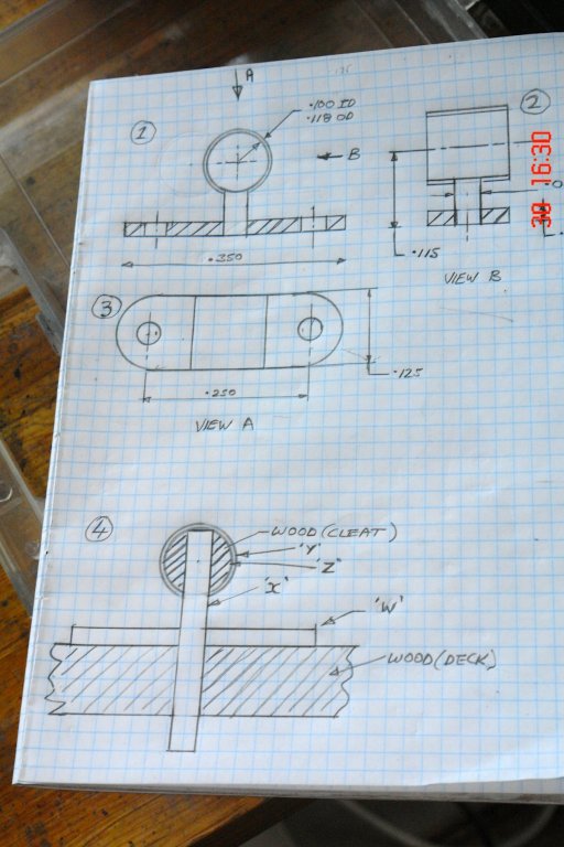
Richard, Michael, Bedford, Nils, John, Rob, Per. Thank you all for your very nice comments. Like most of us I build models for my own entertainment and pleasure, it is however very much appreciated when fellow shipwrights offer support and encouragement. Thanks to all of you all for taking the time and effort to comment. Now to deal with the questions:- Michael A picture may help (sorry I mixed 1st and 3rd angle projection). The top of the page (numbered 1,2 and 3) is what I set out to make. I did think about making a jig and then soldering the 3 parts together but I wasn't convinced it would be neat enough with the solder. Given the size and number of the parts I didn't fancy the clean up task. I realised that I could make it look right while achieving a robust construction by adopting the approach depicted in sketch 4. The sequence was as follows:- 1 Form the wooden cleat cross member (sketch 4z) and drill 2 cross holes in it .250" apart - these holes to take the pins (sketch 4x). I drilled the holes accurately on the mill using the DRO. 2 Make the collars (sketch 4y). These collars each have 1 cross hole pre drilled. 3 Slip two collars over each cross members and align the collar holes with the cross holes in the cleat. 4 Insert 2 pins (sketch 4y) into the holes in the cleat cross member and glue with CA. The contact area for the glue is large as the bond is between the pin and the wooden cross member. 5 Mount the feet (sketch 4w) on the deck and secure with 'spectacle screws" and CA glue. (I used a jig to accurately drill the 4 holes per cleat). 6 Drill through the deck at the location of the middle hole in each foot. 7 Apply glue to the pins of the cleat sub-assembly (step 4 above) 8 Insert the sub assembly into the holes in the feet / deck. The contact area for the glue is large as the bond is between the pin and the wooden deck. I used a spacer to make sure the distance from deck to cross member was consistent. It worked but was a bit complex. I'm sure others would find a simpler method. Per. I make them look the same by repeating the sequence and settings on the late for each item. For example the sequence went something like this. Set .375" bar in lathe. Face end. Centre drill. Drill .080" hole in end .100 deep (one turn of tailstock handle) Replace drill with .040" drill and push until it bottoms in hole. Drill .100 deep. Push tailstock away. Bring lathe tool into contact with the outside of the bar and set the cross slide dial to zero. Move lathe saddle away from work. Wind dial on the .025". (to reduce the diameter from .375 to .325) Move lathe tool until it touches the face of the bar and set saddle dial to zero. Take cut, moving the saddle until the cut diameter is .500" long. Etc, etc. The trick is to record the sequence and the dial settings for each step, much the same as you would do if you were programming a CNC lathe. It would be much easier if I had a CNC lathe but I am a miser. Richard. I agree with Michael. An unused lathe is like an unloved wife. They cease up and become useless.
-
Dan. this might be one option for constructing yor lattice. http://www.albionhobbies.com/connecto/. Although it might be a bit expensive.
- 287 replies
-
- 3
-
-
- michelangelo
- ocean liner
- (and 1 more)
-
John, Thank you. Once again damned by faint praise. Have you been taking lessons from my wife? The song was an old one when I used to sing it walking home from school and that was 50 years ago. So I guess inflation has taken its toll.