KeithAug
-
Posts
3,986 -
Joined
-
Last visited
Content Type
Profiles
Forums
Gallery
Events
Everything posted by KeithAug
-
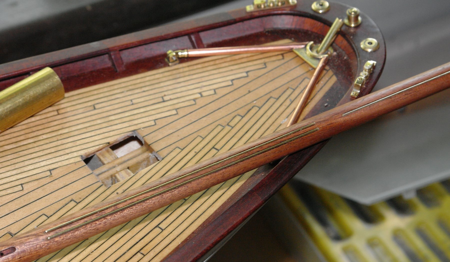
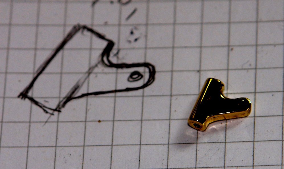
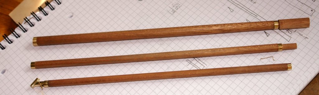
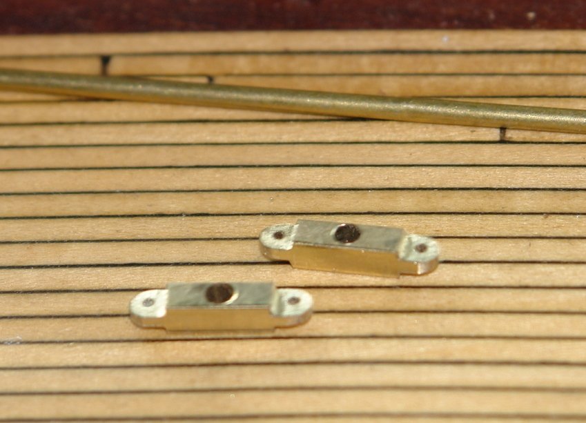
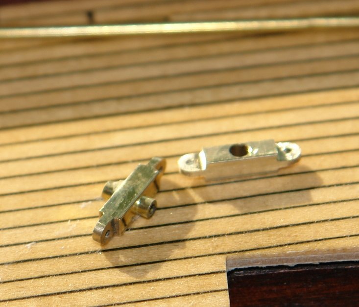
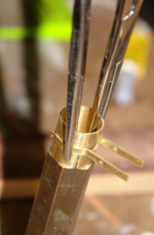
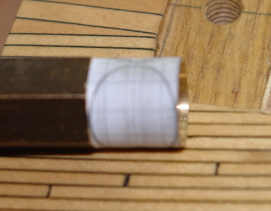
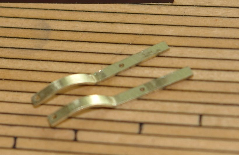
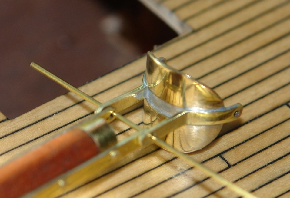
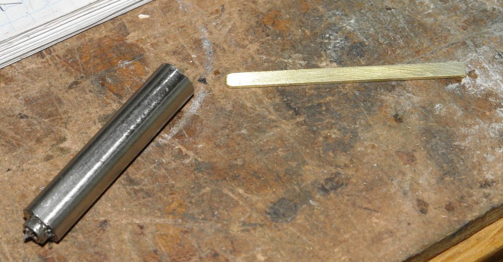
 I seem to be in rather a repetitive phase of the build. Having completed the main boom and gaff I started on 3 similar elements, the foresail boom and gaff and the staysail boom. All were turned from mahogany dowel. The only fairly unique part was the attachment for the staysail boom. This is a bracket that sits at the base on the foremast stay. I decided to cut this out of flat brass bar - initially a bit of milling followed by shaping with a piercing saw, hand filing and machine polishing. The bracket is just under 0.3" long. The mating bracket on the boom was turned on the lathe and slotted on the mill. The foresail boom and gaff end fittings are at a very early stage of production. The wire holding the bracket in place is a "wondering part controller". My helper is starting to develop very bad habits. I settle her down in the lounge and sneak off to the workshop. After about 15 minutes she notices I am missing and comes with her ball to retrieve me. I am then forced into 10 minutes ball throwing before I escape once again. This has happened 4 times today and it is very disruptive.

-
Martin Nice work. I know earlier you rejected the idea of artificially deepening the keel to improve the sailing characteristics. Like you I like the hull to be true to scale and I hope your decision proves workable. The other area of departure from scale that is usually built in to scale sailing models is in the size of the rudder, working models having much broader rudders. This is a compromise easily made as the sailing and display rudders can be made to interchange. You may get away with it but if you design in interchangeability it could be a worthy investment.
-
Dan, Thank you. Its easier when you are working at larger scales. I am equally impressed by builders like yourself that manage to create detail at much smaller scales.
-
Tom, Thank you for taking the time to look at my log. The topping lift on Altair runs from the base of the mast to the head of the lower mast and then down to a position 2/3 way along the boom. I don't believe that the slack line below the boom is the topping lift. JD. I did 30 weeks of machine training at the start of my engineering apprenticeship in 1969. We got a good grounding in turning, milling, grinding, casting, fitting, sheet metal work and metal forming. I then didn't use the skills seriously until I retired in 2012 when I bought a small Lathe and mill. Fortunately I had remembered the basics from 43 years before. So no I am not a jeweller but thank you for the compliment.
-
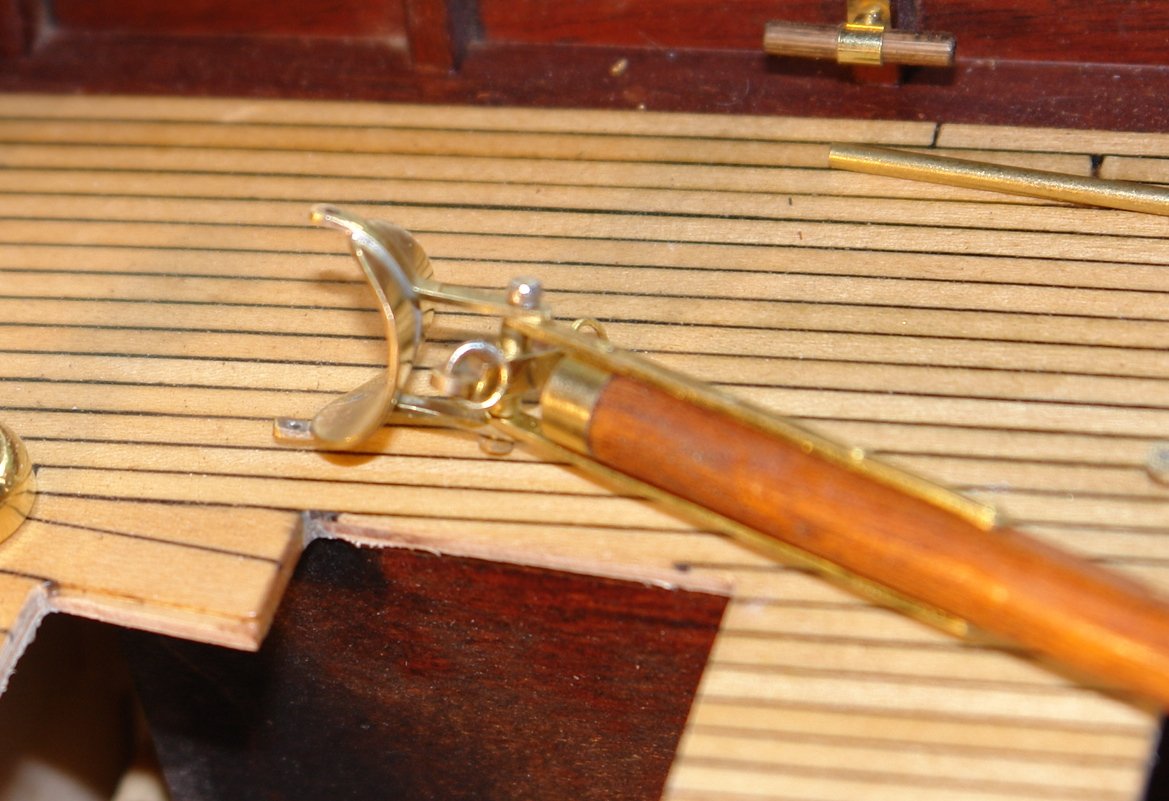
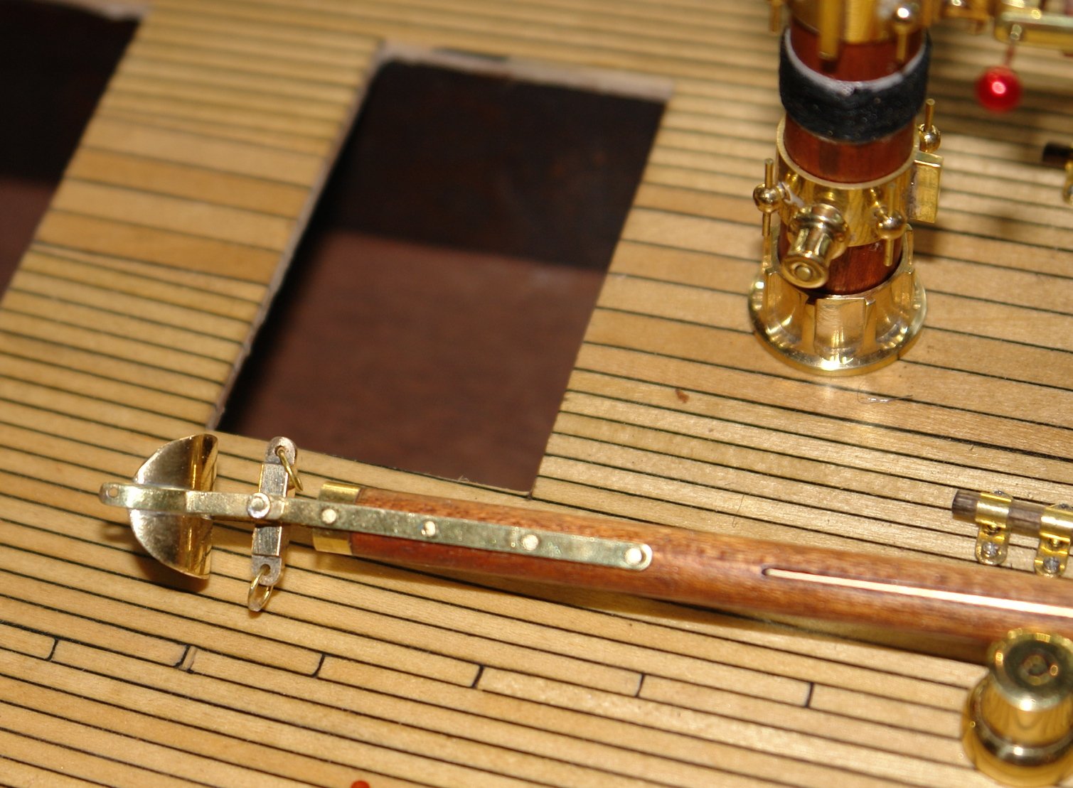
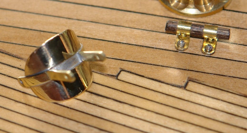
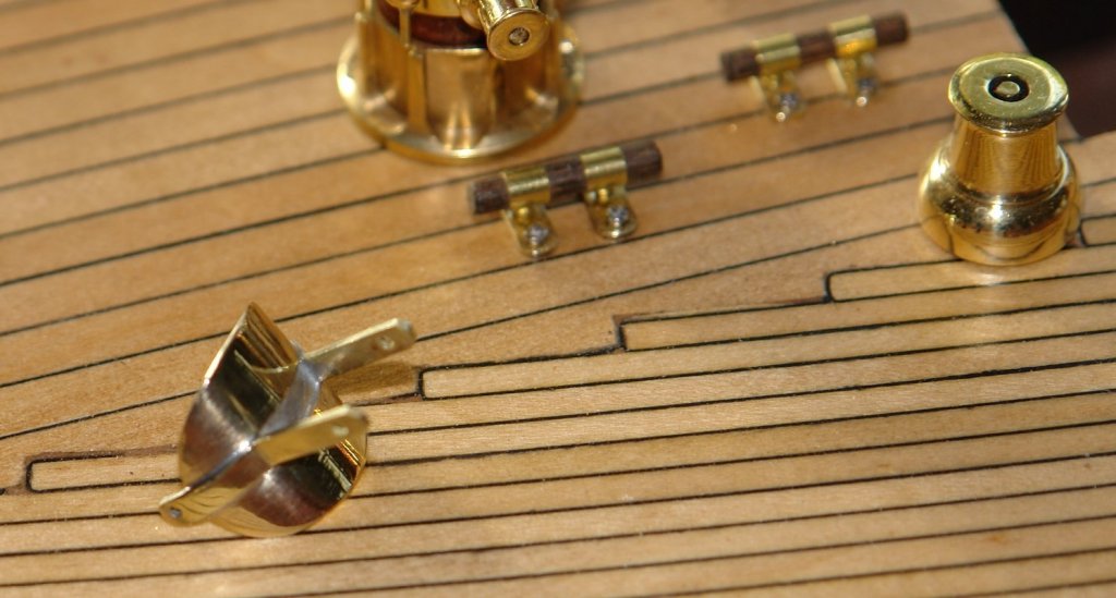
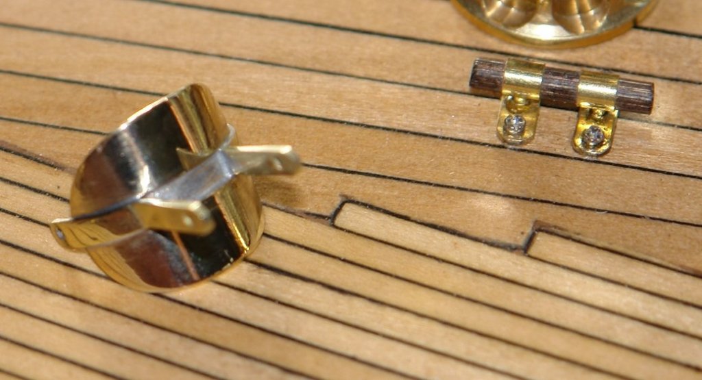
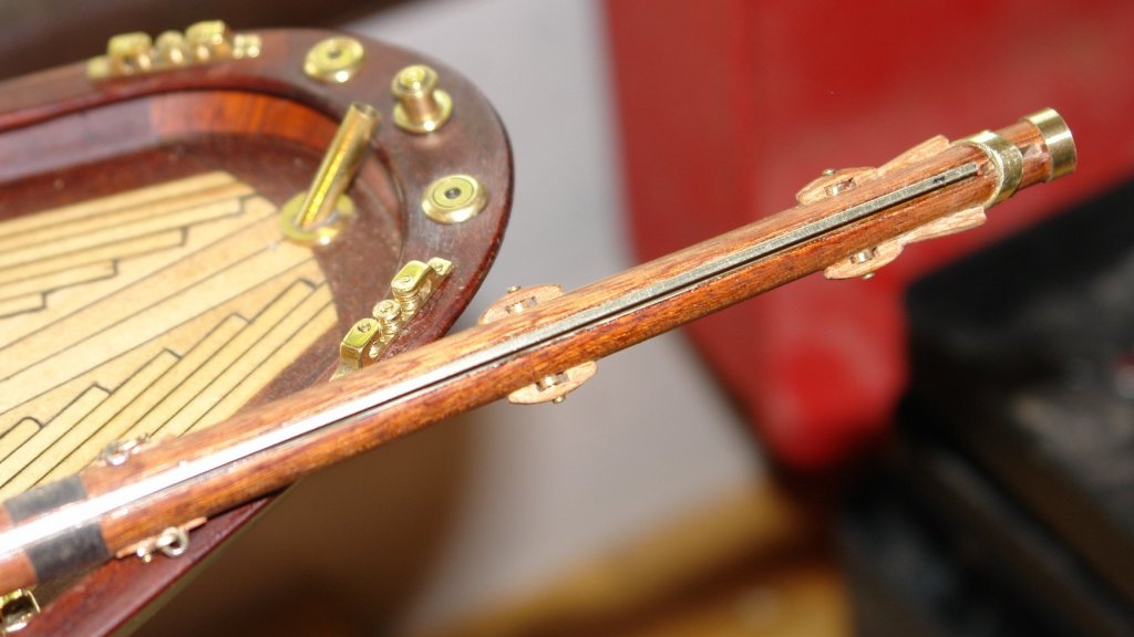
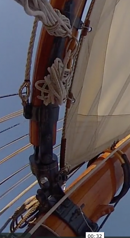
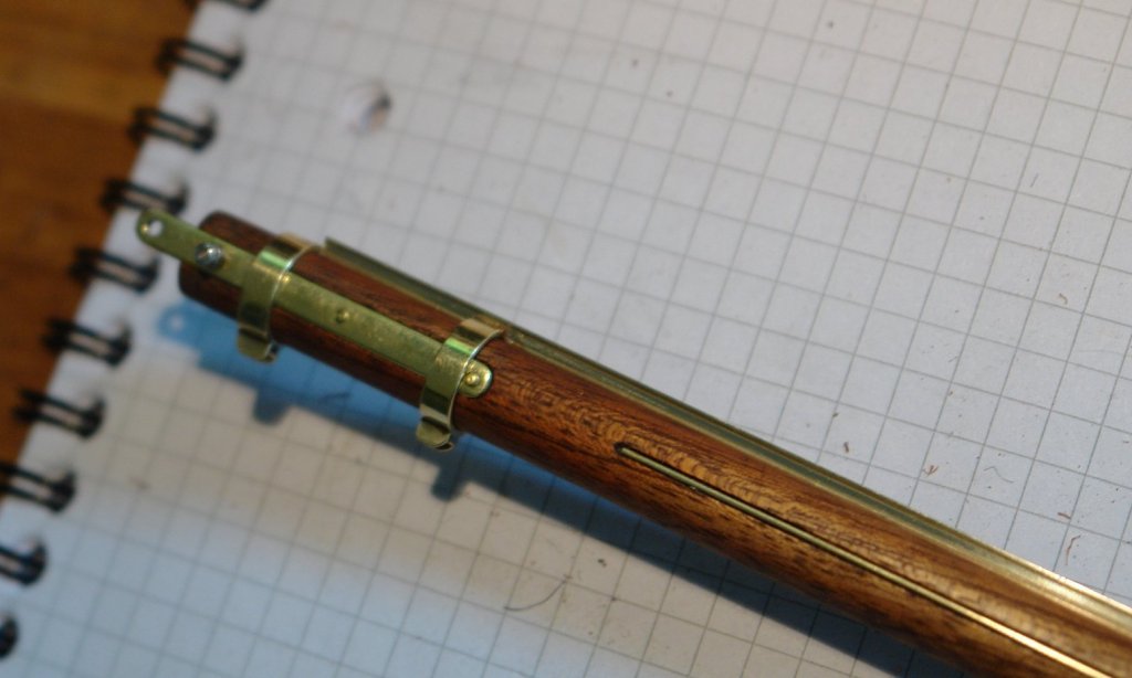
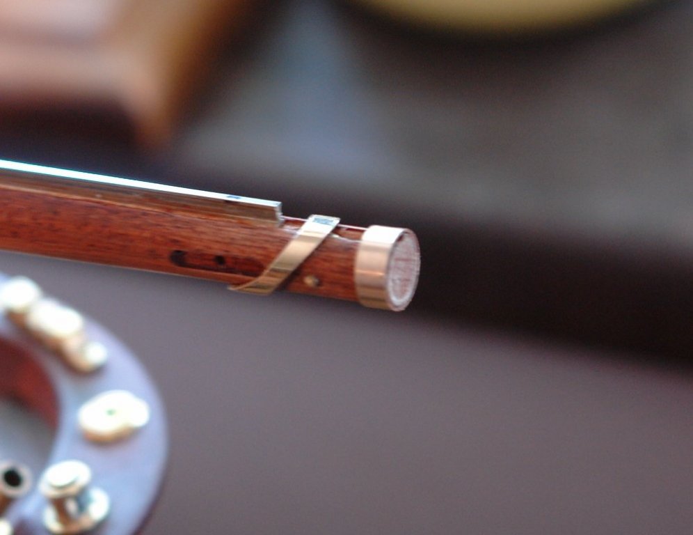
I finished the gaff so I thought I would post the photos to get the log up to date. Stirrup - for attaching the gaff lift. Assembled -


-
Nils, reference "no models in the living area of the house" have you you thought about convincing your other half of the benefits of reducing the occupied areas. 1 less cleaning 2 less heating 3 less space to attract unwanted visitors If you start the brainwashing now in a decade or so she will believe it was her idea all the time. As my wife ocassionally looks at my posts I will have to delete this thread in case she gets ideas about display location bans.
- 2,625 replies
-
- 5
-

-
- kaiser wilhelm der grosse
- passenger steamer
- (and 1 more)
-
ancre La Salamandre by tadheus - 1:24
KeithAug replied to tadheus's topic in - Build logs for subjects built 1751 - 1800
Hi Pawel Have you tried modelling the fire for an added touch of realism?????????????????????????????????? just teasing. Nice work as always. -
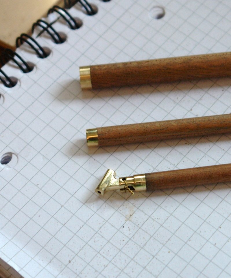
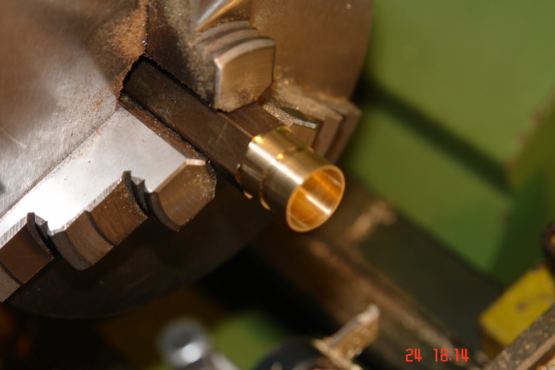
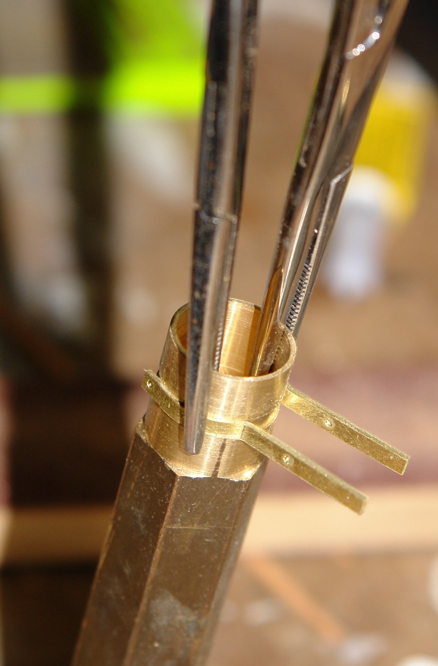
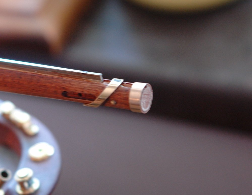
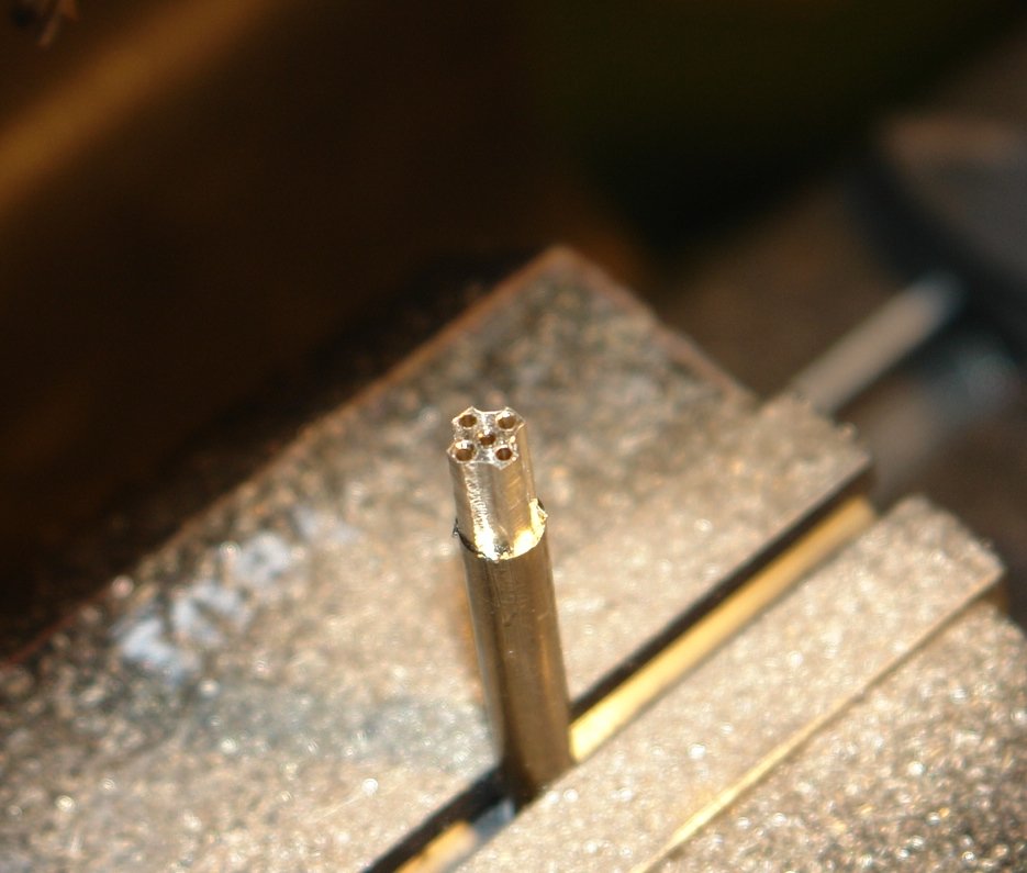
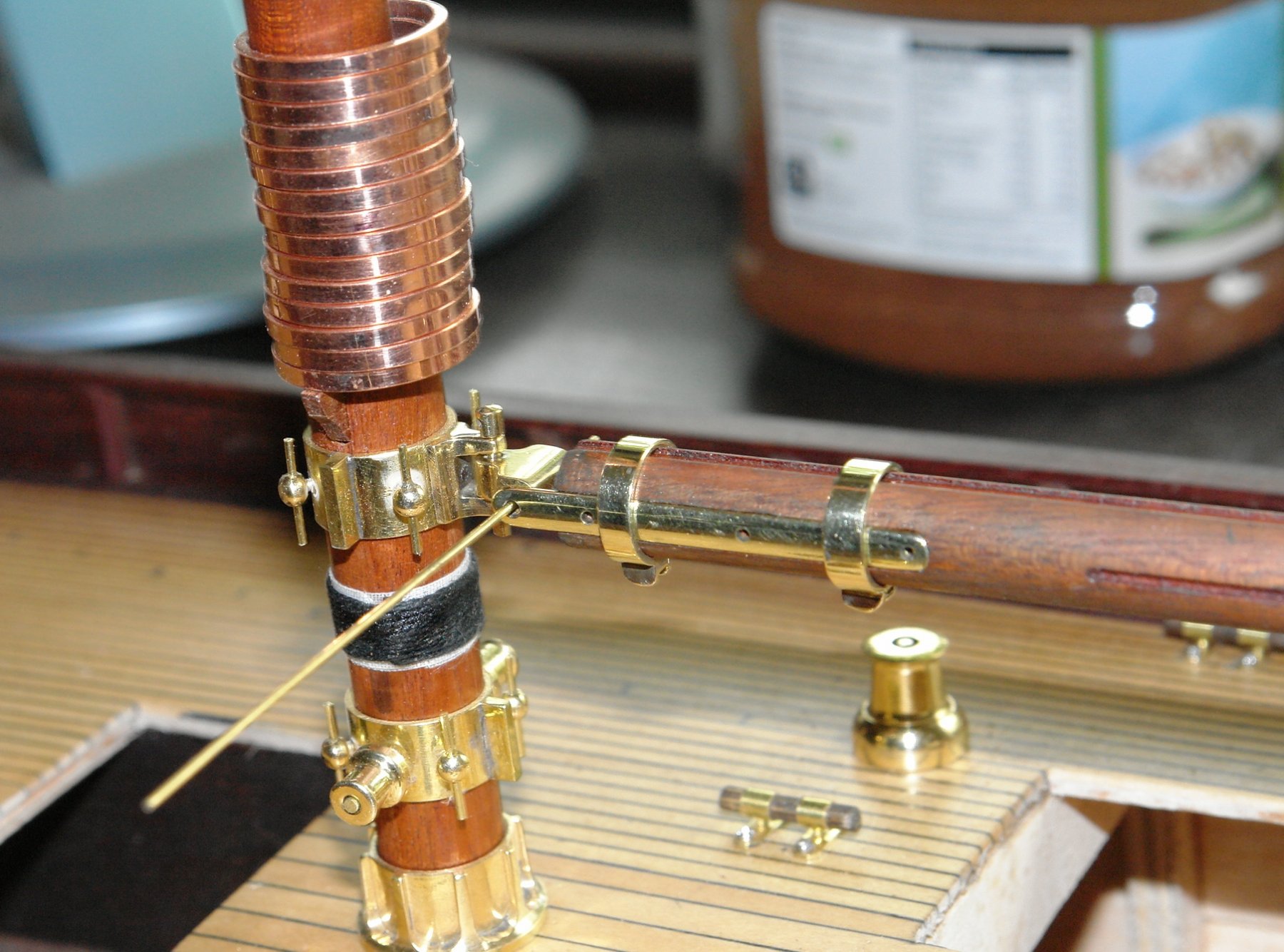
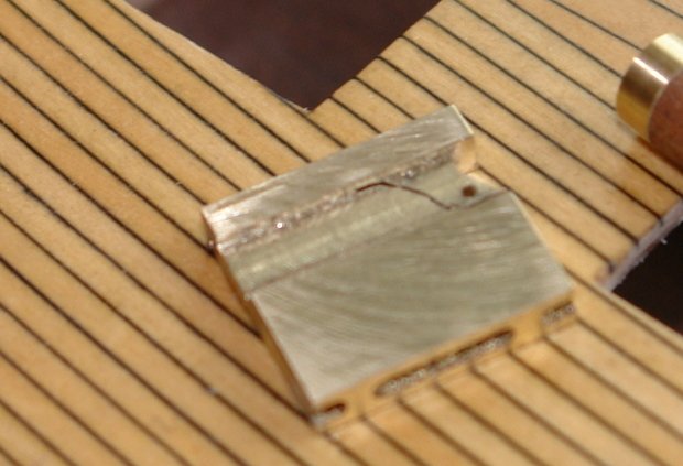
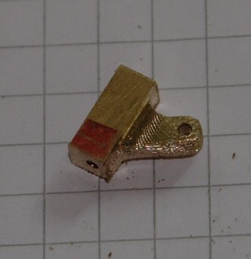
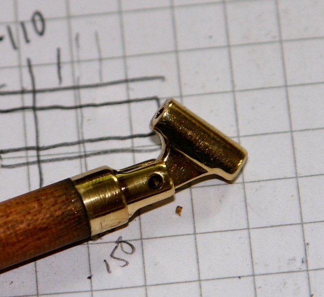
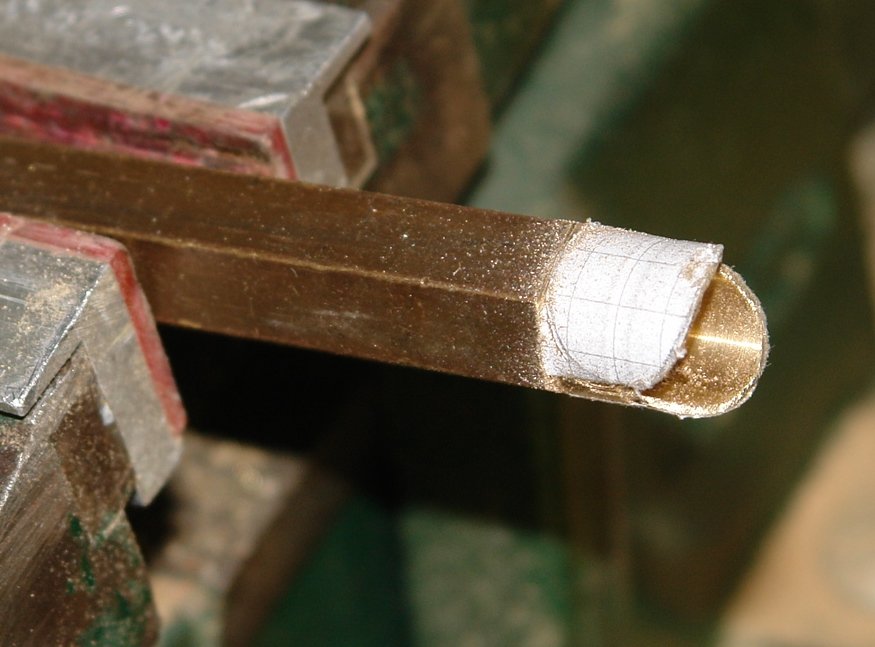
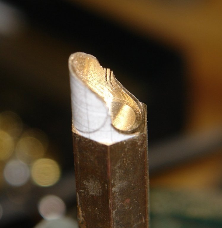
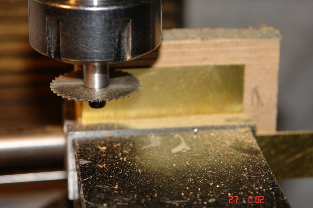
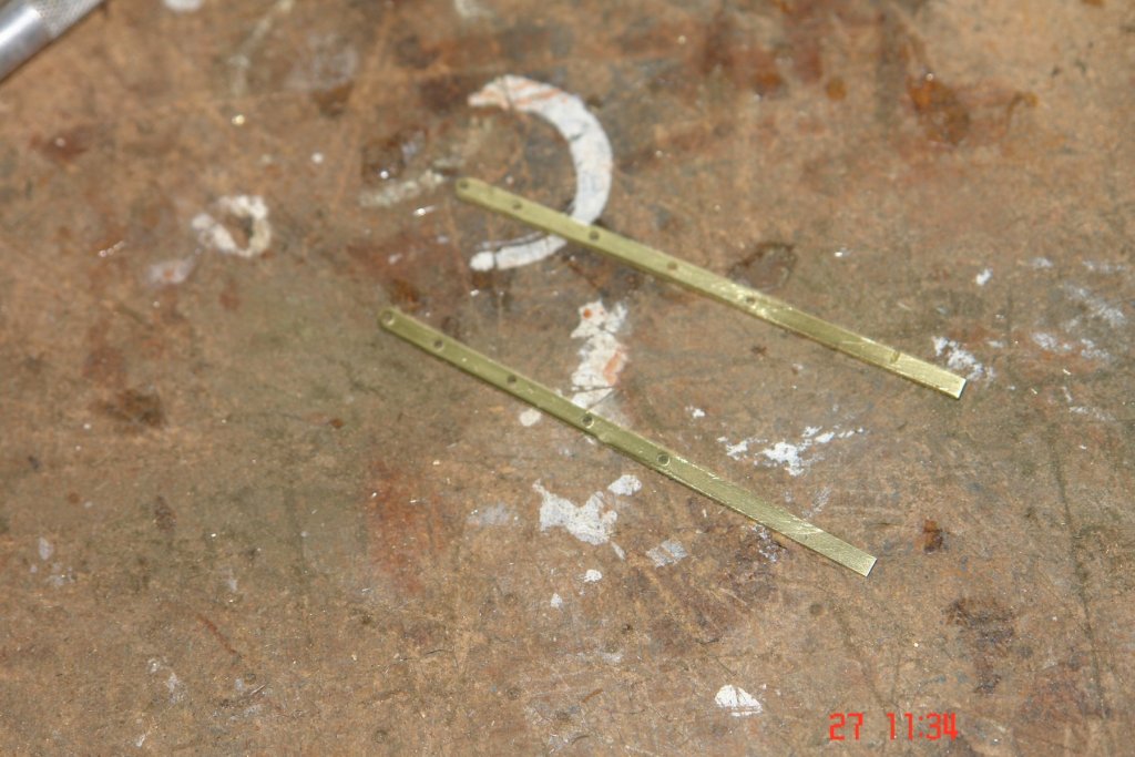
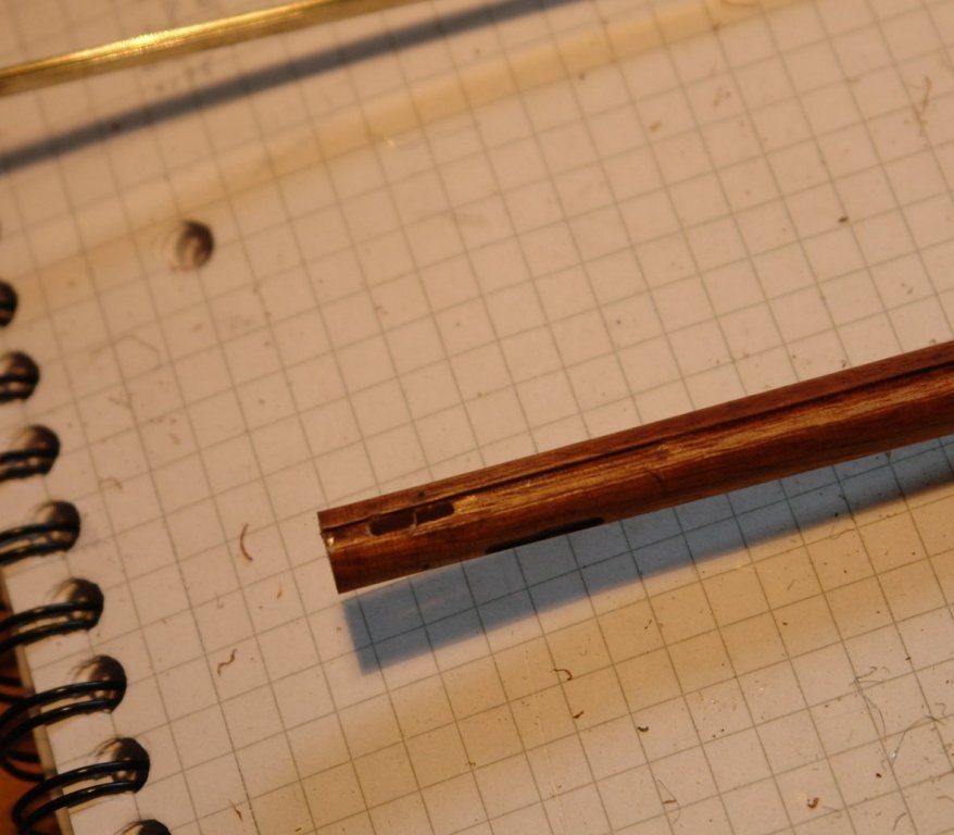
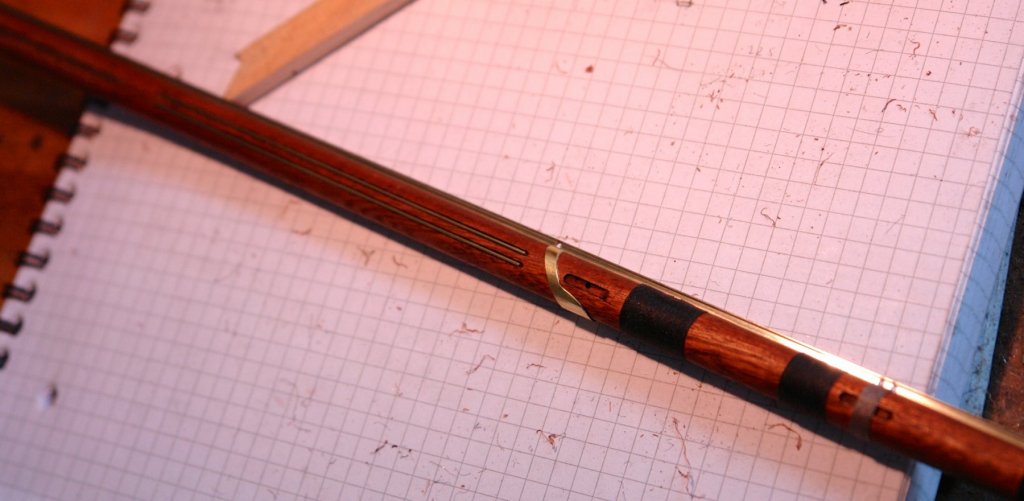
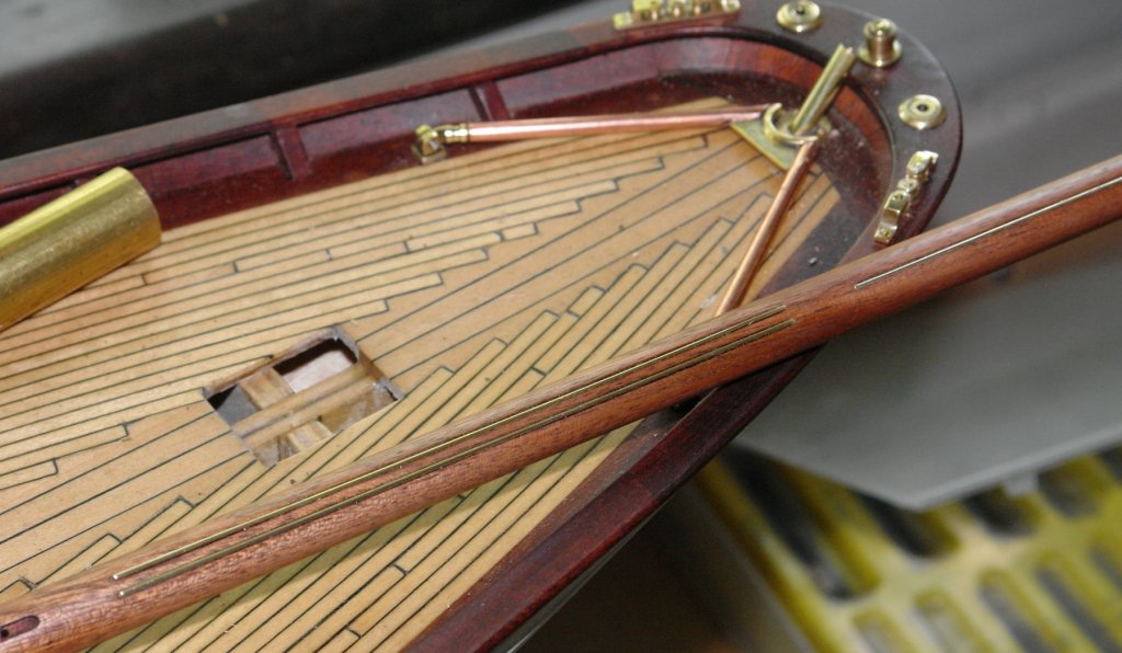
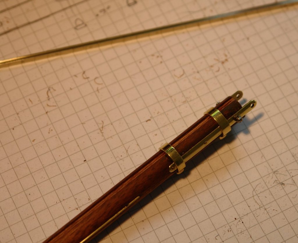
Thank you Richard - I was allowed extra shed time as a present. So to continue todays work. I needed to make the gaff saddle. A slightly tricky little number. The body was made from solid bar - very wasteful, tube would have been better but I just didn't have the right size. Tin bashing was also an option but it is one of my least favoured skills. I remember in the apprenticeship school being let loose on fabricating a funnel. Mine seemed to be a bit of a mess. So bar it was - bored and turned on the lath and slotted .001" wide at its waist to take attachment of the straps. The bore is about 5/8". I drilled the straps, bent them to shape and did a test fit. Straps .100" wide by .03" thick. The holes turned out to be in the wrong place so I threw them in the bin and made another pair - it just seemed to be one of those days. I drew two oval templates to make 2 bodies and stuck them to the pre turned bar using double sided tape. The shape was then roughly cut out with a piercing saw and finished with a file and wet and dry paper. The remade straps were then soldered in place while being held by forceps. The forceps were removed early (before adequately cool) and it all fell apart. Messy clean up of the components and try again. At least I'm on the way to making the second one.

-
Nils I had great fun mentally wondering around the deck. Thanks for posting these shots. Do you have plans of how and where you are going to display her?
- 2,625 replies
-
- 7
-
-
- kaiser wilhelm der grosse
- passenger steamer
- (and 1 more)
-
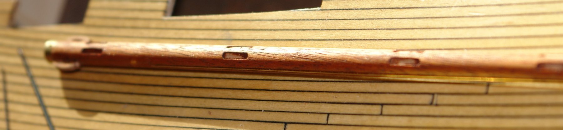
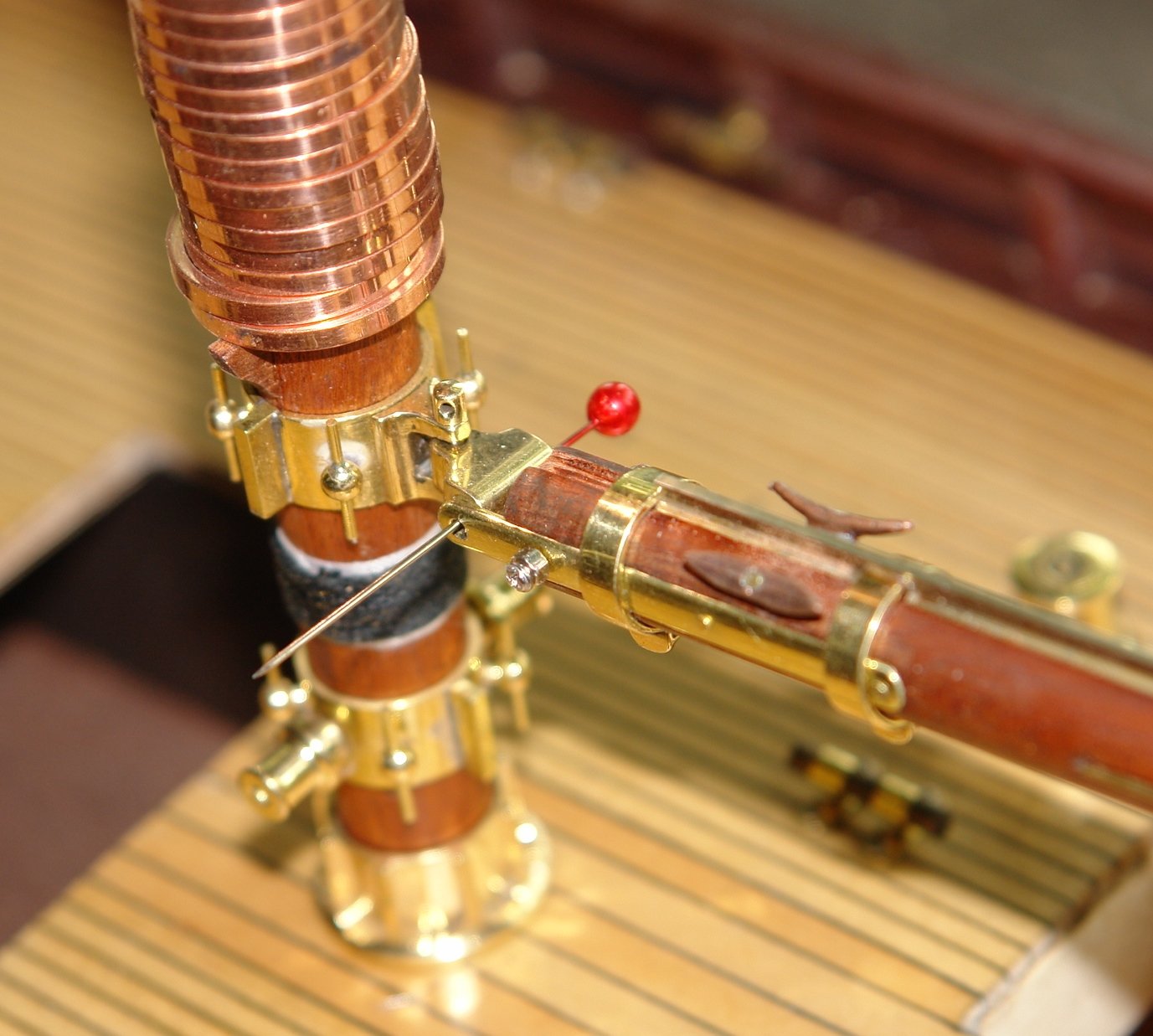
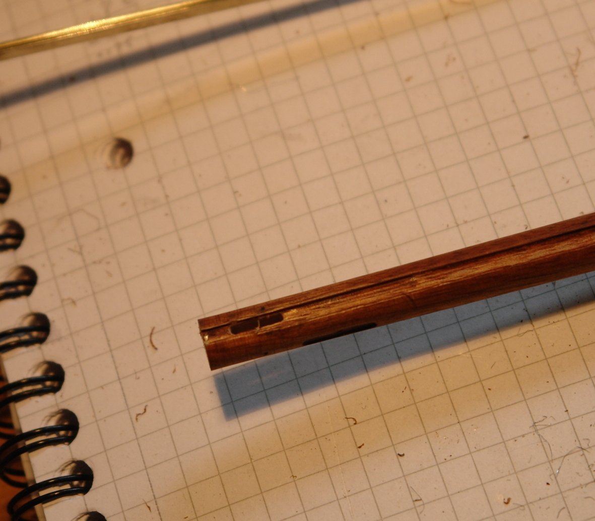
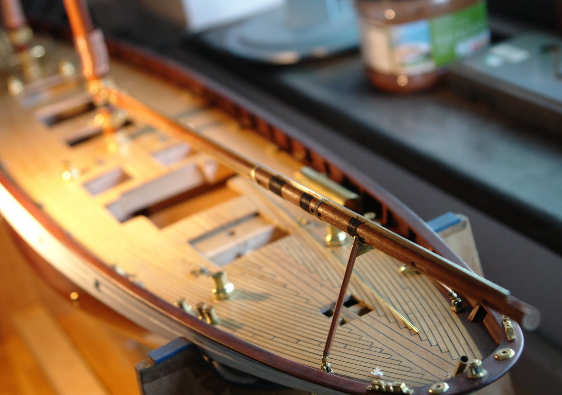
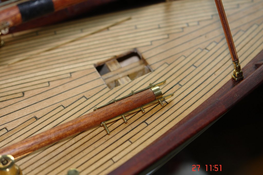
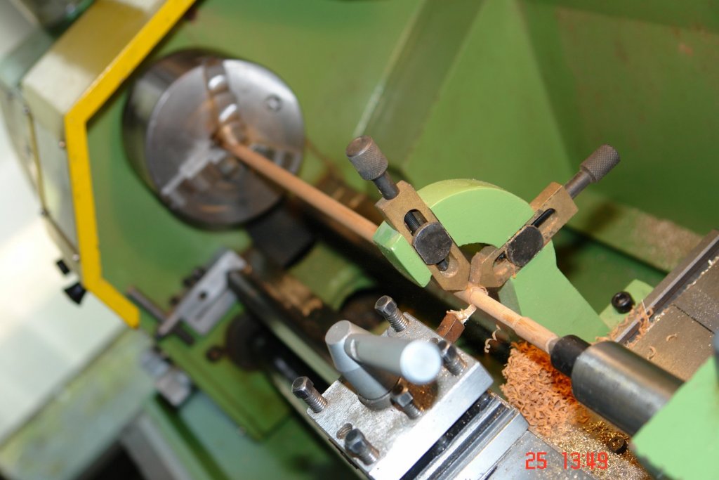
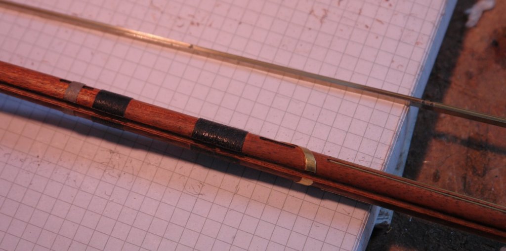
Progress on the main gaff has been fairly rapid (for me). Once again the boom was machined on the mill. 0.040" wide longitudinal slots were machined to take the rubbing strips and various other pockets were cut to take surface mounted pulleys and strop restraints. The fittings were then mounted - predominantly glued with CA. \ I needed .100" x .030" strips of brass from which to make the straps for the throat. These were slit from sheet on the mill to ensure accuracy. ...and once made they were drilled with .040" holes to take rivets. I made myself an anvil and used the brass wire to form rivets. No glue required. The boom is now complete awaiting the manufacture of the gaff saddle. Post script - Durrrr --- I have forgotten the sheaves!!!!!!


-
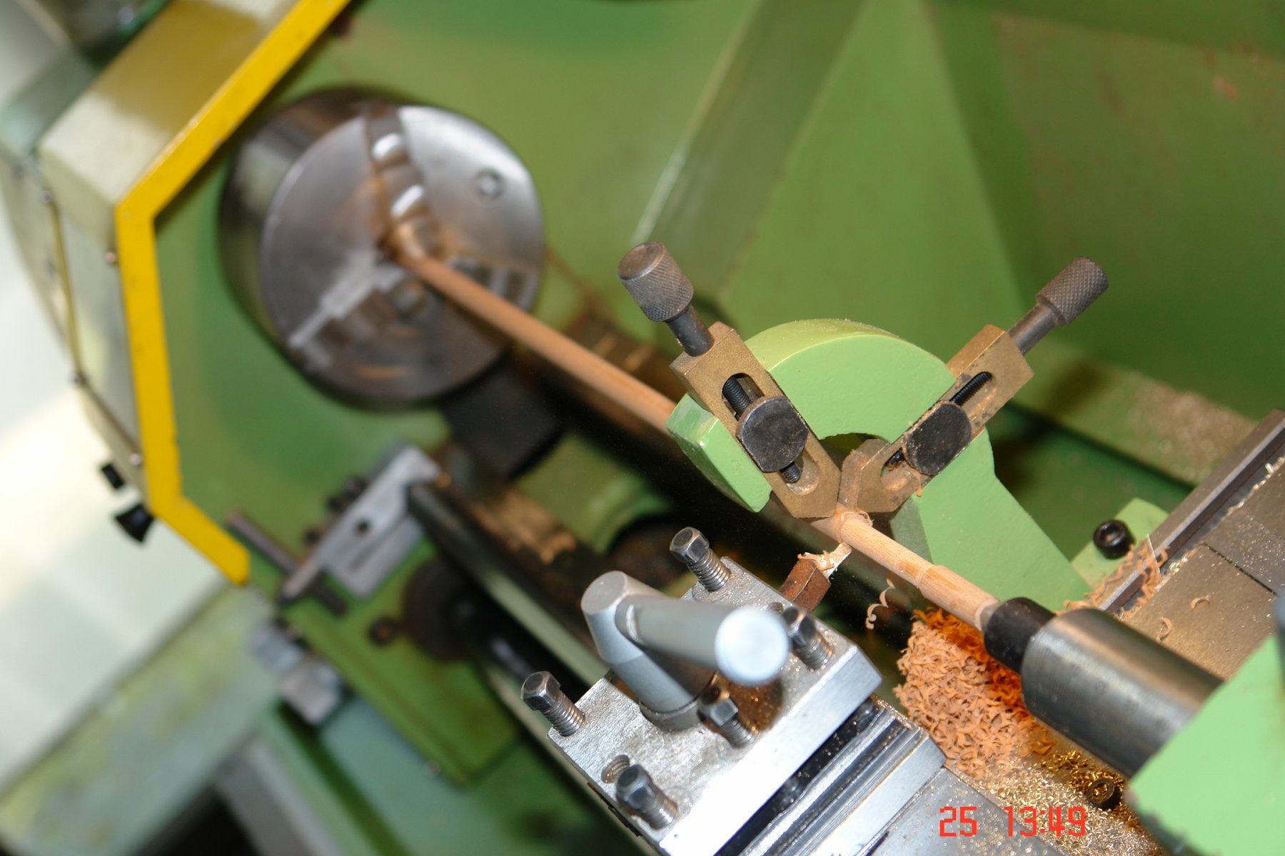
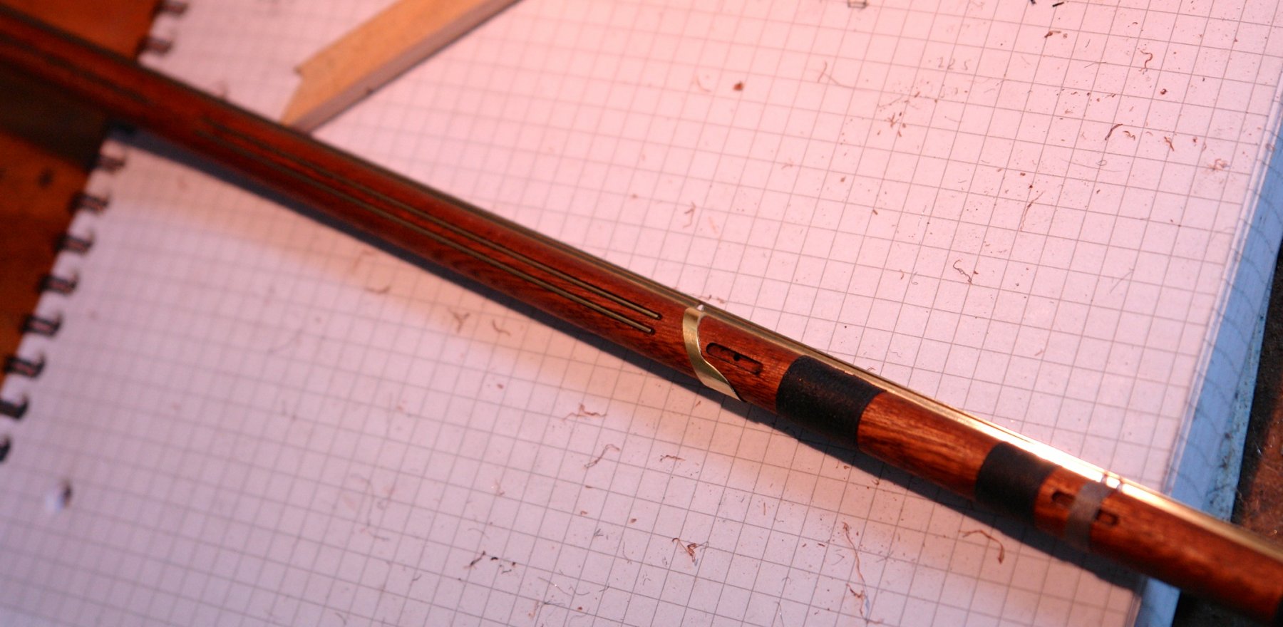
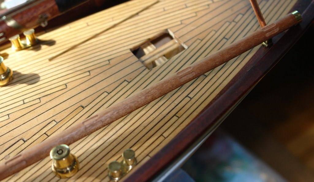
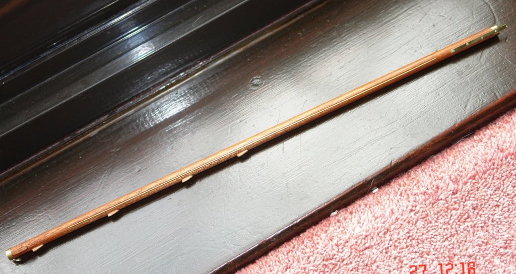
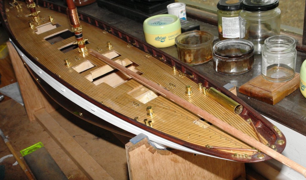
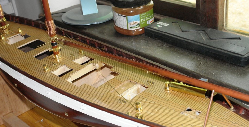
So finally the main boom is complete and awaiting rigging. I had missed the final pair of "side" pulleys so added them and I also put the sheaves in place (.100" diameter x .035" wide). I cheated a bit with the boom cleats as I had some of the correct size left from a previous build. They were however too bulky on the base so I cut them down and attached a central mounting pin. I then made a start on the main gaff. It is .275" diameter and I needed to turn down the dowel to size before cutting to length and adding the end reinforcing rings.


-
Jon Thanks. I had sort of got to the point of thinking the outhaul was removable. I'm sailing into the Hamble in a month or so's time so will call in to Fairlie if time permits.
-
Very nice Martin. I see you are adverse to throwing knife blades away. That one looks like it seen the sharpening stone more than a few times. Do you have a reference / link for your screw mark tool?
-
Richard Mr Fife seems to have been a bit of innovator with his mast and rigging designs. Eileen is just different enough to add to the confusion.

-
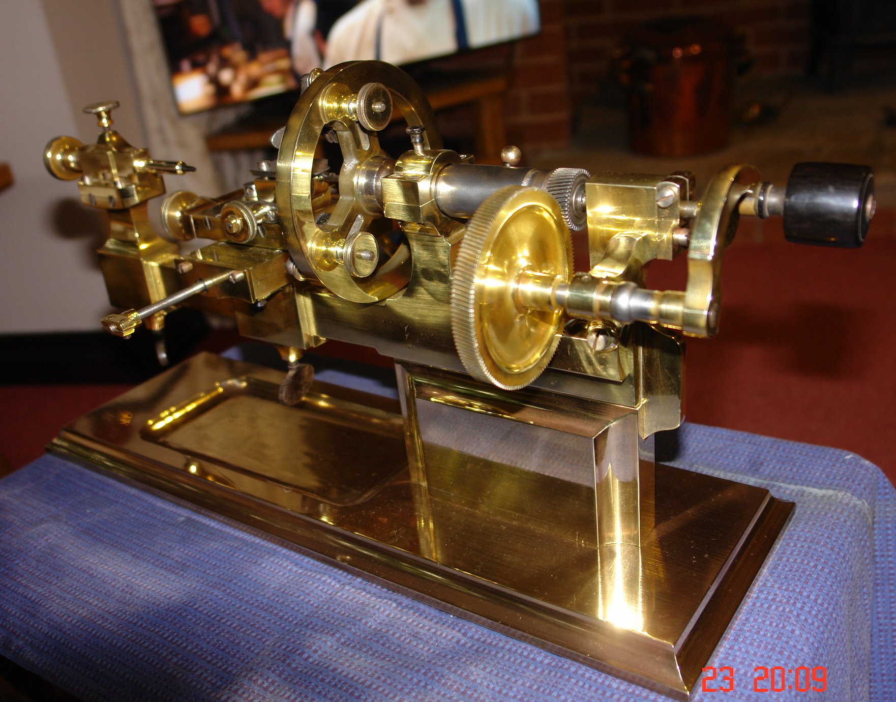
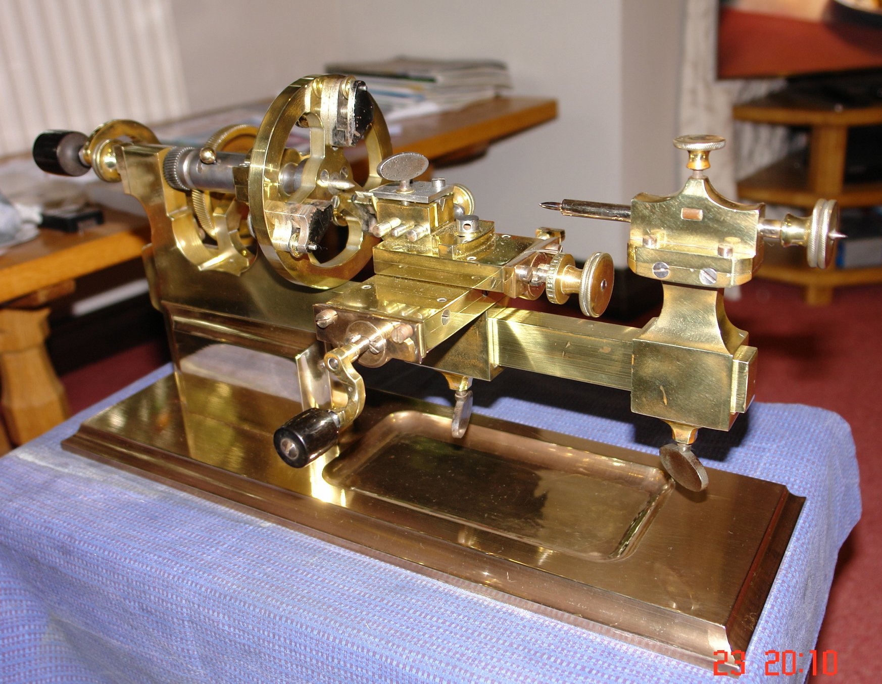
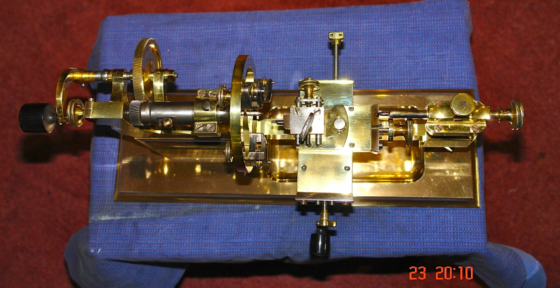
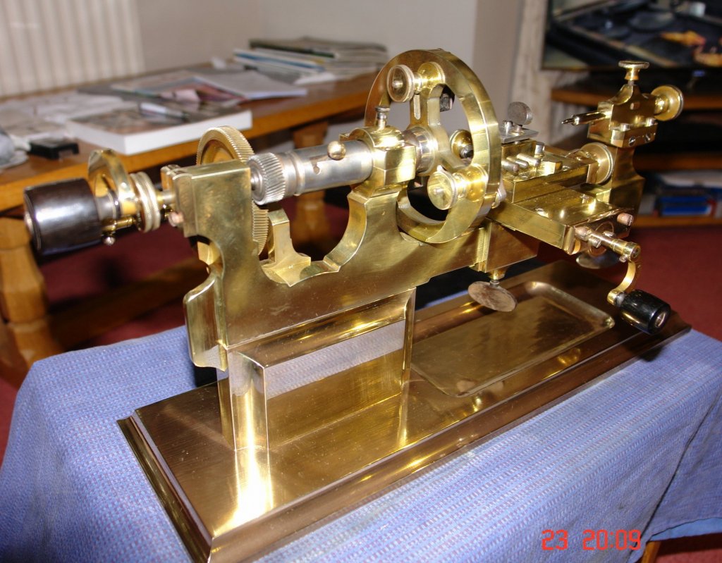
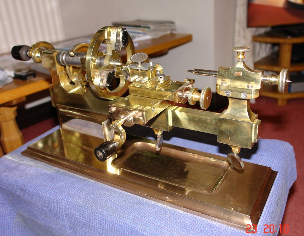
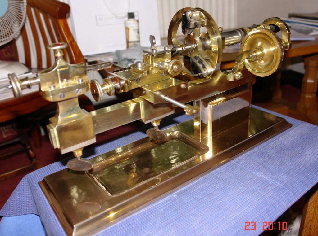
Michael, No, the large and small helical gears are fixed, as is the face plate. The larger gear is however mounted on a bracket and bolted to the main frame to make it easily removable. This is a design feature to allow the lathe to be quickly converted to belt drive. I have never seen one of this pattern that is as nice as this one. The baseplate and pedestal are typically made from wood or at best a rough piece of iron. This one is machined from bronze and the whole thing weighs 18kg. It has very few signs of damage or wear and is still silky smooth after a century and half. My guess is that it was never used in anger and was a demonstration model or something of that sort. it has however one flaw. The hand turning rest and mounting bracket is missing. I have spent a long time looking but as yet have not found one. It's on my to do list to make one but at the moment is some way from the top.
-
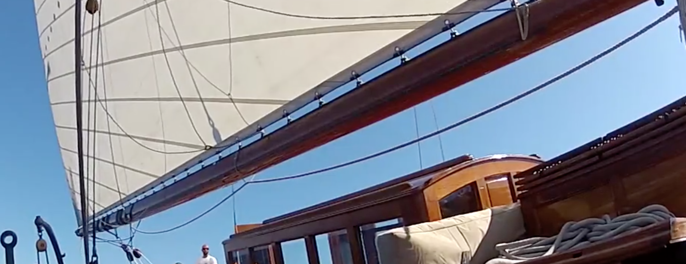
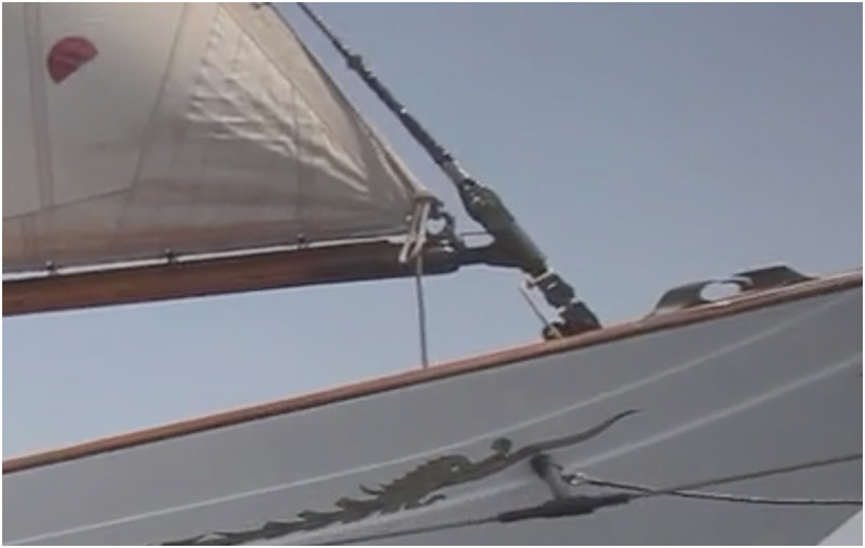
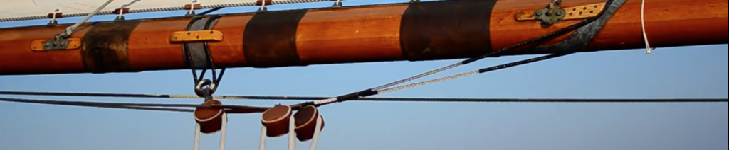
Richard and Herask - thank you. Also thank you to all who have liked my recent posts. Michael, I hadn't thought of the cleat option - I may look into that. Jon. thank you for your detailed and considered reply which I read with some interest. It felt right but then spurred me on to dig further. You may have further thoughts on my ongoing investigations:- These are different but quite poor views of the end of the main boom. The mainsail seems to be lashed to the 2 fixed eyes and i can't see any sign of an outhaul. I'm wondering if the sail is fixed and does not have an outhaul. It may just be re-tensioned occasionally when not under sail. In the photos below the line below the boom is quite slack even though the sail is full. It the line were a conventional outhaul the line would be tight???? In this shot looking up at the mast end of the boom the "assumed" outhaul line does not exist - but yet again the sail is full. Also I thought i would add the following to feed someones tool envy:-


-
Martin Venetian blind slats seem a little expensive at 50p. I found mine in a bin. They do however make nice deck planks as per attached photo. You should do well given all your model making experience.

-
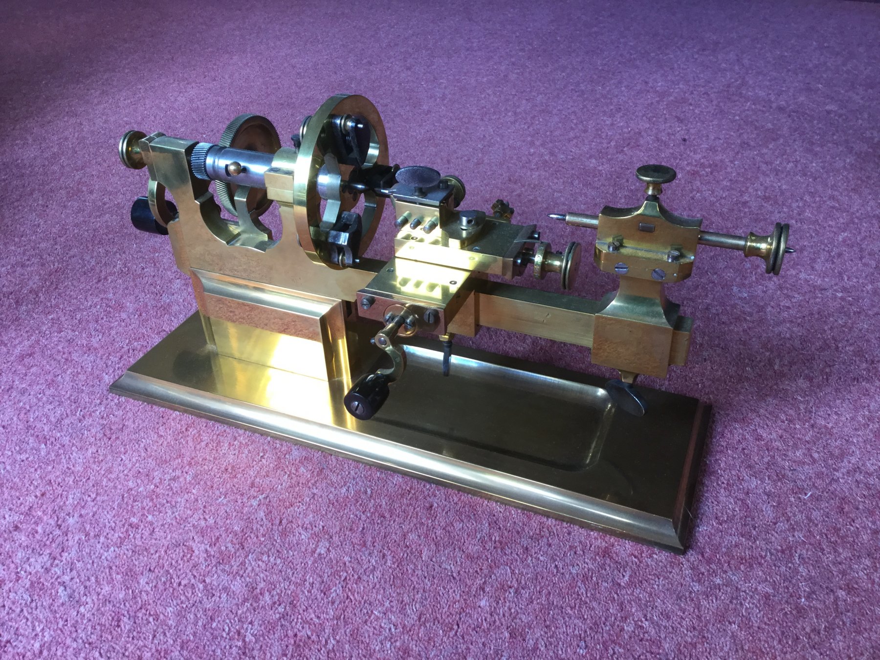
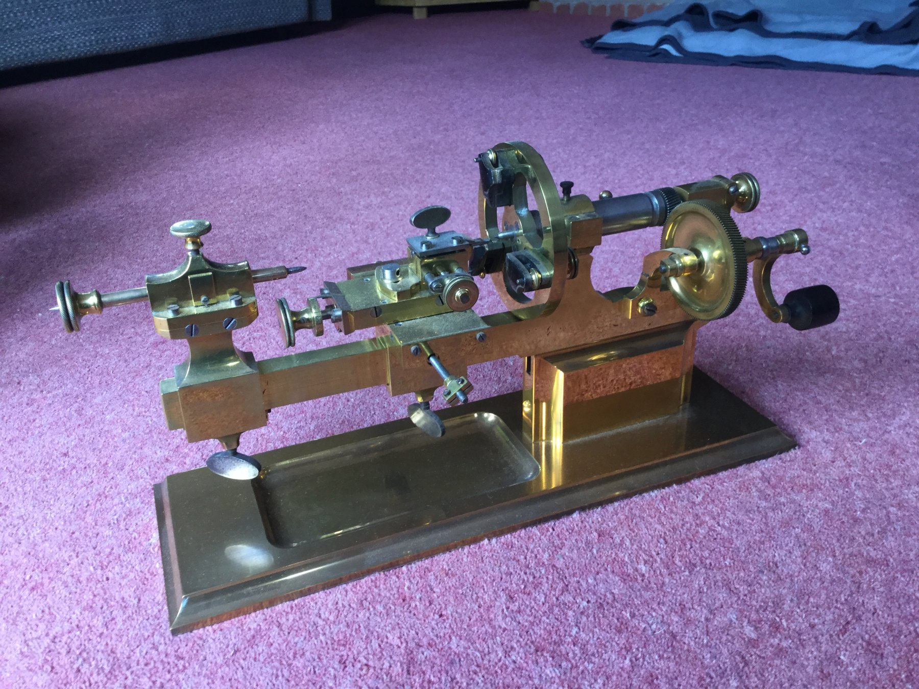
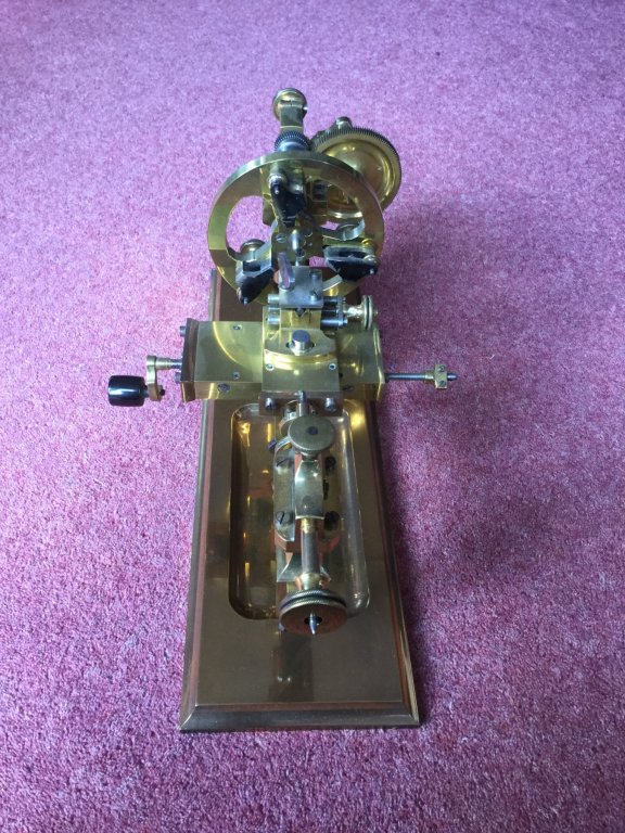
Hello Martin Your lathe dates from about 1850. I also have one. They were primarily used for making the various mounting plates that sit within the watch. You can see more detail here. http://www.lathes.co.uk/swissuniversal/ lovely model by the way.


- 94 replies
-
- 12
-
-
All looking very realistic Nils. Great job.
- 2,625 replies
-
- 4
-
-
- kaiser wilhelm der grosse
- passenger steamer
- (and 1 more)
-
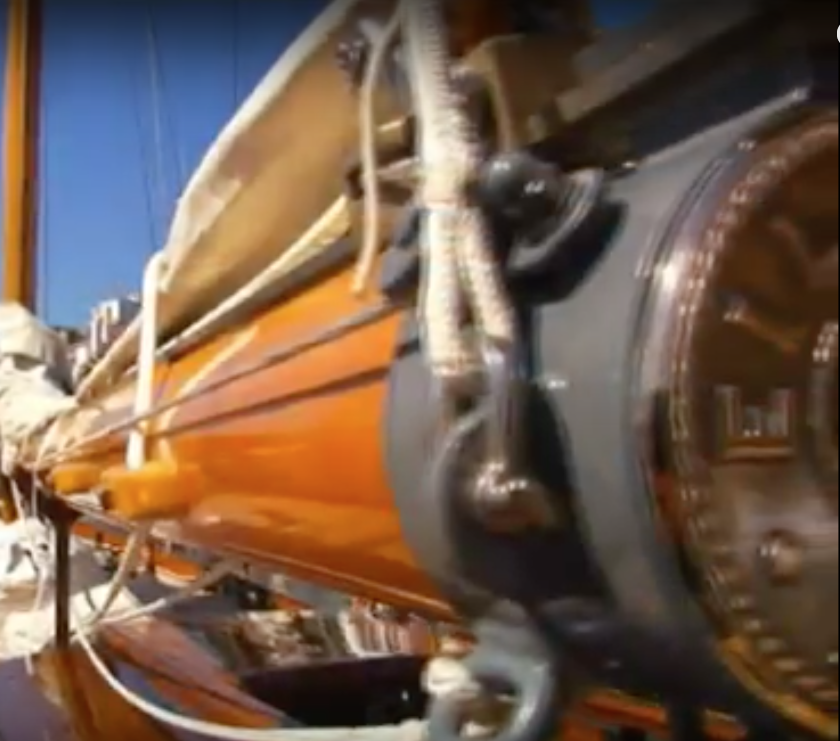
I have had another think,,,,,,,,,,,,,,,,,,,, The line on to the pulley and the winch is a reefing line. You can see it going on to the final pulley on the side of the boom in the last image. Much head scratching!!!!!!!!!!!
-
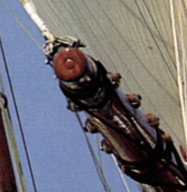
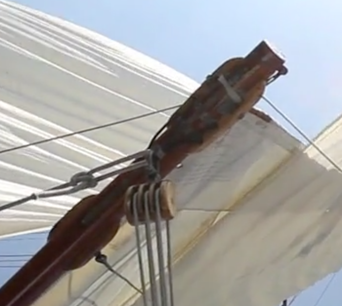
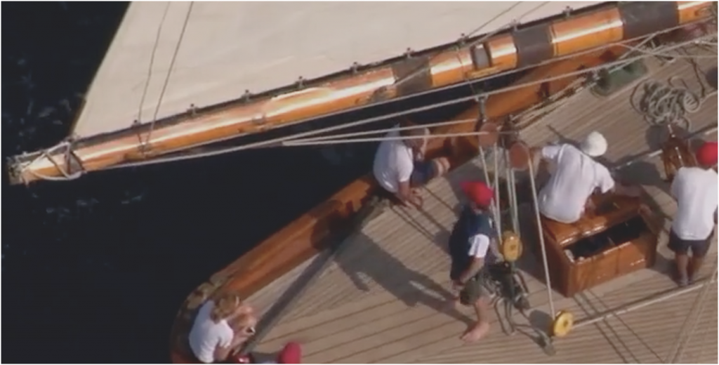
Thank you John. Richard - I have used that video a lot. The image at 2.15 is a bit vague so requires some interpretation. It's the image below - cleaned up as best I can using photo processing I am assuming that the main boom shares some common design features but I can't see any signs of the outhaul on this image. The image that Infer the design is the one below. The tight line that is below the boom passes through the pulley before winding on to the mast winch. I'm not sure what this would be for if not an outhaul. However to add to the mystery I also have this image which shows a twin (triangular) rope arrangement going back to two eyes on the ring at the end of the boom. I bet someone will have a good explanation for the images?????

-
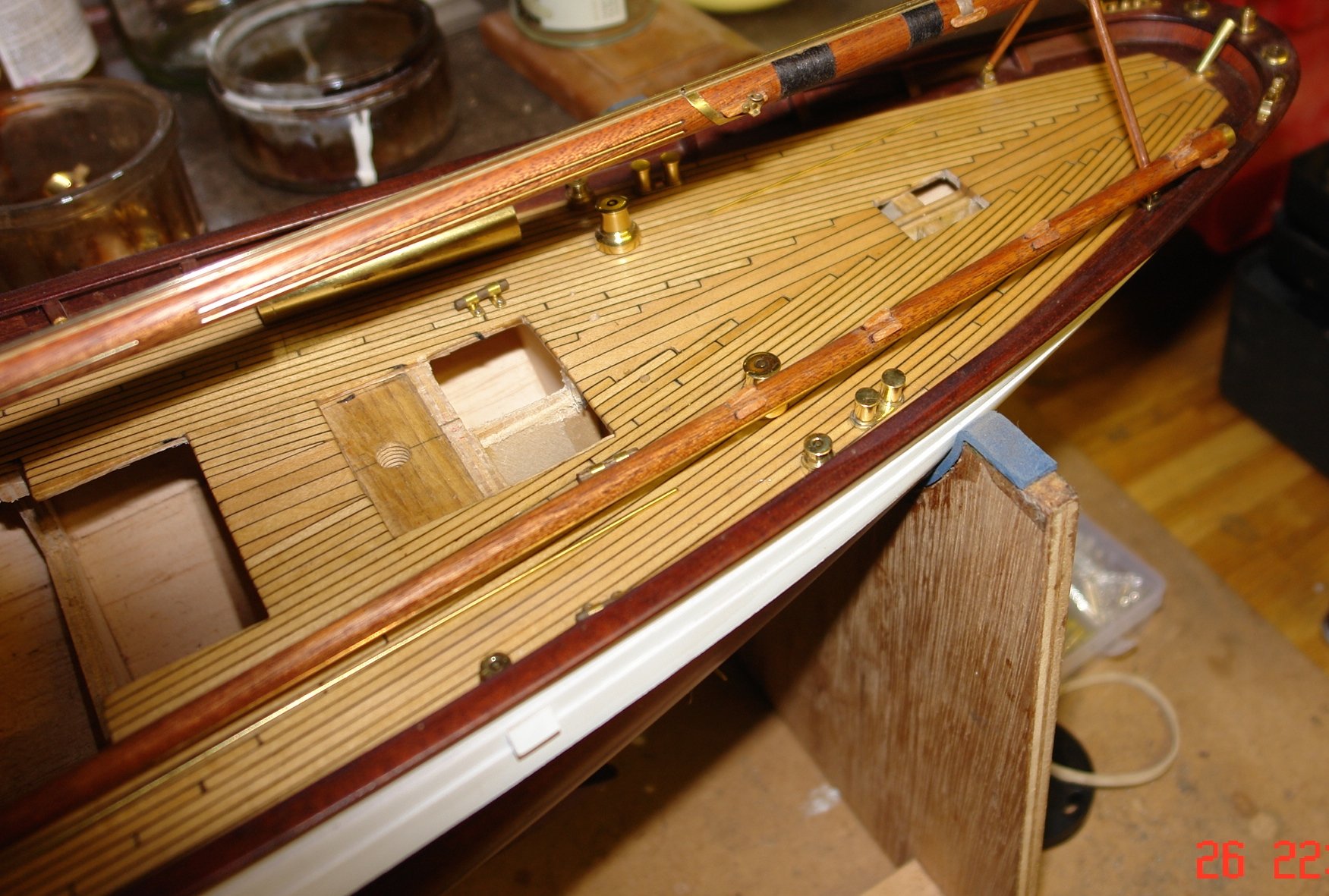
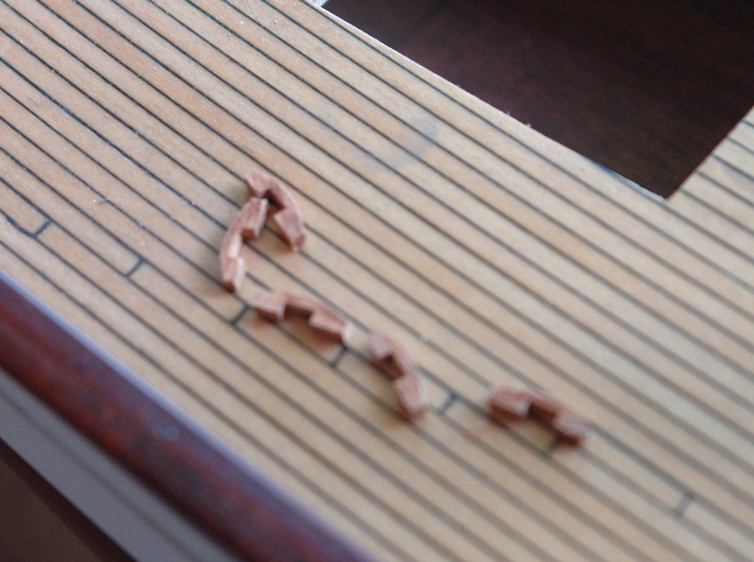
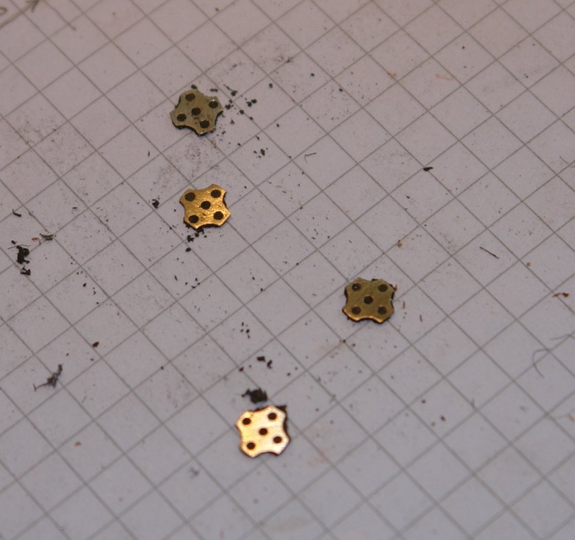
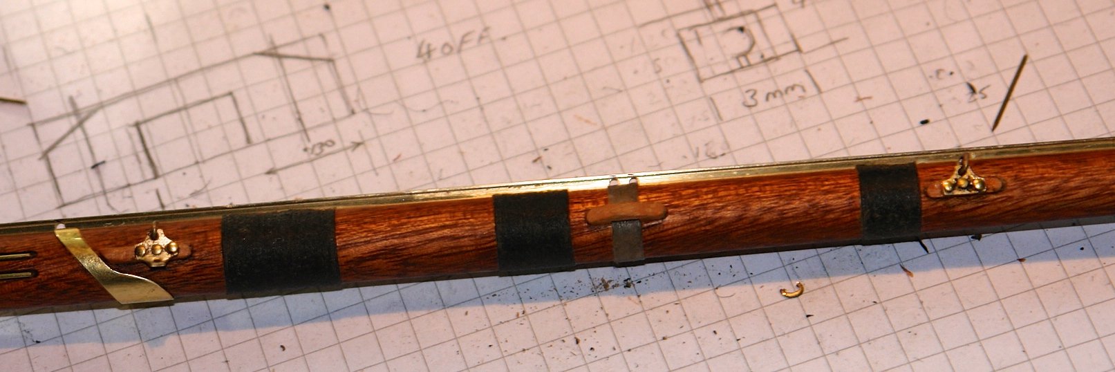
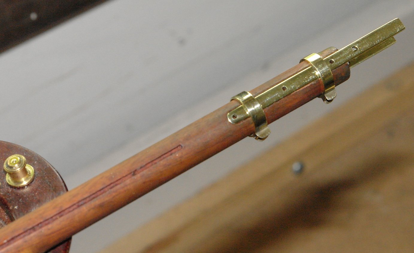
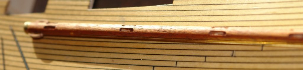
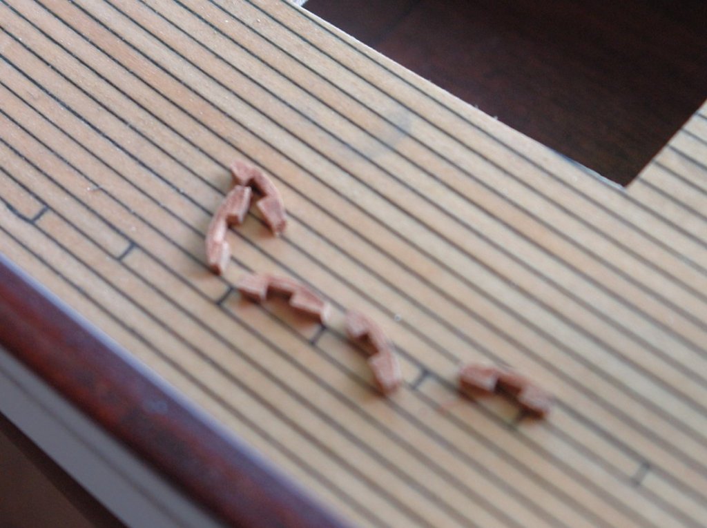
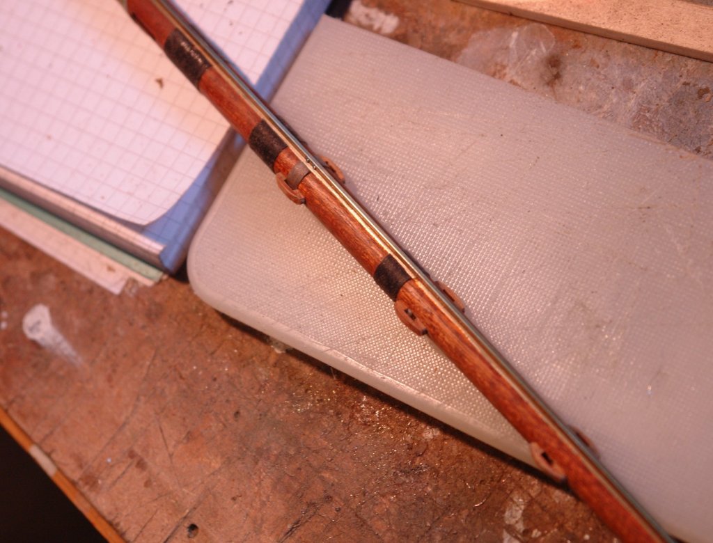
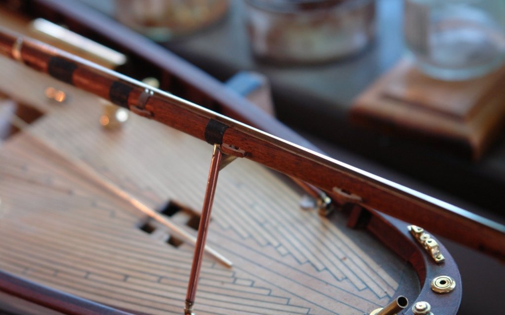
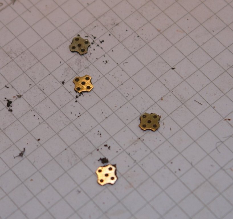
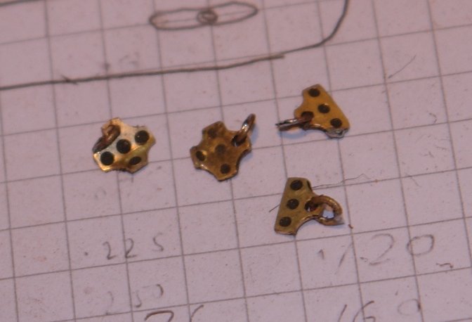
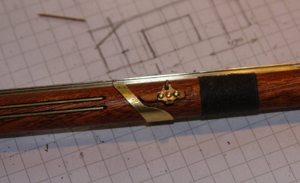
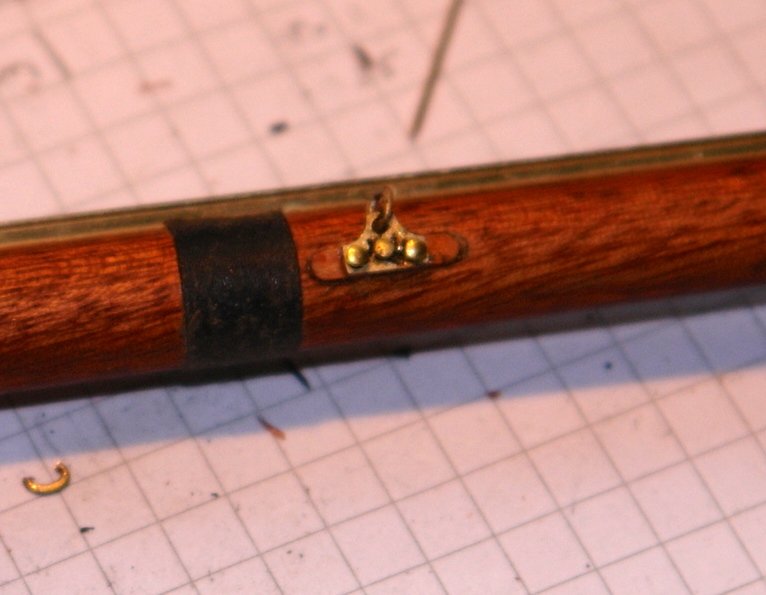
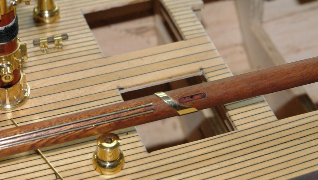
Richard, Greg , Per. Thank you. Further progress on the boom:- The detail at the end of the boom is minimal both on the plans and on the web. The mainsail must have an outhaul line and on some photos I can see a line running the length of the boom to a block and winch on the main mast. I surmise that this is the outhaul in which case the end of the boom must have some sort of pulley wheel. I decided therefore to slot out the end of the boom to take a .25" dia x .04" wide sheave. The boom has 4 bindings at positions along it length. One is grey while the others are black. A raid of my wife's sewing box produced the required thread and I wound it by pacing the boom in the lathe (rotating at 60 rpm) with the thread being hand fed. I fixed it in place by wiping on some CA glue. The binding was then cut away across the slot (milled earlier) to take the track. The track was then machined to fit over the various boom fittings and holes were drilled in it to pass through the various strops and lines. The track was glued into the slot using CA glue. The end of the boom was then finished by adding a further strop rubbing strip, sheave and end reinforcing hoop. Along the boom are various attachment points which were made from mahogany. I also needed to make an attach some very small (at model scale) brackets. These were cruciform in shape and were made on the mill. They are about .2" x .2". The brackets were then attached - pinned in place and glued with CA. Every time I look at the boom I find more detail. I thought I had finished but then discovered a couple of cleats mounted at the mast end. A job for tomorrow!!! I also need to think about making the 60 sliders which are approx .080 inch wide and need to be slotted to run on the track. They are complicated little devils and I need to work out how best to produce them efficiently.


-
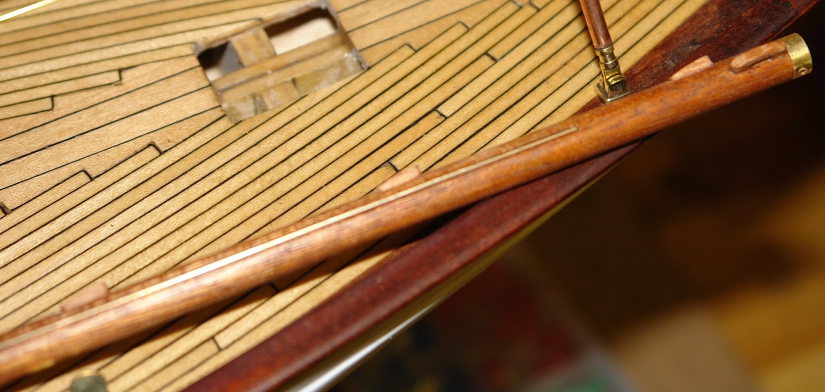
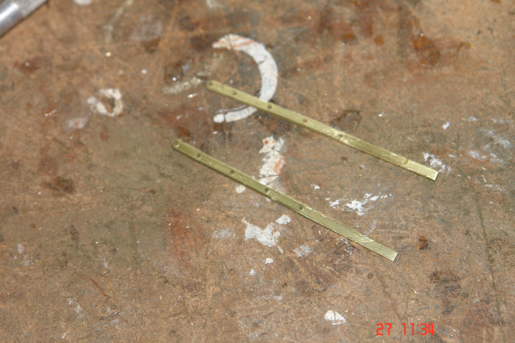
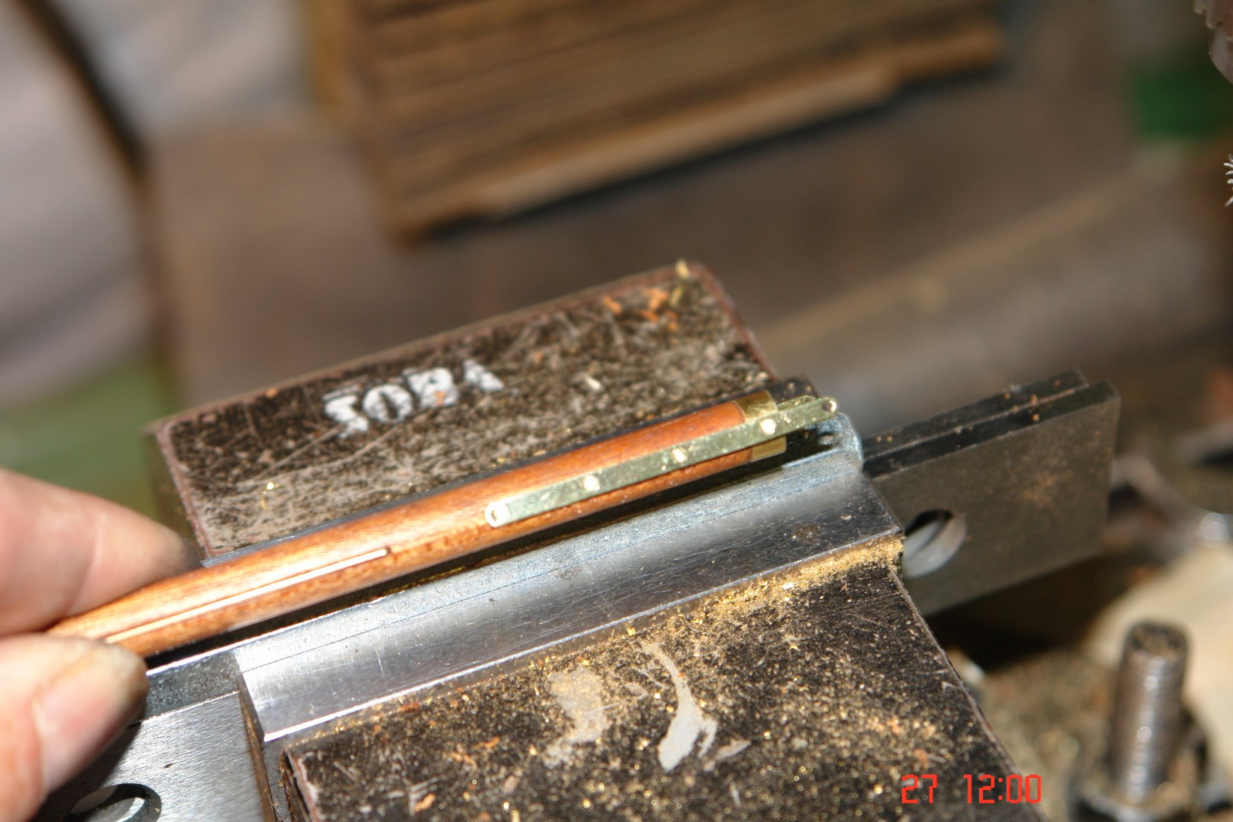
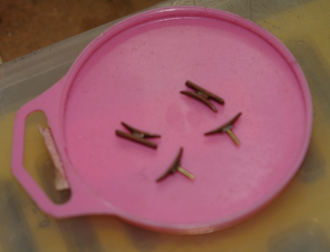
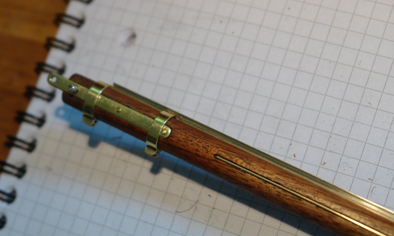
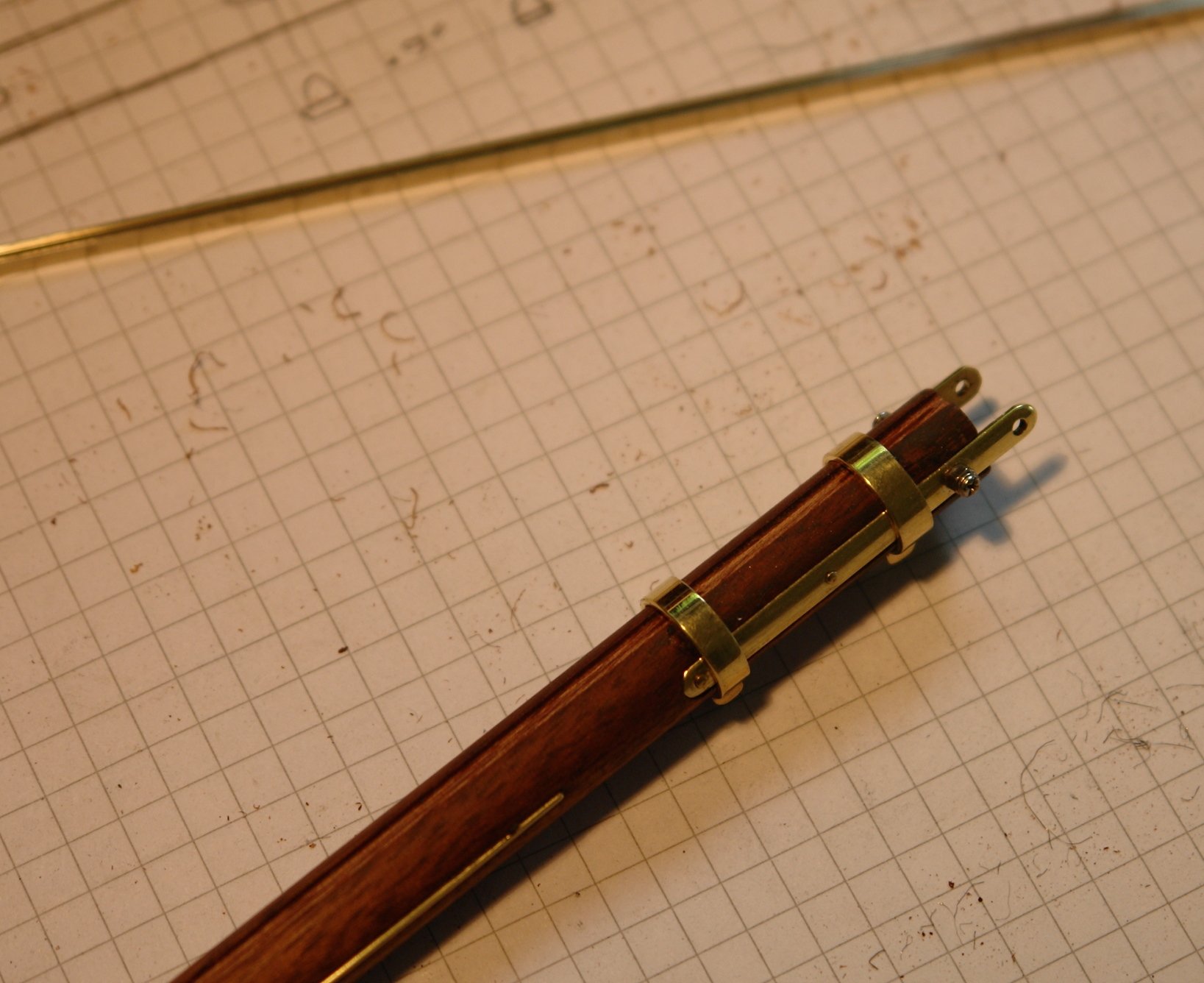
After a bit of an enforced break I managed to get a couple of days in the shop for the first time in 2 weeks. I started from where I left off with the machined main boom. I needed to make the straps which attach the boom to the goose neck and the hoops which hold them in place. Because the straps fit inside the hoops the outside surface needed to be filed into a curve. I machined slots into a turned bar to hold the straps and act as a filing guide so I could get the correct shape. The hoops were turned on the lathe and the flanges were simulated by soldering on a bit of U shaped channel. The straps are .100" wide to give some idea of scale. The assembly was finished by simulating the rivets using pins and making the securing bolt from my pack of spectacle repair screws and nuts. I then cut some .025" diameter brass wire and inlaid it to simulate the rubbing strips. The boom also has rubbing hoops where the boom strop bears against it. These were cut from tube, partly on the mill, before finishing with a piercing saw and needle file.


-
its a bit late now but it might be worth noting for the future. Mix a little body filler and spread it thinly with a flexible (plastic) spatula - about 1.5 to 2 inches wide. Limit the area being filled to about 4 inches by 8 inches. This should mean that you get the mixed filler on before it starts to go off. Rub it down until smooth using a coarse emery cloth - 60 or 80 grit. Apply another thin coat and repeat. Carry on this way until the whole hull has been done - it may take 15 to 30 applications. As you reach the later applications you should move to finer emery cloth 120 to 180 grit.