
Supplies of the Ship Modeler's Handbook are running out. Get your copy NOW before they are gone! Click on photo to order.
×


Cathead
-
Posts
3,378 -
Joined
-
Last visited
Content Type
Profiles
Forums
Gallery
Events
Everything posted by Cathead
-
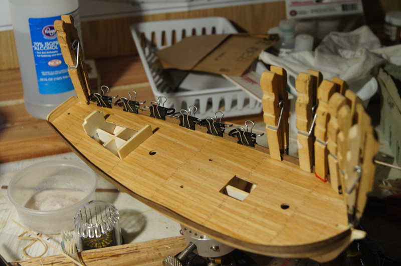
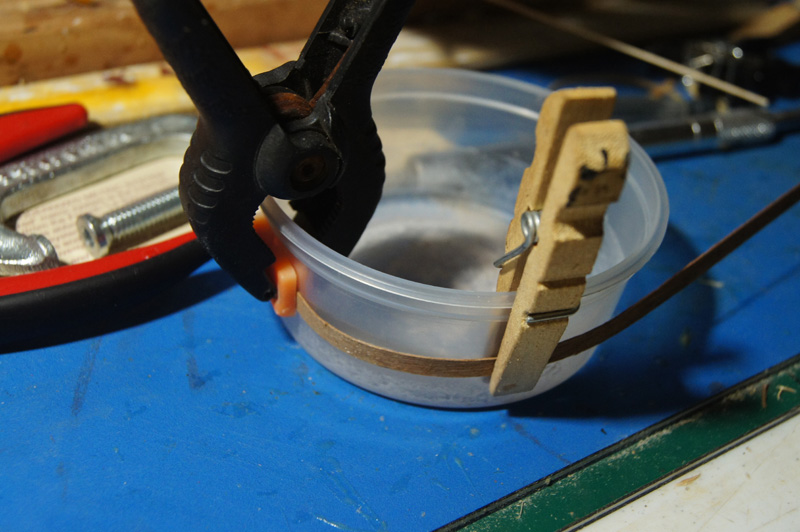
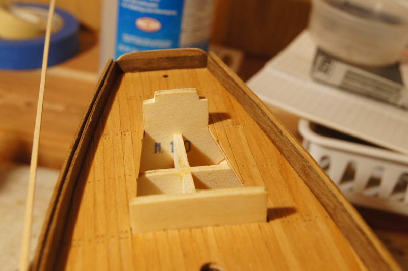
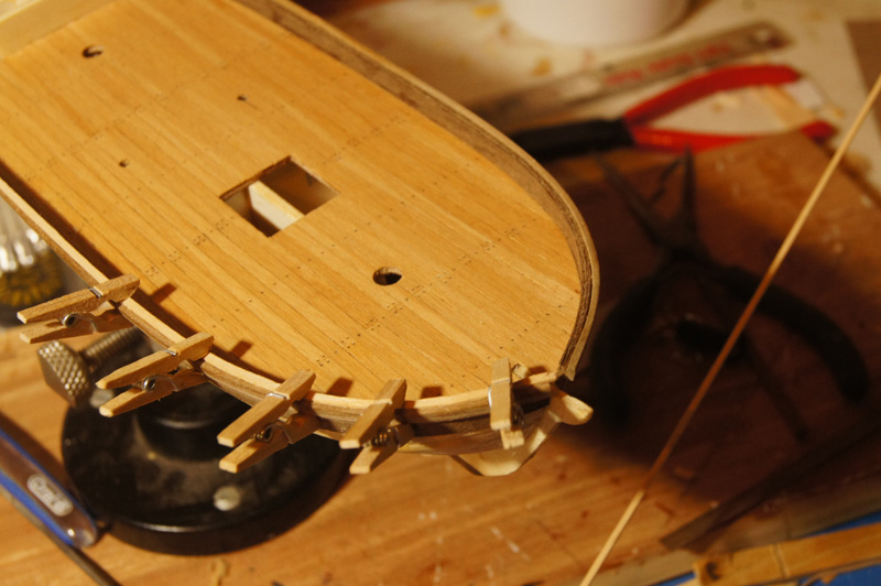
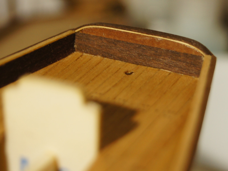
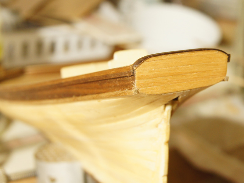
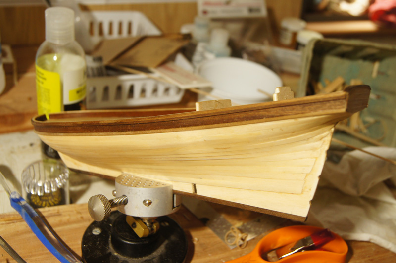
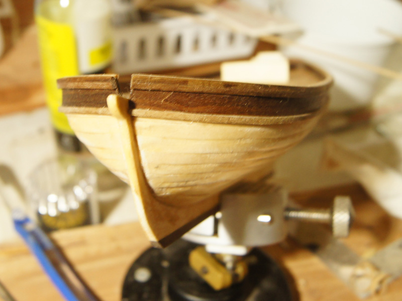
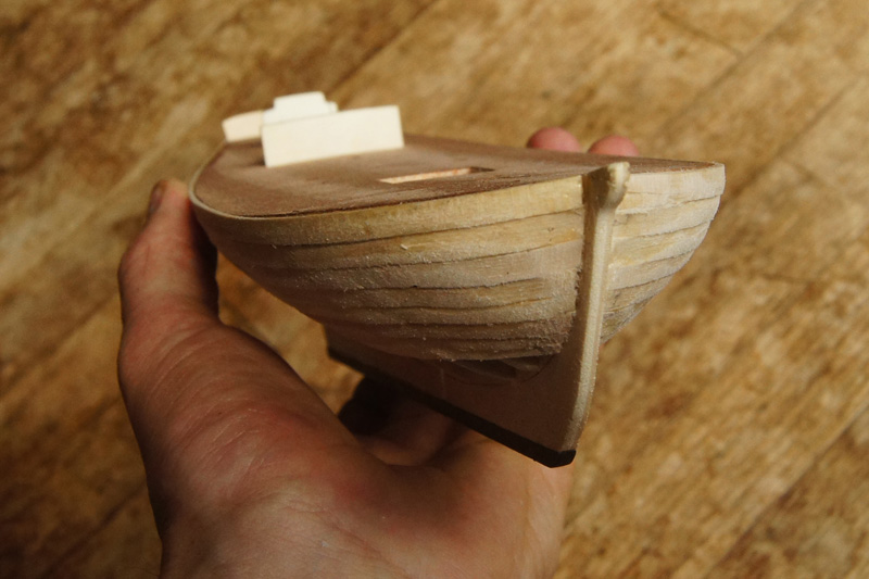
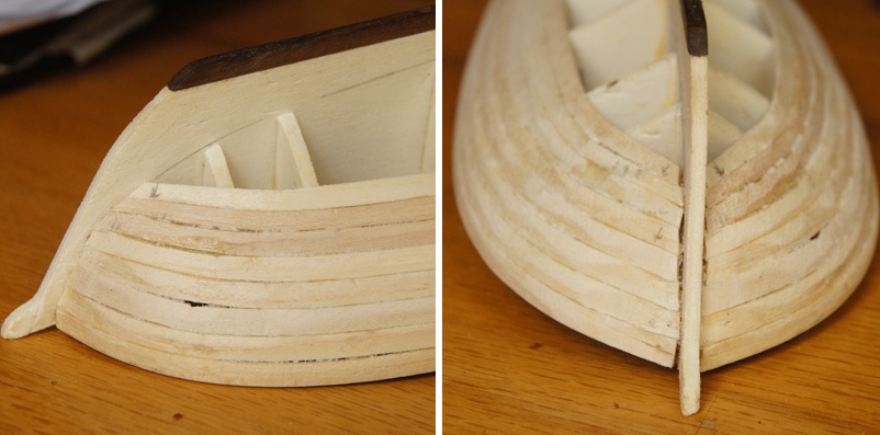
 Bulwarks, wales, and transom This was an interesting process of adapting my skills and intentions to poor instructions and kit layout. Lots of photos below. The bulwarks begin by gluing two thin strips of walnut together lengthwise, overlapping halfway. You're then supposed to bend and glue these to sit over the edge of the deck, so that the lower strip forms the first strake of planking and the upper strip sits inboard atop the deck. The photo above sort-of shows this cross section, along with the beginning of my take on the transom. Here's another view. Look at the starboard rail, and you'll see one reason why I don't like this approach: it's really easy to get waves or dents in these thin strips as you try to attach them firmly to a narrow strip of the hull. I'd prefer setting up thin stanchions first and gluing strips to those. This photo actually shows the next step, adding several more layers of thin walnut inside the outer bulwark to stiffen and thicken it. Here's how I bent these strips, using a plastic dish with about the same radius as the bow, soaking the strips overnight, then clamping them into a curve until dry. This thin walnut is really prone to breaking, and the kit offers no extra material, which has been an annoyance throughout the build so far. I had to glue several strips back to together after they shattered, and attempt to hide the joint as I had no spares to replace them. After you're done with this, you're supposed to have a ledge on the outboard side, along which you run two thicker square strips of walnut to widen the top of the rail. The directions show these two strips lining up perfectly with the inner bulwarks to make a nice, smooth surface. They don't. In the photo above, you see the significant gap remaining between the top of the inner bulwarks, and the much higher outer line of square walnut strips. This was most annoying, and I decided I had to fill that gap with wood to bring the whole thing level. Having no spare walnut, I had to use scrap basswood from my stash. I didn't think this would matter, as this whole assembly gets painted anyway. Here I'm inlaying the basswood at the bow, after bending it to a proper curve. On the port side, you can again see the gap I'm trying to fill. Interestingly, by the time I'd finished and sanded everything smooth, it ended up looking really good! The thin basswood strip sets off the darker walnut nicely, and Mrs Cathead cooed when she saw it. "You're not going to paint over that, are you?" Hmmm. So after some thought, I decided to see if I could finish the above-deck area as natural wood. I formed a transom to my liking, and laid a strip of basswood then a strip of walnut across the upper curve, which also turned out nicely, blending the basswood inlay along the rails with the walnut exterior. I planked the stern with scraps of remnant decking, and smoothed everything to fit. It's not the transom I set out to make, but I think it works. I still can't easily envision the 3D geometry of the curved transoms some of these craft had, and since this is a fictional one anyway, I'm going with what looks pleasing to me. So here's how she looks now, with the first line of the wales attached. I rubbed everything down with a natural wood oil I use on my kitchen counter, to protect and darken the wood (actually, the lower wale hasn't been oiled yet, so it looks lighted, which shows you the difference). I like the effect, and so does Mrs Cathead, my primary audience. I should have taken a higher-angle photo of the basswood inlay inside the rails, but you can see a hint of it.
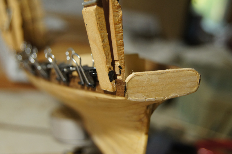
- 96 replies
-
- 9
-

-
- topsail schooner
- revenue cutter
- (and 3 more)
-
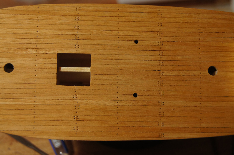
Finishing the deck Here's how I finished the deck. I embossed small holes into the deck planks, using a smaller nail than in my tests above, and gently filled each by pencil. This kept the pencil mark just below the sanding level, so I could finish the deck without smearing anything. Once I was done, I sanded and oiled the deck. I had to decide on a treenailing pattern, and you can see what I went with. I first just did the plank ends, but it looked wrong as the lines of treenails just had too much open space between them. I assume in reality these planks were attached at every deck beam, but I thought that would look too busy at this scale. So I made a single line halfway between each line of joints. To my eye, it balances the appearance of the deck and I'm pleased with the outcome. The only downside is that despite using a straightedge to lay out the planking, I clearly didn't do a perfect job and some of the joints wander a bit. I think this won't be noticeable once the model is finished; it stands out now because the deck is wide open.
- 96 replies
-
- 6
-
-
- topsail schooner
- revenue cutter
- (and 3 more)
-
Any jigs/suggestions for coiling gun rigging rope on decks?
Cathead replied to MartinJ's topic in Wood ship model kits
I agree with Dylan, the double-sided tape works fine. You do need a reasonably strong tape; I switched brands and the new one isn't strong enough to hold the line down. Also, don't over-coat the coil with glue, or it'll soak down in and glue the coil to the tape, making a mess when you try to remove it. And yes, it's far easier to make coils on the bench and install them. Same goes for "hanging" coils like those on belaying pins. -
Almost done! You're doing a fine job.
-
Based on my experience, I think you should fair the bulkheads a bit more, until most of the laser char is gone. Particularly at the bow, I can see half the bulkhead width of char still there. That implies that half the bulkhead is still essentially flat, with the other half tapered to hold the curve of the plank. You're going to want that whole thing faired to support the curve of the plank; not only is it more surface area to attach to, but the change in angle across the face of the bulkhead could actually give you a dent in the plank. Also, I can see that the char line wanders back and forth quite a bit, particularly near the stern, which implies that your fairing isn't even, which again could cause you problems down the road. You want a smooth, consistent angle along the whole face of the bulkhead, not one that stops halfway across or changes along the curve of the bulkhead. Having the bulkheads perfectly aligned or not isn't structural problem that should concern you, other than the final look of the model (it would look strange to have a frame leaning one way or another). But getting the fairing right will definitely make your planking easier and better. You absolutely want and need to have the plank glued to every frame, so having the best surface possible to do that, and to ensure that each plank matches best with the one above and below it, will help you achieve that. You've made a nice start to this kit, and are clearly taking your time and thinking through your steps. Bravo! But I would go do a bit more fairing before you proceed.
-
whats an easier build for a first kit
Cathead replied to rdestefano01's topic in Wood ship model kits
Build a small open boat first. It'll take you a few months, and you'll get a feel for the skill sets involved in a much larger project without investing so much time and money. Why be in such a hurry? A large ship will take you years anyway; the few months it'll take you to build something simple will never matter in the end, but will really help you prepare. There's no possible downside. If a builder can't delay gratification a few months, they'll never finish a large ship model anyway. -
druxey, there's a reason the vast majority of western river boats were built on the upper Ohio River: vast tracts of Appalachian forests right on the boatyards' doorstep. Not to mention the coal mines that fed the metal-working industry of Pittsburgh. Lovely work, Glenn. The longitudinal bunks are an interesting comparison to other boats.
-
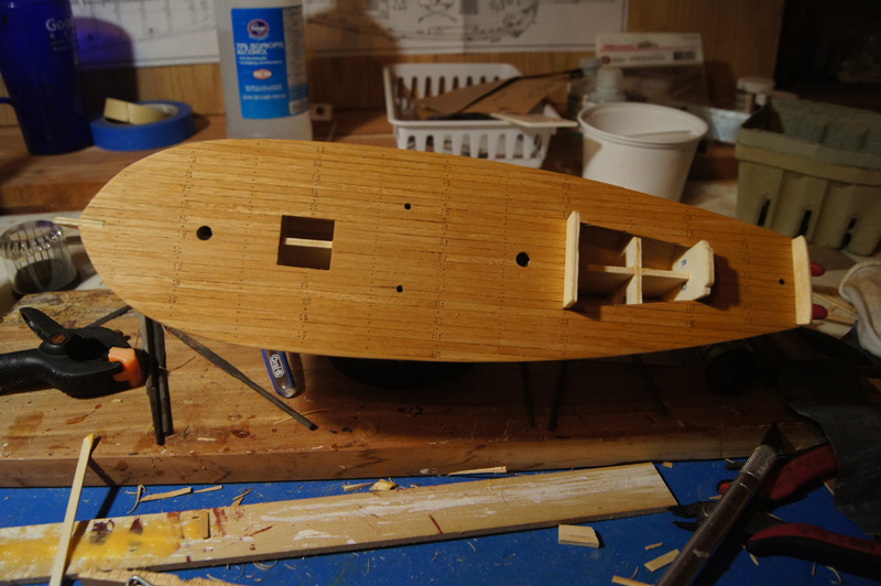
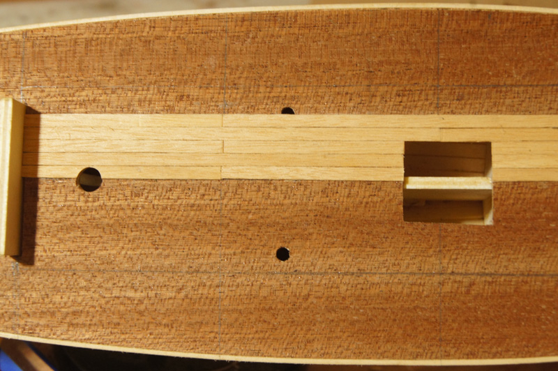
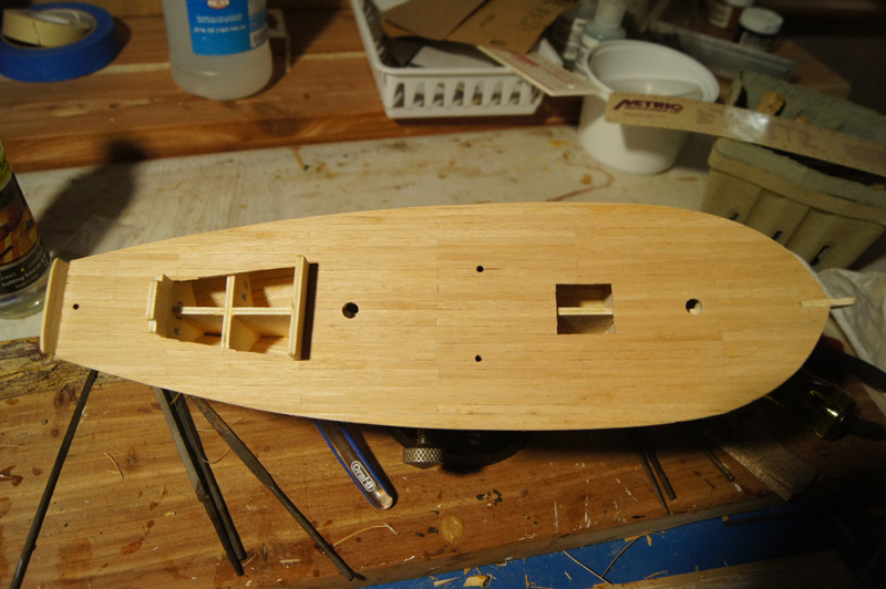
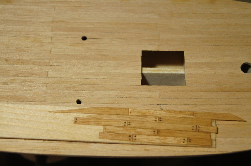
Stage 5: planking the deck and bulwarks I'm not terribly impressed with the wood quality supplied for the decking. It's cut very roughly along the edges, necessitating a fair amount of sanding to get a smooth edge sometimes, which then makes it harder to arrange tight joints between deck planks. I began by drawing a square grid on the plywood deck, to help guide my planking. The plans show a fairly short plank length, which looked too busy to me and contradicted what I'd read elsewhere about planking normally running 20'-24' in this period. So I cut my planks to about 20' instead. I started at the stern along the centerline, and worked my way forward and out. You can see my grid in the second photo. Wherever I overlapped a hole (for masts or other purposes), I stopped when one plank crossed it, filed out that side of the hole, then kept going, filing the remainder when the next plank went in. This way I didn't have to drill anything and risk cracking the wood. Here's the finished deck before sanding. I think it came out nicely. Now I'm considering whether, and how, to simulate treenails (or the bolt and plug equivalent). The photo below shows one test, using thin holes filled with pencil, the seams gently lined with pencil, and the whole thing sanded and oiled. I'm trying to decide if it looks good, or out of scale and too busy. While researching treenail approaches, I ran across one mildly embarrassing thing. I'd followed the plans' approach to plank pattern, just alternating butt ends back and forth. Seems that a more prototypical way is a four-stage staggered layout, which is eminently sensible from an engineering point of view, but like a fool I just followed the plans again. So the deck may not be right to an expert, but at least it's visually pleasing (to me, anyway). Once I decide, I'll finish the deck, then construct the bulwarks. Only then do I go back to planking the second layer on the hull. Anyone have thoughts on the test approach to treenails?
- 96 replies
-
- 9
-
-
- topsail schooner
- revenue cutter
- (and 3 more)
-
Just now catching up on this build, and will add my amateur 2 cents that you're doing a wonderful thing, and a wonderful job. Thanks for being an inspiration.
- 2,191 replies
-
- 5
-
-
- confederacy
- Model Shipways
- (and 1 more)
-
The first planking is done; I simply filled in the remainder letting the planks run as they desired, not worrying about prototypical accuracy. It'll all be covered anyway. The photos below show it before any further sanding or filling, so it looks especially rough. Next, I sanded it down to a smoother finish, and rubbed the whole thing with wood glue. This filled in the gaps, and soaked into the planks, creating a much smoother, stronger shell that I then re-sanded. I consider the final result acceptable. It's still obvious that the planking pattern isn't right, but I now have a smooth shell in the hull's shape that should be a good surface for applying the second planking. I didn't take further photos because I don't think it'll look much different to the lens, and you'll see the finished surface again once I start the second planking. In the meantime, the next step is planking the deck, which is off to a good start. I'll post photos when the process is completed, it's pretty straightforward. Thanks for reading.
- 96 replies
-
- 7
-
-
- topsail schooner
- revenue cutter
- (and 3 more)
-
Looks very nice. I definitely like your choice of color scheme.
-
Mike, I'm pretty sure the upper decks were covered in tarpaper or canvas, beneath which they were planked as usual. I think Kurt will have some suggestions for how to achieve that effect.
- 225 replies
-
- 3
-
-
- chaperon
- model shipways
- (and 1 more)
-
Steamboats and other rivercraft - general discussion
Cathead replied to Cathead's topic in Nautical/Naval History
Sal, that's a great insight! Seems very sensible. Don't know what to think about aesthetics, as it's so subjective. I do wonder whether they'd add a much larger box just for appearances, given how much weight and top-heaviness mattered to these boats.- 281 replies
-
- 4
-
-
- Steamboats
- riverboats
- (and 3 more)
-
Steamboats and other rivercraft - general discussion
Cathead replied to Cathead's topic in Nautical/Naval History
Pete, The core question here started with the rounded arch atop the paddlebox. I fully agree that a wider-than-minimum box makes sense at the level of the main deck, for everything from repair to debris to splash, but none of that explains the very wide arch at the next level up. Likely no one's crawling into that upper arch to do anything, why would they when you can just rotate the wheel 1/4 turn and work on it at the main deck level? But instead they still built the arch at the boiler deck level much larger than the wheel, which took more timber and added more weight, a significant choice given that these boats were very sensitive to both total weight and top-heaviness. Mark, I don't know for sure either. That's what makes it fun and maddening!- 281 replies
-
- 4
-
-
- Steamboats
- riverboats
- (and 3 more)
-
Steamboats and other rivercraft - general discussion
Cathead replied to Cathead's topic in Nautical/Naval History
Mark, it's my understanding that few western riverboats used variable-angle buckets on the wheel. Conditions were just too rough for them to work properly. Also, did these wheels turn fast enough to really splash water that high? These were geared for power, not rapid rotation, and I wouldn't think they'd spray water except near the surface. By the time the wheel had rotated toward the upper portion of the paddle box, the water was almost certainly mostly drained off the bucket. I could see allowing for extra space at deck level where the wheel first hits and emerges from water, but I'm trying to envision the need tens of feet up at the top of the arc, where this discussion is focused.- 281 replies
-
- 3
-
-
- Steamboats
- riverboats
- (and 3 more)
-
For context, nearly all of Bertrand's decking was preserved intact, and the archeology team mapped every plank. Most look to be 20-25 feet long, with a somewhat chaotic planking pattern that seems to fit the backwoods construction. Widths are pretty variable, too, again fitting the way a lot of early steamers were built. Given that Bertrand was built 30-odd years before Chaperon, I don't know how much decking methods changed in that time, I don't know much about these late steamers. I'd guess they were more standardized by the late 20th century. But that's at least some context for you. At scale, 20-25' comes out to roughly 13-16cm or 5-6 inches.
- 225 replies
-
- 4
-
-
- chaperon
- model shipways
- (and 1 more)
-
The photos are very helpful. It does like nice as it is. To my eye, it's too uniform and shiny, I find that subtle variations in color and finish make a model look far more realistic than a uniform finish, even if the latter is technically more accurate. So if you keep it, I'd try to dull and vary the finish a little bit, maybe with careful application of pastels or something. Make every few planks a slightly different shade, or more weathered, or something. But unlike a sailing ship, much of the deck will end up obscured, so maybe it doesn't matter. You could focus that effort only on the bow and other areas that will remain exposed. Those toothed joints between panels do stand out, but again most of that area will be covered, so I suspect that a few crates and barrels would take care of the rest. Does that deck have any plank ends? From the images, it looks like just a continuous run. It's probably too late to scribe in some plank joints, but that would give it some extra nice detail and variation as well, and is something that would happen naturally if you replank it. Honestly I'm torn. It would be a lot of work to replank what is a good-looking deck, and most of your work would be obscured (Chaperon has far more enclosed space than Bertrand did). I guess I'd say do it if you want the experience and the extra work and detail, but what you have would look plenty good with just a little finishing.
- 225 replies
-
- 3
-
-
- chaperon
- model shipways
- (and 1 more)
-
I posted this question over in Steamboats and other Rivercraft, so we don't fill up Glenn's log with too much speculation, partly to absolve myself from starting the speculation in the first place.I figured it's a general enough topic that the discussion and answer might fit well over there.
-
Steamboats and other rivercraft - general discussion
Cathead replied to Cathead's topic in Nautical/Naval History
Discussing the size of paddleboxes on sidewheelers? Recently in a build log, the question came up of why the paddleboxes on some sidewheelers are so much bigger than the wheels themselves. It's a very interesting question, which started to generate theories, so I thought I'd bring the topic over here so avoid cluttering the original log. Two suggestions mooted so far were: Anyone else have ideas or insight?- 281 replies
-
- 3
-
-
- Steamboats
- riverboats
- (and 3 more)
-
Here's an idea on the paddlebox: is the extra space to allow for the possibility of debris caught in the wheel? Most western rivers had a lot of woody debris (branches, logs, etc) and I could see a moderate-sized branch getting caught up between two buckets and being lifted up into the paddlebox, where it could do some damage to either the surrounding shell or the wheel itself once it gets wedged in there. Maybe the extra radius reduces the likelihood of this? Otherwise I'm quite interested to know what Kevin or other informed persons say.
-
Yes, Mike, I was talking about the toothed joints between deck panels, not the planking lines. Apologies for any confusion. What about setting small metal pins into the bottom of any post/tab that's supposed to fit into the deck, then just drilling tiny holes into the new deck for those pins to fit into? Could be hard to get the alignment just right, but probably no harder than actually fully redrilling so many holes then shaping them properly. Apologies if I'm overdoing the ideas; my mother has the same habit of constantly offering advice even when unwanted; I get the solving-others'-problem gene from her.
- 225 replies
-
- 4
-
-
- chaperon
- model shipways
- (and 1 more)
-
Mike, if you think only a few of those seams will show, you could always consider hiding them under a few loads of cargo (barrels, boxes, bales). That's a long-standing model railroad tradition for hiding oddities in work; many layout buildings with vines creeping up the walls look that way to hide a flaw in the paint or siding! If you decide to replank, those holes are a concern. Not knowing how the kit is set up, would it be easier to drill circular holes, then round the bottom of the posts or tabs that fit into them, rather than trying to square off lots of holes?
- 225 replies
-
- 3
-
-
- chaperon
- model shipways
- (and 1 more)
-
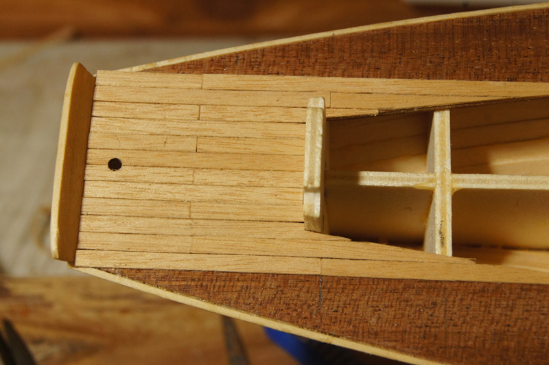
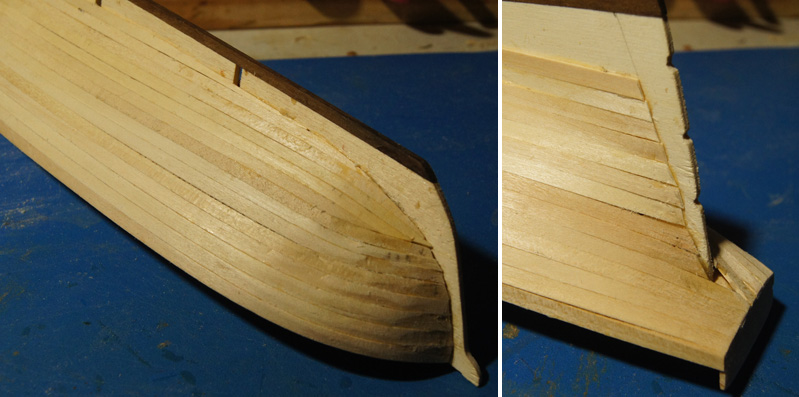
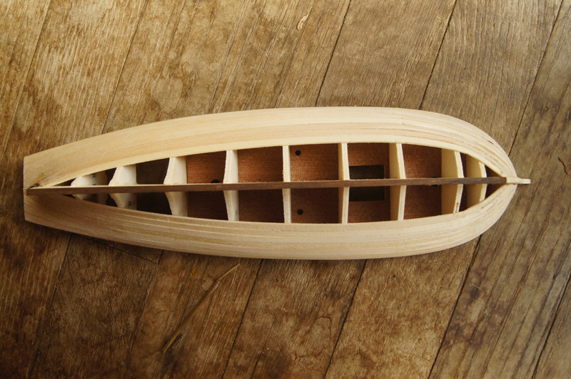
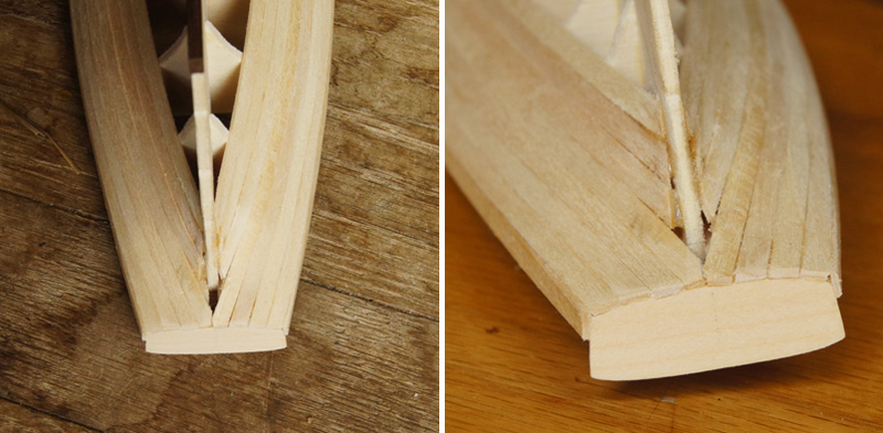
Stage 3 continued Welcome to "How not to plank a hull", by Cathead. I foolishly decided to follow the instructions' recommendations and diagrams for planking the hull, and have now concluded that that was a bad decision. Among other things, they tell you not to start tapering planks at the stem until the 6th strake, which is definitely not the right approach. In attempting to do so, I ended up doing quite a lot of extreme edge-bending and shaping, which produced some planks far too crinkled and buckled for my liking. I should have followed more normal guidance for hull planking from the start, with a lot more tapering right from the beginning. Luckily, this is only the first planking, and I've learned quite a bit about how planks will and won't lie on this hull form, giving me confidence I can do a much better job on the second planking. The first two photos show it in a moderately positive light, hiding some of the worst of the work. You can see the uneven run of the planks and some buckling, but once it's filled and finish-sanded I expect it'll provide a sufficient surface for the second layer. Sticking with the positive thinking, the stern has been less troublesome so far. I cut out a smaller transom support that fits the hull, imitating where the horn timbers would support the shape of the transom. I planked around the edge of it as various resources have appeared to suggest I should do. When the second layer goes on, and I plank both sides of this support, I'll extend it farther out in a curve to match contemporary images. I'm also thinking of adding an outside structure in the shape of the horn timbers, like you see in the image of USRC Louisiana I linked to above. I'm happy with the run of the planks here overall, but it did take some modification from the kit. The last few frames are too large, guiding the planking away from the stern, forcing a sharp bend inward to meet the end of the stern. I carved and sanded these last few frames down significantly to achieve a smoother run, and I probably could have done even more. You'll see that I still had trouble getting a couple planks to fully lie against the stern, they pulled away slightly despite pre-forming and sanding. But this is way better than if I hadn't cut down the frames. Again, I think filling and sanding here will produce a good surface for the final planking. And here's the embarrassing part. That's some ugly work right there. For too long I stuck to the original plans, telling myself that if I just kept going it would work itself out. It didn't. Given that this will be hidden forever, I've decided to change course and just fill in the remainder with planks cut to fit, rather than bent to fit. It will look ridiculous and inaccurate, but as it'll be hidden by the second layer, it'll make the work go faster and more happily. I've learned the lesson I needed to, and don't need to beat it in any further. For the second layer, I'll lay out proper planking belts and be more attentive to shaping and tapering planks. If I still don't do a good enough job, I'll consider coppering the hull (as shown on Louisiana), which will cover 90% of the surface anyway on this low-slung ship. So other builders be warned, don't be like me and try to force your way through bad instructions. Just plank the thing following the better guidance available elsewhere. I'll update again when the first layer is done. Thanks for reading, and controlling your laughter!
- 96 replies
-
- 9
-
-
- topsail schooner
- revenue cutter
- (and 3 more)
-
Mike, Looks great so far. I'm a bit late to the deck-painting discussion, but here's one other method I've used before. Use a cotton swab (Qtip) with diluted paint. Get the swab wet, press out the excess paint liquid against the side of a container, then use the swab to rub the color onto the wood. If you get it right, this allows a transfer of diluted color that's less sloppy than a brush, as you're essentially using the swab as a sponge, so it retains more moisture than a brush does. Certainly experiment on scrap first to get the hang of it, but I like it. I love the idea of replanking the deck, but it's not my model!
- 225 replies
-
- 3
-
-
- chaperon
- model shipways
- (and 1 more)