


Cathead
-
Posts
3,524 -
Joined
-
Last visited
Content Type
Profiles
Forums
Gallery
Events
Everything posted by Cathead
-
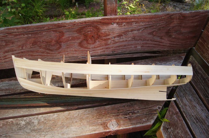
 This may be a trick of the photo, but to my eye it seems that your sheer plank doesn't quite curve smoothly along the whole run of the hull. At about the 7th frame from the stern, there seems to be a sharper curve transitioning from relatively straight sections fore and aft of that point (especially fore). I mention this, not to be critical, but because if this isn't an optical illusion it may give you trouble as you continue planking. Ideally that plank should follow a smooth, sweeping curve with no sudden changes; any of those later could ripple through the subsequent planking and give you wider gaps between the planks or more difficulty getting the planks to really follow the hull smoothly. My apologies if it's just optical or if suggesting this is out of line, but I've always hoped others would point out potential concerns to me and wish to do the same for others.
 -
review BlueJacket Shipcrafters Lobster Boat: A Review
Cathead replied to Cathead's topic in REVIEWS: Model kits
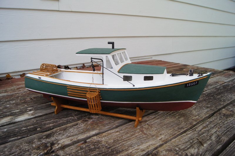
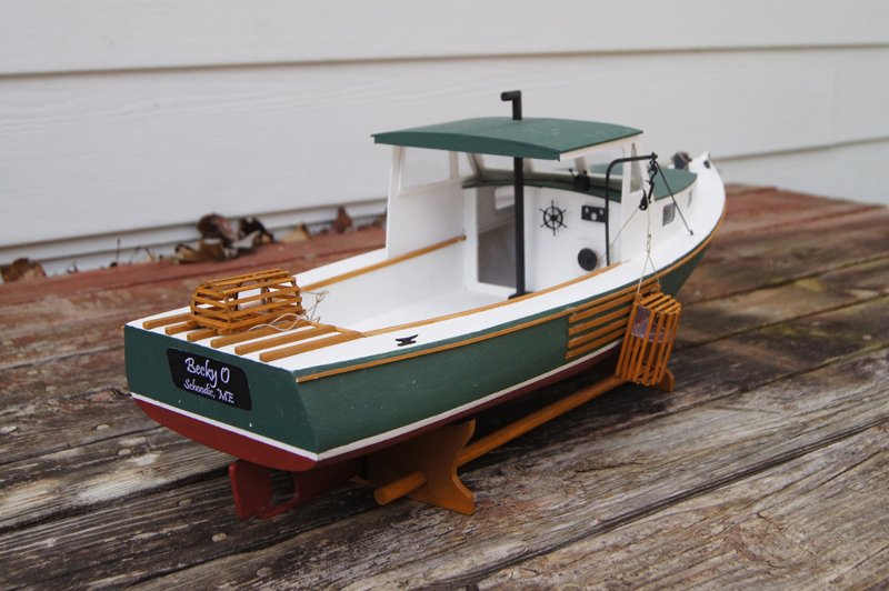
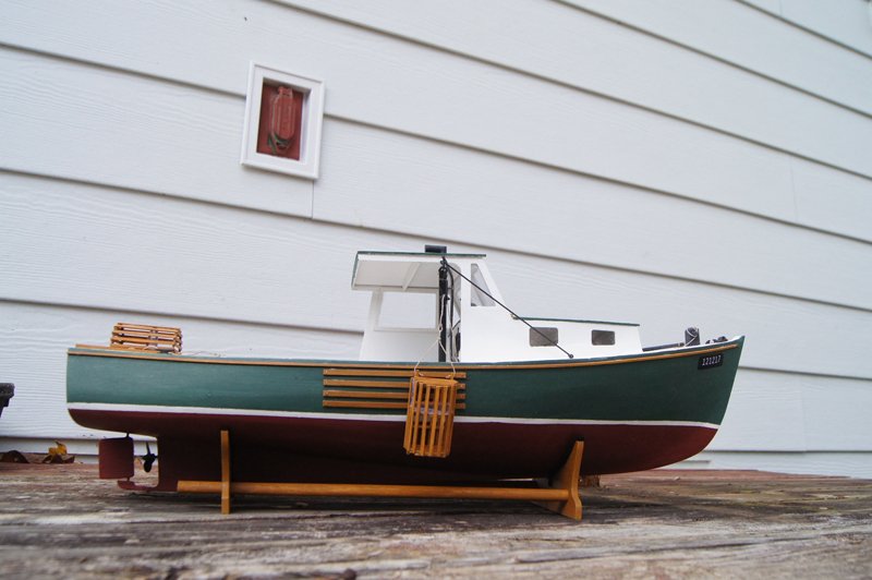
Nice, Kurt, thanks for sharing! Your extra detail looks especially nice. Your shade of green seems more marine, but I chose the exact color scheme I did because it's quite literally the same as our house. After I rejected the kit paints, I decided to use the house paints I already had on hand for our siding and trim as I'm budget-conscious and really didn't want to order yet more paints (I wish I'd thought of that in the first place). I know that house paints are generally not good for models because the texture is so much coarser, but given the large scale and low detail of this particular kit, I thought it would work well enough, and as it's a gift for my mother any subtle reduction in textural quality is overruled by the "cool" factor of a meaningful color scheme. If you look closely you can see the texture isn't ideal, but it looks great from more than a foot or so away, and that's good enough for me on this one. Next up I'm finally getting back to my long-delayed steamboat Arabia project, which has been languishing all summer. It's still in design mode but I'm close to actually doing some physical mockups that will help me move forward. -
review BlueJacket Shipcrafters Lobster Boat: A Review
Cathead replied to Cathead's topic in REVIEWS: Model kits
I forgot to mention one related point. I also purchased the separate paint kit for this model, but had a serious problem. I have always used water-based paints because of their easier cleanup and lower toxicity (I work in my living room and both my wife and I are fairly sensitive to chemical odors). I did not realize that the paint kit was oil-based until I received it (although I should have as the list includes thinner). The odors from the open bottles permeated our house and gave me nausea and a headache. Even when I tried painting outside, when I brought the dry model back indoors it still reeked of chemical paint smell. I closed up the entire paint kit, set it aside, and never touched it again. I used water-based paints instead with no problems, as is my normal practice. So if anyone would like a complete, nearly unused set of paints for this kit, I'd be happy to part with them rather than having the bottles sit around going unused. If you're less sensitive than I am, or have a better painting setup, they may well work great for you. Just not for me. -
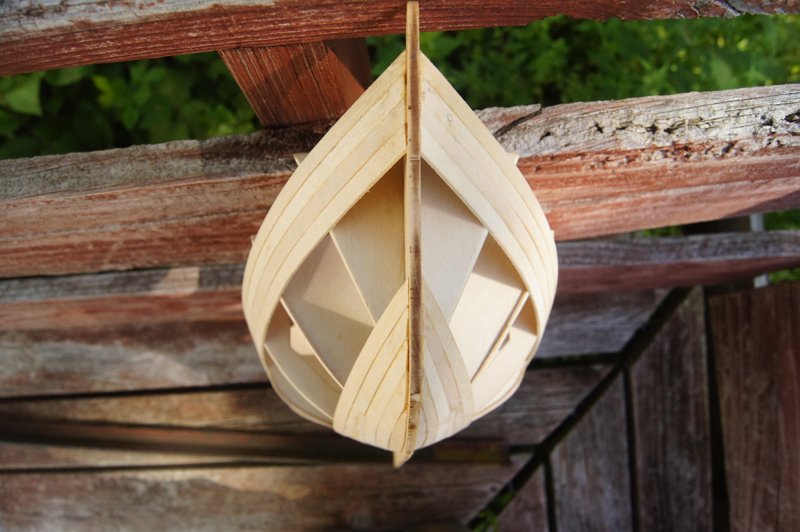
BlueJacket Shipcrafters seems to be under-represented in build logs on MSW, despite their reputation as a quality American model company that’s been in business a very long time. I recently completed their Lobster Boat kit and thought I’d write up a quick review, as there aren’t any build logs for this kit on MSW (I didn’t do a log myself as I wanted a break from documenting model work and intended this to be a relatively quick, relaxing build). Overall, I enjoyed building this kit, though there were a few things future builders might consider. Above is my finished model, built and named for my mother, who has long loved Maine, especially the Schoodic Peninsula. The number boards commemorate this year's birthday, when she'll receive this model. It's finished in the same green and white color as my current house. Positives: Good-quality materials. All the wood was solid and easy to work with, and the castings were clean and straightforward. Clear and accurate plans. These matched the kit’s parts and were helpful as a reference. I could have used them to scratchbuild this without the instructions or materials. Not too complicated. The kit might be tough for a complete beginner as it assumes a bit of knowledge, but almost anyone could figure these bits out and it’s pretty straightforward overall. It doesn’t have a lot of detail, which I think is good as it keeps the cost down and lets you choose whether you want to invest the time and money into creating a more detailed custom version. Concerns: The written instruction booklet is less than ideal. The black-and-white photos are very grainy and make it difficult to see any useful detail. For example, I was essentially unable to determine the planking pattern used because the photo was so blurry. Also, the text is presented in a long, linear block that could really use better organization and editing. Photos and drawings are often placed nowhere near their relevant text, resulting in lots of flipping back and forth trying to make sense of a given step. There is some "curse of knowledge" in places, where the instructions refer to a given part without defining what that is in real life or providing a clear diagram or label for the model. Bow design. The kit’s default is to use a large carved block at the bow, rather than planking all the way to the stem. With no experience, I had a very hard time carving and shaping this properly and finally gave up and reverted to planking the whole hull, something I have more experience in. That may just be my own problem, but it’s something a beginner should consider. Also, the added material needed to plank the whole hull (rather than just up to the bow block) meant that I exhausted the kit material and had to use a few pieces of my own scrap to complete the work. Beware of this potential if you decide to fully plank the hull rather than carving the bow. A few oddities in the proper fit and size of pieces. For example, several of the hull frames really didn’t line up with the others, requiring me to add a 1/8” strip along the frame to match the flow of the planking or to carve/sand away material. Some of the cabin pieces also needed significant sanding or additions to form up properly. None of this was particularly difficult, but did mean that builders should be careful to check everything before gluing. For example, see the following two photos: In the photo above, note that the run of lower planking really bows upward at the third frame from the stern. I somehow missed this when checking my fairing and planking run. It isn't really noticeable on the finished model because both the paint and position hide it from clear view, but this clearly needed extra material added to the frame. In the photo above, you can see the thickness of extra material I needed to add to both sides of the second frame from the bow to match the natural flow of the planks. It's more obvious on the right side due to the shadow effect, but it's the same for both. The fourth frame from the bow has similar material attached to widen it, while other frames needed to be sanded down by a similar margin. Getting a smooth run of planking was more work than I expected, though not particularly difficult. Here are two more photos of the completed model from various perspectives: Overall, I certainly recommend this model as a fun build. True beginners should be cautious and would benefit from carefully thinking through every step, test-fitting everything, and doing some research on the side to understand certain aspects of kit-building that are taken for granted by the instructions. Although I mildly criticize the instructions and a few parts above, they were still far better than those of the Corel Ranger that I built before this. Overall, the concerns were minor and easily dealt with by common sense and careful work, and the result is a quite attractive model (in my humble opinion). It has a lot of potential for adding extra detail if you really want a realistic appearance; for my mother, I was happy with a representative model that captures the feel of these iconic American work boats without much fuss. This was my first BlueJacket kit and I would definitely purchase another.
-
This is a fun kit that can be deceptively challenging (in a good way). I learned a lot from it and it looks like you're off to a good start.
-
Very nice work so far. I've never worked with PE before so it's interesting to see your progress and methods.
-
That seems like it would cause problems later on. I've always liked planking when I can turn the hull over and work on it; if there's more delicate structures on the deck, won't that make it harder to work on planking later? Or at least require the construction of a proper supporting rig to protect those structure?
-
Where can I downvote Corel on all counts?
-
Oops, you're right. I searched for O scale figures and didn't double-check that Google returned the right scale. HO is actually about half the size (hence Half-O scale), at 1:87, so those would actually be midgets. But here's an example that should work. Overall, your best best is still to search for model railroad figures with a western, old-time, or steam-era theme, making sure they're American or at least not blatantly European. The company I linked to there, Walthers, is about the biggest retailer of model railroad products in the US and a good starting point for a search. I have no idea if/how they ship overseas, but their catalogue will at least give you a sense of what's out there.
-
Chris, 1:50 is very close to the model railroad O scale (1:48), for which there are a variety of figures available. If you like for "old-time" or "western" style figures, you'll be in roughly the right time period (mid-late 1800s). Here's one example I found with a quick search. Just be careful about European brands like Preiser, their prototypes tend to be European and you could get some very strange uniforms and styles for a riverboat on the American frontier. As for color, I definitely feel that white is the correct choice. It was by far the most common color and thus will "feel" authentic. As you suggest, shoot for a thin coat of paint that lets the planking show through; it would have been visible on the real thing. You really can't go wrong with a white hull and superstructure, dull red/brown main deck and wheel(s), and dark grey/black tarpaper covering on the exposed upper decks.
-
Yeah, Way's is a lot of fun to browse, though a bit mind-blowing in its diversity and complexity. Once you've read through the logs Kurt suggested, I'd also suggest Glenn Grieco's Heroine and, humbly, my Bertrand (see link in signature).
-
Over lunch I skimmed through all my riverboat references and could not find a single reference to caulking or any other treatment of the seams between deck planking on American riverboats. Even the archeological report on the Bertrand didn't say anything about this, and they documented the location and dimensions of every single plank on the main deck. It's an interesting question. As Kurt notes, the only real threat would be rain, and most of the main and boiler deck areas were covered by higher decks eventually capped with tarpaper, such that the only real deck area clearly exposed to the weather without tarpaper or other covering would be the bow area and the outer edges of the main deck. The guards (if present) certainly wouldn't need caulking as they didn't cover any hull area. So my guess would be that caulking either wasn't used or was done only in the bow area of the main deck. On the other hand, given the potential intensity of rainstorms in the Mississippi Basin, a riverboat deck could easily be awash in minutes from driving, blowing rain, and many boats had open cargo areas on the main deck with minimal superstructure to block wind-driven rain. So it's not hard to imagine a thunderstorm dropping multiple inches of rain in short order that could blow/leak down into the hold, causing potential problems for cargo stored there. But my guess that this just wasn't enough of a problem to warrant caulking; a competent crew would simply not store any water-sensitive cargo far forward in the hull (the only place really potentially prone to meaningful leaks from above) or use basic tarpaulins as necessary. I'm interested to know what Kurt finds out from his sources.
-
size of people
Cathead replied to Snow's topic in Discussion for a Ship's Deck Furniture, Guns, boats and other Fittings
Well said, Imagna, it's not about laziness but about efficiency. Yes, if you only need one calculation, it's quite easy to do the math. But at the scale of a full build, there's nothing wrong with setting up a more efficient way to do the work. Or should we all hand-cut every bit of railing rather than using a stopper to automate the cuts? -
size of people
Cathead replied to Snow's topic in Discussion for a Ship's Deck Furniture, Guns, boats and other Fittings
As I mentioned earlier, I went ahead and wrote up a tutorial on using spreadsheets to calculate model conversions. This is exactly the kind of tool that would let you quickly figure out various measurements at 1/60 (such as a person's height) without having to remember and set up equations each time or search for the right online conversion tool. I mention it here at the risk of self-promotion because it seems pretty relevant. -
Hard to say for sure what's "accurate", but I agree that a sloped skylight set back from the edge a bit makes logical sense.
- 362 replies
-
- 2
-

-
- active
- revenue cutter
- (and 1 more)
-
I've learned to do it by hand (i.e. no power tools), either by taper square stock with a knife then sanding, or just sanding down a dowel. In fairness, the largest ship I've built is a topsail schooner, but doing it by hand makes sure I don't overdo it. I just put on an audio book or baseball game and work away.
-
Regarding cats, my avatar is getting on in years and has never been overly adventurous. As long as I push in the chair at the model desk, she doesn't try to get up there. Not sure how to exclude a more active cat other than a door. Hope you have fun with this model and manage to keep the paws off.
-
This is really cool; I love builds that help me learn about the ship itself. And I really appreciate the captioned photos that clearly document your steps. I'm going to try that angled plank end approach, too, seems obvious now that it's pointed out.
-
This is a really neat project. Being from the American Midwest, I had never heard of this type of kit before. It seems a very intelligent and interesting approach. Can you share any more about how this sort of thing works? In any case, being of partial German heritage and fascinated by this era as a kid, I'm excited to follow along on this.
-
size of people
Cathead replied to Snow's topic in Discussion for a Ship's Deck Furniture, Guns, boats and other Fittings
A good ruler is indeed invaluable. But you can also use any of the multitude of online conversion calculators available. For example, go to http://www.onlineconversion.com/length_common.htm and just enter 6 feet divided by mm, then divide that by 60. Pretty much every computer has a basic calculator you can do that last step on if you don't have a physical one. Or you can use a spreadsheet like Excel, and if you don't have that, you can use the free versions offered by platforms like Google. For every one of my builds, I set up a basic spreadsheet that has a number of common conversions for that model's scale, and a few custom fields that let me enter a given number and have it spit out the corresponding scale measurement. Maybe I should write up something about this with examples as a separate post. -
This is a someday build for me as I really like the look of Admiralty models. Your careful build looks great so far. I look forward to your progress.
-
Pretty much every model has workmanship flaws if you look close. Mine sure as heck do. Part of what I enjoyed so much about this one was your combination of freelanced accuracy; you created something of your own but still a very realistic representation of the type. Your words are kind, too, but I'd say Glenn Grieco was the biggest draw of interest before he had to give up the build log.
- 69 replies
-
- 1
-
-
- city of monroe
- steamboat
- (and 1 more)
-
That looks very similar to the mast arrangement and sail plan of the Bounty's launch. Technically a different style of boat, but it's your model, and there were almost certainly some unusual prototypical arrangements out there.
- 66 replies
-
- 2
-
-
- bounty launch
- model shipways
- (and 1 more)
-
Well, this is a wonderful model and I'm so glad you shared it with us. I devoutly hope I can produce such work 50 years from now (yes, I skew the age distribution here).
- 69 replies
-
- 1
-
-
- city of monroe
- steamboat
- (and 1 more)
-
SS Mariefred by captainbob - 1:96
Cathead replied to captainbob's topic in - Build logs for subjects built 1901 - Present Day
Thank you for sharing this news. I had been missing his updates on this model, and his presence in general, and now I know why.