


Cathead
-
Posts
3,530 -
Joined
-
Last visited
Content Type
Profiles
Forums
Gallery
Events
Everything posted by Cathead
-
 Roger, I'll look forward to your photo. After a bit more research, your explanation matches my new mental impression of how the transom is supposed to be; the filler blocks represent the lower/horizontal portion of the horn timbers, while the solid "transom" piece represents the upright framing that connects at an angle, just in a cheap and confusing way. The kit does have the stern extending out beyond the rudder post, which passes up between the filler blocks as it should, leaving the transom extending to the stern past the rudder, so I think that part is right (you can see this slot in the photo below). Here's a quick mockup of what I think the transom framing should look like. Just imagine the lower portion of this assembly mortising into the lower horn timbers extending away from the camera, into where the filler blocks are instead: This would then be planked over fore and after, I assume, with the aft planking extending in a gently rounded curve just a bit beyond the hull planking and the low bulwarks. I looked at a plan for a similar William Doughty vessel, and it showed a gently rounded transom extending just beyond the hull. The above is crude, and not glued into place or anything, just me test-fitting pieces and drawings to see if it feels right. What do you think?
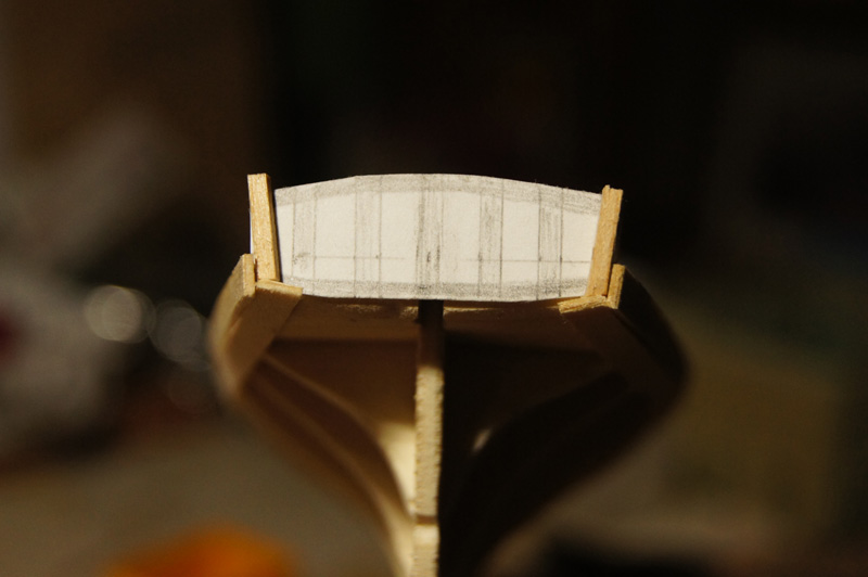
- 96 replies
-
- 7
-

-
- topsail schooner
- revenue cutter
- (and 3 more)
-
Roger, thank you for commenting. I'm afraid I can't quite see what you mean in that image, it's too blurry for my amateur eyes to pick out what you mean. Can you explain in more detail?
- 96 replies
-
- 4
-
-
- topsail schooner
- revenue cutter
- (and 3 more)
-
I agree with Roger; a dull, weathered red is ideal for the deck. I was very happy with my use of pastels to achieve this color without paint. Nice planking!
- 225 replies
-
- 3
-
-
- chaperon
- model shipways
- (and 1 more)
-
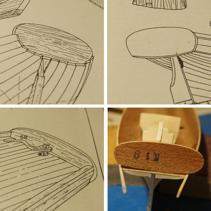
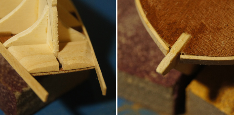
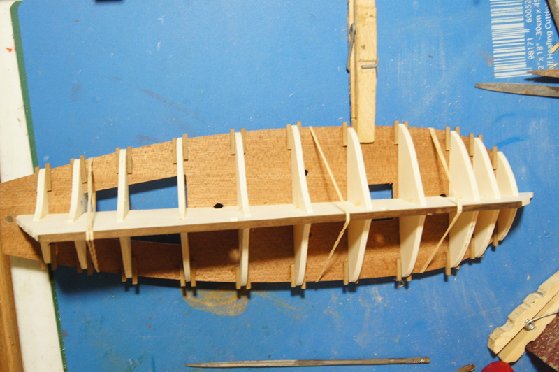
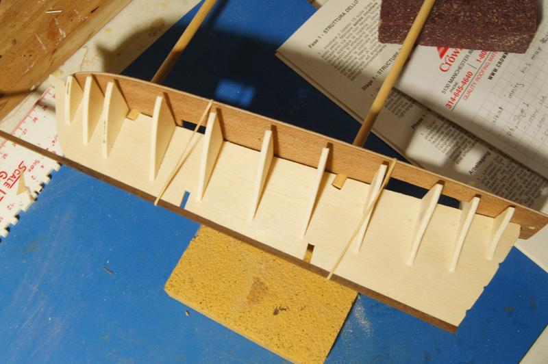
Stage 3 - preparation of frames for first planking Fairing the frames is pretty self-explanatory. I added thicker filler blocks at the bow and stern than those provided in the kit. The real challenge in this stage (and the next one) is deciding what to do about the transom. The instructions provide unclear, and conflicting, information about the transom's relationship to the planking. Just look at the images below: Upper left shows the first planking lining the outside of the transom. Upper right shows the second planking butting up against the inside of the transom, incompatible with the previous image. Lower left shows the planking butting up against the transom, too. The written directions don't help. The first plank (along the edge of the deck) is to be installed "terminating against the transoms", clearly contradicting the photo upper left. However, in Stage 4, they say of the first planking, "these are glued under the transom", implying that the photo upper left is what's intended. Adding to all this, the transom supplied in the kit appears way too wide (photo bottom right). Not only is it cut asymmetrically, it sticks out on either side well beyond the width of the hull, making it impossible to extend the planking along its side. Matt.s.s appeared to get around this problem by doing both; butting the first plank up against the transom while wrapping the rest around the outside. I'm honestly not sure what's accurate here; should the transom extend beyond the hull's width at all, or be fully contained within the planking? My instinct is to terminate all the planking against the transom, which makes life much easier. Stage 3 involves laying the first strake along the edge of the deck, so here it is. The edges pulled away from the bow a bit; I thought I had it clamped tightly enough when I left it, but now there's this annoying gap with stretched glue solidified in it. I'm trying to decide whether to attempt to re-do this or just not worry about it and allow the planking to flow from here, as this is just the first layer and I can fill and sand to my heart's desire before laying the final planking. Either way, it's on to Stage 4, planking the rest of the hull.
- 96 replies
-
- 8
-
-
- topsail schooner
- revenue cutter
- (and 3 more)
-
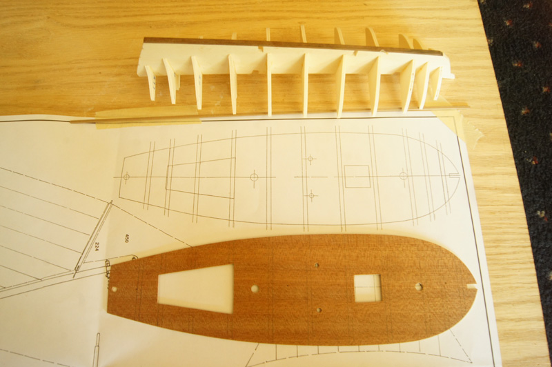
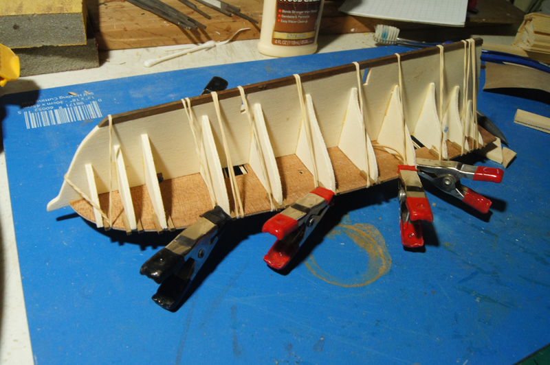
Stage 2 - Deck Now the deck needs to be fitted to the frames. I don't agree with the way the instructions approach this step, and will suggest an alternative. The plans show the theoretical location of each frame where it meets the deck (top of photo below). The instructions want you to glue a series of short walnut laths onto the deck's underside, on either side of where the frames will go, to provide a nice secure slot. This is sensible. However, the instructions tell you to do this by taping these laths to the plans, spreading glue on them, then carefully placing the deck over them and weighing it down. I though this approach sounded overly complicated and sure to create problems, so I used a different approach. As faintly shown in the photo above, I laid the deck over the plans and traced the outline of each frame's ideal position onto the deck. I then fit the deck onto the frames and compared theory with reality, adjusting my pencil lines where needed (a few didn't quite match up). If I'd done it the plans' way, I would have been very annoyed to discover my plans not quite fitting the walnut slots. Instead, I glued laths onto the deck individually, so I could position each one properly instead of relying on the decking sitting on them all perfectly. I did all the aft-side laths first; when they dried I test-fitted the deck again, held it on with a few rubber bands, and added the fore-side laths so they'd be snug against the actual frames (photo below). This worked beautifully for creating nice tight slots for the frames that fitted the actual model, not the ideal plan version which didn't quite match the cut parts. Alternatively, I could see an argument for gluing the laths onto the deck before gluing the frames to the keel, then using the pre-slotted deck to ensure that each frame is exactly where it's supposed to be. But if you glue in the frames first, don't pre-glue the laths on the deck without checking as described above. The kit isn't engineered well enough to take that gamble. When I was happy with the slots, I moved on to attaching the deck. The instructions suggest wetting the surface of the plywood, then spreading glue on the frames and bending/gluing the whole thing at once. I was suspicious of this, so wet the deck (using a toothbrush and water dish) and fit it first without glue, rubber-banding it down and letting it dry into the proper camber. Honestly, I didn't need to do this, the deck bent really nicely with a light surface wetting, but it didn't hurt either. Once it was dry and I was happy with the fit, I removed the deck, spread thin glue along all the frames, then re-wet and refit the deck. I wrapped rubber bands around the structure at every frame to ensure that the deck bent properly and fully through the camber. I'm pleased with the final result. The structure is strong and ready for the next step. Next up: fairing and filler blocks.
- 96 replies
-
- 7
-
-
- topsail schooner
- revenue cutter
- (and 3 more)
-
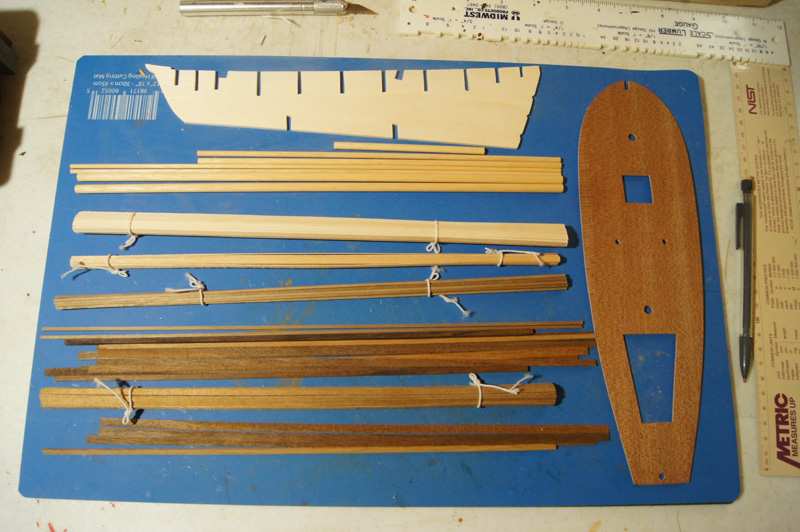
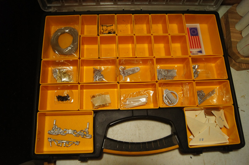
As there are few build logs for this kit, I'd like to make this one as useful as possible for others who might follow it later. So I'm going to attempt to match my posts to each stage of the instructions, offering my own interpretation of the intended work. I hope to provide a clear depiction of this kit's progress. First a quick look at the parts. The frames are pre-cut, unlike the laser-cut parts left in sheets that I've encountered in previous kits, meaning there isn't any spare material to work with if you break something. No parts list was provided, meaning I just have to hope everything is here. The wood seems of reasonable quality to my amateur eye. The fittings are bagged, but again with no parts list, so I'll just hope for the best. I have them all divided up into my handy organizer. Many of the castings seem coarse with a lot of flashing and other mess, and I'm going to be tempted to replace or rebuild many of them, but that's a later discussion. Stage 1 - Structure of the hull I glued the proper walnut lath onto the bottom of the keel. Each precut frame is numbered and corresponds to a numbered slot on the false keel. While the plywood seems nice and solid, the slots weren't cleanly cut and many needed significant filing to widen them enough to allow the parts to fit together properly. Once they all fit, I test-fit the plywood deck to ensure that everything seemed square. The instructions don't suggest this, but it's a good idea, as filing the slots wider can make some frames off-kilter without correction. Another suggestion: test-fit the masts through the deck into the holes in the keel; these holes don't line up quite right and some extra sanding needs to be done. It was much easier to do now than later. See photo above for testing of deck and masts with frames (note that the deck hasn't been bent into its final camber yet). Only when I was sure of everything did I glue the frames in place. Oh, one other note: carefully check the deck's fit over frames 8 and 10, which stick up through and beyond the deck to form walls of the small deckhouse. I found that I needed to file down the edges of these walls, at an angle, to match the angle of the deck's precut hole. Only by doing this could I get a proper fit. Next up: properly fitting the plywood deck.
- 96 replies
-
- 9
-
-
- topsail schooner
- revenue cutter
- (and 3 more)
-
For weathering, try using basic artists' pastels to gently rub on a coat of grey or light brown, which will dull any "shine" from the paint and bring out some wood texture. Has worked great for me for many years.
-
Model Expo 1/2 money back if built in a year??
Cathead replied to WEHarlow's topic in Wood ship model kits
I bought two models on that deal. It was definitely a credit. 50% off the list price at purchase, the other 50% as a credit toward anything they sold, without expiration. -
That structure does sit approximately where the boilers would be on a real vessel, so boiler room seems an appropriate label.
- 60 replies
-
- 2
-
-
- king of the mississippi
- artesania latina
- (and 1 more)
-
Steamboats and other rivercraft - general discussion
Cathead replied to Cathead's topic in Nautical/Naval History
Sal, That's a neat prototype, to be sure. Just to clarify, the placement of the paddle wheels isn't diagnostic of the boat's design or location. Western river boats used both stern and side wheel designs, as each has its benefits and drawbacks. Stern wheels were generally better for shallow or snag-filled water, as the hull protected the wheel, whereas side wheels were quite susceptible to damage being exposed on the sides. In addition, stern wheels could be used to help a boat cross shallow bars or back off muddy shorelines; setting the wheel in reverse forced lots of water under the hull, "floating" it off an obstacle. On the other hand, side wheels were more maneuverable, as they could be independently stopped or run in opposite directions, spinning the boat in place (at least on later designs with separate engines for each wheel). They also distributed the weight of machinery closer to the center of the vessel, reducing the "hogging" so common on stern wheel designs. For rivers like the Hudson, which were deep and tame compared to the western rivers, side wheelers made a lot more sense, so that's what you mostly see. This is also true of the lower Mississippi, below the confluence of the Missouri and Ohio rivers into the main stem. But you saw a lot more stern wheelers as you went upstream to the upper Ohio and Missouri rivers in particular, and their smaller tributaries. This is also the case because the western rivers, especially the Missouri, tended to have a lot of debris in them because their basins' geology wasn't as dominated by bedrock. Banks were always eroding away in huge chunks, dropping wads of trees into the river, and changing the rivers' courses regularly. By contrast, most eastern rivers like the Hudson are bedrock-dominated; they don't change course much at all and they don't erode their banks in the same way, so they tended to be "cleaner" of debris with more stable channels, negating the main benefits of stern wheel designs. So you tended to see side wheelers in the east, and a mix of the two in the West depending on where the boat's main work was intended to be (and various other factors, it's not quite this cut and dry). This is a broad overview, there are many per-river details that I could write a small book on. But hopefully that clarifies part of the question. Personally I don't have any resources to suggest about walking-beam engines, but hopefully someone else does. I've seen examples on craft from various parts of the world, so hope that someone else here can help you out. I hope you can find resources specific to eastern boats, as the designs and construction will be pretty different from the western boats, due to differences in materials, industrial capacity, design philosophy, and river conditions between the two regions. But the placement of the wheels, on its own, isn't a factor.- 281 replies
-
- 8
-
-
- Steamboats
- riverboats
- (and 3 more)
-
Thanks again to all of you. I've moved on to my next project, the Corel revenue cutter.
- 64 replies
-
- 3
-
-
- 18th century longboat
- model shipways
- (and 1 more)
-
Sorry, Glenn, I don't have any special insight. Any idea of Heroine used heat guards around the chimneys? You make a good point about consistently keeping it simple, rather than extrapolating beyond current knowledge. Part of my questions was when/how you're going to run the chimneys through the boiler deck. Will you make a separate assembly leading up to that deck, for ease of installation soon, then drop the rest of the chimneys in on top later on? Or will you make it all one assembly that you'll run through the boiler deck framing, and plank around later on?
-
Steamboats and other rivercraft - general discussion
Cathead replied to Cathead's topic in Nautical/Naval History
In this context, "western" means the river basins west of the Appalachian Mountains. When steamboat technology was developing in the early 19th century, this area (including the Ohio basin) was still the frontier, and nearly isolated from the developed part of the country along the Atlantic seaboard. Much of the design and technology that went into steamboat construction on the upper Ohio River, where almost all the boats used along the Mississippi, Missouri, and Ohio rivers (and their tributaries) were built, was fairly indigenous and not imported from elsewhere. This is especially true since conditions on these rivers were very different from most rivers draining east into the Atlantic. So we talk about "western river boats" to mean the unique set of designs and construction methods that arose in that region, distinguishing these craft from the very different boats built for eastern rivers like the Hudson. Even as late as the Civil War, this region was still considered the "West"; it wasn't until the development of railroads that the Mississippi basin really became integrated into the rest of the country. It gets a bit messier once you go west of the Rockies, to boats operating on the Columbia and other Pacific rivers. But as far as I know, these mostly derived their designs from the original "western" boats and so still qualify as such.- 281 replies
-
- 6
-
-
- Steamboats
- riverboats
- (and 3 more)
-
Steamboats and other rivercraft - general discussion
Cathead replied to Cathead's topic in Nautical/Naval History
Roger, do you know if similar designs evolved along the Missouri, where conditions were quite different, and even harsher, than on the Ohio? Given that most Missouri River boats were built along the upper Ohio, it's certainly logical that the design you describe was supplied to boats destined for the Missouri, but I could also see a new subdesign developing in that basin to meet unique local conditions. I've never thought much about this aspect of Western River steamboats before, and appreciate you bringing it up.- 281 replies
-
- 2
-
-
- Steamboats
- riverboats
- (and 3 more)
-
Speaking from my own knowledge, many riverboats used a dark red paint on their lower decks, wheels, etc. And white is very definitely accurate. Though for true correctness you might stain the lower bit muddy!
- 225 replies
-
- 3
-
-
- chaperon
- model shipways
- (and 1 more)
-
Mike, I agree with Chuck, and heck I could send you the plans I used for my Far West, as I don't need them anymore. Anyway, great start, keep it up!
- 225 replies
-
- 2
-
-
- chaperon
- model shipways
- (and 1 more)
-
(Image via Model-Expo, from whom I bought the kit). This kit is meant to represent one of many ships built in the early nineteenth century for the US Revenue Marine (fore-runner of today’s Coast Guard). However, no “Ranger” was ever built for that service during this time period, so the model only approximates a real prototype. The closest real vessels, according to my research, seem to be the two Alabama-class topsail schooners built in 1819 (Alabama and Louisiana). This conclusion is based on several factors: Recommendation of the Coast Guard Modeling website Comparison to plans available from the USCG website Dimensions given by USCG fact sheet for USRC Louisiana My own calculations. The resources above list the Alabama-class cutters as having a 52’ keel and 18’-6” beam, while Wikipedia also lists a length on deck of 56’-10”. The table below shows the kit’s measurements (taken from the plans), the kit’s size at full scale converted to feet, the actual dimensions from the sources above in feet, and the difference between the two scaled back down to kit size, in cm. Deck: kit(cm) 28, kit(feet) 62.6, real (feet) 57.0, diffrence (cm) 2.5 Beam: kit(cm) 9, kit(feet) 20.1, real (feet) 18.5, diffrence (cm) 0.7 Keel: kit(cm) 22.5, kit(feet) 50.2, real (feet) 52.0, diffrence (cm) -0.8 The kit does not perfectly match the Alabama-class cutters, most notably in deck length, but it’s closer to those than the other options (the 56’ Surprise class or the 60’ Search class). At this scale, only a true historian of the Revenue Marine will notice that the model is a few centimeters off; as I intend to build it as a fictional ship rather than as Alabama or Louisiana, this will matter even less. The overall hull shape, sail plan, and deck layout seem reasonably similar, and I will probably use the USCG drawing of Louisiana as a guide when the kit plans are uncertain or I prefer the former’s appearance. For example, the USCG drawing shows two swivel-based carronades of different calibers, which I find intriguing, and overall it’s more crisply drawn than the poor-quality photocopy in the kit. I could only find a few previous build logs for this kit, which are listed here for future reference (if I’ve missed one, please inform me): Ranger by matt s.s.: heavy kit-bash of the model into a glorious pirate ship. Ranger by trippwj: unfinished log, not updated since 2014, progress as far as beginning planking; intended to follow plans for the larger Search class vessels. Ranger by Small Stuff: unfinished log, not updated since 2014, many photos missing, progress as far as bulkheads. Ranger by Woodmiester12: unfinished log, not updated since 2015, progress as far as first hull & deck planking. So it looks like I’ll embarking on a fairly new adventure here, the most challenging model I’ve tackled to date, especially with the rather poor instructions in hideous English translation. Some may ask why I’m attempting this somewhat problematic kit when BlueJacket just released what is, by all accounts, a high quality kit of a similar revenue cutter. The answer is quite simple: I purchased this kit before learning of the BlueJacket release. Both I and Mrs Cathead love the look of topsail schooners, and I thought the challenge of working with a foreign kit would be good for developing my skills. Now that I’ve bought it, I’m going to build it. And for those of you wondering why I’m not tackling another steamboat, there is a twofold answer: one, the previous sentence, and two, it’s going to take me significant time to do the research and design necessary for a new scratchbuild. I’d like to do something that doesn’t have plans, like the Missouri River sidewheeler Arabia, and that’s a long-term project. So I’ll work on this revenue cutter in the meantime to keep my hands busy and my skills developing, and work on my steamboat plans in the background.
- 96 replies
-
- 9
-
-
- topsail schooner
- revenue cutter
- (and 3 more)
-
This is great. I've gone through and renamed my logs.
-
Those windows...I'll need to wipe the drool from my keyboard. What's your plan for running the chimneys through the boiler deck?
-
Mike, I'm not sure what it means to be a "friend" in this system but it sounds benign enough! For reference, this site is where I ordered plans for the Far West. I'm sure Kurt, Roger, and others will be quite helpful if and when you want to start looking at ideas. In the meantime, sorry for contributing to the takeover of your log, and look forward to the resumption of the topic at hand.
- 225 replies
-
- 2
-
-
- chaperon
- model shipways
- (and 1 more)
-
I'll follow along, and wish you much enjoyment from the project!
-
While I've never handled the AL kit, to my eye it looks toylike; out of scale and inaccurate. An attractive model can be made from it, just not a realistic one. So it depends on what you want. If you're really into realistic steamboats, there are a number of craft with good plans available that you could scratchbuild. From what I've seen, your skills are more than enough for that undertaking.
- 225 replies
-
- 2
-
-
- chaperon
- model shipways
- (and 1 more)
-
Kurt & Roger, Any insights into the whaleboat-like craft shown in the final photo, which as Kurt noted is more similar to the kit boats? I didn't know anything like that was used on the rivers, I assumed everything had a flat transom like a regular rowboat. The photo boat seems shallower draft than the kit boats, too, unless I'm seeing it wrong. Mike, thanks, but I'm an amateur compared to Kurt and others. I can't wait to learn more about this from you and the rest.
- 225 replies
-
- 3
-
-
- chaperon
- model shipways
- (and 1 more)
-
Cool, can't wait to see what you do with her. Thanks for the kind words.
