HOLIDAY DONATION DRIVE - SUPPORT MSW - DO YOUR PART TO KEEP THIS GREAT FORUM GOING! (Only 13 donations so far - C'mon guys!)
×


BenF89
-
Posts
316 -
Joined
-
Last visited
Content Type
Profiles
Forums
Gallery
Events
Everything posted by BenF89
-
 I like the method of using pre-colored wood for your planking above and below waterline - seems like painting that small would be a lot of extra time and trouble. Looking really good! And, you're a pilot? (My question comes from your comment about not having good flying weather....)
- 154 replies
-
- 1
-

-
- colin archer
- lifeboat
- (and 2 more)
-
I concur with Mark, Bob, and Patrick. As an engineer myself, I know the value of documenting failures - otherwise, we'd all keep doing the same dumb things, like flying DC-10's or neglecting eddy vortices when building bridges in windy straits (Tacoma Narrows...which, incidentally, I drive over every day to get to and from work, so I'm especially glad they figured that one out.) There's actually a very good book all about the important role failure plays in design, called 'To Engineer is Human' - I'd highly recommend it even if you have a layman's interest in design and engineering. Judging by the thought and quality going into this build, you've got more than a layman's interest, though! Ok, I'll get off my soap box now.
-
I echo Bob's sentiment! I try to catch a log before it's already over with, but here you are planking your already formed hull! Very impressive. Looking forward to following the rest. ~Ben
- 154 replies
-
- 1
-
-
- colin archer
- lifeboat
- (and 2 more)
-
Kees, Just stumbled upon this log - and I'm really bummed I only just caught the tail end! You've made a really impressive ship - it captures the essence of a workboat wonderfully! ~Ben
-
I'm in too! Looking forward to following this build. It's a good looking ship! But, I have a knack for modern workboats and the like. It's a reminder that the marine industry is still alive, and that there's still a lot of variety. They don't have the same type of charm as the old wooden ships and the like, but they have their own charm - and their own challenges in building! Again, really looking forward to it!
- 434 replies
-
- 2
-
-
- pelikaan
- beamtrawler
- (and 2 more)
-
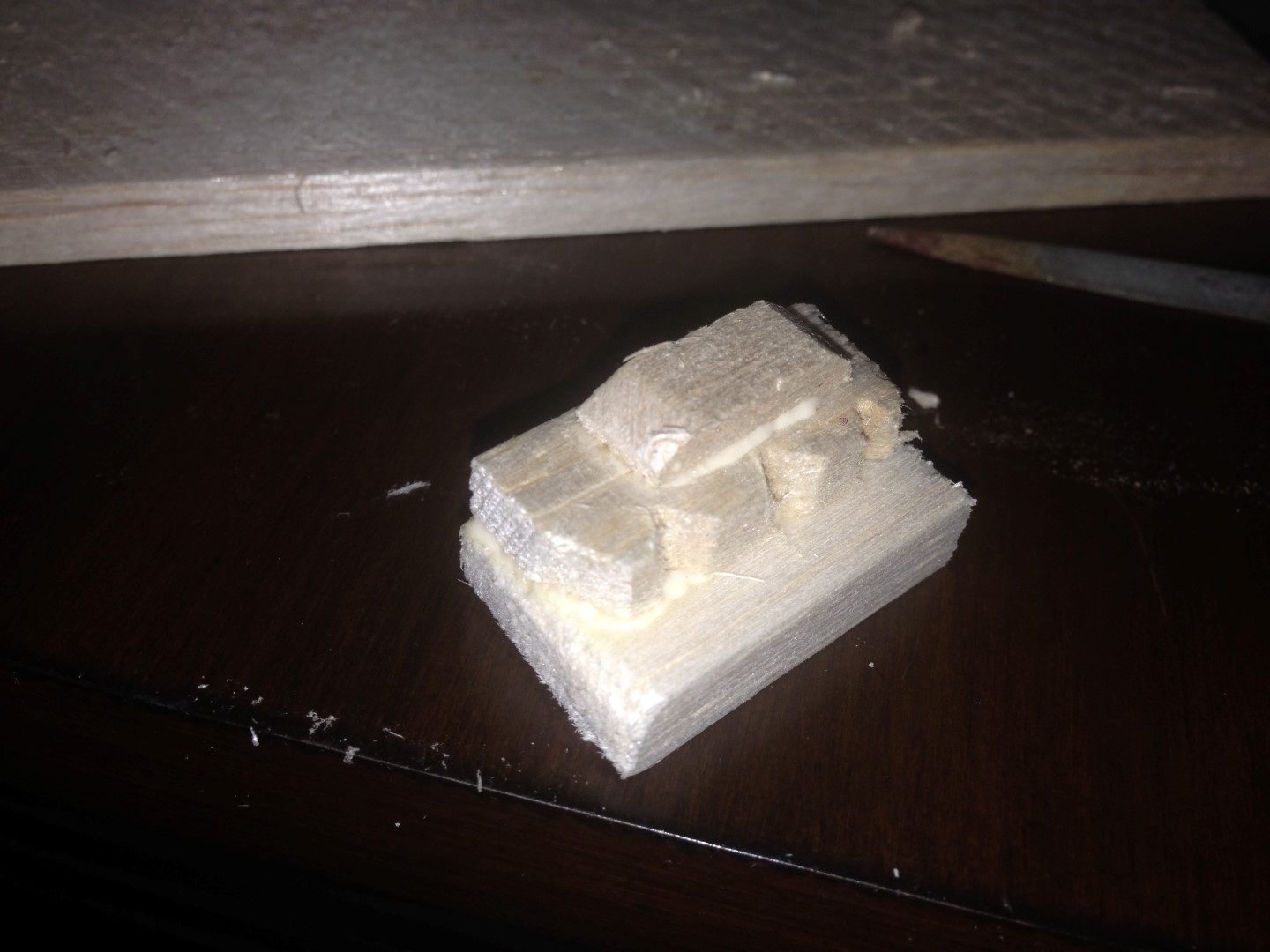
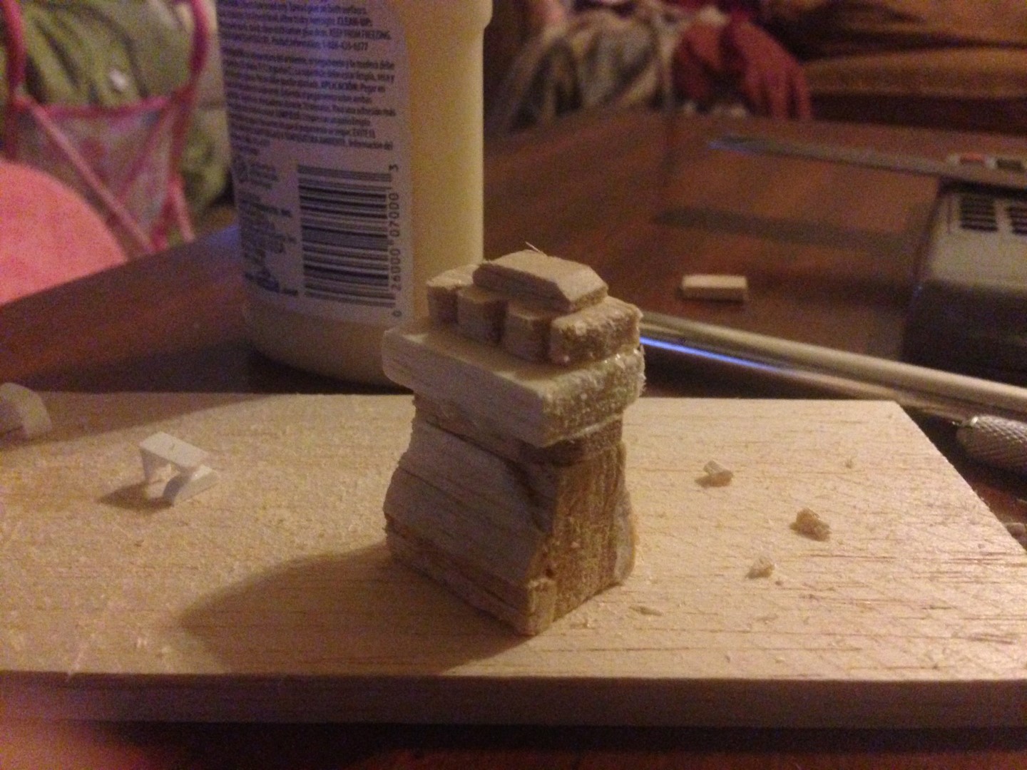
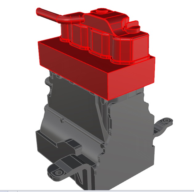
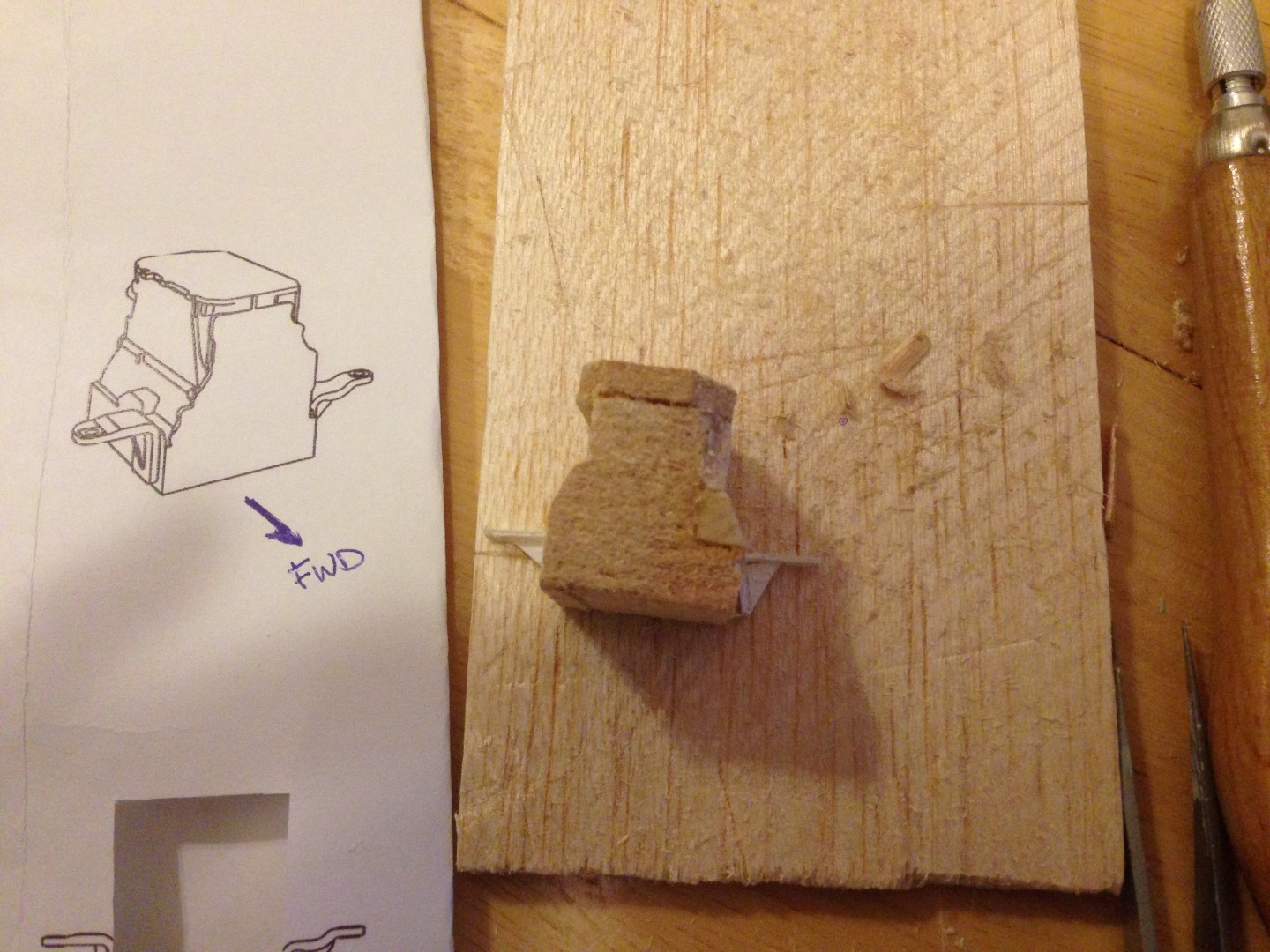
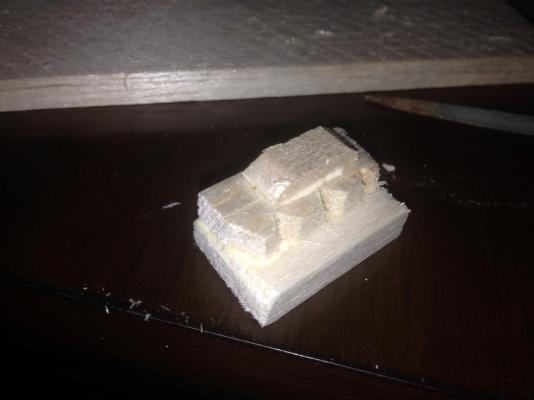
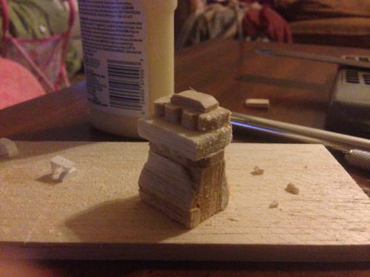
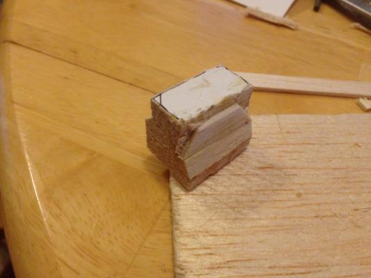
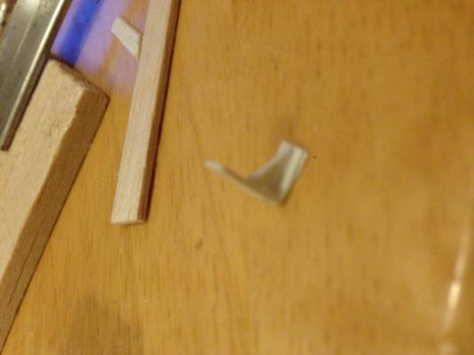
Mark, Thanks for the advice - I will try that! Patrick, Yes - an engine too! Go big or go home, right? If you can squeeze an engine into the Mystic at that small a scale, I can surely pull off SOMETHING like an engine at a 1:12 scale. My plan is to make the doll boat as lifelike as possible, including a lift-up companion way, and pull off side panels, to the engine compartment. And what would be an engine compartment with no engine?! CYLINDERS AND CYLINDER HEADS I got my wish last night- I was able to make the cylinder, cylinder heads, and rocker arm cover, and add it to the block. This one was easiest to make with three separate pieces. Cylinder Block and Cylinder Heads (In Red) The first was an easy warm up - a rectangle! I mostly just had to pull one of the sizes of the odds-and-ends balsa out of my grab bag, and cut it to length. Cylinder Block Then I had to make what appear to be the cylinder heads/valve covers. These were trickier, since they have a bit of shape to them. I ended up making two - I rushed/didn't use the right tooling the first time, and ended up taking chunks out of the wood. The second time fared better, so I added it to the cylinder block. Cylinder Block with Cylinder Heads The last piece was what looks like the rocker arm cover. This was another easy one - a small rectangle with beveled edges. I cut it, filed the edges, and added it to the assembly. Complete Cylinder Block/Head/Cover Assembly Then I added the whole assembly to the engine block. Pretty happy with how it looks thus far. Engine Assembly - to date. Whenever I get my next opportunity for progress, I think I will add the lube oil sump at the bottom of the engine, and potentially the flywheel cover.


-
Patrick, You're following in the footsteps of old school naval architects and shipwrights. Your method not only makes sense, its a tried and true method for doing exactly what you want to accomplish! The main entry hall of the college I attended was lined with half hulls of all different ships, designed by the founder of the school and used for the purpose of lofting fair lines for making frames. And, you look off to an excellent start. Keep on keepin' on!
-
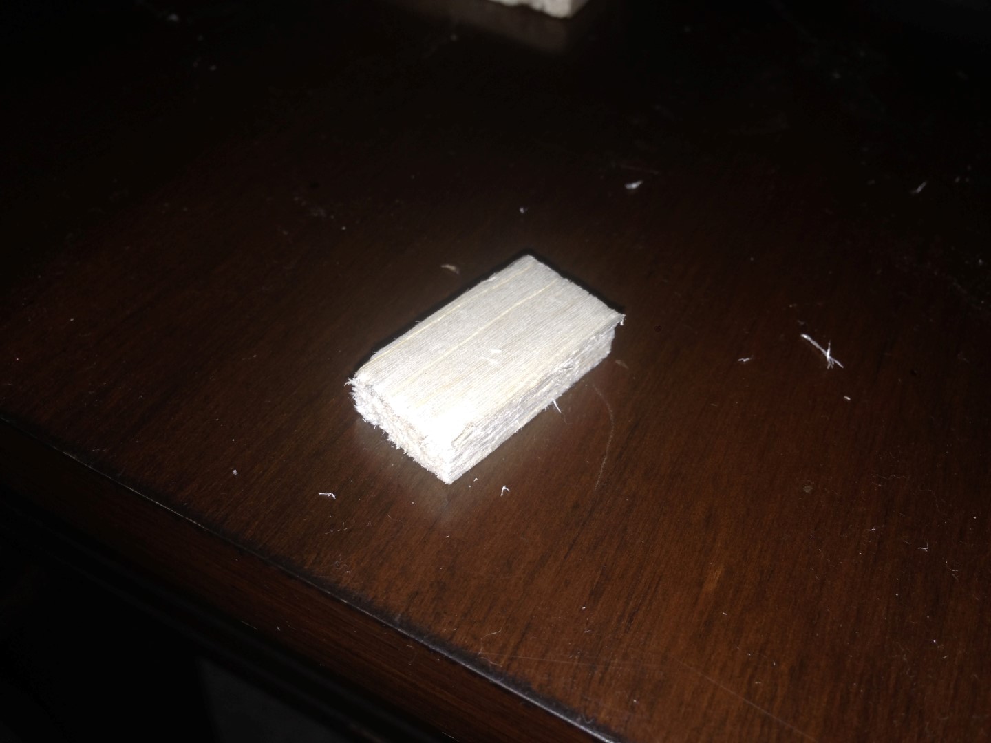
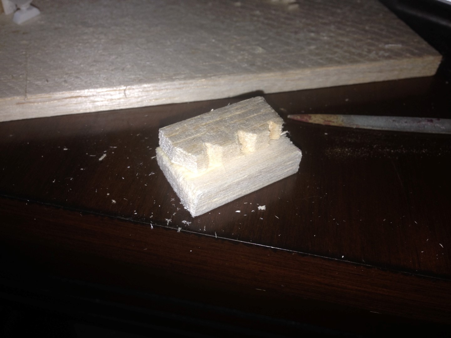
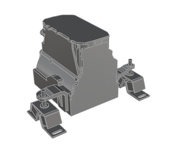
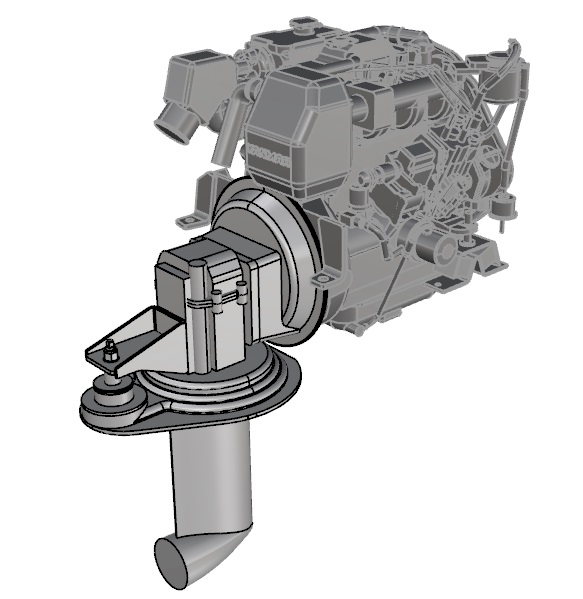
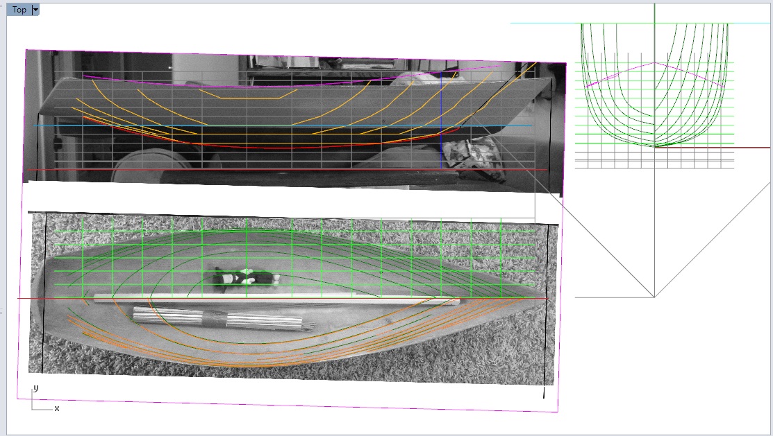
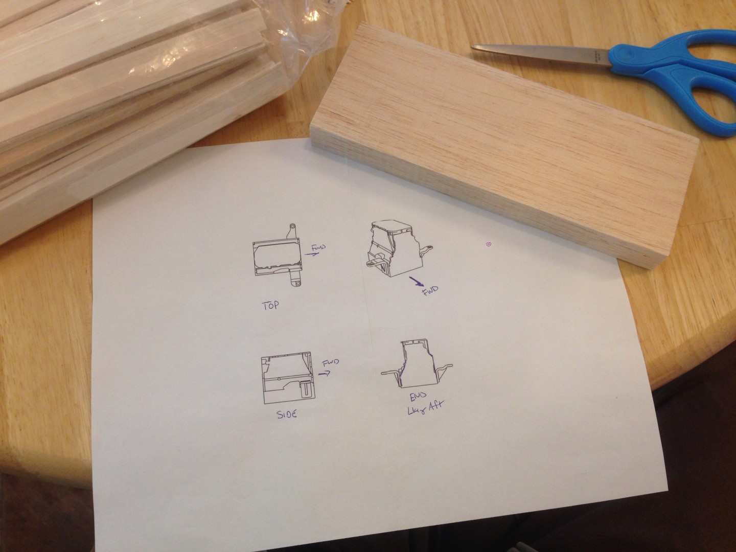
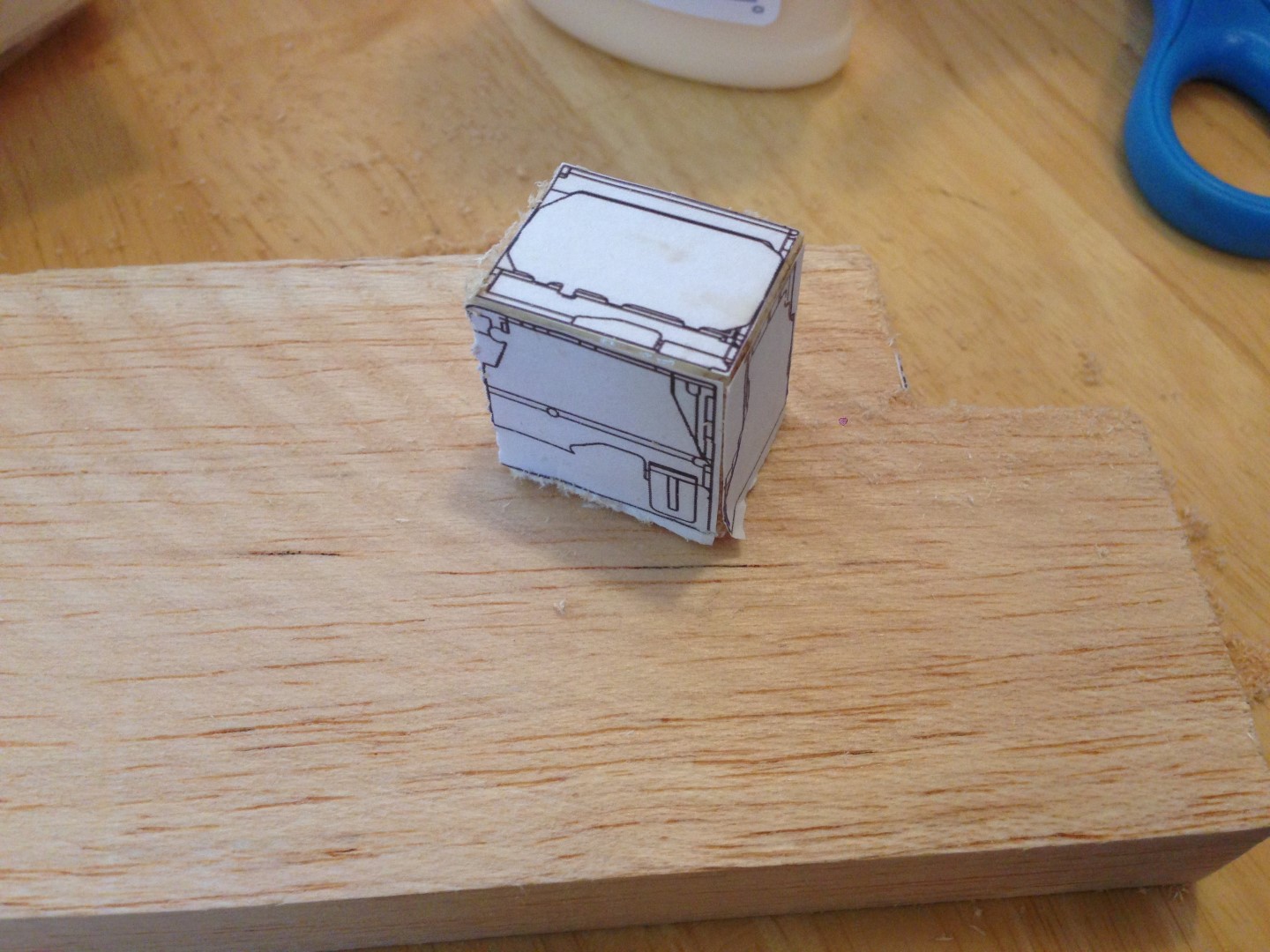
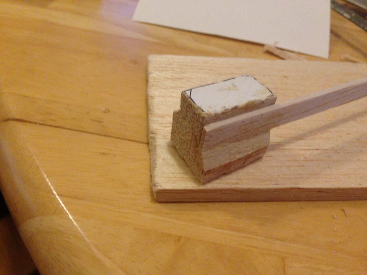
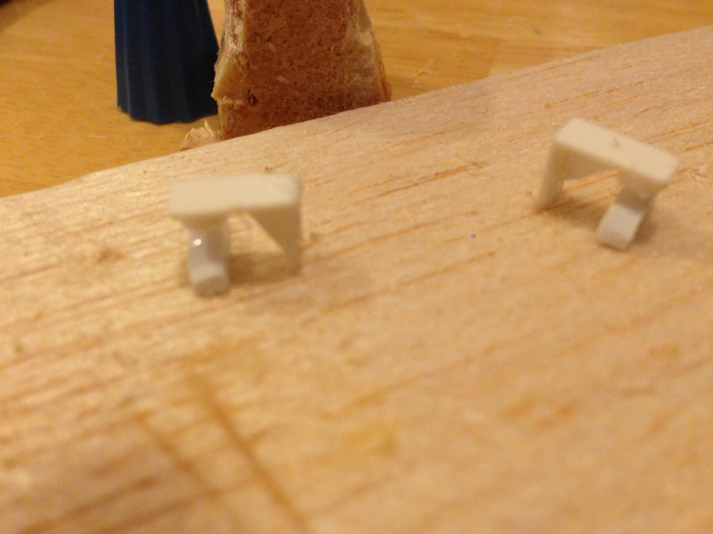
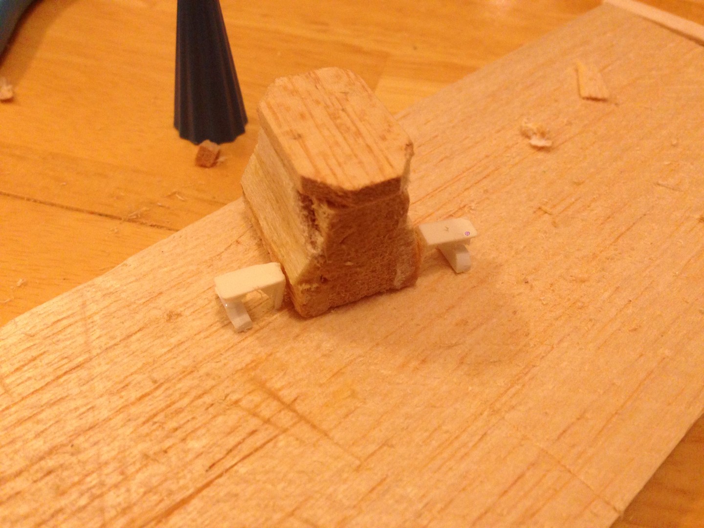
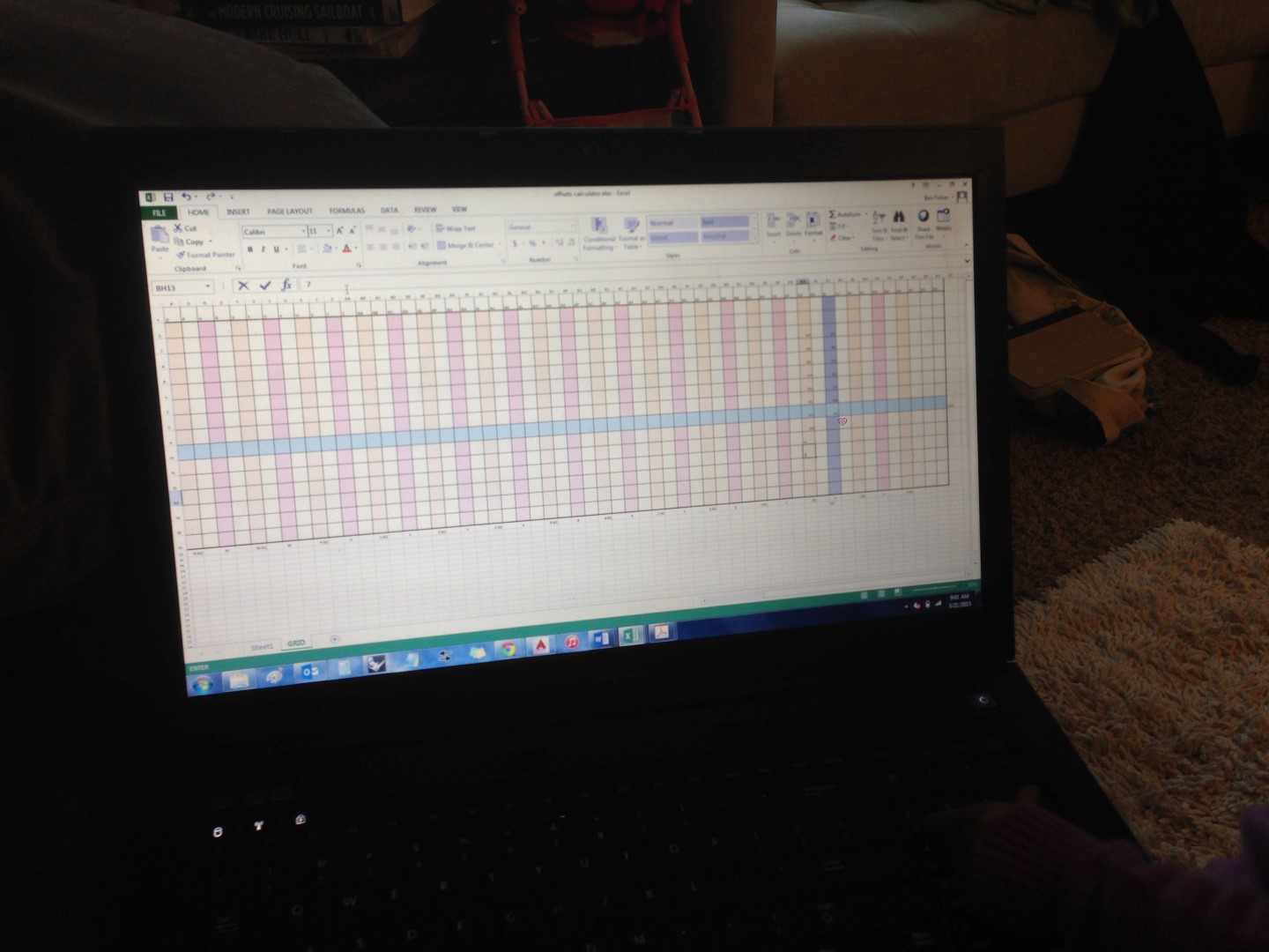
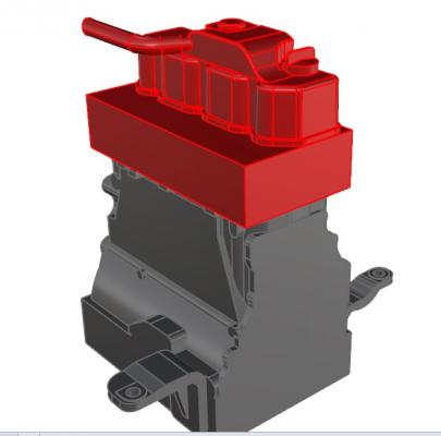
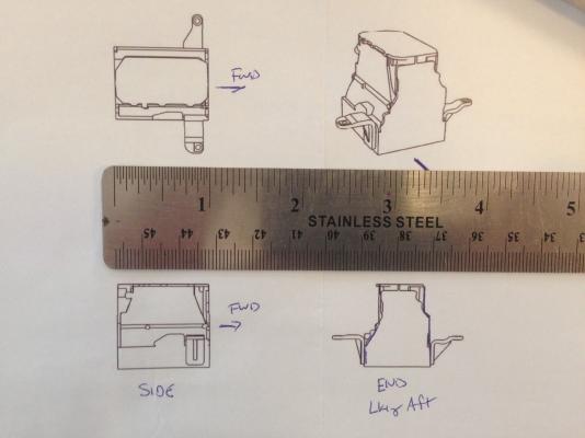
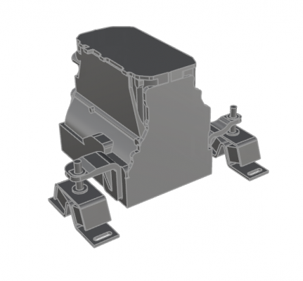
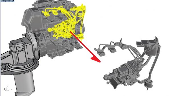
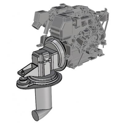
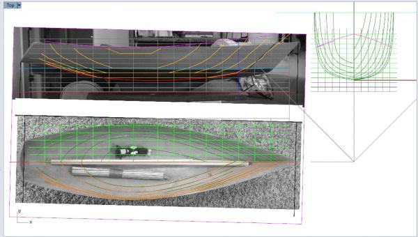
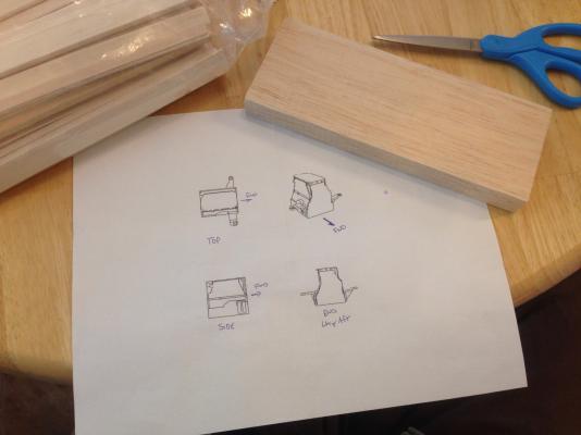
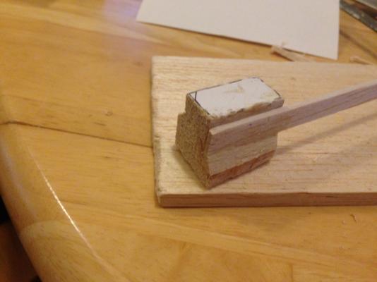
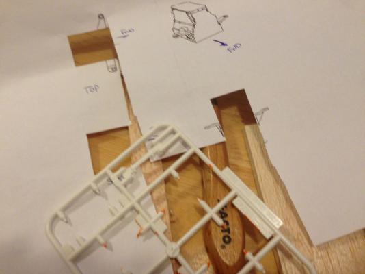
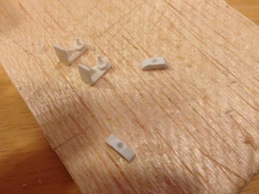
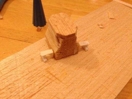
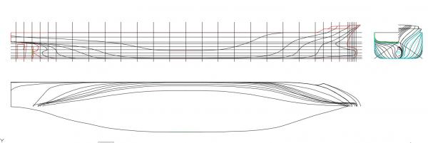
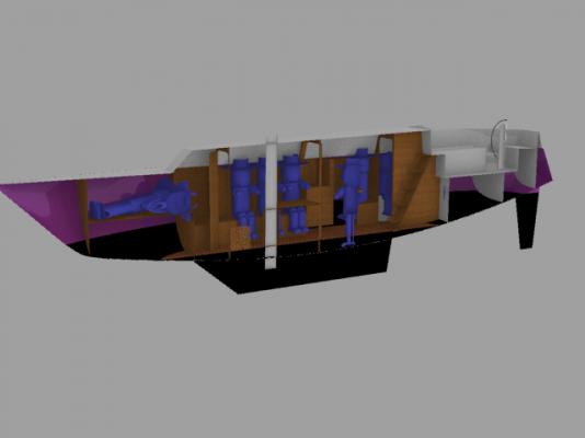
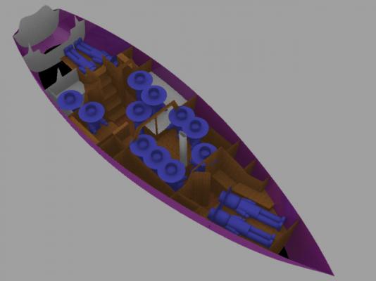
HULL LINES UPDATE (A.K.A Just Keep Fairing, Just Keep Fairing, Just Keep Fairing Fairing Fairing, What Do We Do - We FAIR!)* *Parody of Dory's 'Just Keep Swimming' song from Finding Nemo for those unfamiliar with the reference... Well, I made more progress with the lines, but I've run into some hiccups. The lines are getting fairer, but the hull I have in CAD is not the hull I have sitting in my spare room. The 'form' is close, but I've botched something up with (I think) the grid. It's either too short in length or too tall in height, and so when I lay my profile plan over a profile picture of the boat, it just doesn't match. I initially thought it was height, but laying in a plan view, it may actually be a length issue. See screen shot below. I just ....don't know. ¯\(°_o)/¯ So, I've been frustrated, and decided to take a break from lines and do something else, for fear of getting so bogged down with this issue that I just throw in the towel (my knee-jerk tendency). My remedy was to select, and then start researching a build process for, the auxiliary diesel for the sailboat. ENGINE SELECTION I had already done preliminary engine selection when I first started laying out concepts. However, I never went back through the spiral when I changed scale to 1:12. To do that, I basically opened up one of the books I have, made an Excel spreadsheet (which is essentially an engineer's first reflex when solving any problem ), and listed out all the boats in the 38-42 ft range, along with their installed power. I 'weeded' racing boats and cruiser-racers, to focus on cruising boats only. Then averaged the lengths and installed power. Based on that, I selected for this boat's auxiliary diesel a 38 HP Yanmar 3JH5E w/SD-60 saildrive. I selected this specific model for two reasons: 1 - it fit in the boat (very important consideration....) and 2 - Yanmar's website had a downloadable 3D model of the engine. (unfortunately, they didn't have a model of the saildrive unit, so I had to generate that myself using their ok-ish drawings. 3D Model of Engine (from Yanmar's site) and Saildrive Gear/Strut (developed by me from drawings) I've broken the models up into system-based chunks (e.g. - main engine block; fuel system; raw water supply; etc.). An example of just one of the systems isolated is below: Example System grouping - Fuel System Each system grouping is further broken down into smaller chunks - for the fuel system, the injectors are a chunk, the injection lines are a chunk, the injection pump is a chunk (with even smaller components itself, since it's pretty complex), etc. In this way, I can plan the build of the engine in chunks, starting with the block, and working to the insanity that is the fuel injection system. This leads me to... FIRST WOOD CUTTING! With all the problems I was running into with the lines, as I mentioned I was getting discouraged - mostly because I just wanted to build something! So I started with the engine block. Iso View of Block and Mounts I scaled the part, and printed it 1:1 so I could glue it directly to my piece of balsa wood. 1:1 Printout of Engine Block Prior to scaling and printing, I bought a grab-bag of balsa wood from a craft store for something like $10, which was awesome since it had a big range of sizes and types - square stock, planks, slabs. It just so happened that I had one slab 3/4" thick, which was PERFECT, since that was the width of the block. Printout with Balsa Slab I glued the printout on, and cut the first part! Hooray!! First Part Cut! The first owner's inspection went satisfactorily as well First Owner's Inspection From that first piece of wood, I then carved out the shape of the block, adding in some additional details using other pieces of wood as appropriate. Engine Block - shaped Once I completed the block proper, I still had some time left last evening, so I decided to make the mounts and mount bracket. Given that I've never really done any scratch building, I was fully prepared to have to make a second (or third) attempt. The first issue was even what to make them from (at scale, the wood was just too thick). Enter my hoarder tendencies! I had some old plastic model kit sprue lying around, and an initial inspection identified that the label plate for the sprue was the right width, and appeared to be appropriate thickness. Sprue used for Engine Mounts A bit of cutting and fiddling later, with a fair amount of - clean - negative exclamation, I had engine mounts!! I used the sprue label for the bracket, some small polystyrene tube for the boss plate on the bottom of the brackets, some 0.035" diameter rod for the stud, and some 0.100"x0.100" polystyrene square stock filed to shape for the mounting feet. Then I glued it all together...then dropped the parts, then they fell apart, then my tweezers got stuck to them, then (and on, and on). But - I eventually got a set of two engine mounts! Woohoo! First Mounting Bracket Both Mounting Brackets and Engine Block Boss Plates and Studs Added to Brackets; Mounting Feet Made Mounts Completed Completed Mounts Next to Block So now my next problem is figuring out how to bond the plastic to the wood. I tried a couple super glues, but my suspicion is that the balsa is too porous, and so the adhesive just soaks into it. I was thinking that some method of sealing the wood first (a coat of wood glue, or a thicker super glue, like Gorilla glue or other gap filling super glue, may do the trick.) Anyone have experience trying to do this? Any recommendations? Tonight I am going to start on the cylinder and cylinder head block, since it's another fairly blocky, easy to form piece, and it's the logical next step since it mounts to the top of the block.


-
Hi Patrick, Really looking forward to following another miniature adventure! You certainly have an eye for picking very attractive boats as your modeling subjects - and you've done them all justice so far. Excited to see this one as well. And, I actually much prefer the name 'Symphony' to any of the others. It has a musical ring to it ~Ben
-
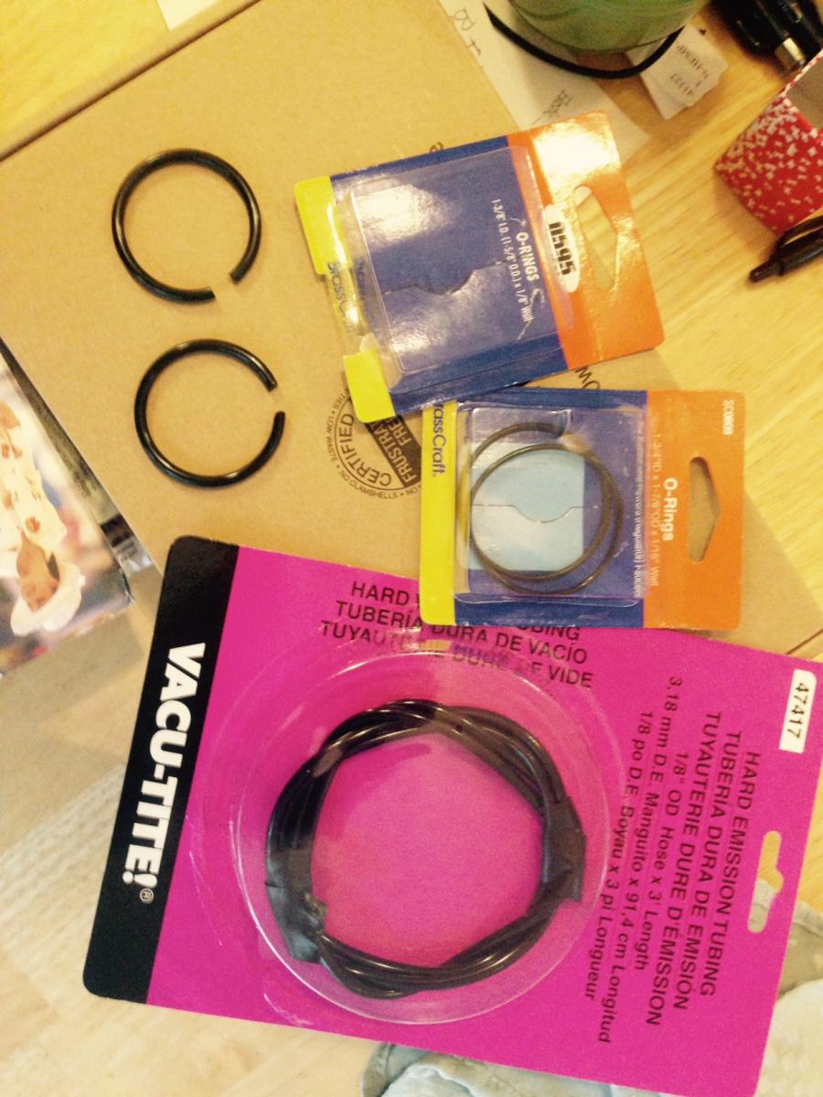
PLUMBING O-RINGS / AUTOMOTIVE VACUUM TUBING This may apply to more modern vessels, but they can be used to simulate rubber hoses for machinery. Cut the ring, and then cut to length as needed and bend to the shape needed. I got the O-Rings for less than a dollar per pack of 2 at a local installment of a national chain hardware store, and the vacuum hose at my local auto parts store for $5. I suspect they could be found cheaper online/elsewhere (esp the vacuum hose - but I was there and it caught my eye). I'm specifically intending to use them in my doll-boat project to help detail the sailboat's engine/ engine compartment. There are some big coolant and raw seawater hoses (vacuum tube/thicker O-rings), as well as some smaller diameter fuel hoses, etc (thinner O-rings). (Could be any scale; I'm working in 1:12)

- 396 replies
-
- 9
-
-
- Idea
- Bright Idea
- (and 1 more)
-
Long time reader, first time commenter Chiming in to say, first and foremost, this is one of my favorite builds to follow. There is something about modern workboats as model subjects that really excites me (probably because they are the types of things I would like to help design one day). Second, I can confirm that IRL does indeed mean 'In Real Life.' And finally, I share the sentiment that I'm torn between wanting to see the finished product, and not wanting the updates to stop! Keep up the good work - the quality is a goal for a newbie like me to aspire to.
- 956 replies
-
- 5
-
-
- andrea gail
- trawler
- (and 1 more)
-
The software makes things easier in some ways, definitely. For example, the lines can be tweaked with control points, vs. erased and redrawn. I suspect the real issue is that I am currently distanced enough (over 7 years....GAH!) from that first hand-drawn lines that I remember all the charm and none of the fact that the 'charm' was overshadowed by drawing and erasing lines at 3 am to get the project done before the deadline! As for my next project, alas, I already have a kit of the Edmund Fitzgerald sitting on my bookshelf. My wife has already informed me in no ambiguous terms that I can't start any more projects until I finish this boat and the Fitz! (I get told this all the time as ideas pop up) I see a kindred spirit in Popeye (Dennis) as I've been following his Andrea Gail build and how he mentions his other incomplete projects and new crazy ideas. Although, I can say I've already finished my Titanic model . My eventual goal is to make an RC Scratch Built model work boat or merchant ship of some sort. What exactly it will be when I ever get to that point remains to be seen. I may even make an RC scale model of the real boat I've been working on professionally. It would be an easy hull form - planing monohull with mostly geometric faces rather than sweeping curves. The propulsion would be the interesting challenge - it's waterjet driven. There are certainly working model waterjets out there, but they don't LOOK like the ones on the boat, and since they are a prominent feature of the transom, that's a problem to overcome.... But I've digressed far off the current path at this point. Anything to avoid fairing lines, I suppose
-
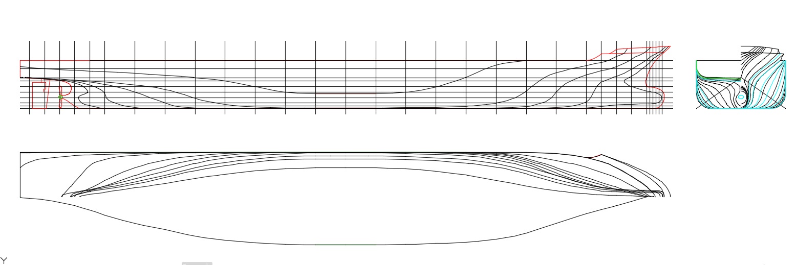
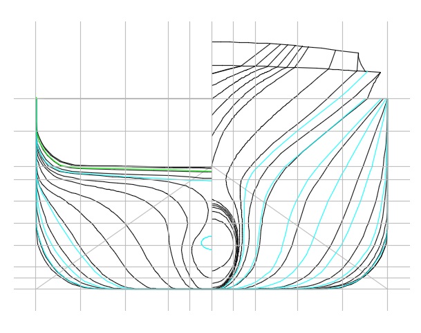
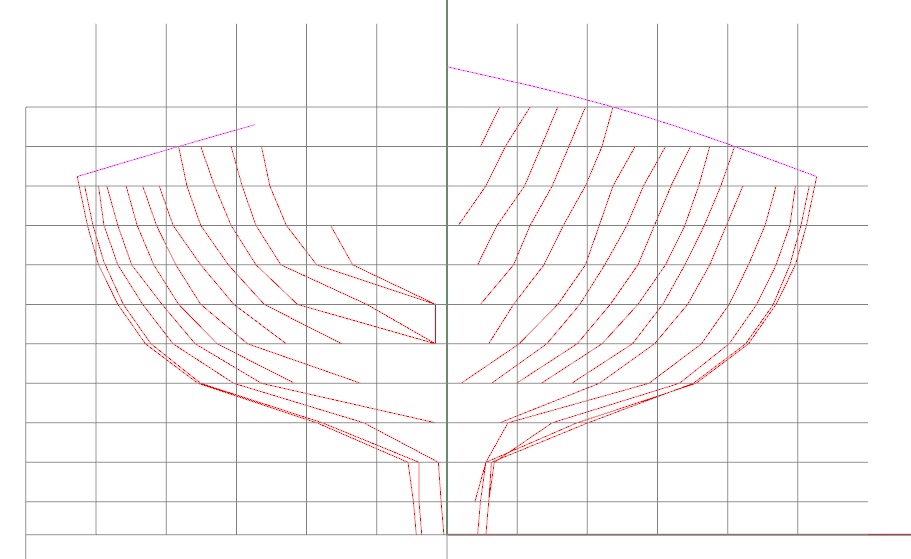
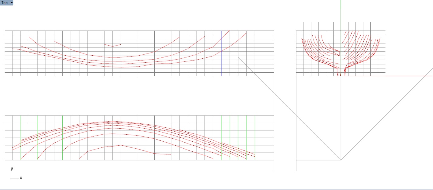
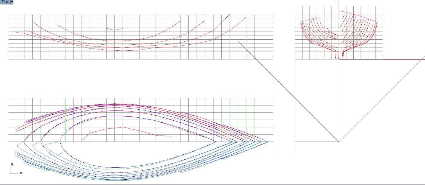
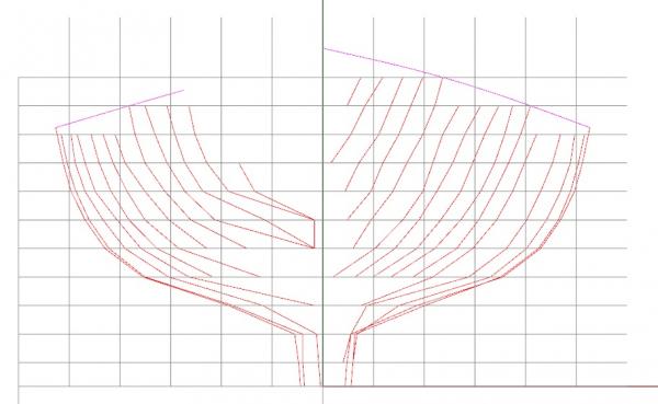
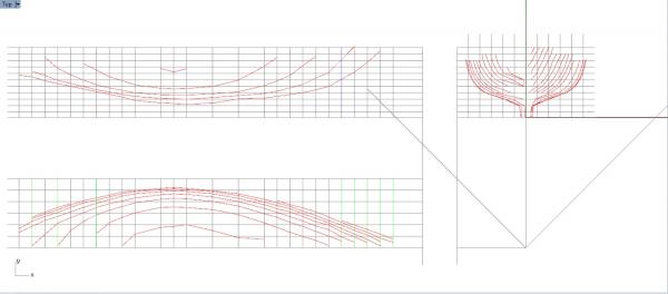
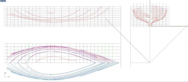
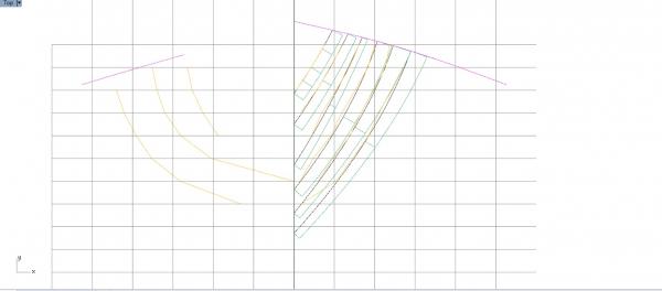
HULL LINES - IN PROCESS UPDATE It's been a few weeks since my last post, but I haven't been sitting around. I've been trying to fair the lines of the boat in between other work and home projects. At home we have been preparing our garden for spring/summer, and at work we are preparing to launch another boat - third of this class. So, it's been quite taxing on time, especially once down time with family is factored in. But, I have made enough progress to remind me why entire, high point value, multi-step, multi-week projects focused just on lines drawings and fairing in school. Because it is incredibly tedious and takes forever (to do it right at least.) Our first major project, that we started just a few weeks into the first semester of our Freshman year in college, and spent most of the rest of the semester working on, in stages, was a hand-drawn lines drawing based on a given set of offsets for something like a 12 ft sailing dinghy. And, honestly, based on how things are going with this model, I'd much rather go back to duck weights and splines rather than multi-control point mathematically defined curves in a software program. Getting a fair curve with duck weights and splines was easy compared to endless tweaking and nudging of control points. The second major project where we had to generate a set of lines from minimal data was during Senior year, and was part of our whole-senior-year design project for a containership. We used AutoCad to do the drawing and fairing of the lines, once we had generated a rough hull form that got the length, beam, draft, displacement, etc that we needed to meet design requirements. I happened to locate that particular project, so I took some screen shots and posted them. Container Ship Body Plan Container Ship Lines For that project I used a very similar method to what I am doing now - 1 - take the offsets (see previous major update...) 2 - plot the body plan to the offsets, Initial body plan from measurements 3 - transfer to the half-breadth and profile grid, Initial lines transferred from body plan 4 - then fair the waterlines (since they are generally have the least curvature and should in theory be the easiest to fair initially), First pass at waterline fairing 5 - transfer the results of fairing back to the body plan, 6 - take the first whack at fairing the new data, In-process steps 5 and 6 7 - transfer the first attempt at faired curves back to the other two views, 8 - fair the waterlines a second time, 9 - and repeat the rest of the process until the body and half-breadth plans are fair. Once I have the body plan and half-breadth plans fair, then I'll look at the profile plan, fair the buttock lines, and then fiddle with the other two views to make them all match. Like I said, tedious. Although, I think what makes this exercise more difficult than I remember the container ship being is the fact that with the containership, it was to some extent my creation, and I could take some license with the original, rough hull form and change it to make fair lines. With this boat, I have to make fair lines that MATCH a real thing. Meaning I have to be very judicial about balancing the fairness with the adherence to the measured data, and make a fair lines plan with as little deviation from the measurements as possible. I tell you all what, this project is stretching my professional skills more that I expected it would, not just my modeling skills (especially since I haven't actually MADE anything yet!) I have to remind myself that fair and accurate lines are worth the effort, because once I get to production detail design, it should save a lot of headache and minimize exclamations of l 'why doesn't this fit!' I'm sure it will happen, but likely less than if I didn't spend the time making the lines right. My hope is to have the lines complete, and a new 3D model of the hull generated, in a couple more weeks. Then, I can adjust the arrangement I decided on a couple posts back, ensure it's still functional, and proceed into detail design (which I'm already thinking about, of course....)
-
Colored pencils may work - probably a light gray. You could also look into artist's drawing pencils. They come in different 'hardnesses' - your typical #2 office pencil is hardness 'HB'; higher letters (F, H) are harder (with increasing numeric serial indicating increasing hardness - 2H, 3H, 4H, etc), and lower letters with increasing numbers (B, 2B) are softer. HB is in the middle. The harder the graphite core, the lighter the resultant line (less graphite is deposited). So, you could get a couple of the harder variety of drawing pencils, and fake in the seams and geometry that way. And, different hardnesses = subtly different 'shades of gray' that may provide a means of getting those different shades of geometry seen in the picture. But I think you could pull it off without overpowering or 'breaking the fourth wall' of the scale, so to speak. An example of a package of pencils like i'm describing can be found here: http://www.michaels.com/derwent-graphic-pencil-set-of-12-hard/10169872.html#start=29. I'm sure you can get a similar type product wherever you are located. And, you can likely buy them one-off if you only need 3 or so to get a good range of shades of gray. The other nice thing is that the harder cores stay sharp longer, so you don't need to sharpen as often. They can be made quite sharp too - sharper than you can get (operationally) with a normal pencil or colored pencil (if you make either of those that sharp, the tip crumbles and creates a mess of graphite dust (or wax, in the case of colored pencils) as soon as you touch it to paper.)
-
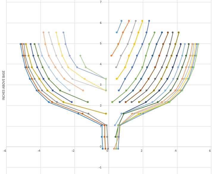
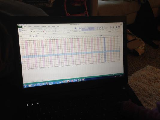
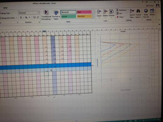
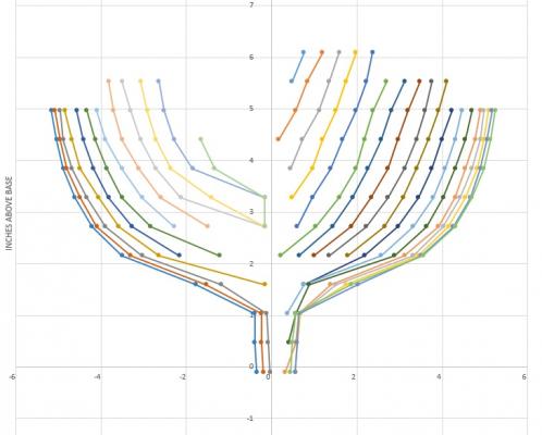
Yeah, it's a neat trick. Y-Axis is waterline height above baseline (or whatever your reference plane is) - this data set should be the same for each station; X-Axis is the offset. Each station is a different series on the chart. I manipulated the data using an if/then formula so that IF the station was aft of the maximum section, THEN the offset was made to be negative. That creates the fore/aft split around centerline seen in the chart. Drawing the sections in Excel was something we did a couple times for projects in college. It adds a visual element to the data, and also allows for identifying anomalies without having to manually plot the points and hand draft just to find something's out of wack. I really like it for that second reason. I'm much more visual in my thinking than numerical, and while I may have a suspicion the numerical progression of points doesn't seem right (for instance, a point seems like it 'jumps' too much in value given the previous points), plotting the section confirms it (or shows that there is a bilge turn or something not obvious by just looking at the model - with a black underbody, it's hard to judge the curvature. It just all looks black.) My next step will be to actually plot the data in AutoCAD and try to fair it out. The mid sections don't seem too bad, but the forward sections are pretty wonky. Don't know who was taking this data, but they did a crappy job!
-
Just stumbled on this log - this looks like a very interesting project! I'm going to have to follow along!
-
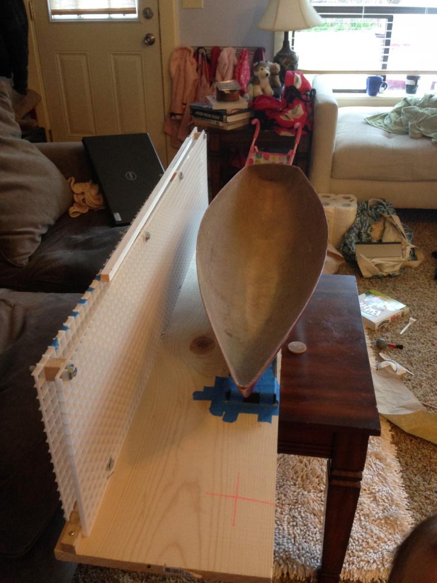
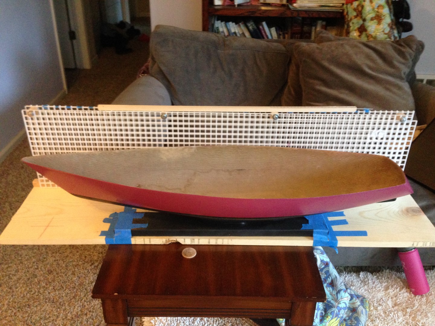
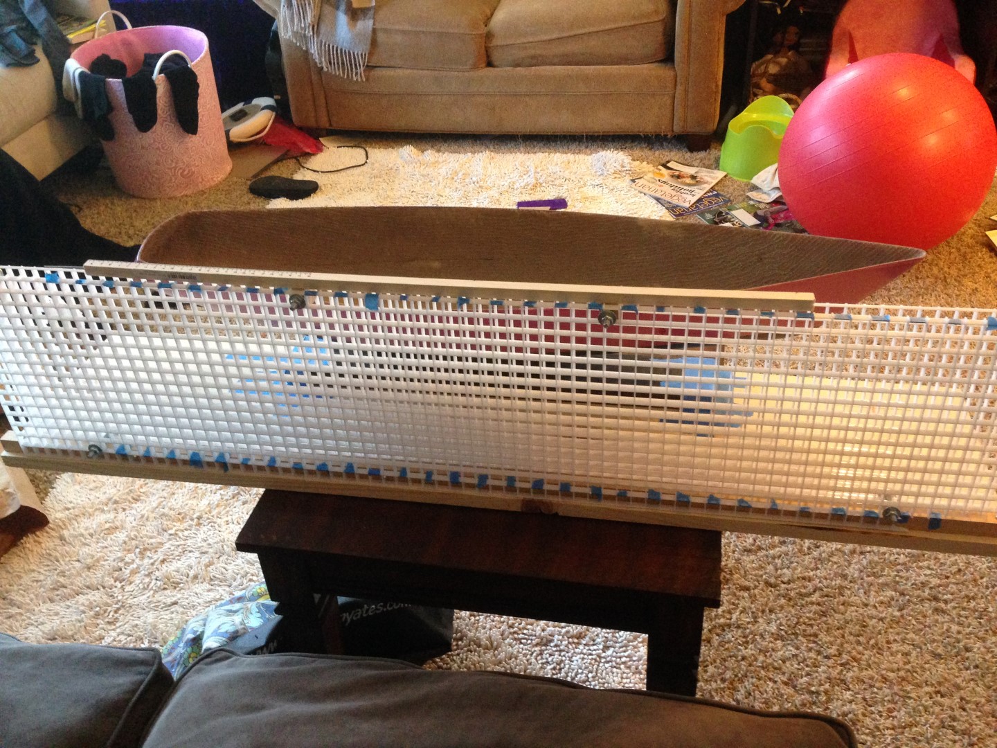
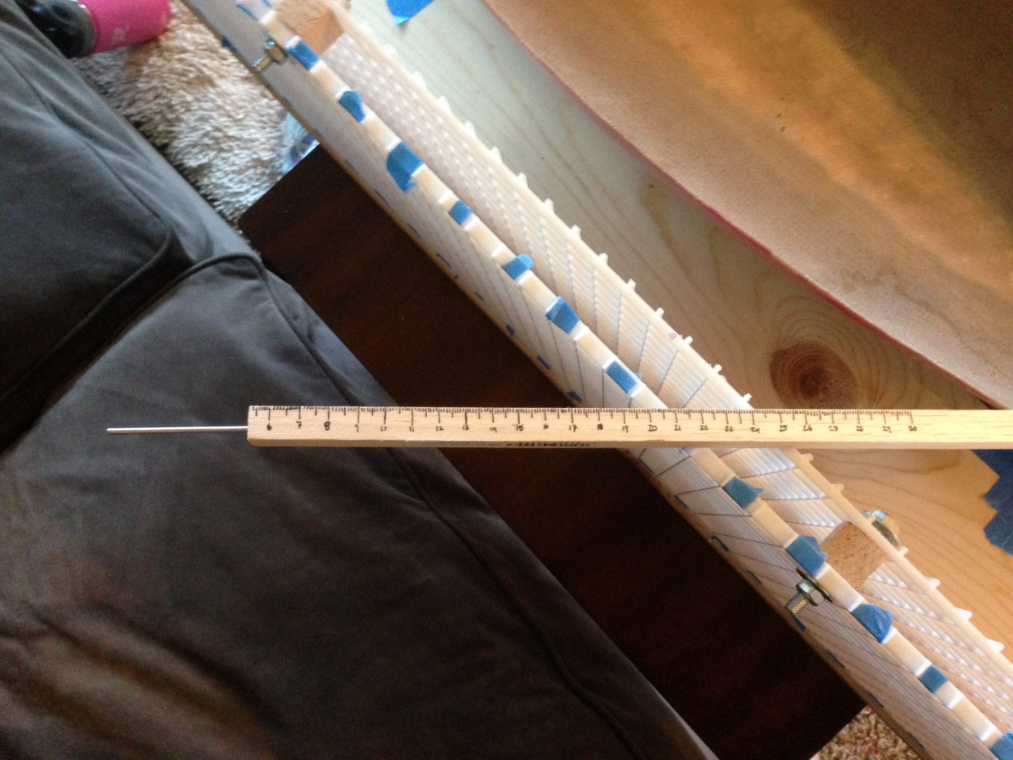
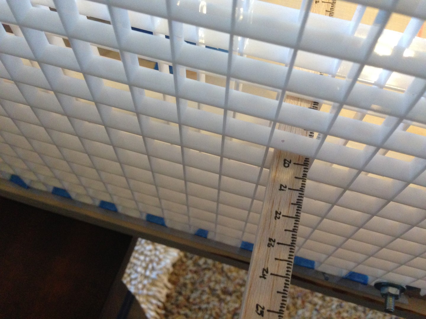
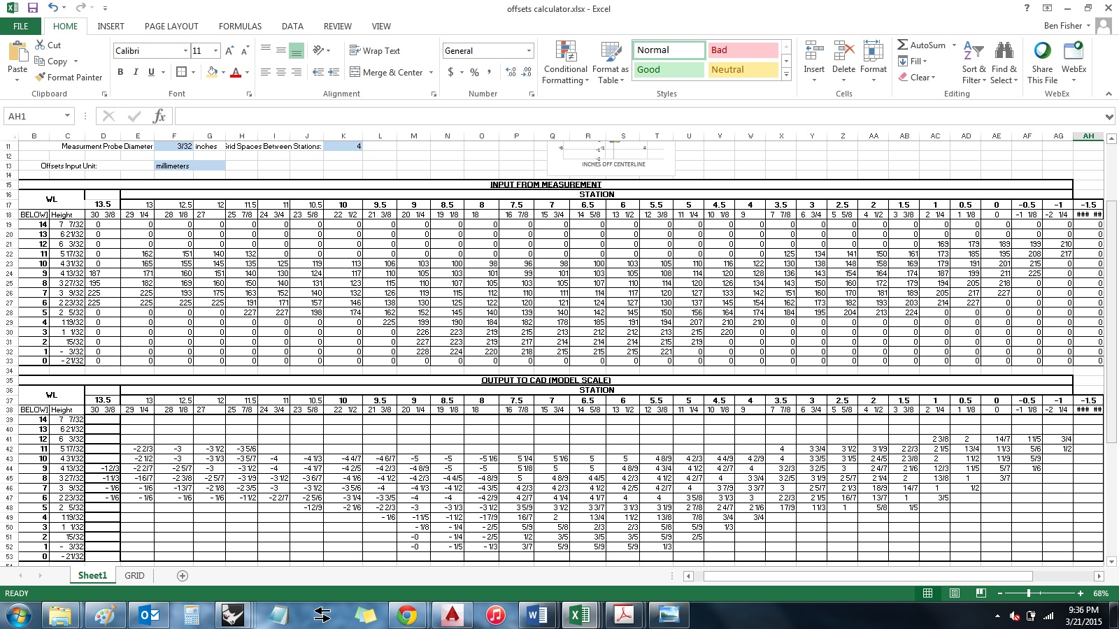
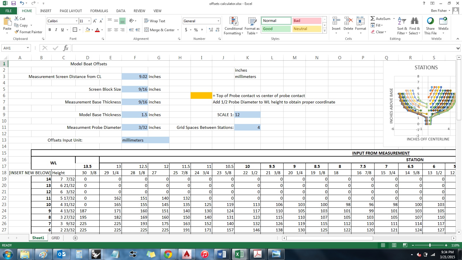
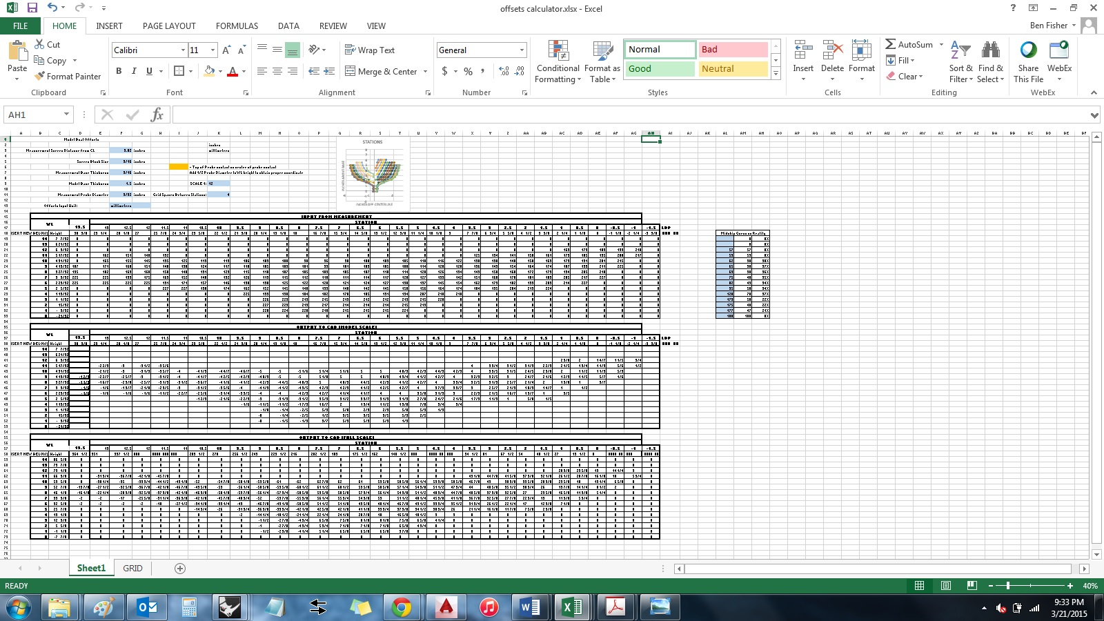
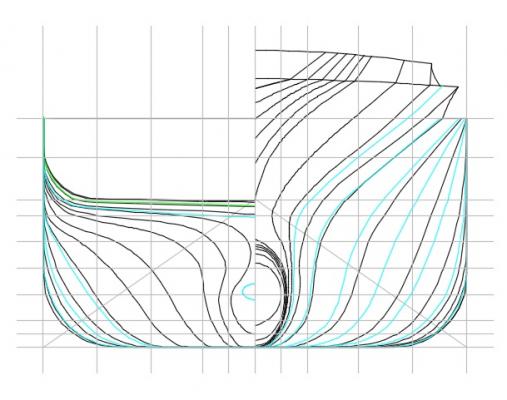
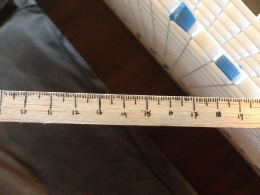
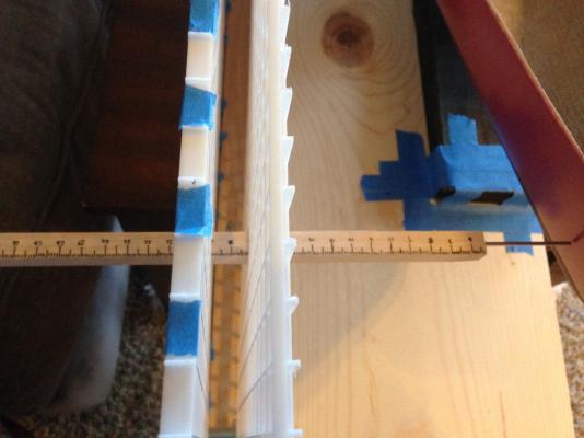
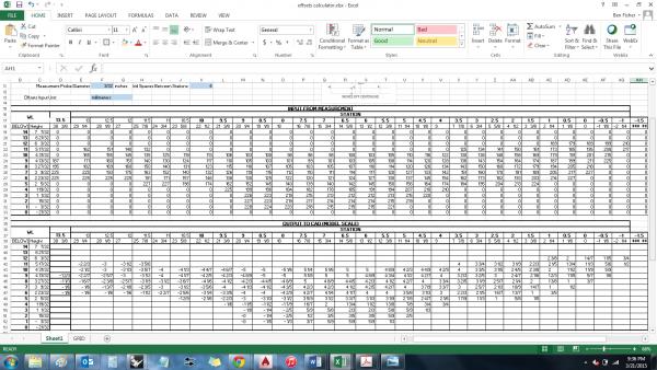
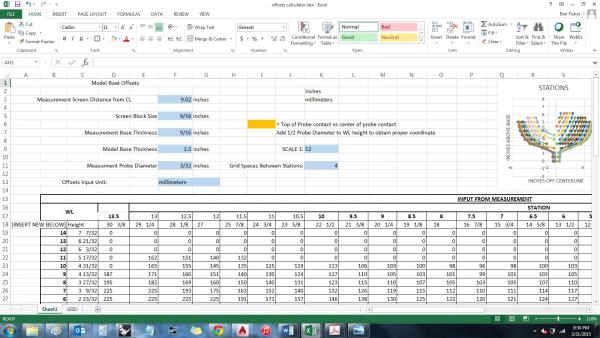
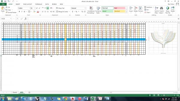
Patrick - thank you for the kind comments you offered recently! And thank you also to those who have been following along and like what I have to offer, especially since it's mostly design and planning, and not even actual building yet. I really appreciate you all taking the time to follow my thought process and, at times, offer input! Now, for the hull measuring explanation I promised in my last post. HULL MEASUREMENT - SET UP AND PROCESS So, as I mentioned in my previous post, I finally measured the hull! It took quite a bit of preparation, and then a couple hours of actual measuring. The Jig I'll start by describing the jig. It follows the concept laid out in one of the NRG shop notes - essentially it's an egg-crate style ceiling light panel, cut in half, and bolted together with some spacers. Then it's attached to a large base. I did deviate in some respects from the design laid out in the NRG article. For one, I used more bolts. (Must be an engineer thing...) Also, I didn't add end brackets - I found the assembly was sturdy enough without them. In the original design, these end brackets also seem to be what secures the egg crate assembly down. I overcame that problem using some nails drive in at an angle into my base spacer, so that the egg crate assembly can't lift off. I did make one other change from the design presented in the NRG article - since my model is small enough, and portable, I attached it right to the base of the jig using painters tape (since it was what I had). I did this because I expected that I would not be able to do all the set up, spreadsheet development and troubleshooting (to make sure it did everything I wanted the way I expected), and measuring in one sitting with a wife, toddler, and outdoor projects to attend to. I was correct in my expectation. It took one slice of time to set up the boat on the jig, another to set up the spreadsheet, another to start measuring only to be interrupted after a couple measurements, and then finally an extended period this morning to measure the whole boat. Pictures speak better than words (and by my word count so far in this build log, I owe a LOT of pictures), so I've attached some showing the whole assembly. The Measuring Stick I also made my own measuring stick using 1/2" square balsa. It reminded me of a project we had to do in 8th grade where we were given a length of balsa wood, and had to make a meter stick. I didn't quite make a meter stick, but I made something like a half meter stick, with a tiny aluminum rod sticking out to be the measurement probe, so I was hitting points on the hull. I chose to take my data in metric (millimeters) for two reasons - the increment is smaller than 1/16th inch, allowing for finer precision, and because the metric system is based on tens, it makes figuring out what the increment is a lot easier - 154 millimeters vs 6.0625 inches. But, I chose to convert back to imperial once I took the data, also for two reasons - it's more intuitive for me to think in inches in general, and most supplies I get will be categorized in inches (wood thicknesses and such) so it will be best to do detail design in inches for that reason. The Spreadsheet As I alluded to, I made a spreadsheet to do all the hard work for me. The first sheet does all the work; the second sheet is just a replica of the egg-crate screen where I can input the measurements. Sheet 1, way zoomed out to see it all. More explanation of this one below. Sheet 2, way zoomed out to see it all. Essentially just a replica of the egg-crate grid On the first sheet, I input some basic parameters - block size of the screen, distance from boat centerline to where I took the measurement, height of the base the boat is on, height of the first row of the screen, etc. Inputs section of Sheet 1 Then I made three tables - the first takes the measurement directly from the second sheet, but consolidates the date so there aren't 'empty' columns (as there are in the second sheet - I took a measurement on every other column). The second table then converts the data from table 1 into imperial units from metric (if the input measurement is metric), or just repeats the data if it was already taken in imperial units. Tables 1 and 2 on Sheet 1 Finally, table 3 scales the data to full size, based on an assigned scale factor (1:12 in my case). I was going to upload the spreadsheet I made, so it was available to anyone who would find it useful, but apparently excel sheets are not a supported uploadable file type (I checked with the moderators.) If anyone would like it, I can either (1) e-mail it, or (2) upload it to some type of file sharing site (google drive, or similar). Just either mention your interest in a reply to the post, or you can direct message me. Taking the Data With the jig, measuring stick, and spreadsheet set up, I was finally able to take data. This process went fairly smooth - it took maybe 2 hours to take all 215 data points. Taking a measurement Close up of measuring stick reading As I took the each point, I plugged the result into the spreadsheet on my laptop. I set the sheet up to plot the points as I took them, to see if there was anything super wacko going on. This ended up helping me twice when I accidentally skipped a station on the measuring grid. When I saw that the curve plotted by the points seemed to be further outboard than the trend of the last few stations made me expect, I recounted the column in the spreadsheet vs the column in the jig, and sure enough I had gone one column too far on the actual jig. I wouldn't have caught that until the very end when nothing seemed to make any sense. Laptop next to me to record data Close up of data input sheet, demonstrating the in-process tracking of the shapes of the stations HULL MEASUREMENT - INITIAL RESULTS I posted the graphical output of the initial results of the measurements in my previous post. There is a bit of fairing and follow up work to do. I still need to somehow capture the sheer line, the stem, and the stern. But these seem like much more manageable problems, and really, once I fair the data I have, I could use only that to start final production design for the interior (since there isn't really anything going in the extreme bow or stern.)


-
QUICK MILESTONE UPDATE: Finally got the boat measured!! The picture below is the initial (i.e. not cleaned up/'faired') output from the measurements I took: I will do a longer post about the setup/method, etc sometime in the near future, perhaps tonight if I get the opportunity. But I was so excited that I finally finished this major milestone, I had to do a quick post.
-
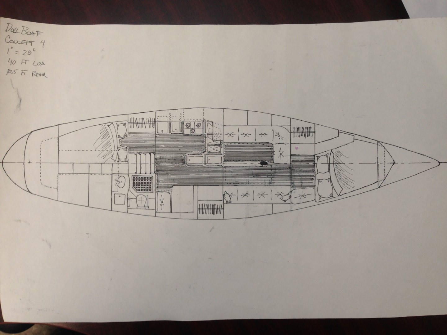
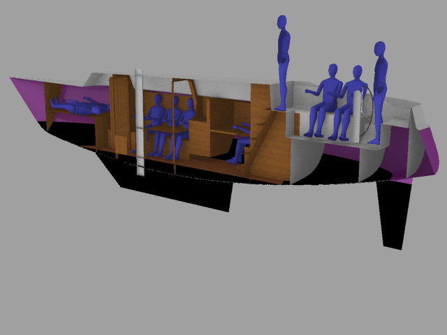
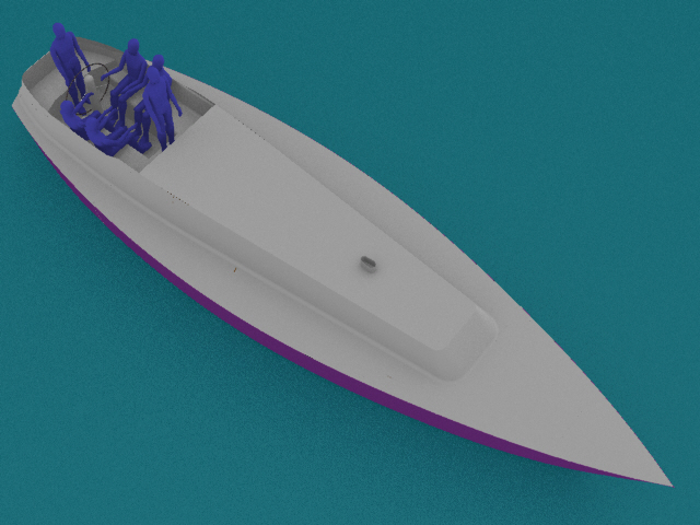
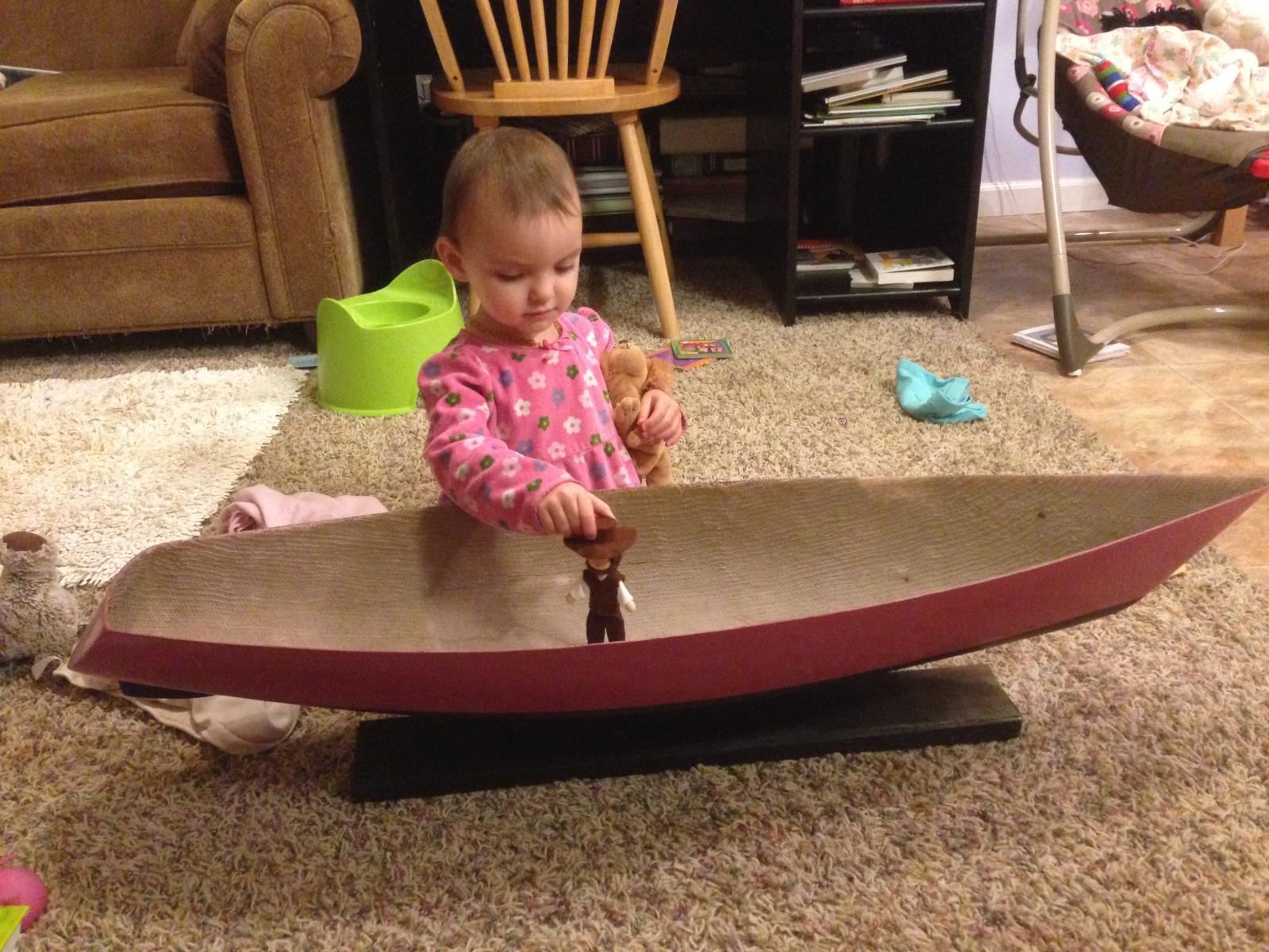
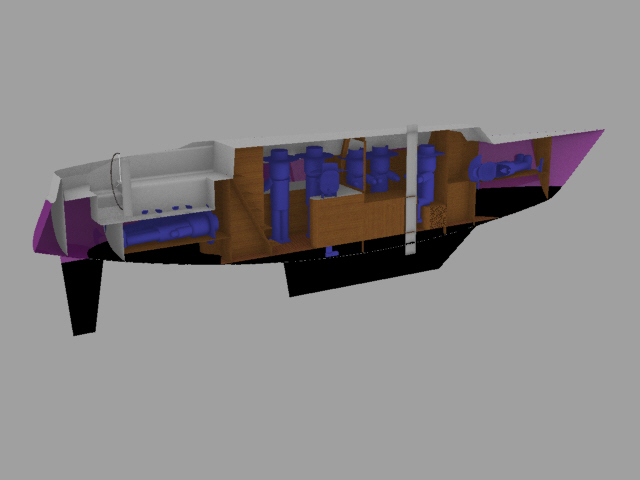
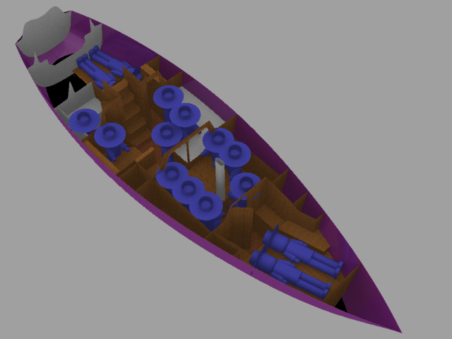
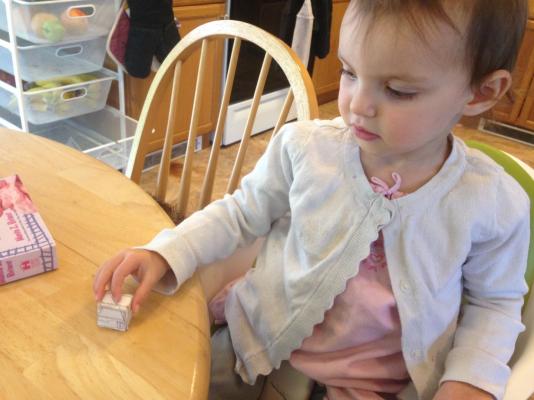
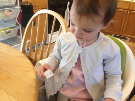
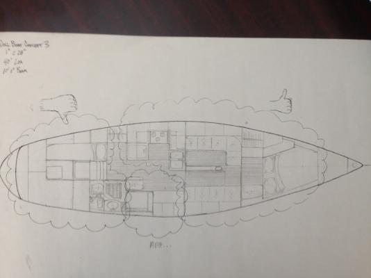
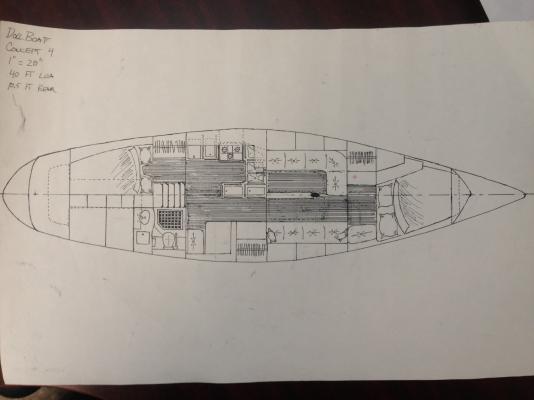
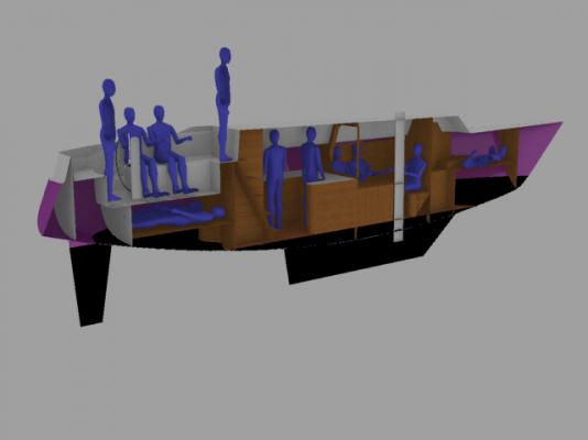
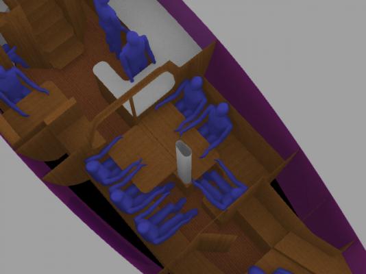
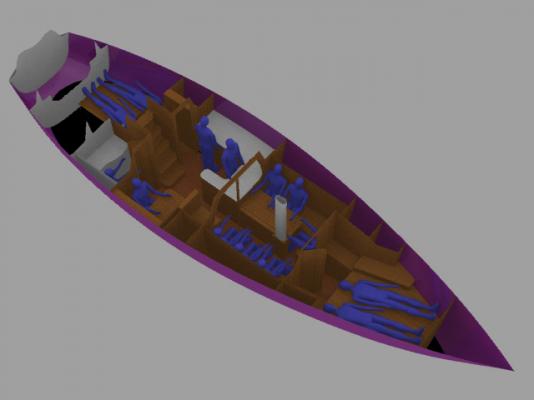
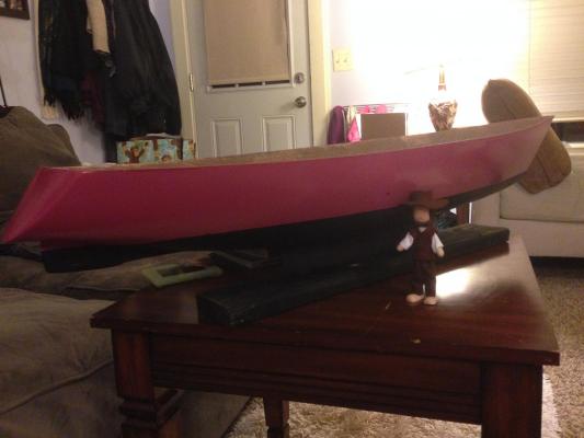
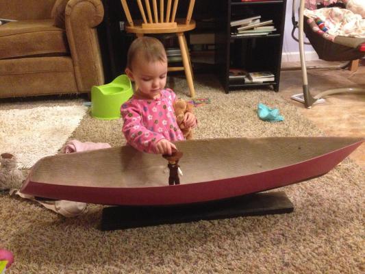
It's been a little bit since posting last, but I have been busy. Lot's of pictures/renders for this post. DESIGN DEVELOPMENT (CONTINUED) First off, I have finally locked in the scale I intend to use. The first doll, 'Pa', arrived a couple weeks ago. Here he is next to the boat: And here is my little girl playing with him in the boat (she can say 'Boat' now. One of her favorite words. I approve. ) I used a pair of calipers to measure the doll, so I could make a 3D model approximation. But, while I was waiting for the doll to arrive, I put together a couple more concept sketches for a 1:12 scale. The first attempt at a 1:12 scale wasn't so hot. See below: There were some areas that I think mostly worked ok, as indicated by the region with the thumbs up. There was a little bit that I wasn't to thrilled with, but seemed functional. I called this area 'Meh...' And then, there were areas that were just odd shaped and non-functional, hence the thumbs down. So, I took the areas that were good, and revised the rest, to develop the second 1:12 scale concept, below: This one I liked much better, so I went ahead and 3D modeled it. A series of shots of the modeled layout are below (again, the blue figures represent a male in the 95th percentile for size) Overall Top Isometric: Overall Interior Isometric: Isometric Detail of the Dining area: Centerline looking port: Centerline looking starboard: Back to Pa. Like I said, I modeled him up. Then I scaled him up by 12 to see the fit with the full size arrangement I had just finished modeling. The fit was pretty good, but I must say the disproportionateness really comes out when he's scale up by 12. Overall Interior Isometric: Centerline looking Port: Centerline looking Starboard: So, as can be seen, the size fits about right. To take this to 1:16, like I had intended, he gets freakishly large and wouldn't even pass for a 'that looks about right' scale (let alone have enough room to be played with). To conclude this post, I want to again express my appreciation for the input. I likely would have gone far down my original path and then found the boat to be non-functional. With this adjustment to scale, I think that I will be able to make a functional boat - and to Bob's point, I can outsource many items I would have had to make! (Not that I won't make some of my own custom things anyway.) If you have noticed, I've also revised the thread title, since the boat's not 53 ft anymore... In my next update, I'll go into the details of measuring the hull form (finally!), which is what I am currently in the process of doing. And if I figure out a way to post downloadable files, I'll share the Excel sheet I put together to do all the work of taking my measurements and turning them into useable offsets.


-
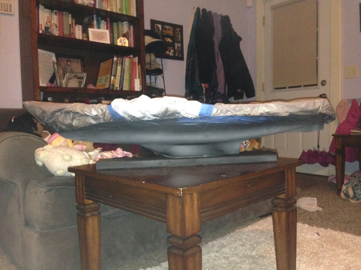
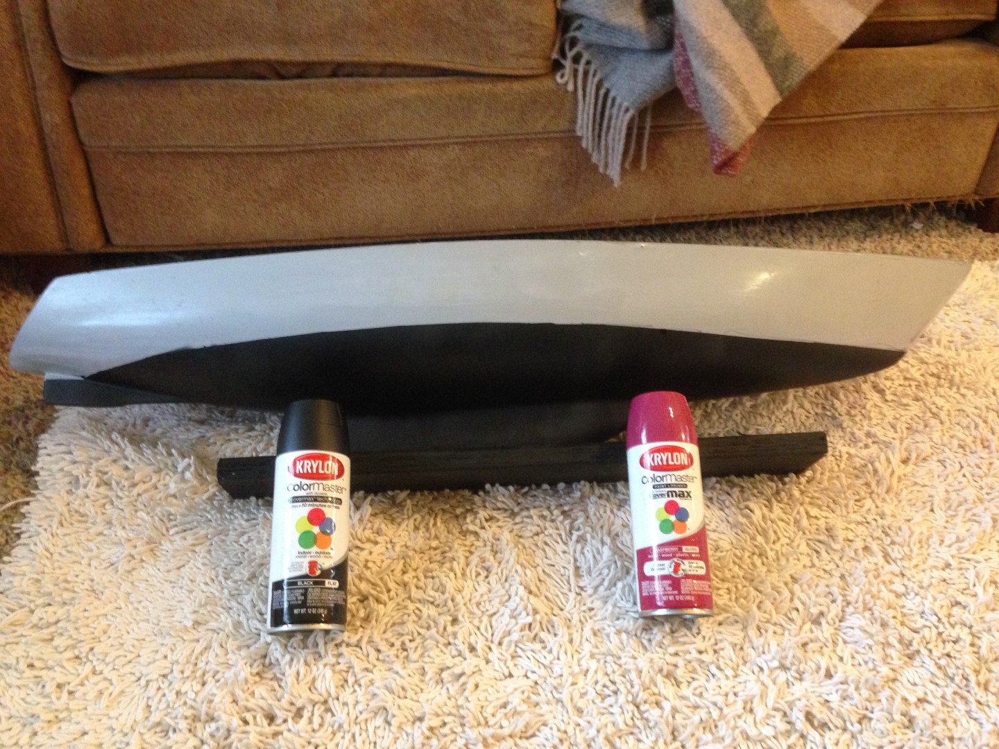
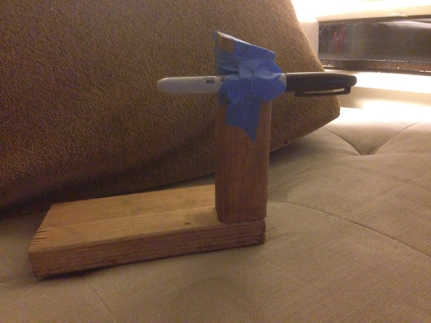
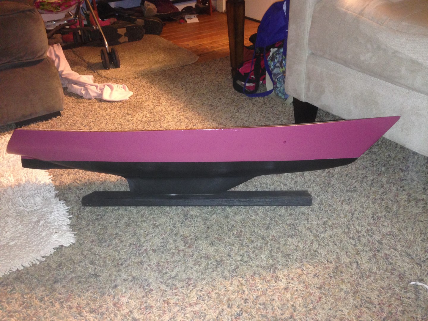
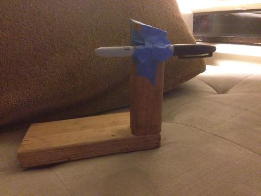
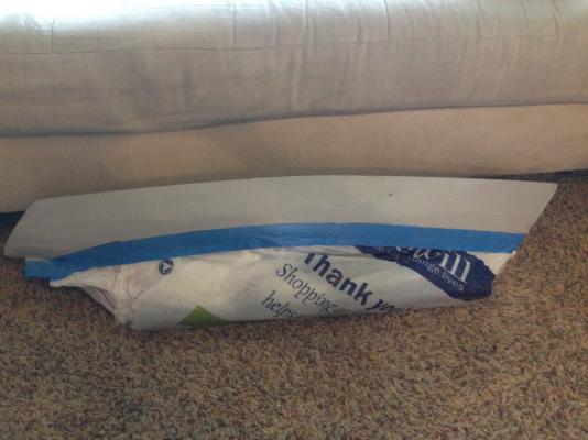
HULL PAINTING While I have been doing arrangement design, I have been able to go ahead and paint the hull. I marked the waterline with a sharpie attached to a gizmo I made. I got the idea somewhere, but I can't recall exactly where. But it's basically a couple pieces of scrap wood i had laying around from one of our garden projects. A larger piece for the base, and a narrow tall piece as a marker holder. I measured up from the bottom to where I wanted the waterline (taking into account the thickness of the base I have the boat on), and then taped the marker in place. A picture is below: It mostly worked. The marker was kind of dry, and where the bilge rounding is extreme near the stern, it got weird. But, it was good enough to lay tape against, which I then tweaked and eyeballed until I was happy that it was a line mostly parallel to baseline. I started with the bottom paint. I chose black for the bottom anti-foulant. Maybe it's just my experience having done only black and gray boats in my career to date, but I like the look of black on small boats. It took several coats, and learning how to actually use spray paint effectively. The nice thing about the black is that it makes it easy to see where the paint is too thin. This is also the annoying thing about black. A picture of the hull after the first coat of black spray paint is below: After a bunch more coats, the bottom was finished. Below is a picture of the finished bottom, with the masking removed. I've also put the spray paints I'm using in the picture: Then I masked the lower hull. For masking both the upper and lower hulls, I used standard blue painter's tape, double layered. Part of the tape was used to attach a series of plastic bags to cover the rest of the area not being painted. Since I was using spray paint, I was concerned about overspray, hence why I completely masked the unpainted areas. Masking is shown below: With the bottom masked, I applied the top paint, which is a glossy Raspberry Pink. (Incidentally, this is the first time I've ever spray painted something pink. I believe I may now apply for official membership to the Dads of Daughters club....) The glossy paint worked a lot differently than the flat paint. It ended up applying a lot thicker than the black, and it even had some drips and runs after the first painting. So, once it was dry I used a fine to medium sandpaper and wet sanded it to get rid of the blotches and runs. I was much less trigger happy with the second painting, doing a series of quick, light sprays. The final result came out much better, and with the masking removed it looks like a proper boat now! HULL FORM MEASUREMENT I've also gone ahead and purchased a 6-inch contour gauge, which I was hoping to use to take stations from the hull. Two problems arose during my attempt, though. The first was that the depth of the boat is greater than 6 inches, so I couldn't get a complete station in one go. The second was the the curvature is too broad. Essentially, since the hull has a lot of curvature, and the scale is so much larger than the normal uses of contour gauges, the pins bunched up and seized at the turn of the bilge. So, it isn't really effective for taking station shapes. I'm sure I will find some use for it that will supplement taking offsets, but taking offsets is indeed what I need to do. I'm hoping to get to the hardware store next weekend to get egg-crate light panels to take offsets in a manner similar to one of the NRG's articles on the subject. (I would have gone over the holiday weekend we just had, but apparently we have a thing called a 'budget' and I 'spent mine' already for the month...) That's all the current progress with the physical hull; I have made some progress in design development that I will post a little later this week. I'm also waiting for Pa Pioneer, the first doll in the collection, so I can take some measurements and make a cardboard mock-up of a couple spaces in different scales to lock in the one which works best.


-
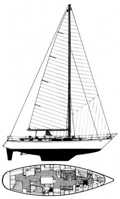
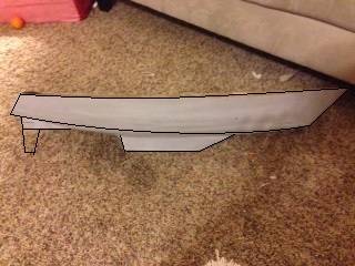
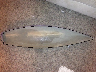
Update on the search for scale: After a little more digging, and recalling that the person I got the model from mentioned something that led me to believe it was a model of a Gulfstar yacht, I think that I've found the parent hull. I believe that the model may be of a Gulfstar 60 hull - see pics below. I added a rough outline to the pics of the model, since it's hard to see. The shapes look right, and a quick check of dims, assuming published Loa of 60.50 ft and published beam of 16 ft and model Loa of 40", leads to a model beam of 10.56" - I measured 10.5" using my eye gauge for locating max beam, and looking at the tape, and saying 'eh, 10.5 looks close enough'. So, 10.56" is well within the measurement error of my process. In summary - shape and dimensions lead me to the conclusion that the hull model is of a Gulfstar 60. So now I know it was intended to be a roughly 1:18 scale model of that hull, which would explain why the proportions don't work as well the larger the scale gets, to the point where the beam is 2-3 ft narrower than most boats at 1:12. I am leaning back toward thinking the 1:16 scale is the best compromise. But I'm going to wait to actually get one of the figures here before making the final call. In the meantime, I'll finish writing the spec and generate another concept or two. It was an interesting little detour to do a detailed review of so many boats of different sizes (beyond just finding some representative examples of layouts), which I likely would not have done were it not for the thoughts offered regarding scale and the practical side of being a 'doll boat.'
-
Just jumped on this log. I was thinking in the exact same direction as your modular construction of the interior, so it's great to see it in practice, and work successfully in your small scale! I would've loved to see how you were going to do the removable deck/cabin, since that is also where I was headed, but I do really like the partially skeletonized look of some of the builds I've seen, like Patrick's miniatures (at one size extreme) and EdT's Young America (at the other!) I enjoy how it shows off the structure - especially in the larger scales where you can really see the details of how all the pieces go together. Looking forward to following the rest of the build.
-
As a P.S. - in my research, I've been finding that many boats in the 38 - 55 foot range do not have similar proportions to mine. They all (to scale) have at least another foot of beam, many times even more in the 40' range. It makes it difficult to find layouts that work with a narrow beam. If a I use a 1:12 scale, this hull would have a deck beam of 10-1/2 ft. Many 38-42 ft boats I looked at had a common beam of 12.17 ft (I bet there was some racing rule or class design or something that set that...), and many others had beams in the 12-13 ft range (or more!). You can do a lot with 3 extra feet of beam! I only found 4-6 layouts (out of the several hundred I perused through in the 38-42 ft range) that had beams even comparable - and those were generally a foot or so beamier. Only a couple had beams less than 11 ft. So, that's my other challenge, having a narrow beam in proportion to other boats that would be similar length to scale. Incidentally, the proportions seem to work more the larger the boat gets (i.e. the smaller the scale). The few 52 ft boats I looked at only had another foot of beam to scale, compared with 2-3 ft at the 38-42 ft length range.
-
I again appreciate all the input! It helps to have multiple perspectives to think things through. Antony - I appreciate the insight from your own experiences. That further motivates my decision to try to do this in steps - step one being a not-fully-detailed model meant to be played with. No intricate things like light fixtures or hinged cupboards (or, if there are intricate things, I make them easy to replace, and make a bunch up front with replacement in mind.) It's all about expectations, I guess. And the points about scale and doll size are good ones. I am actually thinking about getting one of the larger dolls to measure it, and make sure that the ergonomics work with the doll scaled up (rather than a person scaled down!). I am also considering Cap'n Bob's comments regarding scale - that is something I found too, that many objects are in 1:12 scale. The upside of a boat is that not many things commercially available 'work' for boats - boats have odd shapes and sizes for beds, all the furnishings are built in, and the furnishings themselves are more....creative. Lots of odd shapes and sizes. But the point about things like pots and pans and other 'loose' items is a good one. I have to decide up front how many loose items I want to provide. (More loose items = more things to lose. Or to be left out and stepped on in the middle of the night. Oh - just got the worst idea. Scale legos for the children on board!) But, I have spent a little time rethinking the arrangement in a 1:12 scale - meaning a roughly 40' LOA. Still a good size boat for any family, but I think it would require cutting out one of the features that I've really been hoping to work in - a workbench or workshop room. To incorporate that into a 40 footer would, I think, reduce the number of berths too much, and would eliminate a quarter berth or aft stateroom (which is a preferable sleeping location underway...from what I've read). I do dislike that part of designing that requires compromises. But I suppose it's more of a challenge. That, or I could just conform to the layouts I've seen in basically every other 40 footer with a similar hull style. I suspect they are the way they are because they work. Reinventing the wheel takes a lot of effort... but at least it involves learning why and how it got invented in the first place. Patrick - My intent wasn't to have the interior removable, but then again, I don't have much experience with normal doll-houses. I know the furniture is removable (but it is in a real house, too.) A sailboat's furniture is fixed in place, though. Many times it's part of the vessel structure. So, my intent was that the boat, as a doll-house substitute, would be open topped and the dolls played with inside. That said, If the joiner bulkheads and furniture above the sole are fixed to the sole, I could have the entire thing lift out. (I even thought of building two interior options - a 1:12 scale one for the doll house, and then a 1:16 scale one that could replace it later. Then I realized that I had been thinking about this too long and had descended into delusion...) More to come as I work this out. I really do appreciate the input. Designing in a vacuum = a poor design.