Moxis
-
Posts
314 -
Joined
-
Last visited
Content Type
Profiles
Forums
Gallery
Events
Everything posted by Moxis
-
 Thanks Chuck for your message. I also have tried to find this material everywhere, because it would suit perfectly also for cutting with cnc router (I think). I have tried to find a substitute for photo etched parts which could be produced with a router, by trying different plastics, but without success. The best material so far has been thin aircraft plywood, or a product called Sikablock, but it is very difficult to cut slices thin enough (<0,5 mm) of this material. So laserboard would be the perfect answer for my needs, but I cannot understand why it is so difficult to get. Maybe I have to try your link, but I doubt they will not sell it for private persons, especially when they are situated on the other side of the globe. But I wonder where the railroaders are getting their stuff?
 -
Thanks amateur, just that. I have to place my order immediately. The only thing is that I thought it to be thinner. But this is a good start.
-
After having read Chuck's wonderful build log about the cutter Cheerful, I came to the page where he describes having made certain parts of laserboard. This material seems to be outstanding when producing tiny parts either with laser or maybe also router. But where to get this material and which thicknesses are available? After a short googling it seems that nobody knows this material, especially in Europe.
-
Thanks Denis and Ron. This is what I was suspecting. No shortcut to happiness.
-
I have always thought, how simple it would be to scan the bulkheads from the drawings, and then let the cnc router to cut them. Easy and accurate method to produce bulkheads. But in reality not so. Because scanned pictures are often in bitmap format and include a lot of faulty points which must first be cleaned away, and then the pictures must be vectorized, to have finally a drawing which can be cut with a router. So I wonder if there exist any programs that would do this cleaning and bitmap/vectorizing conversion automatically to be able to produce bulkheads or frames easily and accurately?
-
Balsa as bow/stern filler
Moxis replied to Roks82's topic in Building, Framing, Planking and plating a ships hull and deck
Balsa wood has been used for decades as construction material for model airplanes. Also in very thin strips. And they are only glued together without any other fasteners, and still the constructions are/were very rigid. Filling blocks used in shipmodels are solid wood, much more stronger than thin strips, so I don't know any reason why they couldn't be used. And as Roks82 said, they are much easier to sand as heavier wood. -
Thanks Michael for a very comprehensive explanation about making your collet system. Your skills for metalwork are beyond mine, so I have to rely on the purchased equipment. I have a set of ER16 collets which are not used very much so far, but inspired about your writing, have to be considered seriously again. I think the key to resolve my problem is to use those drill bits with 1/4 " shanks, so that when changing the drill diameter, the shank of it and the collet remains unchanged. The smallest milling/drilling cutter I have is a 0,3 mm one, with which I have managed to drill a hole or two with very careful feeding of the quill, but breaking of the cutter has been very near due to the poor quality of the chuck. Another story is the rotation speed of the machine, which in my case is also very limited, but would be the reason to adopt that high quality small dc motor, which rotates easily 50.000 or more rpm.
-
Wonderful work Michael, I really like your machine tools and would like to steal a couple of ideas for my own machines too. I have an Optimum BF20 Vario milling machine, which I am very satisfied, but one thing bothers me when using tiny milling cutters or drill bits: The chuck which should be the most accurate available for this machine, is not running completely true. I have used also small collets which run better, but are not always convenient when changing the drilling bit, because at the same time you have to change the collet too. So my question: Which chuck are you using with your micro drill press, and how accurately is it running?
-
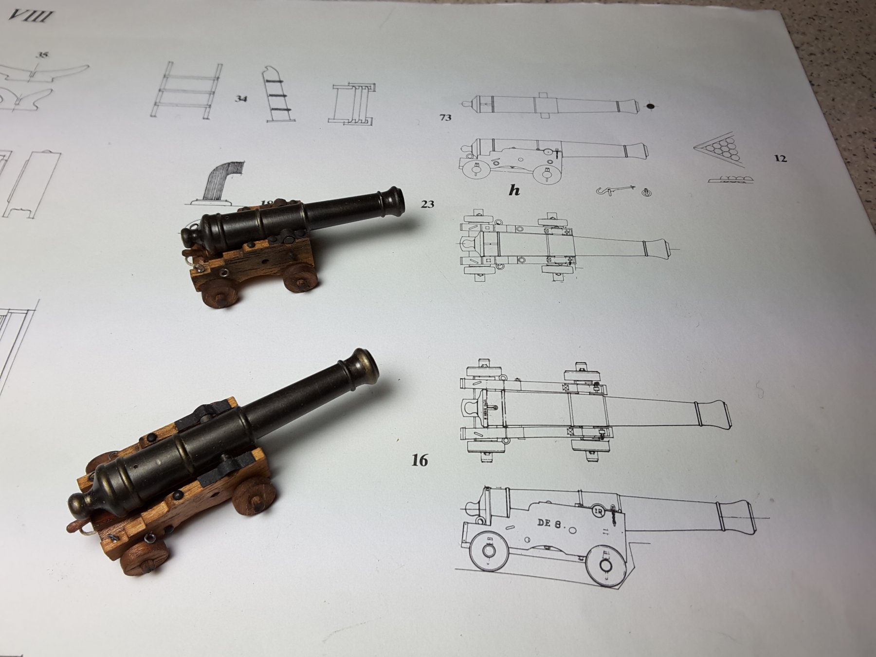
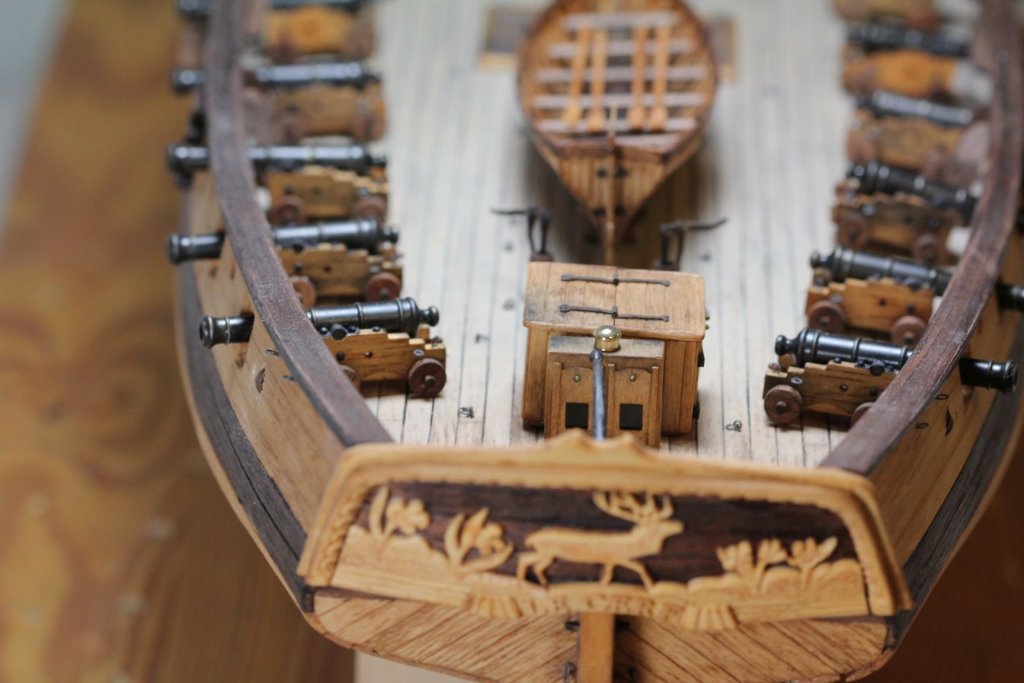
At least Ancre`s drawing for cutter Le Cerf ( built 1779 - 1780) suggests the lower type. Funny thing is that I have just finished the 16 pcs 6 pounders, and still working with the 8 pounders for my model:

-
Thanks Bill, that was my first carving ever made with a rotary tool.
-
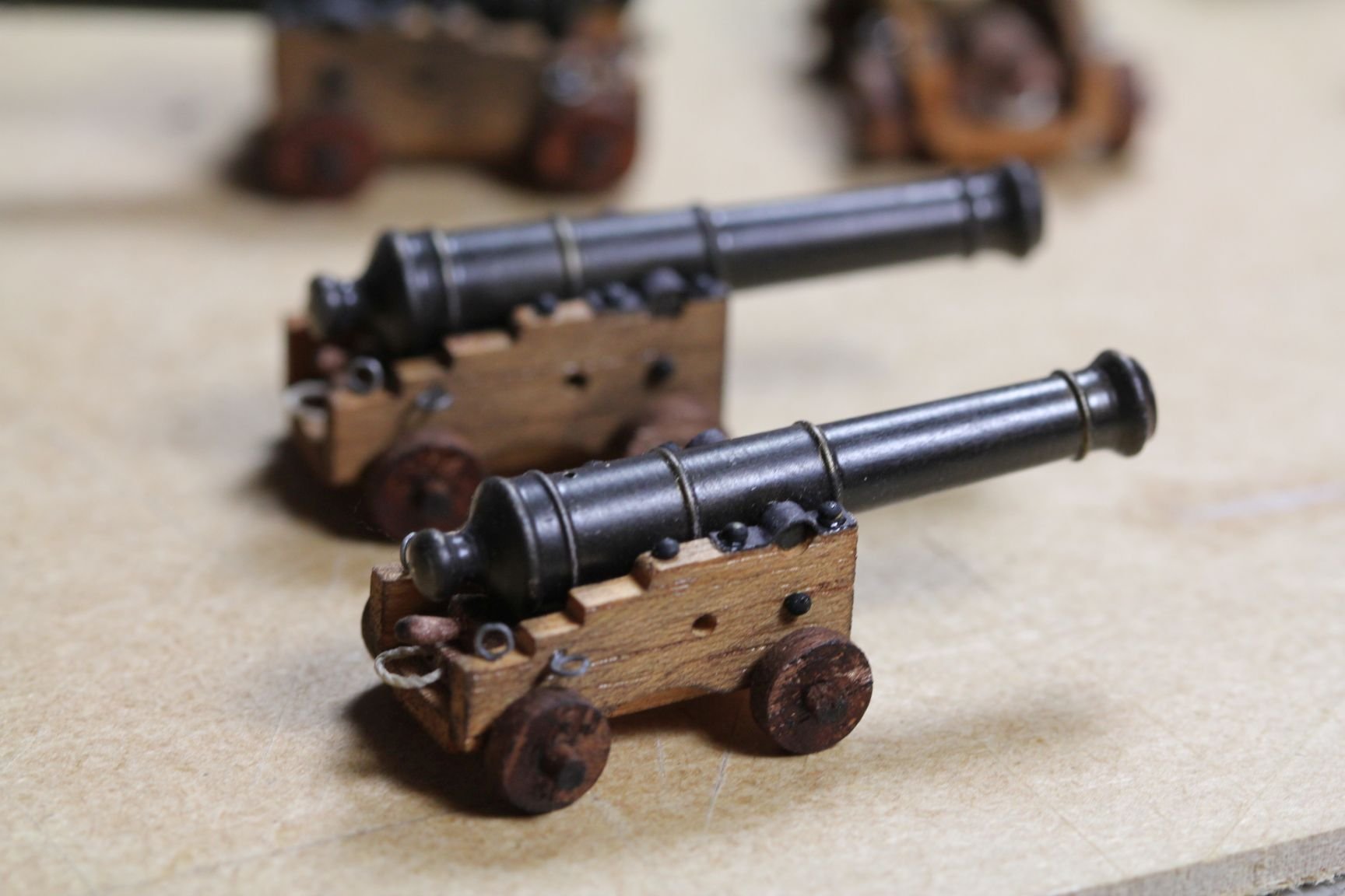
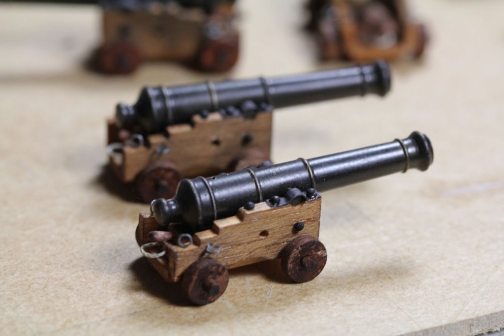
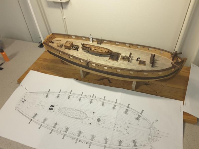
And here they are finally on the deck of Le Cerf. Not yet rigged but otherwise finished: Carriages made. I know that there should be a thin chain at the trunnion fastening piece, but I couldn`t find chain thin enough. The smallest chain I found was a silvery one made of 0,3 mm wire, but that looked like anchor chain at this scale. So instead of chains small rivets:
-
Thank you Ron for your explanation about those location bumps & indentations. They are exactly for that reason! And thank you Allan for your link. I must study it carefully and use this method the next time I make the castings.
-
Thanks Allan for your message, and all "likes" as well. It is true that the seam which builds up if you use a two part mold, is a nuisance. So far however I have managed to remove it by gently cutting it away with a sharp blade and sanding the rest. The single piece mold is very interesting solution, of which I would gladly like to know more. Like which rubber are you using, and how do you manage to take a casting away without breaking the mold. A good idea is also to provide a small indentation for trunnion drilling. So far I have managed to drill the holes with careful starting of the drilling. I have left a small indentation only to the business end of the barrel to be able to drill the hole for cannonball accurately centric, that was easy to make when turning the master in the lathe.
-
I was thinking this a lot, and decided to make casting without the trunnions, because I wanted to keep the cast as simple as possible. With trunnions in place there is a risk that the resin does not fill the cavern completely because there always remain pockets filled with air. And it is relatively simple work to drill the holes and add them afterwards.
-
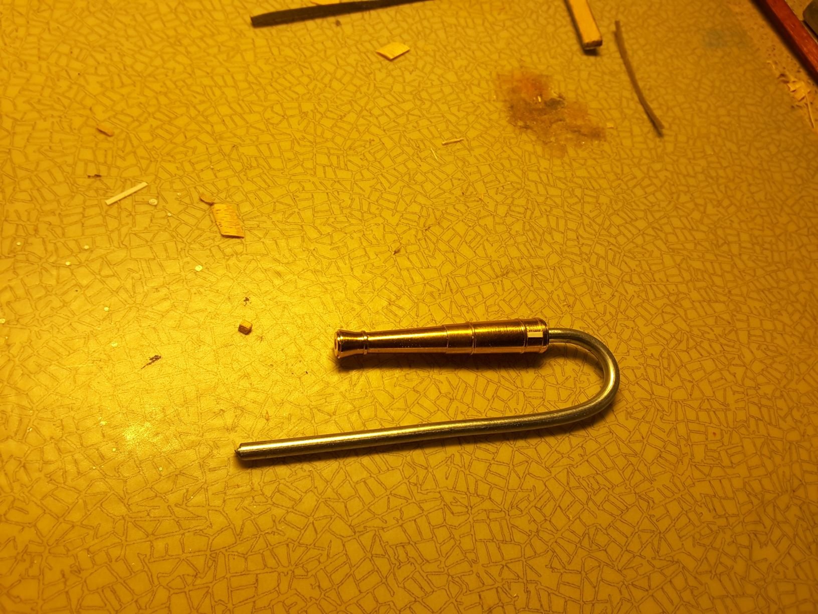
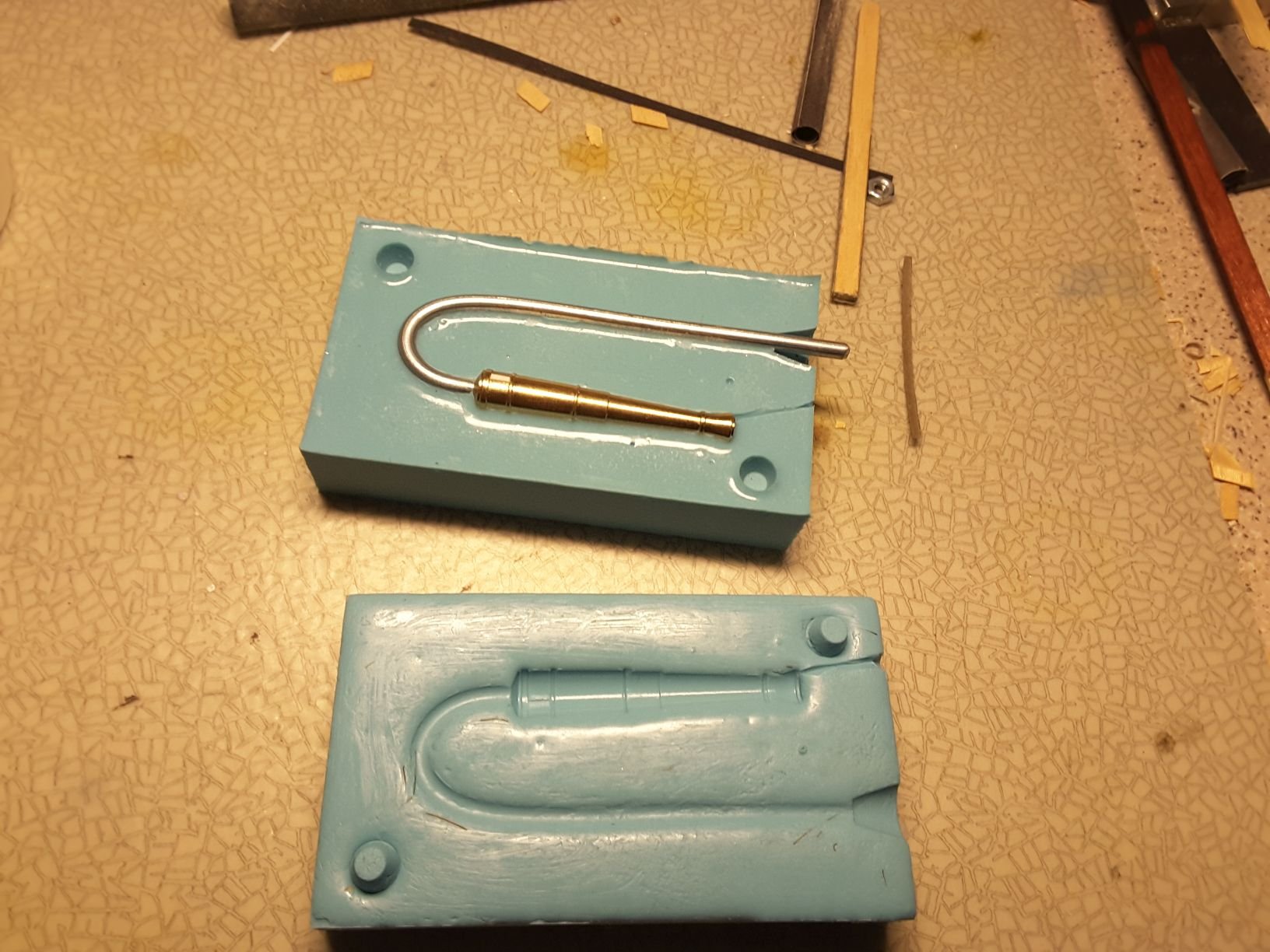
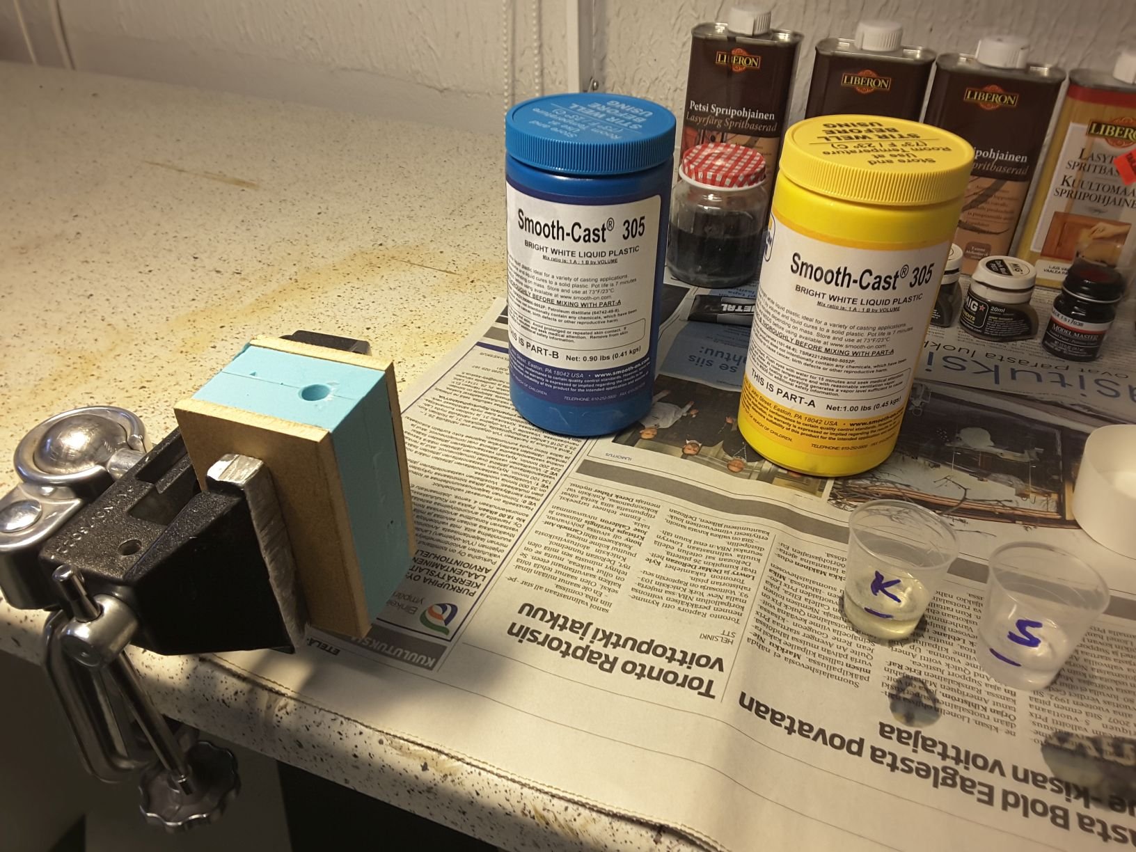
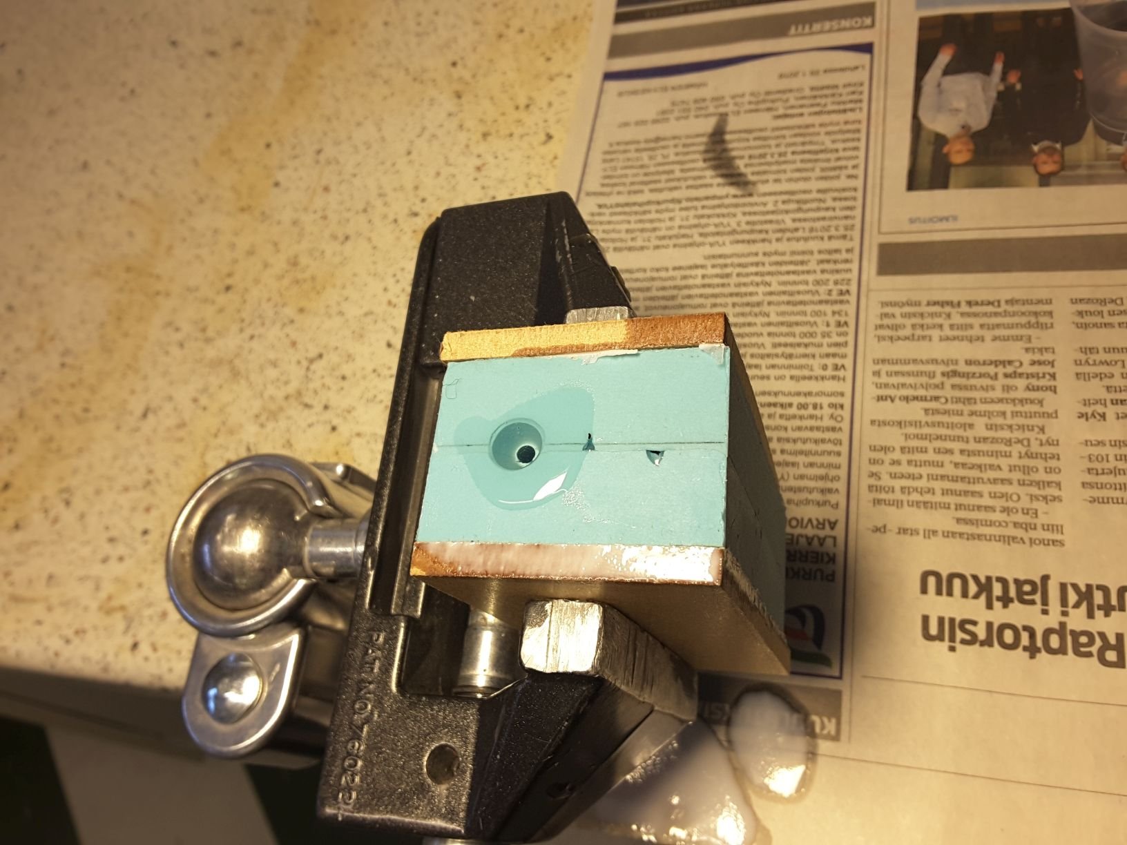
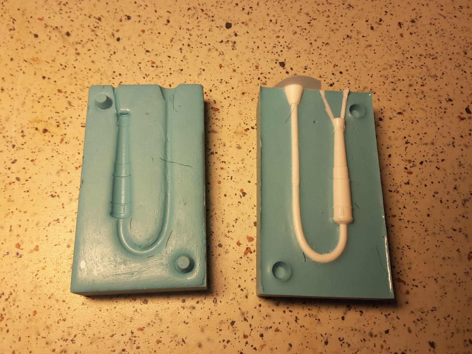
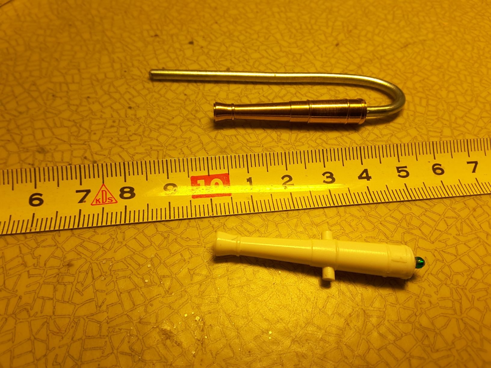
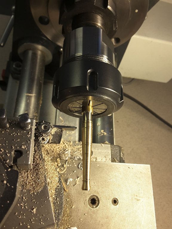
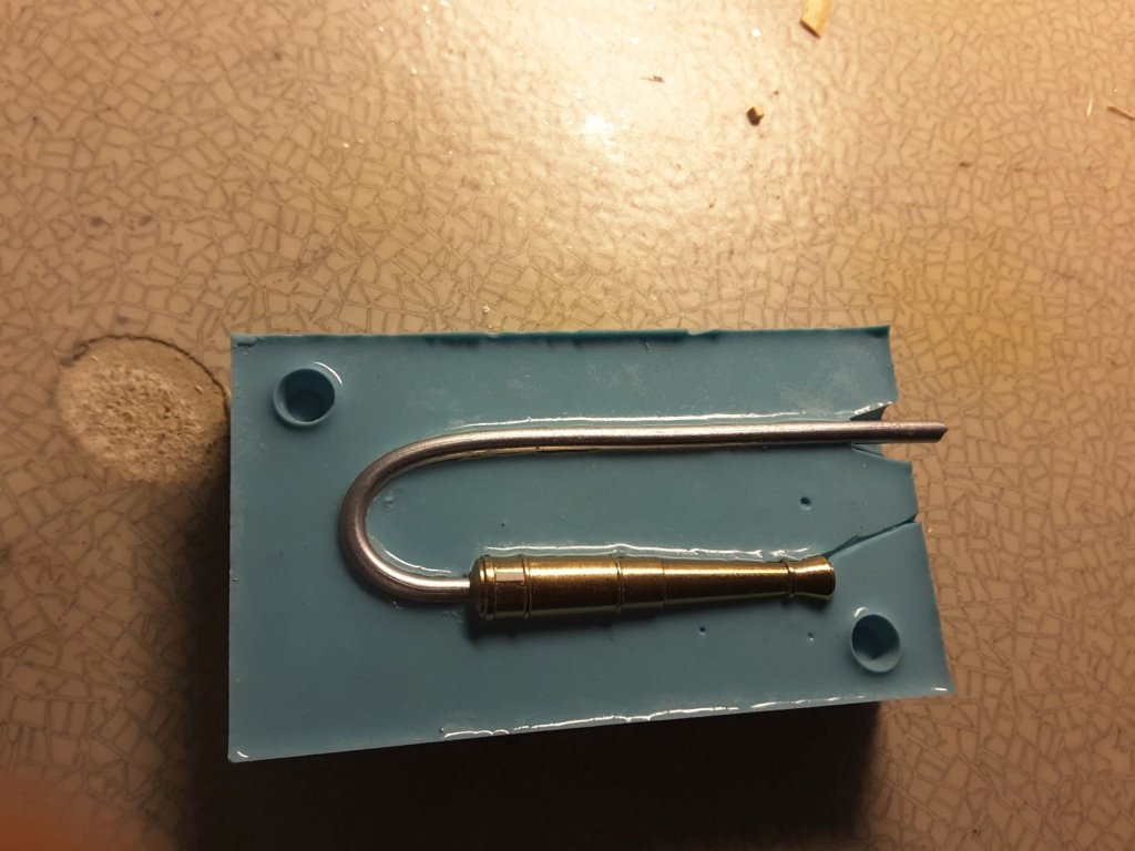
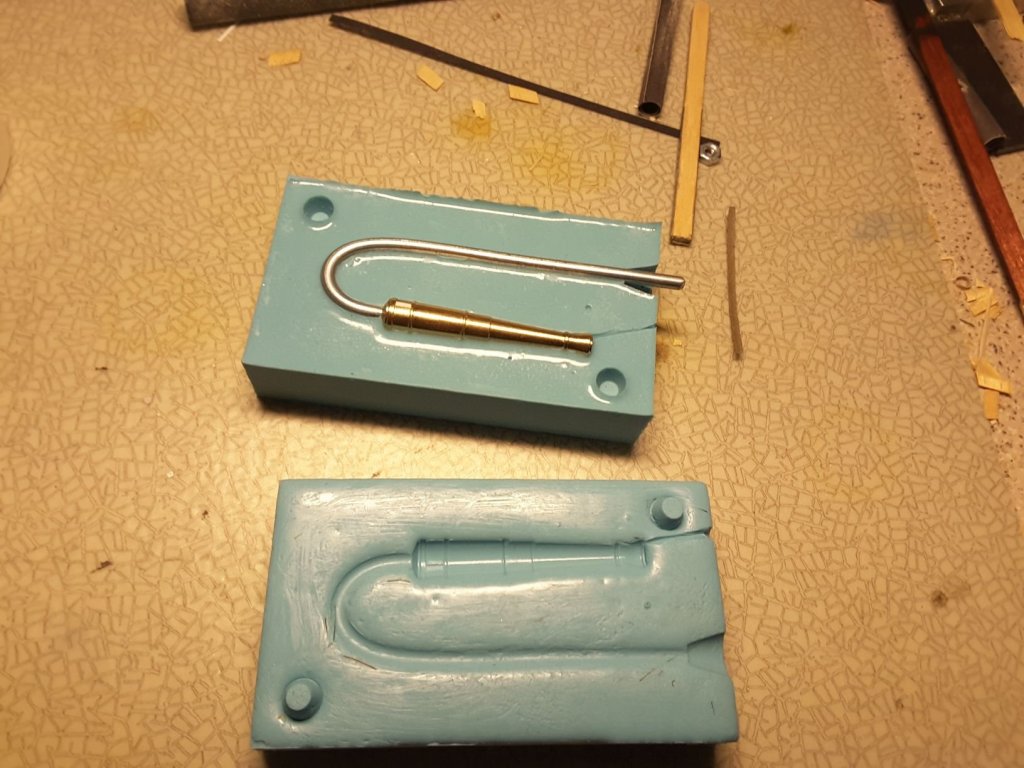
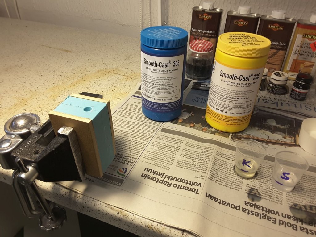
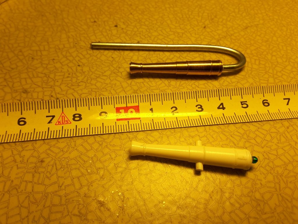
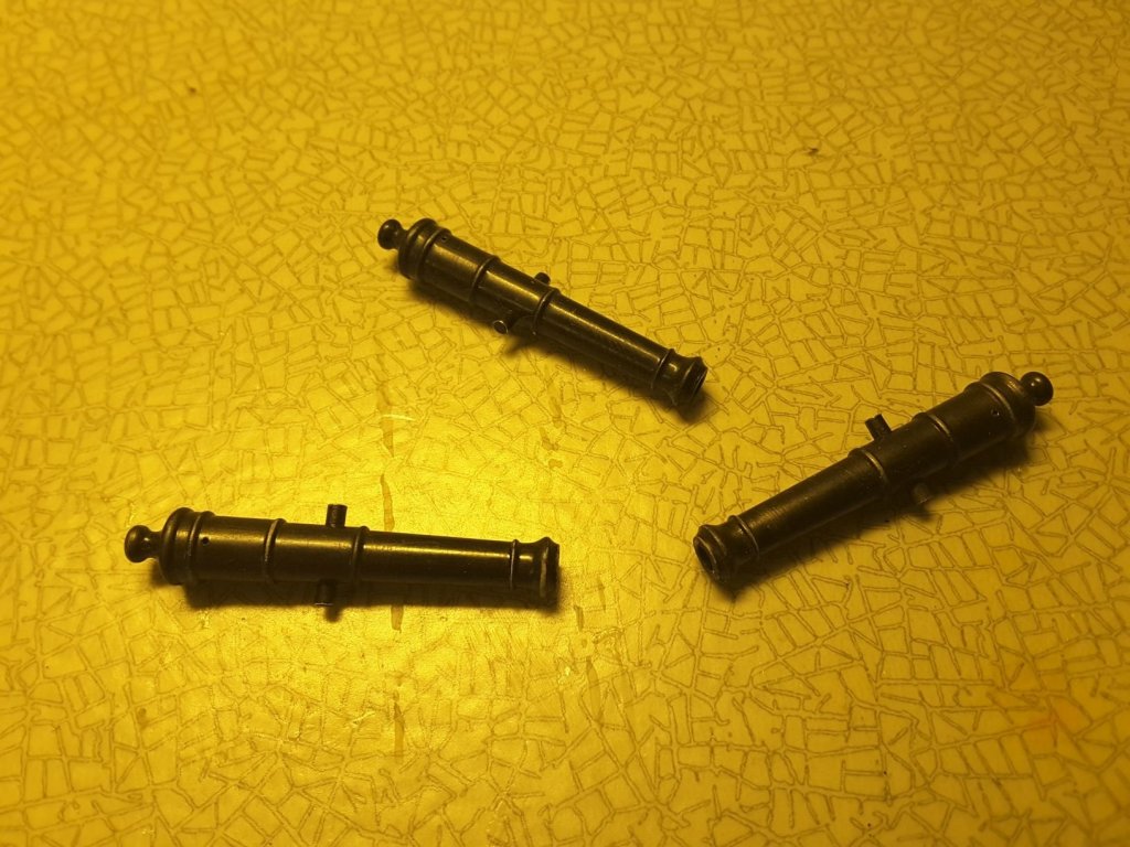
First I decided not to issue this at all, but after having seen here elsewhere Chuck`s tutorial about casting the thin carvings out of PU, I decided to publish also my method to cast cannon barrels. I have used this method many times before when building my car & tank models, so I had a little experience about the chemicals and working methods also before starting to cast cannons. The first thing was naturally to turn a pattern for the barrel in the lathe: Next thing to do is to make a spruce, a channel through which the liquid resin is poured into the mold. For this a piece of 3 mm iron wire was used: And then we can start making the mold. First a small box was made of 3 mm MDF. The pattern together with spruce was installed into one of the walls of this box, approximately at half height of the short wall. Then liquid silicone rubber was poured into the box so that the level is at the middle of the barrel. Sorry that there is no picture of this phase. I was using Oomoo 25 silicone rubber, made by Smooth-On. It consists of two parts A and B, small amount of each is measured into a small container, mixed thoroughly and poured into the box. When cured, releasing agent was applied to the lower part of the mold and new batch of silicone rubber was made and poured to the box and let cure. This is how the first half of a mold looks like, when dismantled from the box. The pattern with spruce is still on its place: And here you can see the both halves of the mold. A cone is provided at the top of mold where resin is poured. Small air venting channels are also cut at the top of the barrel to have air to escape when resin is poured into mold: The mold is closed and polyurethane resin is prepared by using equal amounts of part A and B of the Smooth Cast 305 resin from the same manufacturer as the rubber. Parts are stirred very carefully and poured into the cone of the mold. It would have been possible at this phase to add some metal powder to the resin, to have the barrel really look like cast out of metal. I have however found out that if metal powder is added into the resin, it will become very stiff and doesn`t flow very easily into the spruce & fill the barrel cavern completely. Resin has been poured and it can be seen that it has raised into the air venting channels too, which proves that the barrel cavern is filled as well: After the resin has cured and mold opened, the spruce and barrel look like this: Now it remains only to clean the barrel, drill holes for the axle pin, ignition powder and naturally for the cannonball, and glue a small glass pearl into the back of the barrel: And finally paint the barrels. I wanted them to look like old patinated bronze, so I mixed Model Master gloss black enamel paint with AK Interactive`s old bronze metal color. Diluted them so that the paint could be airbrushed on the barrels. And finally, when dry the barrels were wiped lightly with a soft cloth to get the look of old patinated bronze:


- 12 replies
-
- 28
-

-
What kind of CA are you using which cures immediately. I have tried to use this type of glue several times for wood/wood junctions, but have had very bad results. The glue doesn't cure at all, and has to be replaced with epoxy or PVA. I have understood that the CA works only with metal, glass, certain plastics, etc. which are not porous like wood. If I need instant bonding with wood, I have had good results with so called contact glue, which is applied on both surfaces, let to dry, and then pressed together.
-
Extraordinary, what a wonderful picture. Thanks a lot G. Delacroix
-
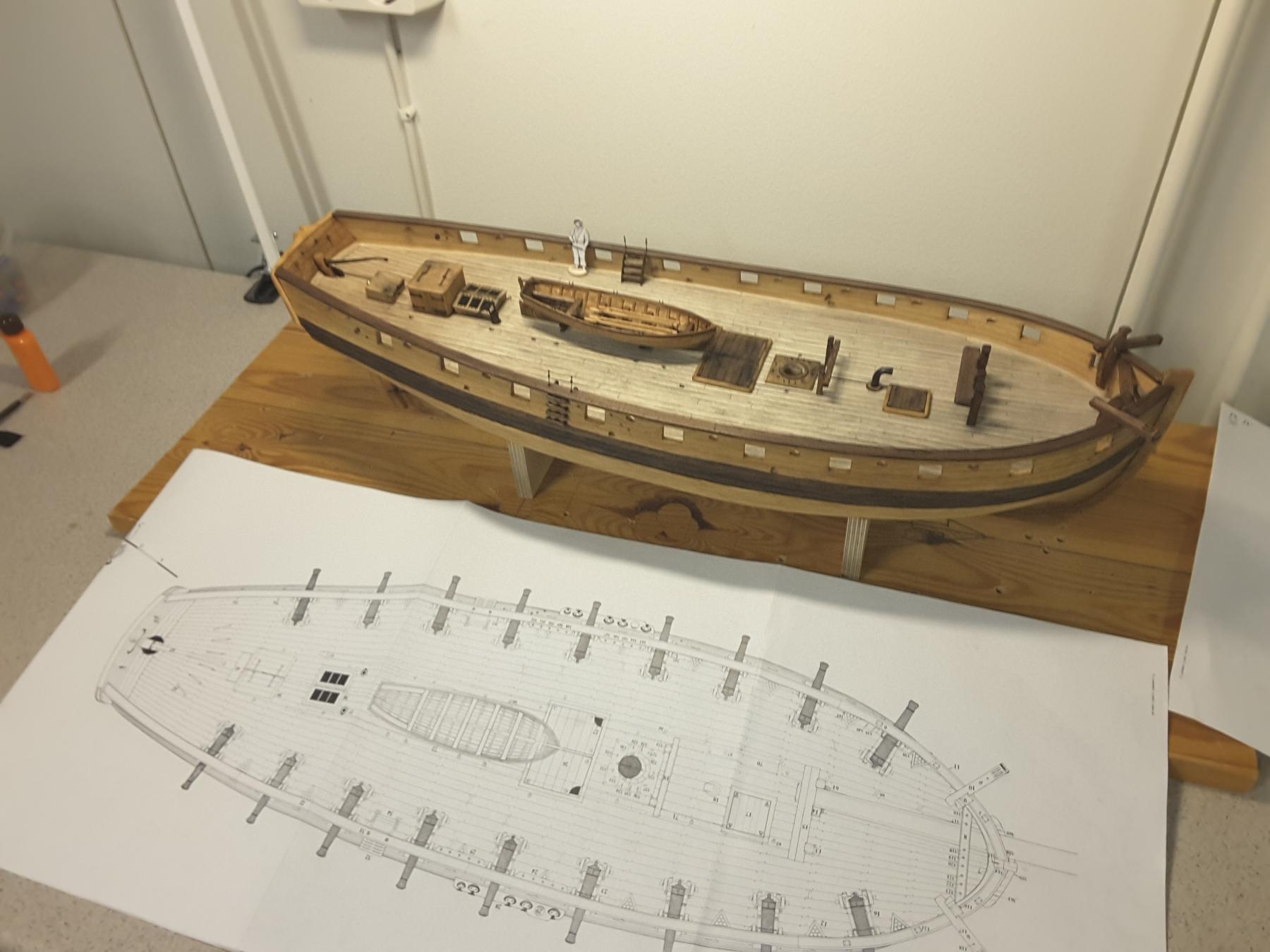
My build of Le Cerf is nearing the phase when I have to start rigging the ship's cannons. There are 16 pcs 6 pounders and 2 pcs 8 pounders on the deck, but unfortunately the plans lack completely their rigging. Because of this I wonder if any of you might give me a link or tutorial to show how these are rigged in the correct way.
-
I bought their monographie Le Cerf, which is a nice cutter of the French Navy from the end of 17. century. The package included a small book of the ship and a set of very well drawn and accurate plans with 12 sheets, everything in English. There are some discrebances in the plans, but careful studying helps understanding them and avoiding mistakes. I am very pleased with the package, and the model of Le Cerf is progressing well:
-
When considering material for my present project's sails, I have read from various tutorials that people have used silkspan. It seems however that silkspan is not any more easy to find from model shops. Instead they are suggesting to use litespan, which is widely used for aeroplane models. But is litespan same product as silkspan, and can it be used for shipmodel sails in the same manner as silkspan?
- 1 reply
-
- 2
-
-
I made my own. Needs only small pieces of 2,5 mm plywood and small screws. Works great.

- 24 replies
-
- 11
-
-
This is interesting, Aviaamator. Do you speak Finnish? We could chat somedays through Watchup. And Alexander, how on earth you are making those carvings, with chisels or rotary tools? It could be interesting to see a video of you making those masterpieces.
-
Making Rope
Moxis replied to ca.shipwright's topic in Rope Making/Ropewalks's Discussions about Rope Making
http://modelshipworld.com/index.php/topic/13234-do-it-yourself-motorized-serving-machine/ -
Carvings with a cnc router
Moxis posted a topic in CAD and 3D Modelling/Drafting Plans with Software
Having used my cnc router for years to produce 2D and 2.5D parts for my models, I have recently thought to use the machine also to make carvings for my present project. But the problem is that with my present CAD program I cannot make any 3D modelling. So the question is, where to find a modern, reasonably priced, easy to learn relief carving program. Some colleagues have suggested Autodesk`s ArtCam, but I consider it too expensive and perhaps already a bit aged. There must be more modern variants available. My machine is a 3 axis one which normally should be adequate for relief carving, but if 4th axis is necessary, it would be reasonably easy and cheap to upgrade.- 1 reply
-
- 1
-
-
Computer routers
Moxis replied to Greg the peg leg sailor's topic in Modeling tools and Workshop Equipment
Very interesting topic again. I have many years used my 3 axis CNC router, but only for 2D and 2.5D tasks. To build fourth axis is very simple, and doesn't cost very much, but the threshold is to buy and learn to use some 3D cad program. So I would like to ask you guys, which CAD programs are you using with your routers?