HOLIDAY DONATION DRIVE - SUPPORT MSW - DO YOUR PART TO KEEP THIS GREAT FORUM GOING! (Only 20 donations so far - C'mon guys!)
×


Gaetan Bordeleau
-
Posts
1,307 -
Joined
-
Last visited
Content Type
Profiles
Forums
Gallery
Events
Everything posted by Gaetan Bordeleau
-
 I did correct the spacers thickness on 1 section of about 20 frames. I could fit the last spacer, but strength must be use, and this would be an error, not to correct it, because this induce strength could bend some frames. Roughly 1 spacer .215’’/ 20 frames : about .010’’ less : .215’’- .01 ‘’: .205’’ the new thickness. For 60 frames, 60 times glue thickness changes the overall thickness. It is very difficult to do 60 frames with their components to exactly the same thickness at 001’’ close. Theoretical and practical thickness of the entire sandwich are different. On 8 feet long, overall thickness was 1 spacer too thick , glue thickness is at least partially responsible and I am for the rest and even more. Even if I could be precise at .001'', I would still have to subtract 60 frames, double thickness + 1 spacer: 60 X 3: 180 glue thickness probably at least .180''
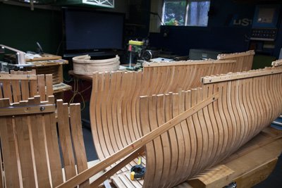
-
There is no good or bad answers in choosing cutter or rotary tool, it remains a personal choice a matter of preferences. Which ones will produce cleaner edges, gives more nerve to the work? Only knife or both? Here is an example of rotary work : https://modelshipworld.com/index.php?/topic/15340-74-guns-ship-by-gaetan-bordeleau-124/&page=9
- 208 replies
-
- 4
-

-
- le soleil royal
- 104 guns
- (and 2 more)
-
Roter Löwe 1597 by Ondras71
Gaetan Bordeleau replied to Ondras71's topic in - Build logs for subjects built 1501 - 1750
I built this kit some 30 years ago with this book: Risse von Schiffen des 16. und 17. Jahrhunderts -
There was a bow in the keel, about 1/8 inch… too much pressure, I guess. Off the spacers, rechecked 5 frames still not glued, keel is also in 2 parts. And the bow disappeared, replaced spacers and lucky I am.
-
Neko, you built miniature cutters and you show us that you will have the necessary skill to produce nice carvings. Sculpture is an art you can learn, but you need to have basics talents. I would say that the most important tool would be the proportions. The last ones I did were for the Fleuron which also appeared in this forum. If I could suggest 1 helping hint for carving, it would be to try rotary burrs and for the smallest ones, dental burrs. There is a learning curves in using tools. In carving, we begin with knives but a knife is harder to control than a rotary burr. You need to exercise strength and control his dosage. With rotary burs... you need no strength to control it, the tool has the power and you concentrate all your talent on the carving.
- 208 replies
-
- 9
-
-
- le soleil royal
- 104 guns
- (and 2 more)
-
Thank you Pat Carabrente, I forgot about the thickness off the spacers which must be few millimeters under the theoretical value which would be too stiff. It is better not to calculate but it is better to try a thi.ckness which works easily
-
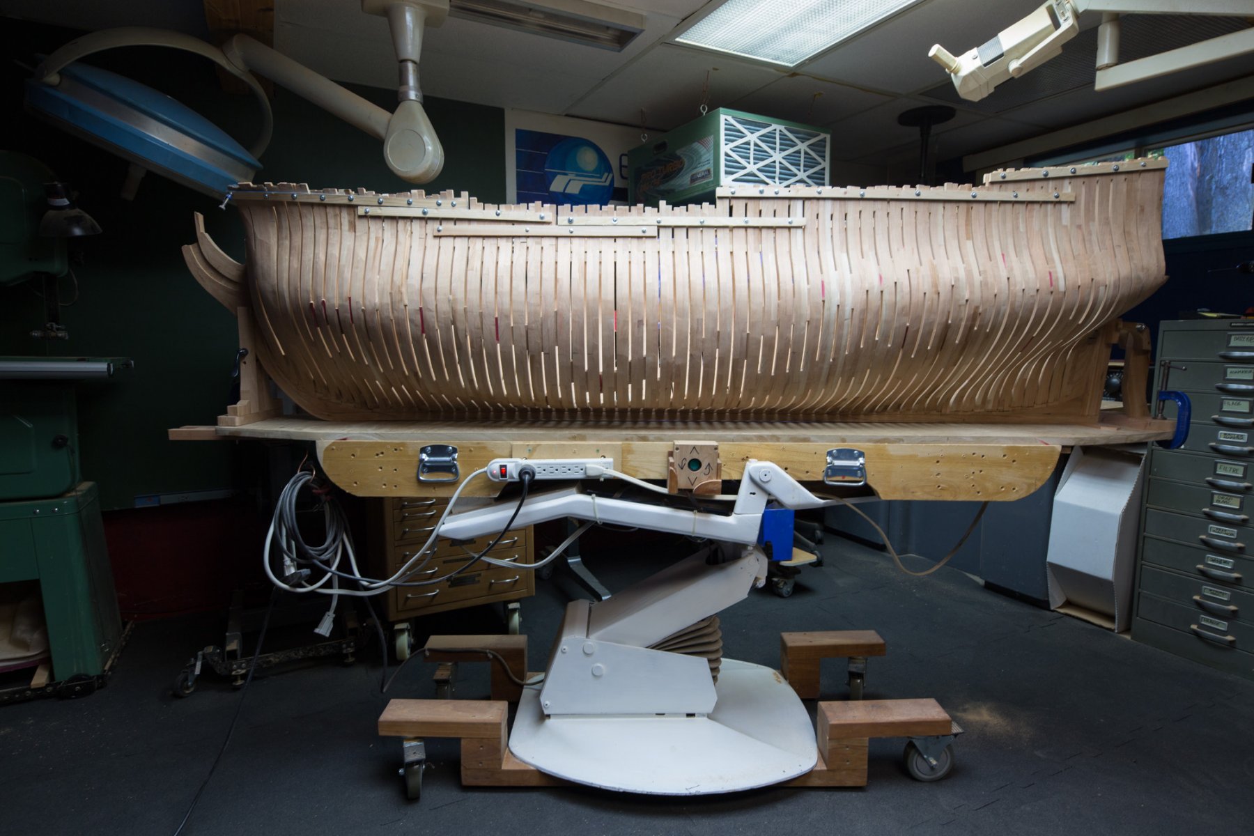
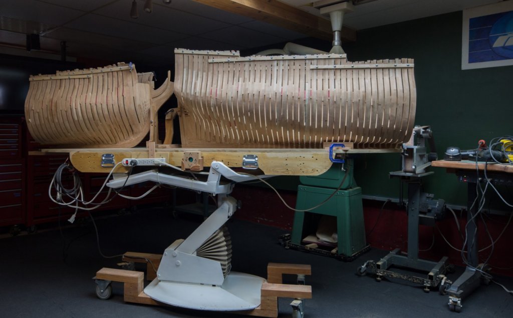
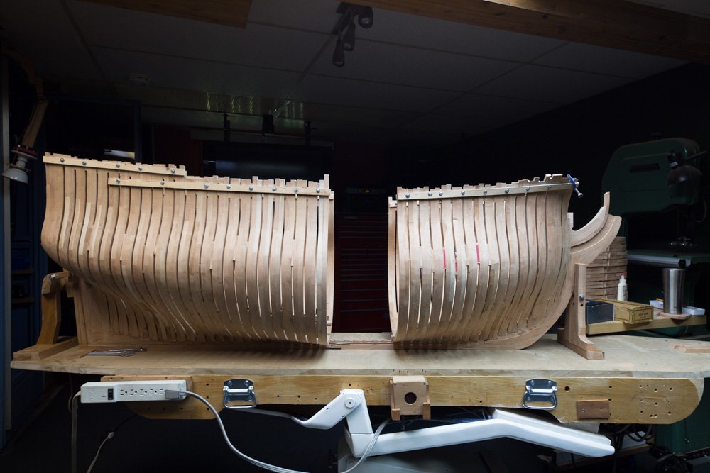
Hi noel_colledge, The previous 74 guns 1/24 weighed 130 pounds. To move it, you need wheel as big as you can, the bigger, the easier, and I also a lifting table with a cylinder. Good morning Carabrente, When things are done correctly fillers inserts easily without pressure. Fillers are all the same thickness at 95% and some are thicker. The idea is the same as a pressure cooker, you need a valve to release pressure or else it will explode. The best things as others clearly well demonstrated is to a have a spacer not glued at every 4 to 6 frames.
-
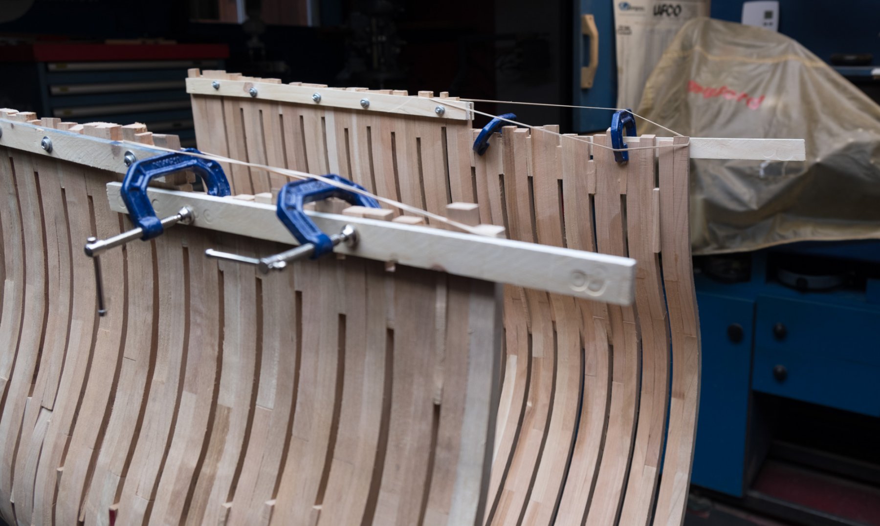
Hi Dave, Spacers are temporary, they hold by pressure only, installed from 1 end toward mid ship
-
Impressive results and very nice drawings, Marc. How far will go with this model, will you do all the carving?
- 208 replies
-
- 2
-
-
- le soleil royal
- 104 guns
- (and 2 more)
-
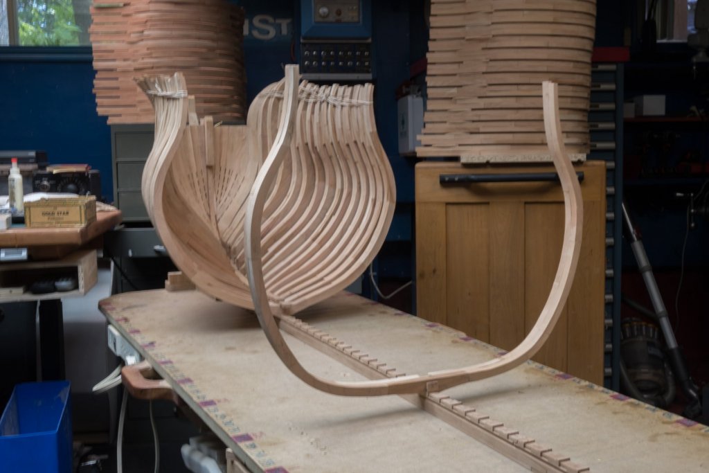
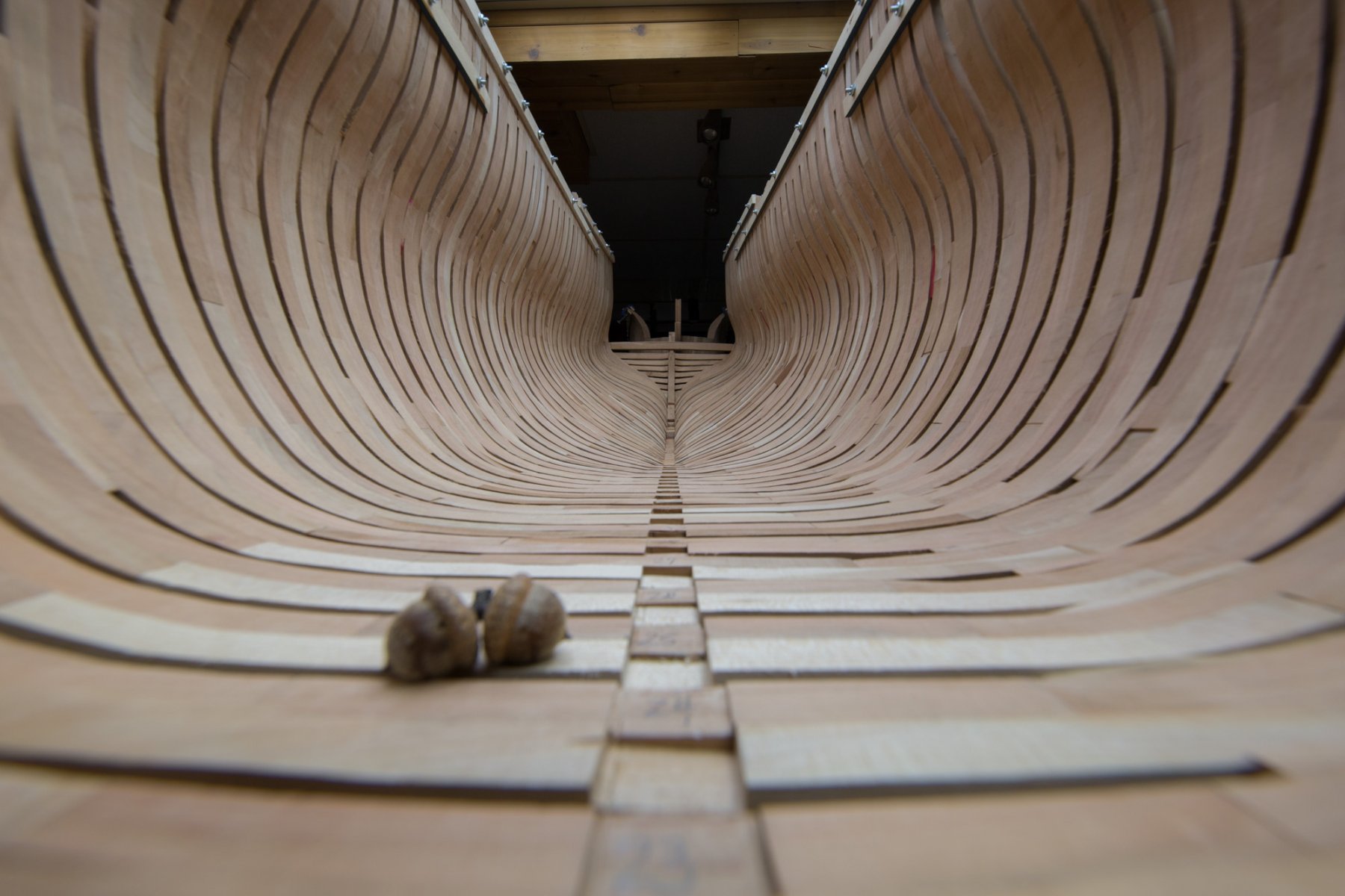
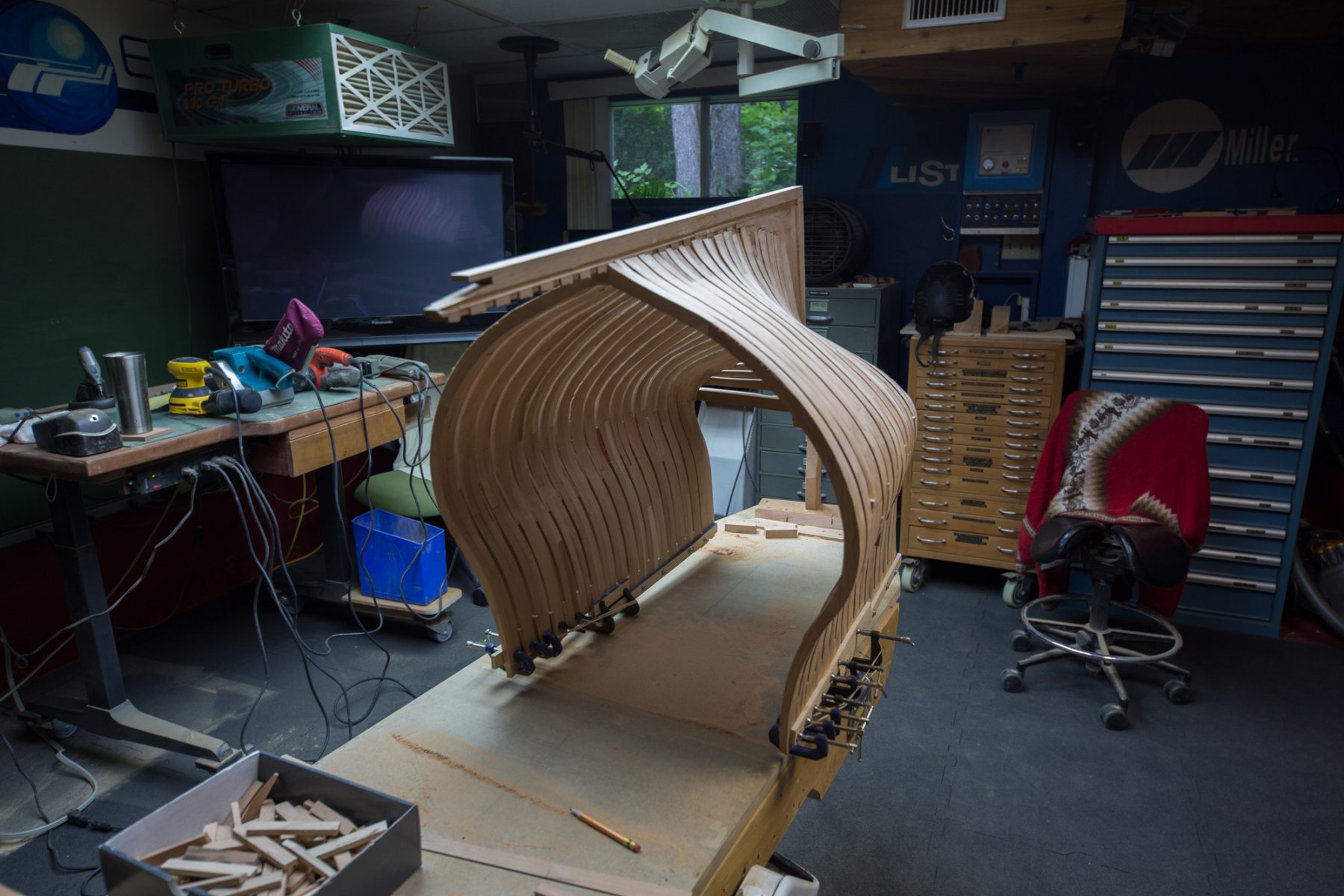
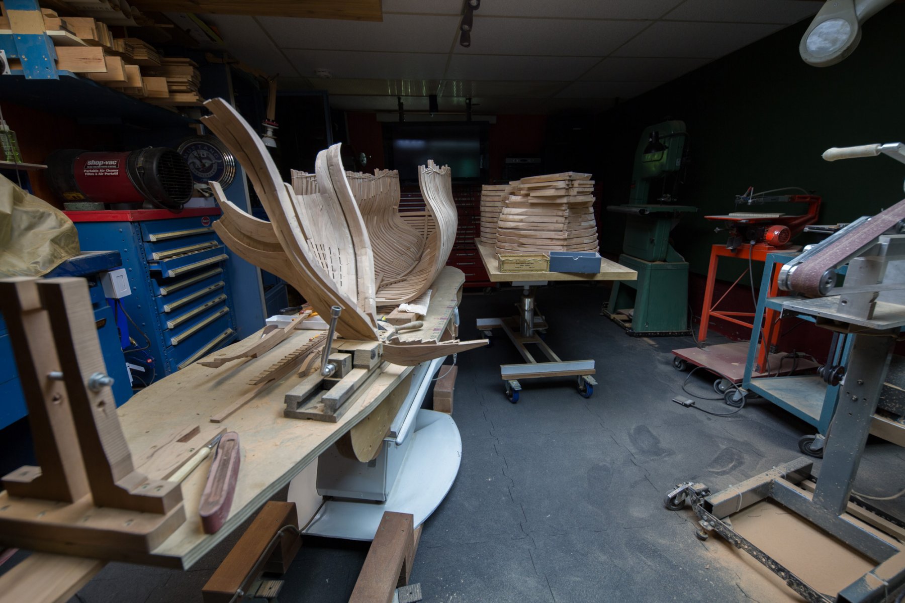
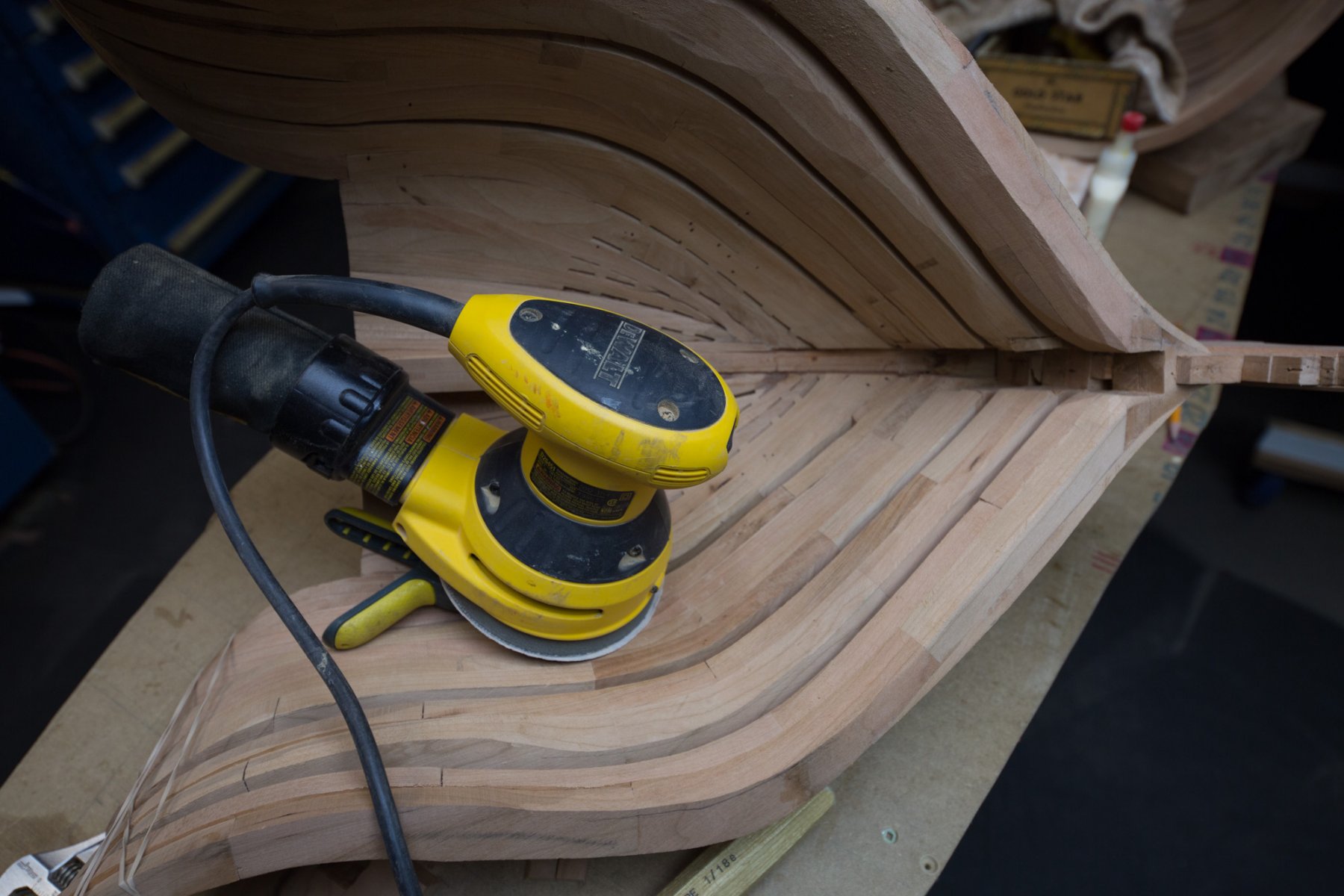
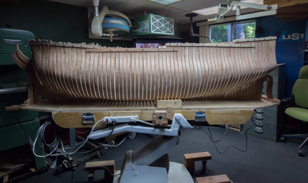
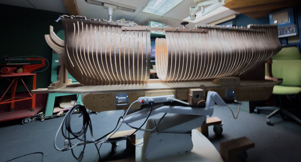
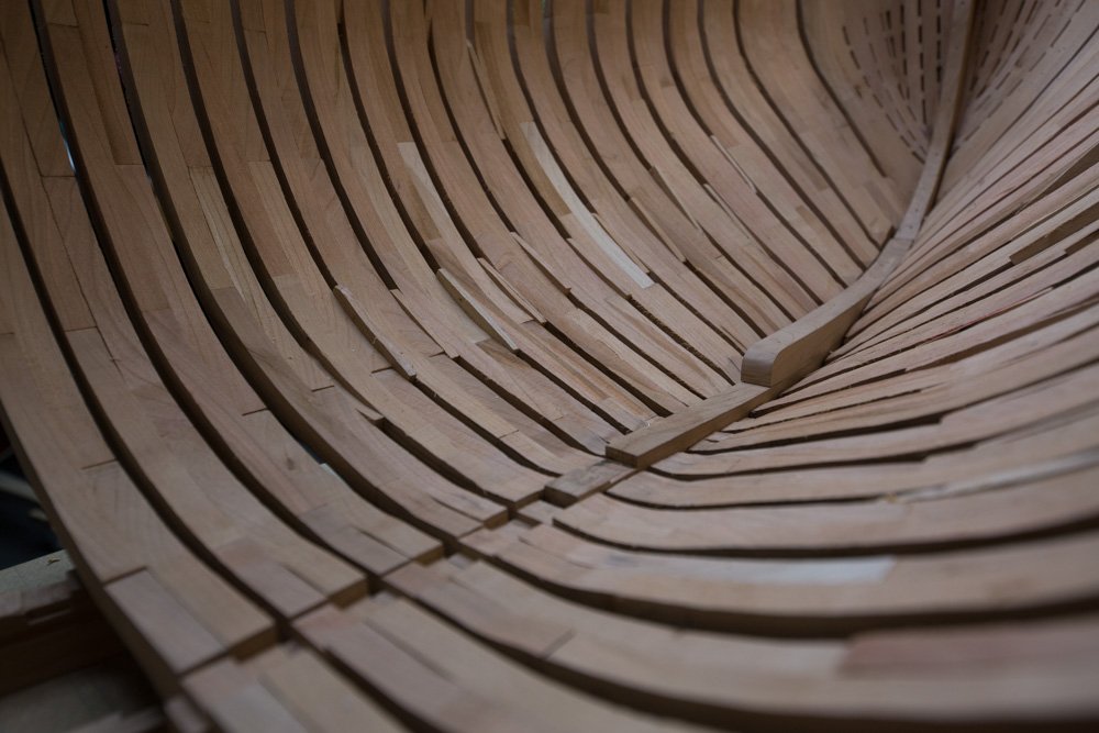
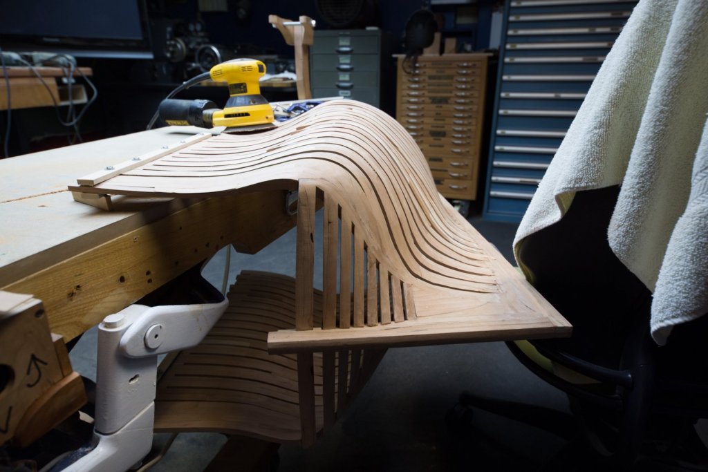
6 months of work and the last one, sanding only. Vibrations transfer to the frames while sanding, especially with the orbital sander. One way to avoid this is to insert spacers between each frames. This way, each frame does not resonate as when we pinch a violin cord but all the frames become a whole unit and vibrations disperses in the whole assembly.


-
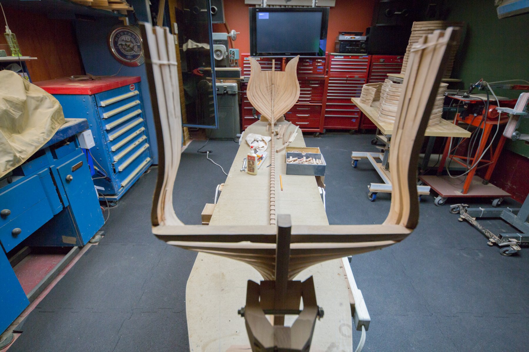
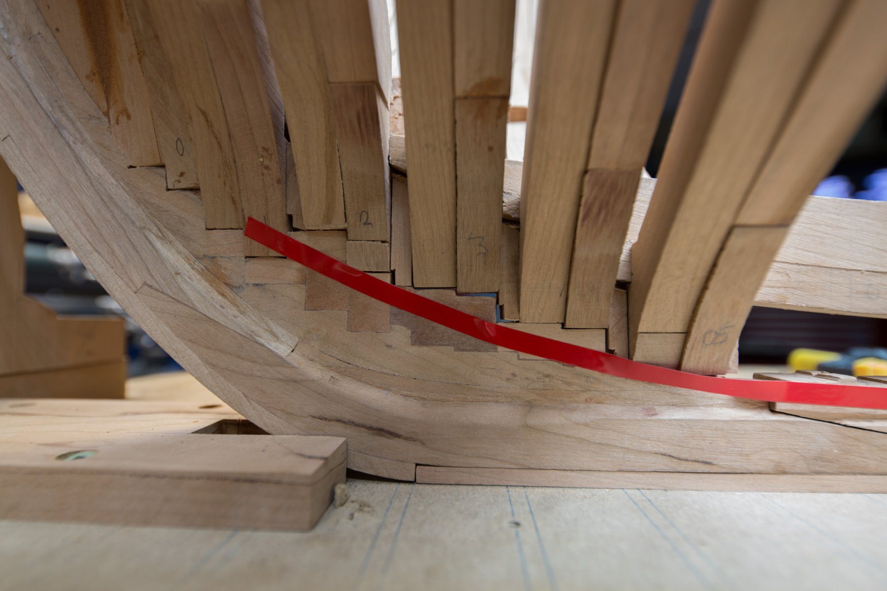
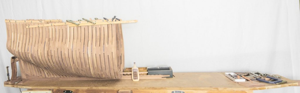
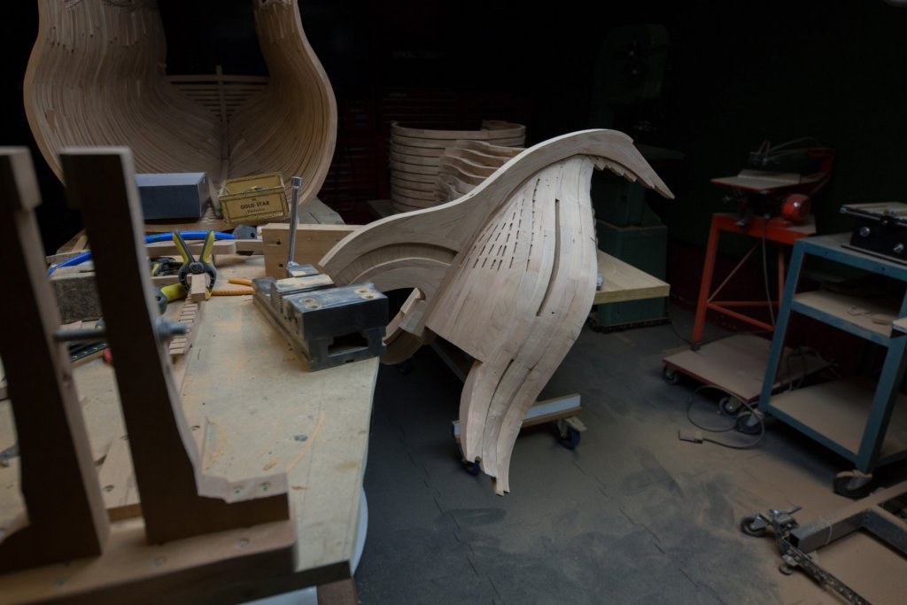
What would like the shorten version of a 74, something like this.
-
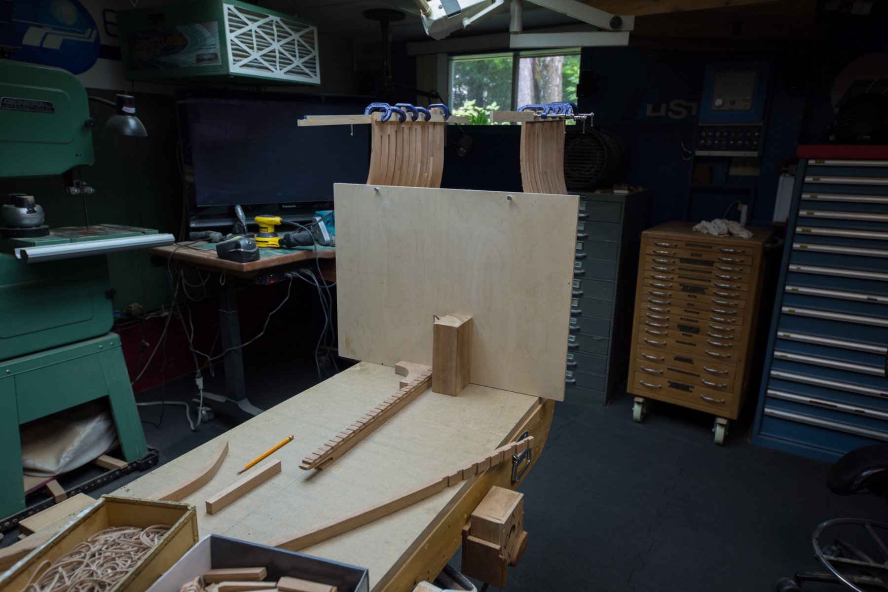
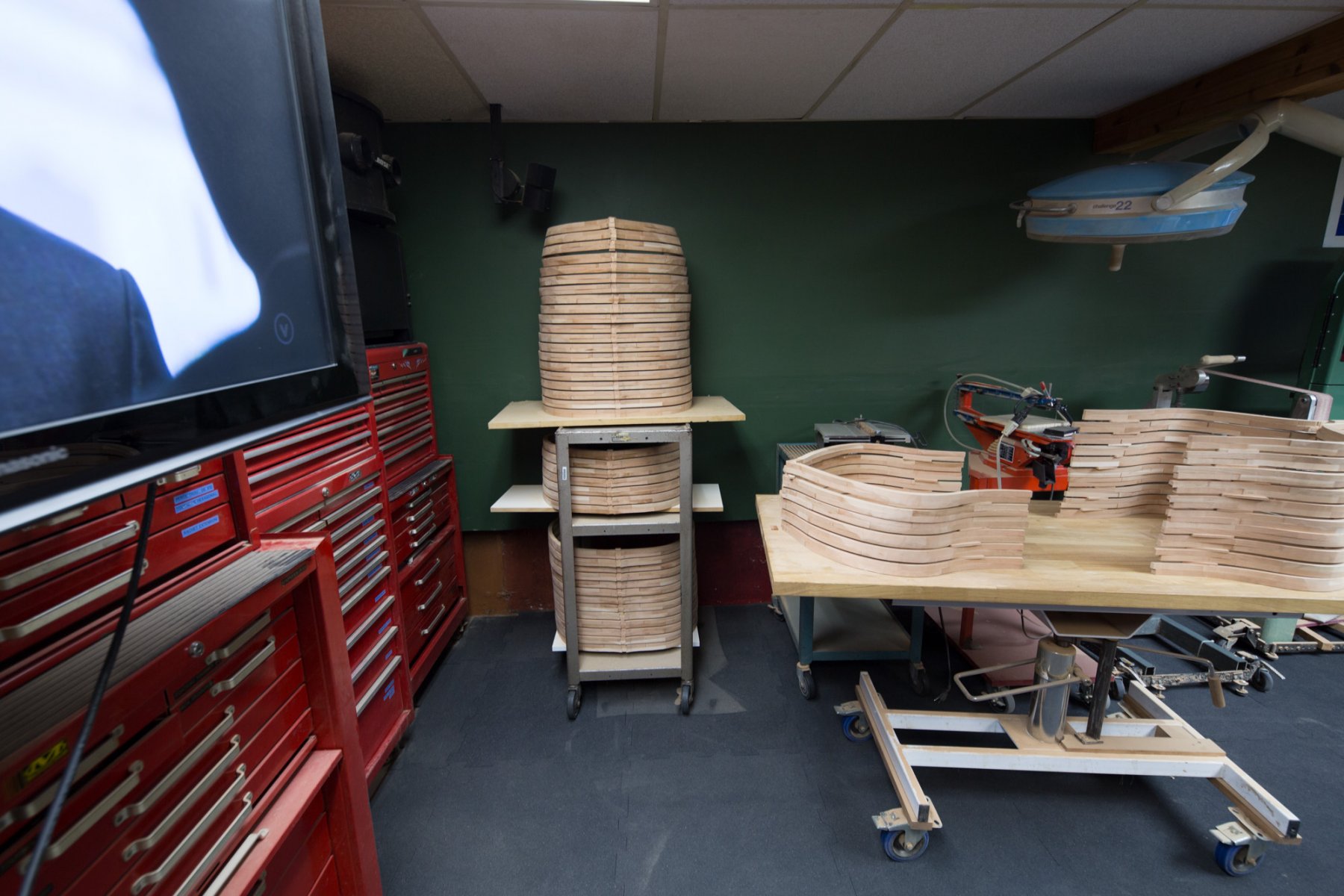
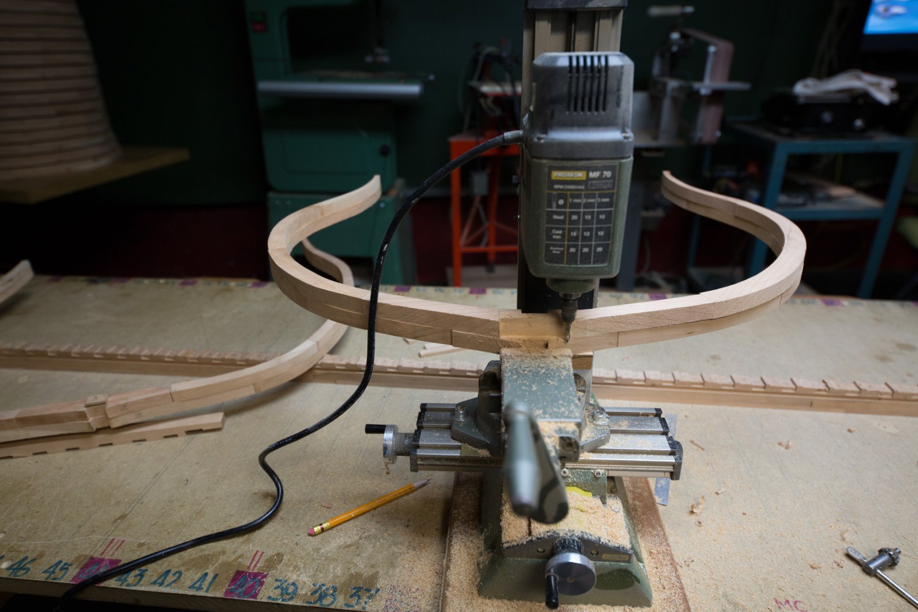
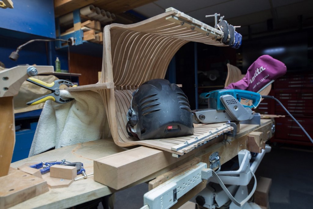
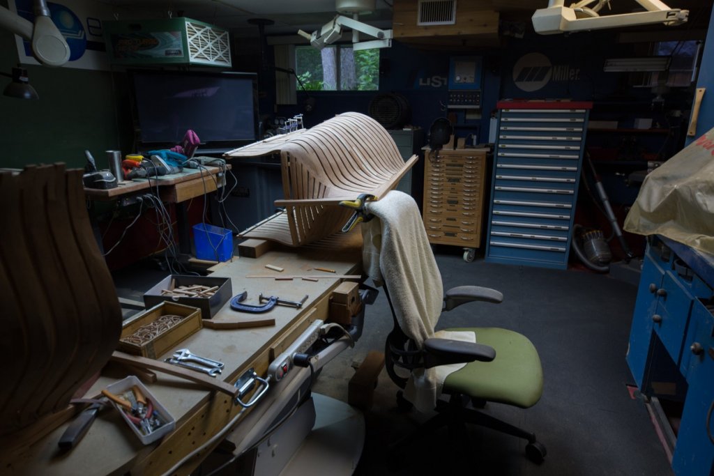
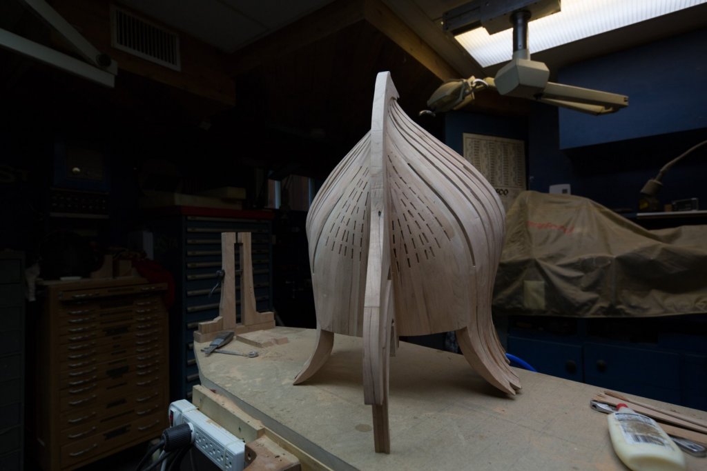
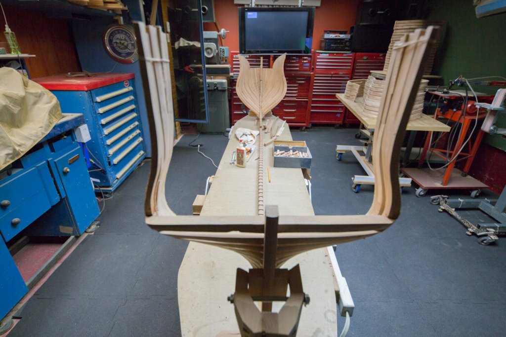
On the pictures, we see the control plank for perpendicularity in 2 ways. Others are sanding setups for all the curves. The main 2 ways to assemble frames to the keel use a jig to align the frames between them: - a plank supports the frame contour. Frames are assembled upside down as Hahn did or reverse. -Frames alignment can also be done another way; with just a baguette to align frames. This baguette moves the same way as the assembly goes. The other part of this assembly is the frame sanding. Again, there are 2 ways to do the sanding : the easy way and the hard way. When a jig is used to support frames, most of the sanding will be done after gluing all the frames and after taking the frames out of the mold. This method is much more restrictive because the accessibility to all the frame parts is restricted when it is in the mold. The other method has the advantage of ease of maneuverability in all the ways you need. Sanding is much more easy, at least for a model at 1/24 scale. Part which need to be sanded can easily be position. Also another very important part : height adjusting table. Working at the good height is often the difference between holding a heavy part easily or with much difficulty.


-
Myth or reality? Ebony does not glue well: myth, it does glue as well as any other wood. Every dust wood is bad for lungs with the years. One particularity of ebony dust, it is probably the finest dust, it is so fine it can inlays skin hand pores.
-
Hi Karl, Chris is right: with the practice of the first one, the result of the second one will be a masterpiece.
-
As an example, here is a photo of a limber way on a ship. The notch does not need to be very big. http://www.atlasponant.fr/fiche/icono/Site/056KER001/#3 The building plank was 24 inches wide. Reduced it to 19 inches. It is now possible to work even closer to the work.


-
Hi GD, What would that look like in an image especially at the extremities?
-
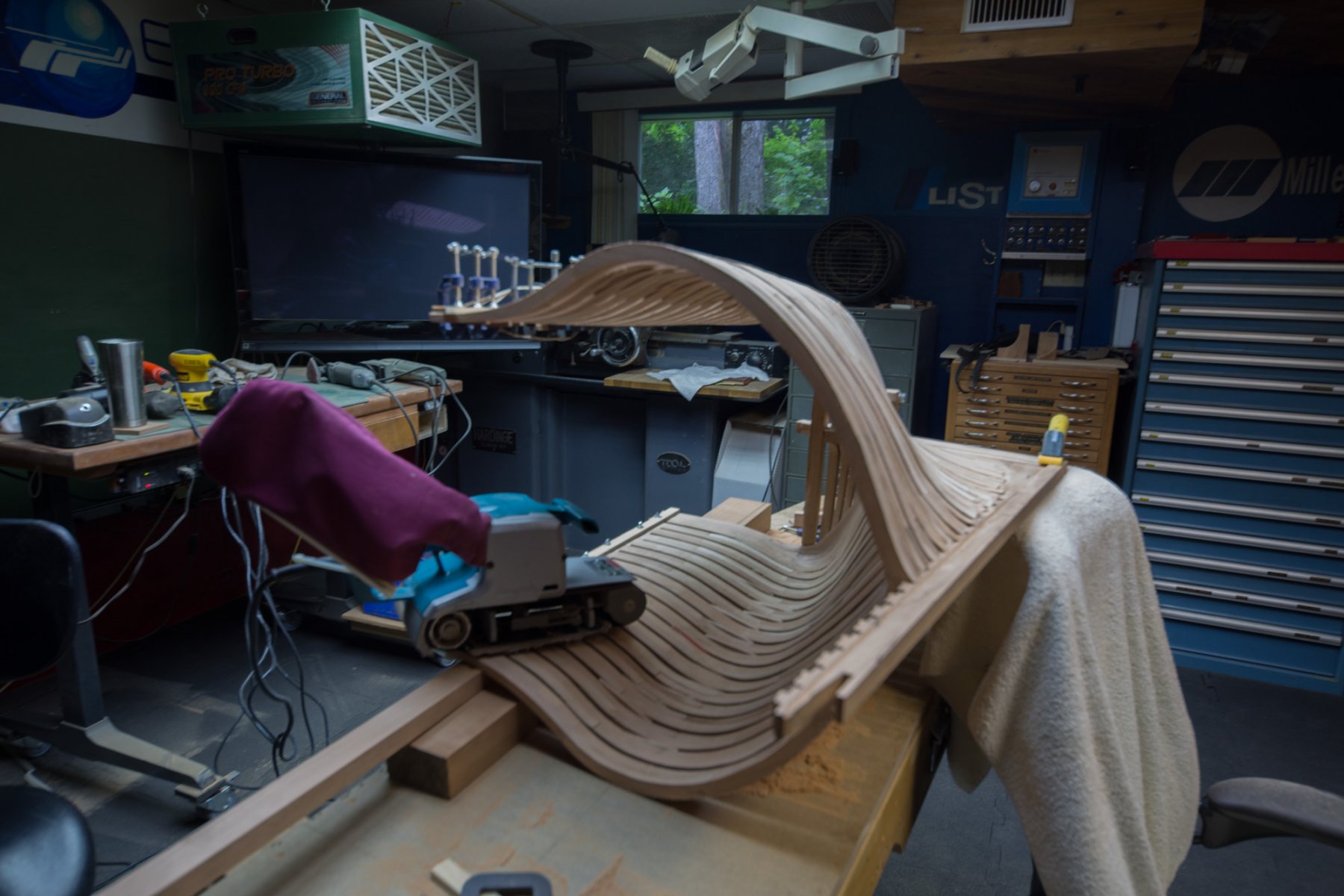
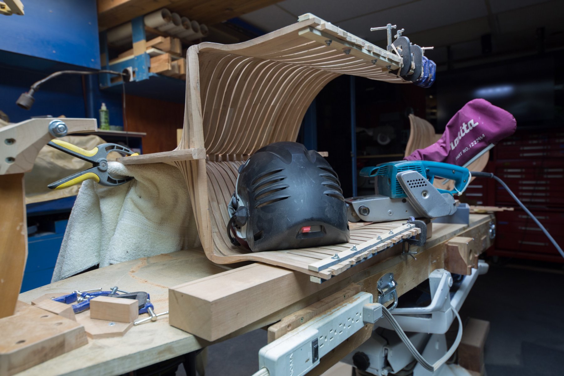
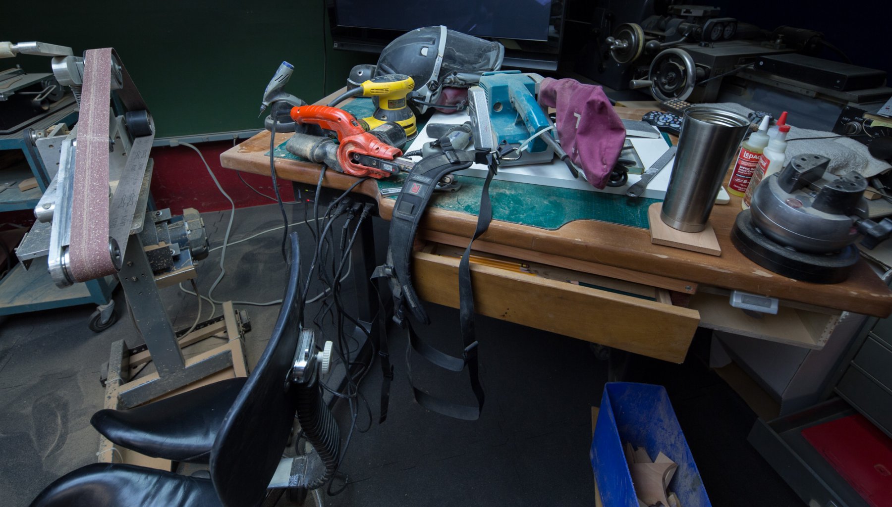
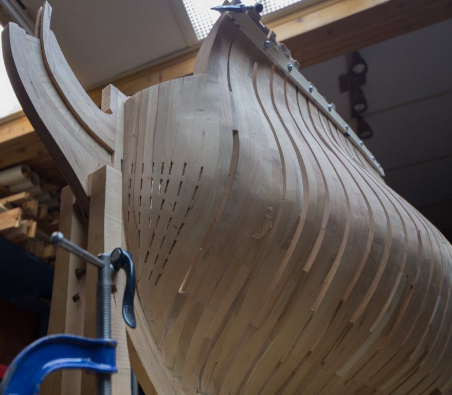
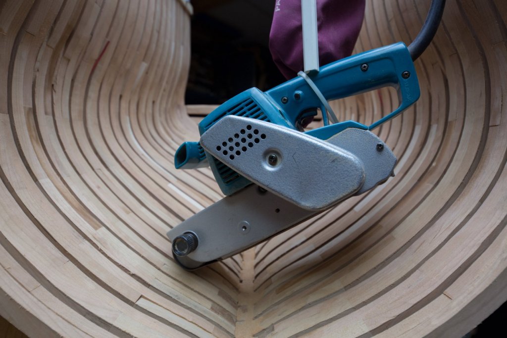
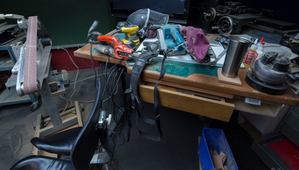
Sanding spree has began. One question comes back often, how to sand inside curve; with around orbital sander. To reduce the weight of the belt sander 1 strap is added to support the weight. This is a camera belt recycled as belt sander belt.


-
ancre Le Fleuron 1729 by rekon54 - 1:24
Gaetan Bordeleau replied to rekon54's topic in - Build logs for subjects built 1501 - 1750
Welcome back Giorgio! -
There are decisions which must be taken on the construction site. I think this is a good example. I will put the water collecting line just under the frames for and aft. Gravity will do the rest.

-
The idea is not to create wooden pocket which could accumulate water and have the wood to rotten. 2 ways to solve the problem: make a hole in the bottom of the pocket, fore and aft ‘’keel’’ would be 100% wood with no air pocket. Naturally, all wood joints are covered with tar. The disadvantage of this last solution, more wood, heavier ship.
-
Many minds together will always be stronger than only one. I think it would be safe to assume that the covered area would be only in the lower part as in picture one. there is something wrong in the second picture. To go through the limber hole channel water must be at least 2-3 feet high before being able to reach the limber hole. Water accumulation in that lower area would probably conduct to rotten wood.

-
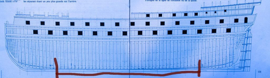
Picture already shown by Hjx; limber hole at the aft. I do not see how the water harvested by the limber hole would go so deep! Is it necessary to go so far with this line?
-
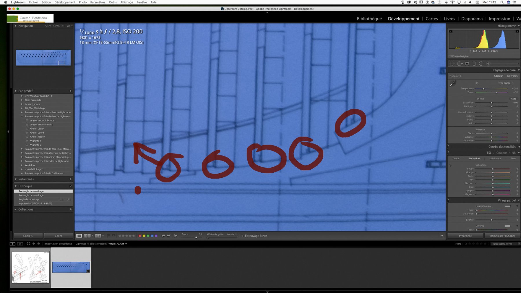
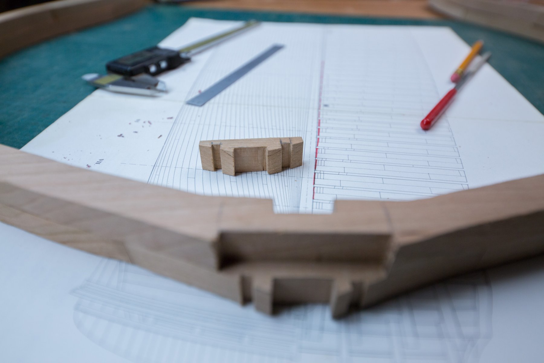
Another try on the other side to prevent rotten wood. In the background, the plan showing a notch each side of the keel for the water flow. The notches, I think are drawn on this plan only. This is the kind of reason when a detail is shown on 1 plan only, it can difficult to visualize the other dimensions. This is in this kind of reason why I would like to see a 3D keel included with the drawings.


-
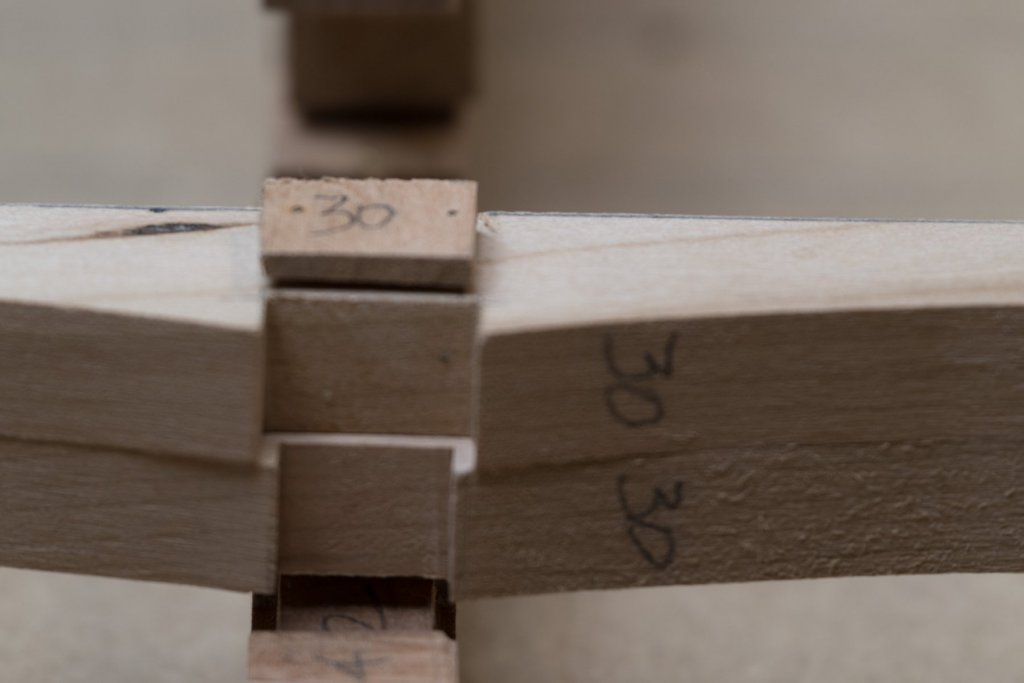
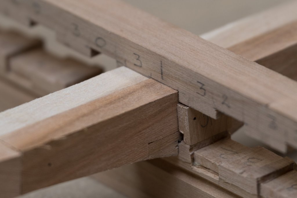
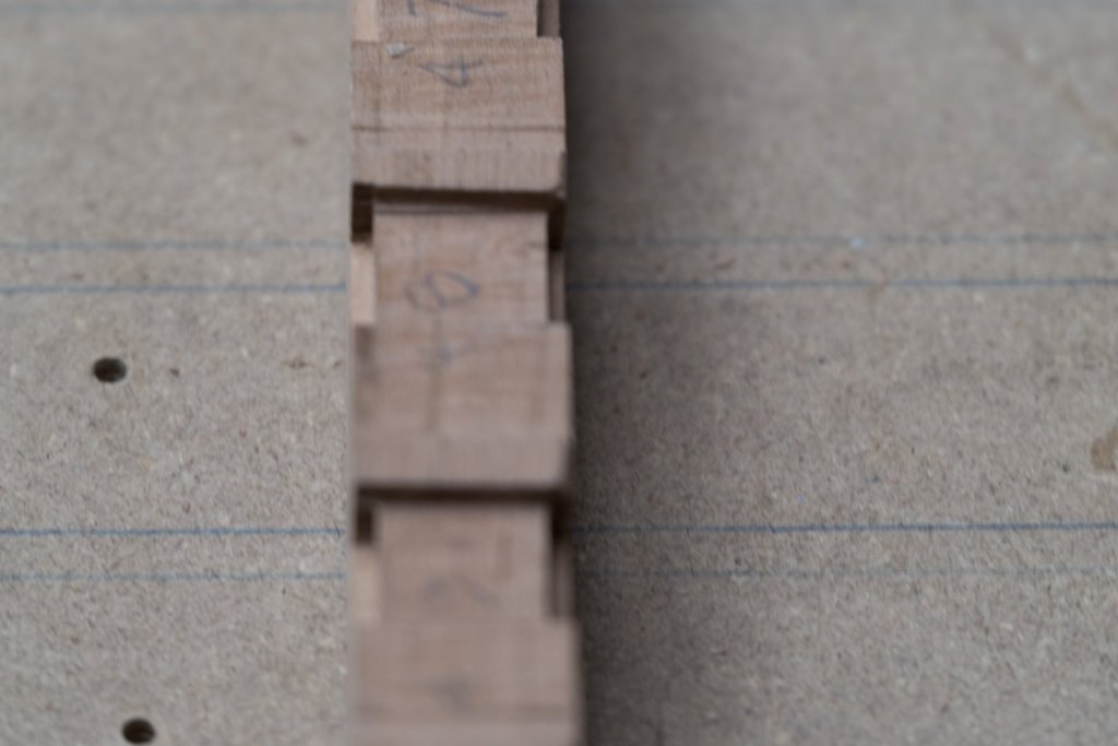
So roughly for 60 frames minus frames of both end, roughly 35 frames at 1 by frame would be about 35 which is much less than I thought..
-
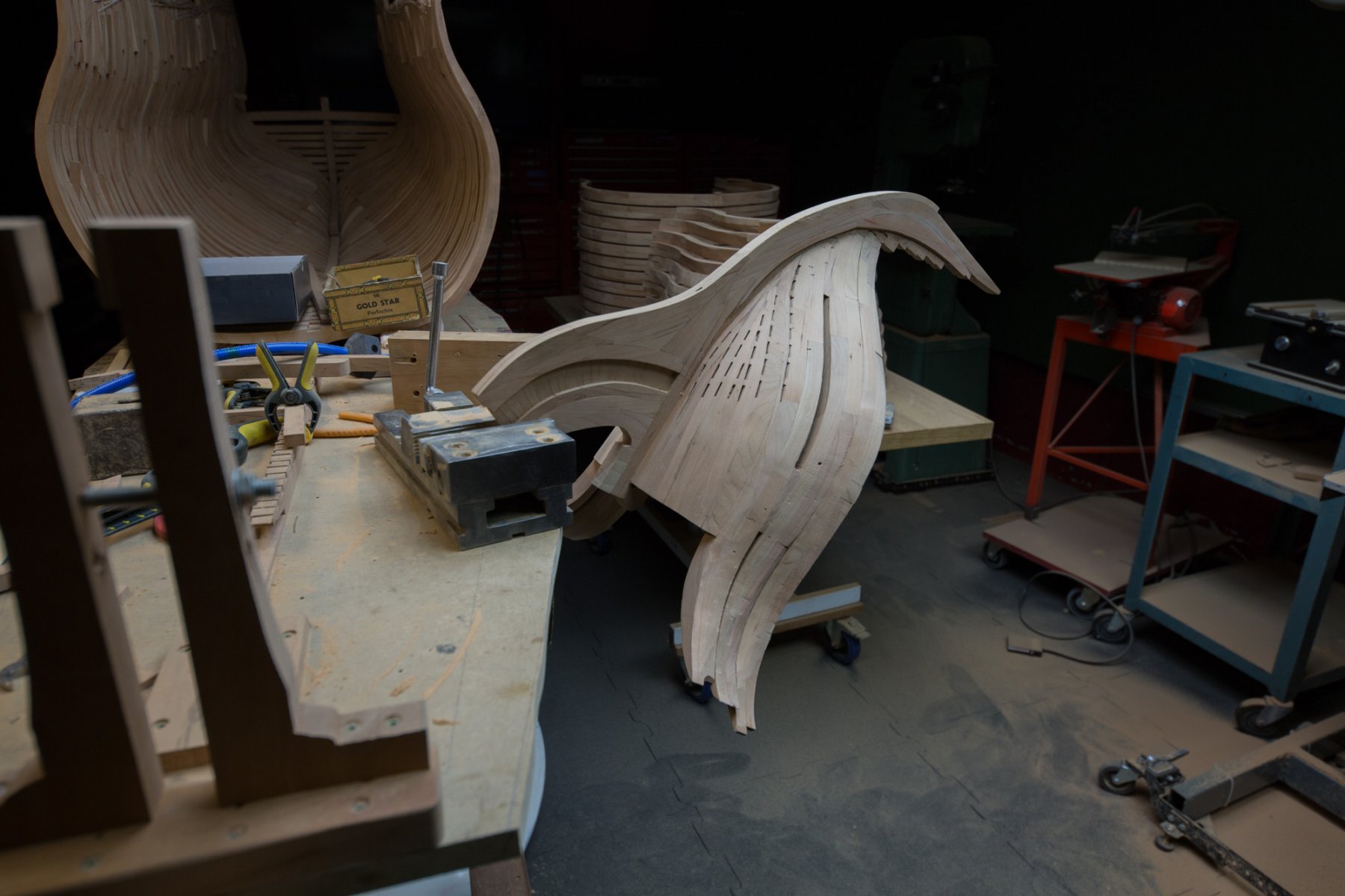
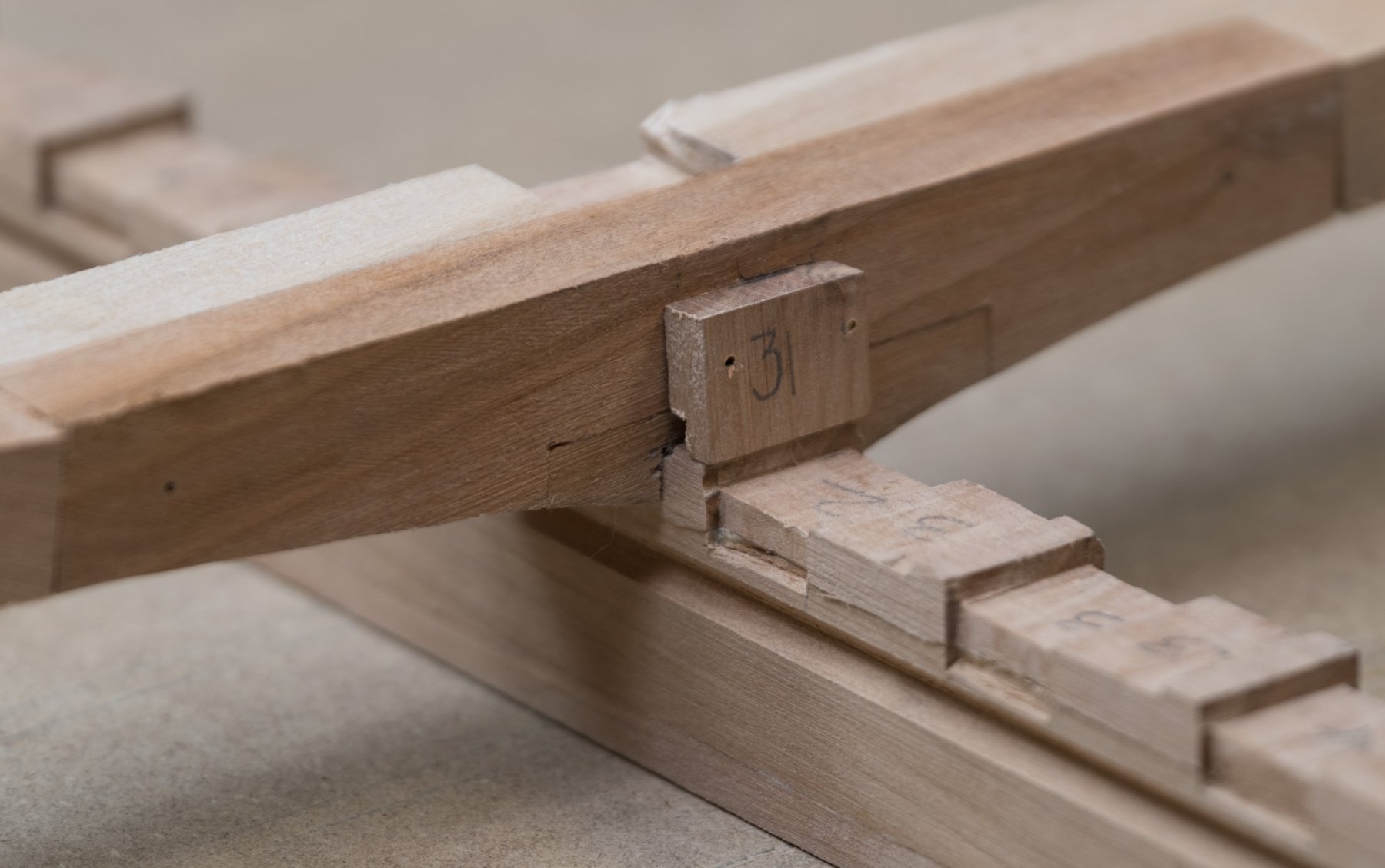
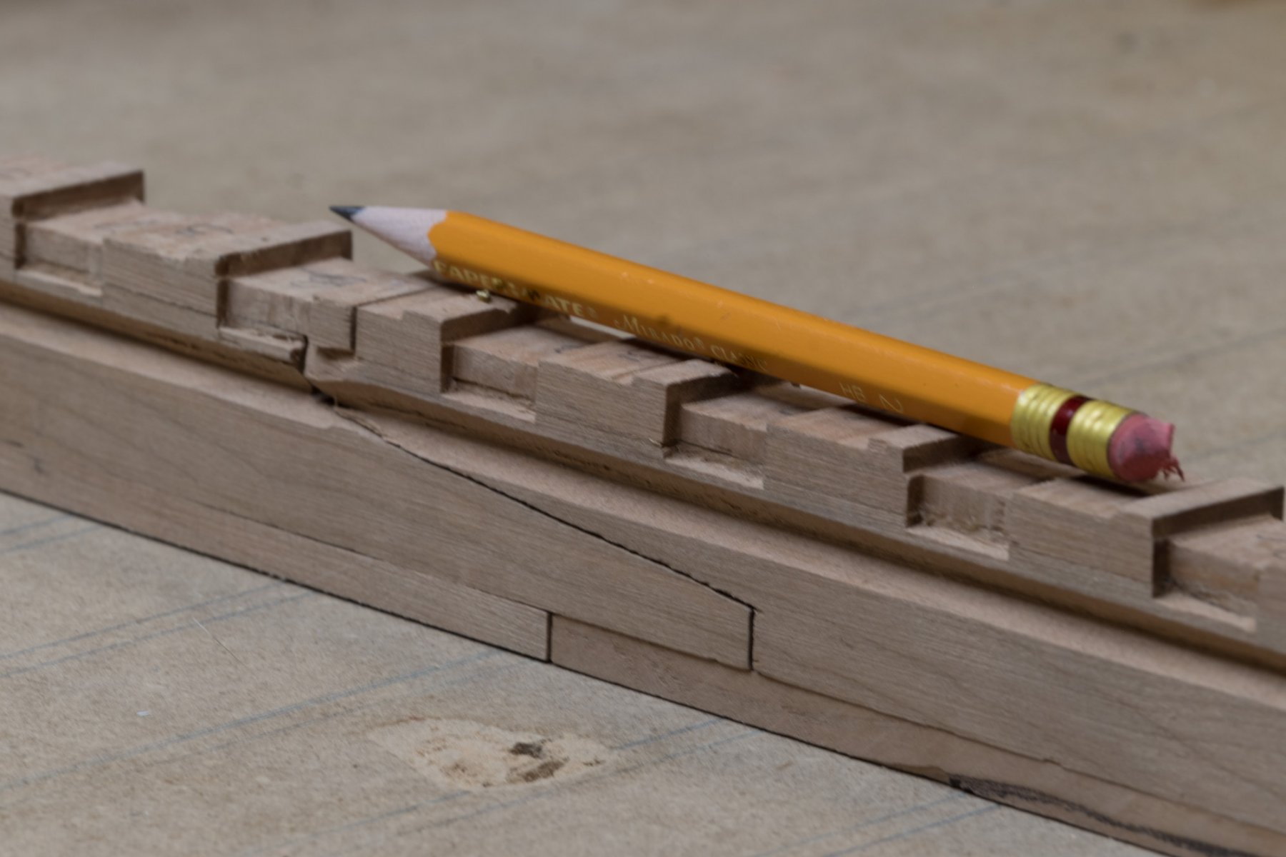
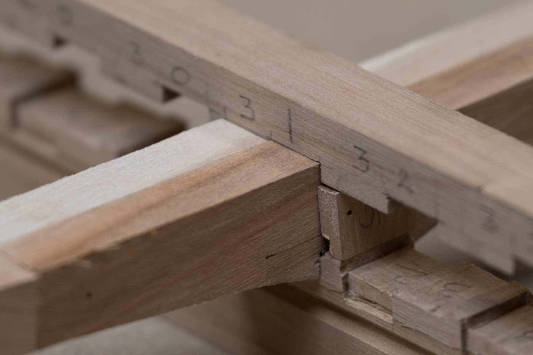
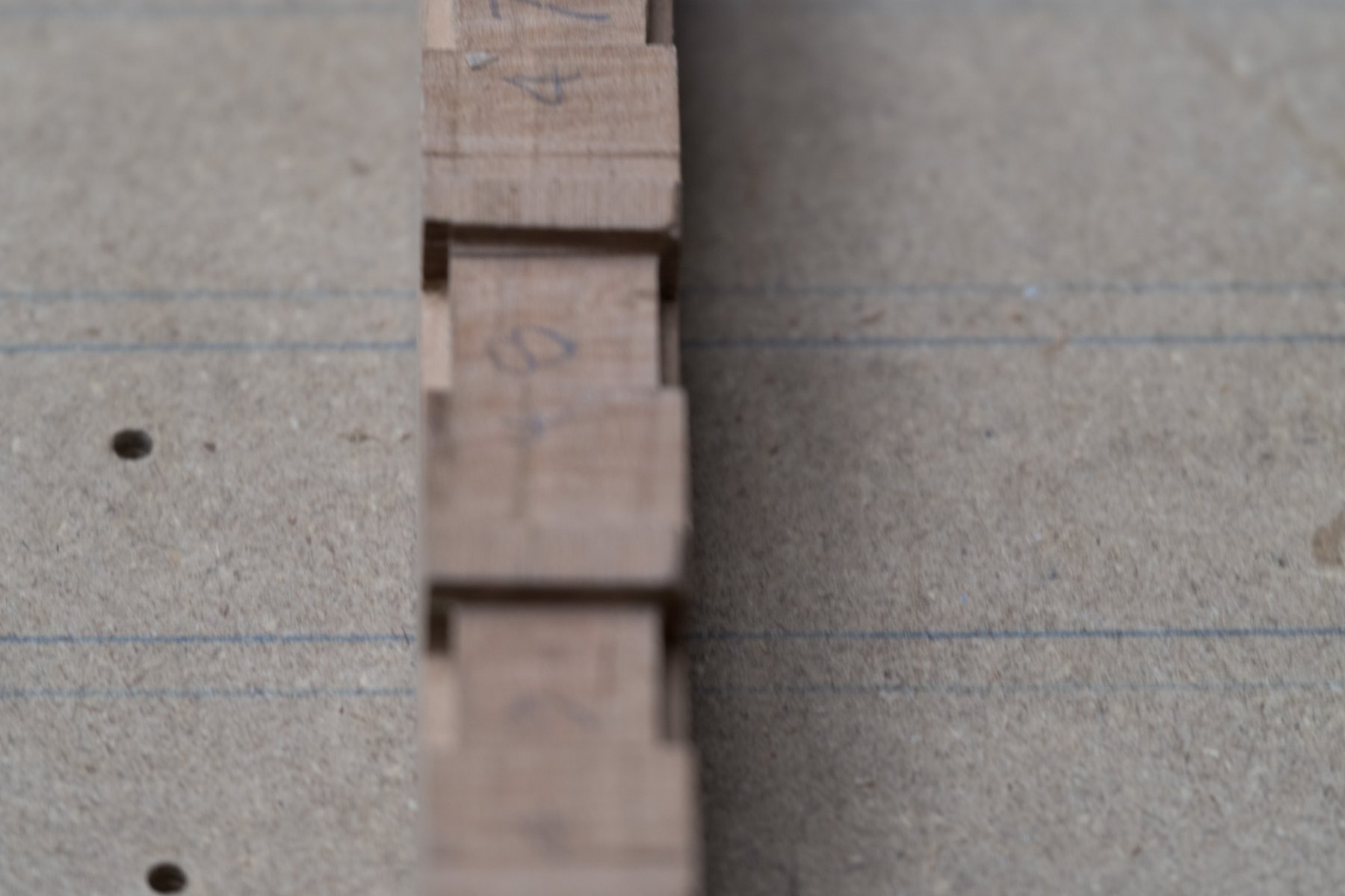
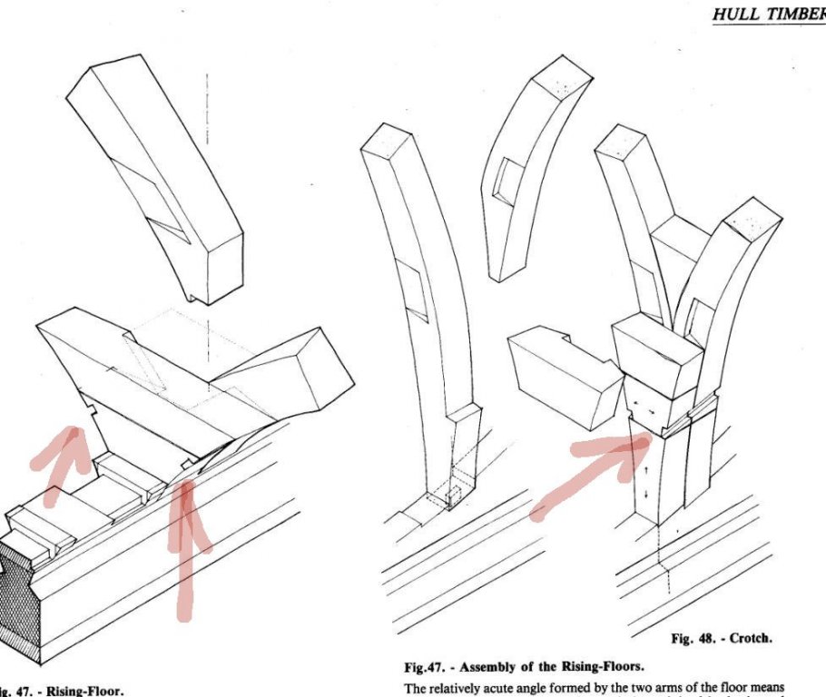
Here is the idea of how frames join to the keel. The kind of filler added under the frame was to save wood. I tried some to see what it look like. This is the kind of details which disappears when all the frames are assembled. With this carpentry, a frame holds solidly on the keel.