


Jason Builder
-
Posts
219 -
Joined
-
Last visited
Content Type
Profiles
Forums
Gallery
Events
Posts posted by Jason Builder
-
-
Greetings!
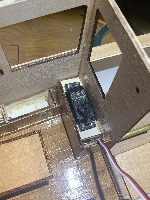
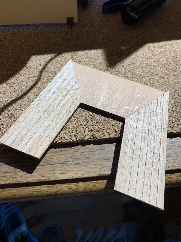
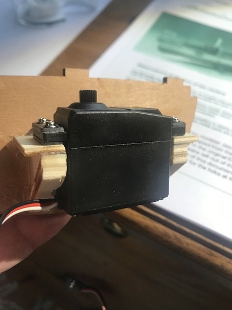
I measured the height and the offset-from-centerline of the forward/reverse/rpm valve on the steam engine, and I marked this location on the cabin front wall where the actuating rod will pass through to connect the valve to the servo housed in the cabin. I made thicker/stouter servo mounting blocks out of laminated pieces of plywood. As this servo can only be removed vertically, I notched out the servo bracket in order to allow the wires to pull up vertically through the brackets. I glued the brackets in place with a thick coat of epoxy.
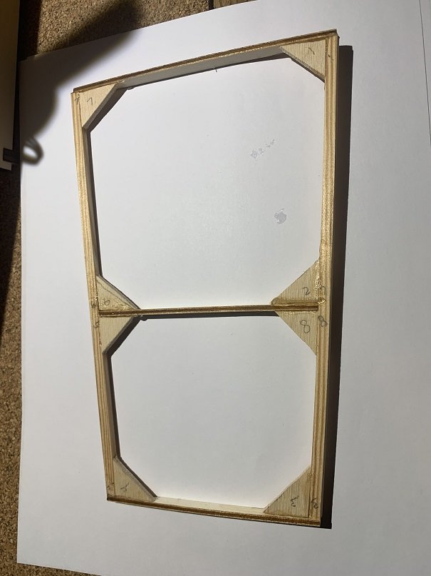
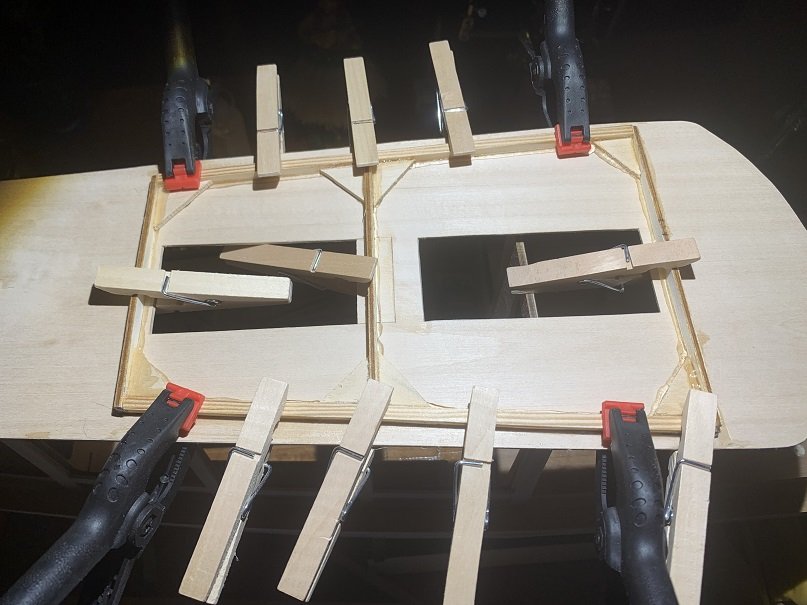
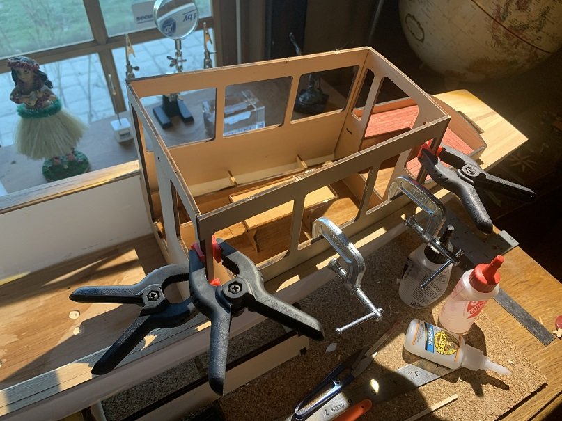
Today I also glued in gussets in the roof frame (I couldn't find the little gussets that came with the kit, so I cut my own). I am pleased with how snug the frame sets into the cabin sides. Then I located and glued the frame to the cabin top itself. There is a slight arch so I made sure I sanded a nice fair surface on the top of the frame before this final gluing operation.
- GrandpaPhil, schooner and mtaylor
-
 3
3
-
Hi Jo,
Have fun building the Arnanes! I built that kit in 2015 and really enjoyed it. When I saw that you were building it I was reminded that I never posted a finished model album in the gallery, so I just did that. When I was building the kit I researched this type of boat and found that the ship the model is based on was refurbished and is still sailing; she is called the Johanna and you can look at pictures of it for ideas.
https://www.mmtours.fo/product/sailboat-johanna/
Enjoy the project!
Jason
- SigEp Ziggy, SHIPSCAT, lmagna and 1 other
-
4
-
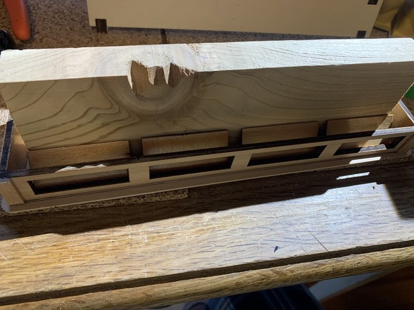
Good Morning Again! With this post I will be all caught up to where the model is as of today. This represents the progress from January to the end of November (slow progress, I know). I varnished the louvres that are installed in the cabin top vent box, and also varnished the interior of the vent box itself. Then I glued the louvres in place. I set a 3/4" board down the middle and just leaned the louvres up against it so that they are all aligned. I also trimmed out the forward cabin door. I bought some functioning brass hinges from Micromark that I will use to hang this door.
- schooner, GrandpaPhil and mtaylor
-
3
-
The roof assembly is removable on the Alexandra, providing access to electronics which are housed under the seats and in the cabinetry of the cabin. I applied electrical tape to the interior edges of the cabin sides and then glued the roof frames snug in place. The roof is glued to this frame work, and then the whole roof/frame assembly can be pressed into place and removed if needed.
- GrandpaPhil, mtaylor and schooner
-
3
-
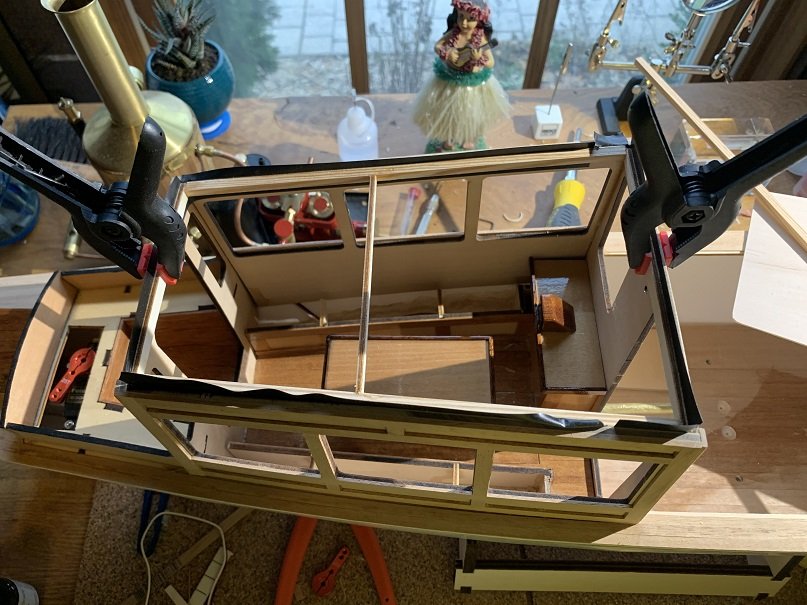
Hello Model Ship Builders!
Here are the cabin sides going up. I dry fit everything first; needed to trim back the seat-top support brackets a bit in order to set the cabin sides down far enough. These are epoxied into place. I also glued the cabin roof vent box together and added some trim to it. I trimmed out the cabin exterior with mahagony strips and also squared the windows (which have rounded corners in the stock design). At this point I made the largest variation to the stock design; I made a roof that extends forward of the cabin with a large forward radius, and the roof also extends aft to the stern. The stock roof is the size of the cabin itself with minimal overhangs, which appears to be quite accurate when I look at actual launches from the period. I also found some that had extended shade canvas or roofs extending fore or aft, and I wanted that type of look. I will be adding supports at the aft end of the roof.
- GrandpaPhil, mtaylor and schooner
-
3
-
The model includes a cabin entry step, midships locker with built in ladder, aft locker hatch, and the cockpit seat. I built up all these assemblies, adding additional trim and planking to suit. Varnished prior to installation. I will not be gluing the cockpit seat in place, as the servo is accessed by lifting up this seat piece. The head stock of the rudder shaft is accessed via the aft locker hatch.
- mtaylor and GrandpaPhil
-
2
-
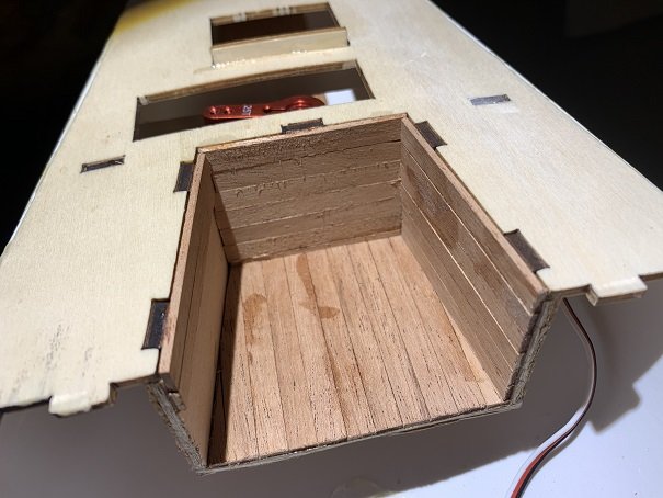
Greetings!
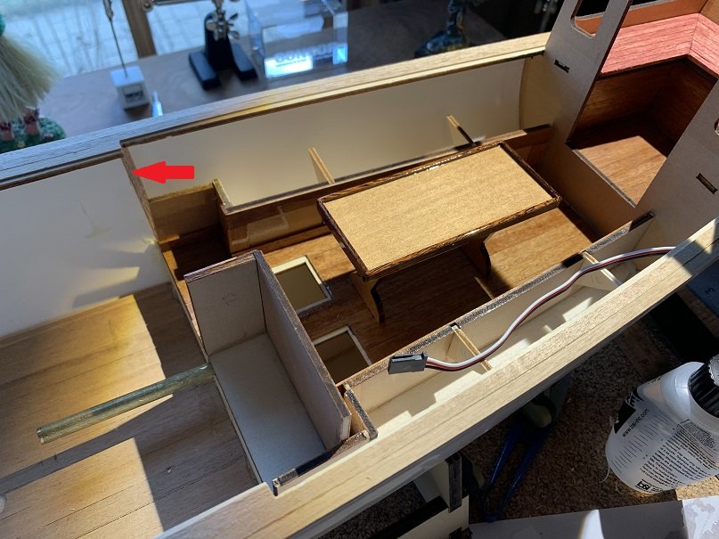
I varnished the cabin interior, including the table top which I hadn't glued on yet, and then I glued the table top in place. Then I glued the cabin sole/cabin assembly in place using epoxy on the plywood frames and Devcon plastic weld epoxy where it met the hull. Note the wooden braces that I compressed in place to hold the sole down (red arrow), I used one of these on the port side and one on the starboard, and the rear cabin wall held the sole down tight at the aft end.
- mtaylor, GrandpaPhil and schooner
-
3
-
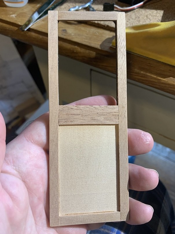
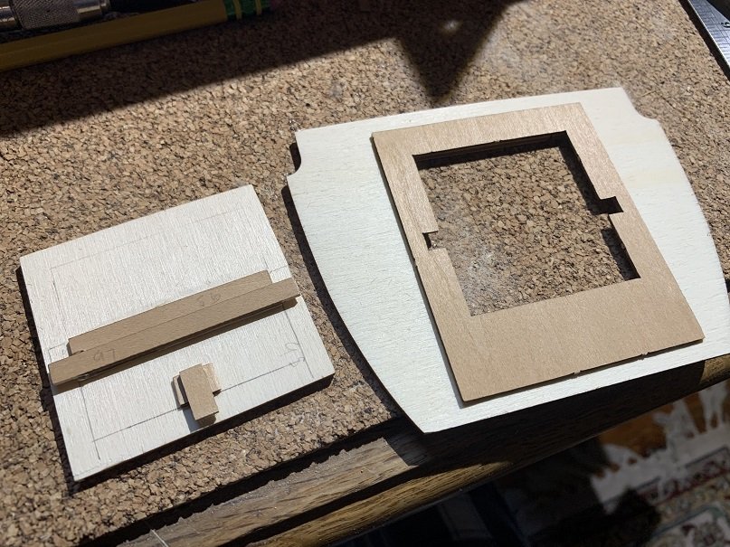
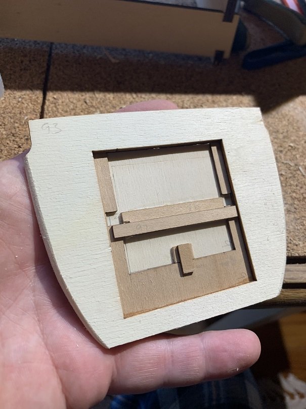
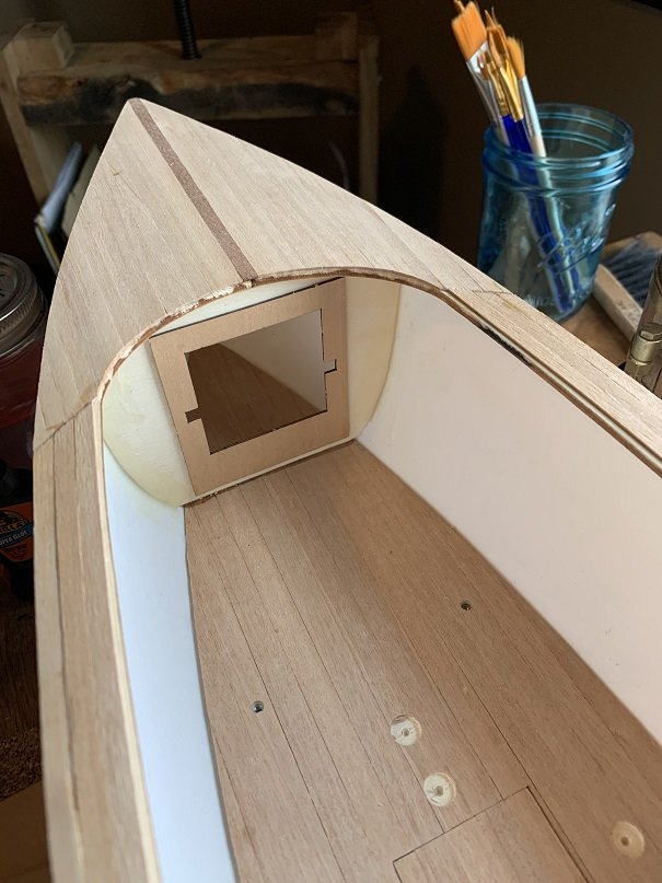
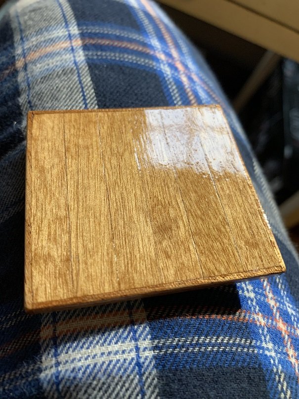
This is the forward bulkhead showing the hatch retention mechanism. Also a photo of the hatch installed into the bulkhead. I trimmed the hatch edges with hardwood and planked the face. I carved the bulkhead to match the hull curvature and then glued it in place with superglue to the sole and with Devcon plastic weld epoxy to the hull sides.
- GrandpaPhil, schooner and mtaylor
-
3
-
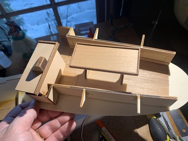
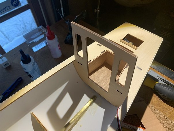
Time to get to work on the cabin! It is encouraging to see the model extend above the deck. I carved the aft cabin wall to fit the hull and then epoxied it in place; then got to work building out the interior of the cabin. The cabin interior was assembled to the point you see here. I think it is easier to do this assembly outside the model. I added additional trim throughout the cabin interior to break up large plain plywood areas and to cover exposed plywood edges.
- schooner, mtaylor and GrandpaPhil
-
3
-
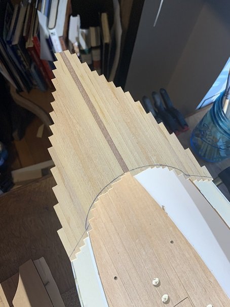
Hello! Time for some deck planking. I used 10sec superglue to glue down the deck planking. The plans do not call for planking in the cockpit, but I planked this area with mahogany.
- GrandpaPhil, mtaylor and schooner
-
3
-
At this point, I roughed up the OD of the propeller shaft tube, filled the end with wax to keep epoxy out, and epoxied it in place to all the frames and to the upper and lower keel pieces, and used devcon plastic weld epoxy where it exits the plastic hull.
- GrandpaPhil and mtaylor
-
2
-
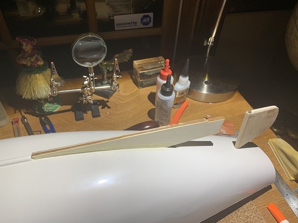
Next I built up the laminated keel, and dry fit it into position making sure it fit properly with the propeller shaft tube. At this point I had not glued the rudder shaft tube in place yet. It was important to have the rudder installed to make sure the keel is perfectly aligned straight with the rudder. With everything looking good, I glued the keel to the hull weith Devcon plastic weld epoxy, including a "fillet" of epoxy on either side of the keel where it meets the hull.
- mtaylor, schooner and GrandpaPhil
-
3
-
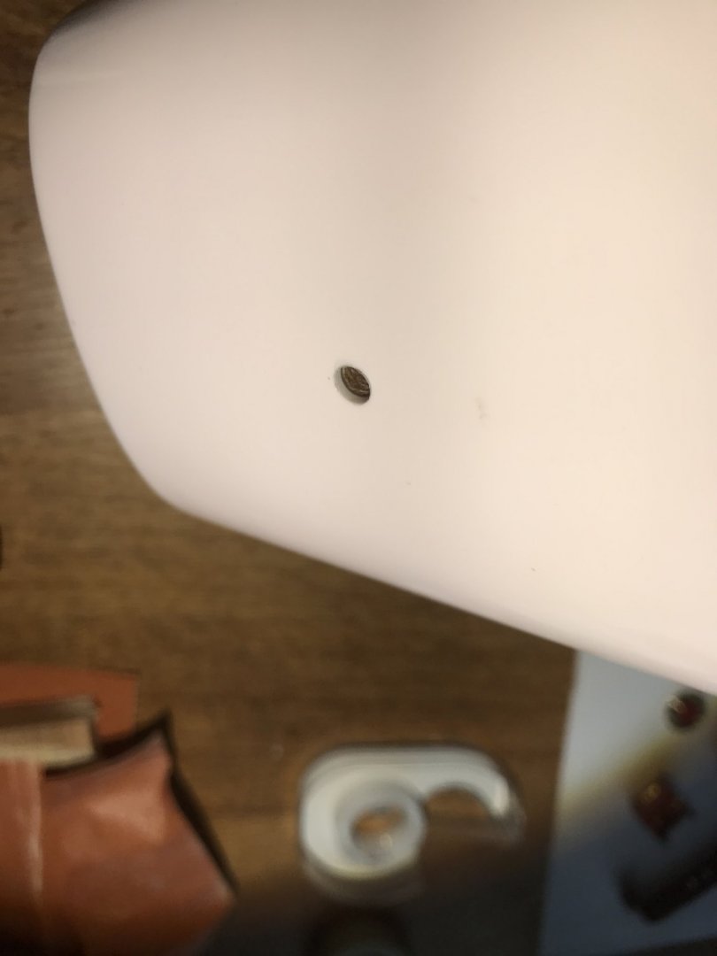
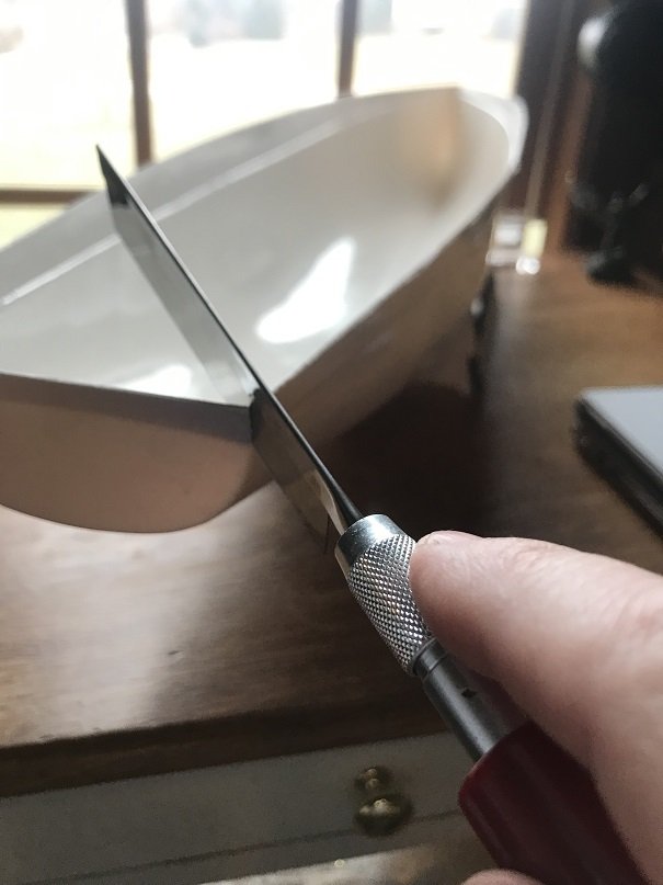
Drilling holes in boat hulls is always a big deal, especially below the waterline. At this point, is was time to cut the opening for the propeller shaft tube throught the hull. I laid the propeller shaft tube in place and then drew out where it would exit the hull. The resulting shape is an oblong hole. I drilled a hole at each end of the oblong hole and used a razor to remove the remaining hull material.

- mtaylor and GrandpaPhil
-
2
-
Good Morning! I am still just cranking out these posts of the work I completed through the year, and my goal is to ge caught up this morning to the current state of the project.
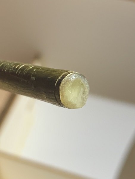
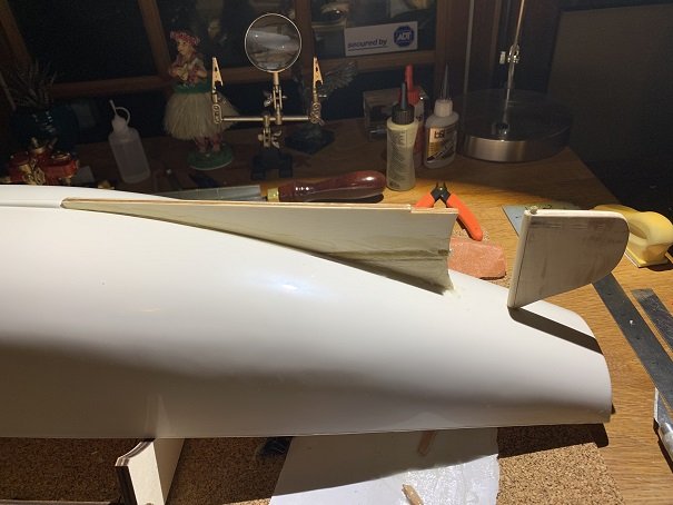
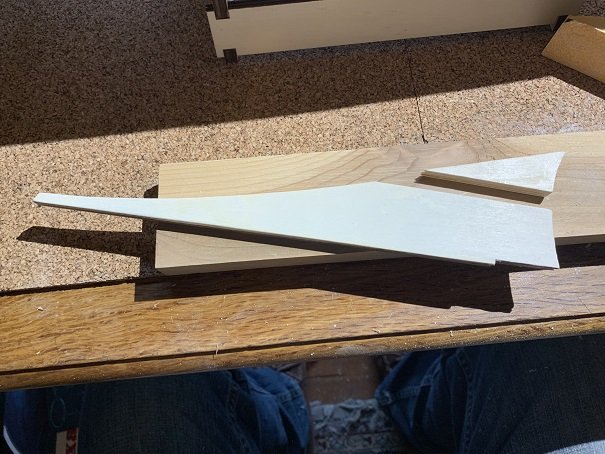
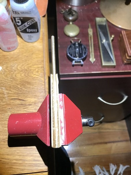
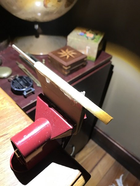
Next I built the rudder. It is laminated from plywood pieces and epoxied to the brass rudder shaft. There is a small reinforcing pin that in inserted perpendicularly through the rudder shaft and into the rudder also. When I was done with the rudder, I wanted a more hydrodynamic leading edge that what the design called for, so I added a half-round section of hardwood dowel to the leading edge.

- GrandpaPhil and mtaylor
-
2
-
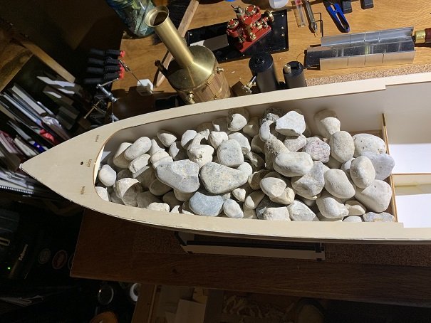
So with that all done, I glued the sole plate in place using Devcon plastic welder two part epoxy. I used a bunch or rock to weight the sole plate down. Again, that adhesive cures fast so work fast with it!
- mtaylor, GrandpaPhil and schooner
-
3
-
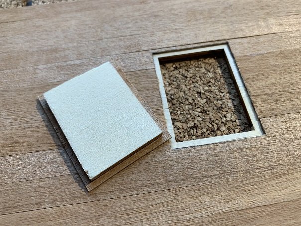
Here is the little hatch in the forward section of the sole plate. This hatch will allow access to the hull, in order to add ballast later.
- mtaylor and GrandpaPhil
-
2
-
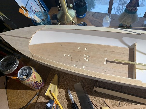
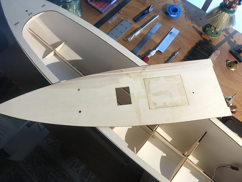
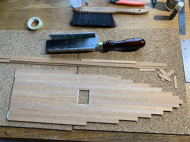
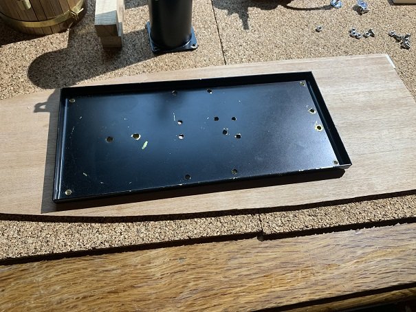
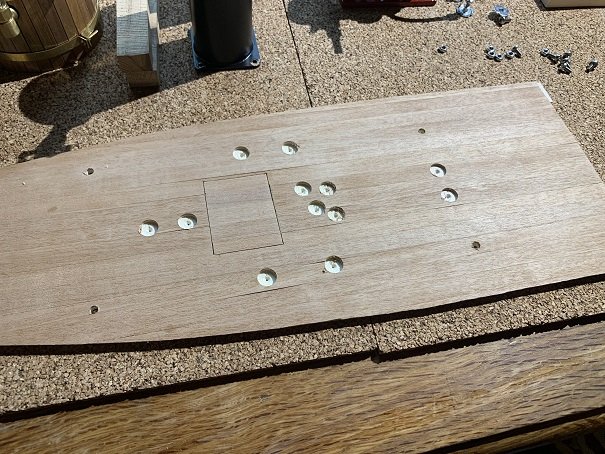
I figured it would be easier to prep and plank the sole outside of the boat, so that's what I did. The port and starboard edges of the sole need to be carved to match the curvature of the hull. This was also the time that is was very helpful to have the steam-plant built, so that I would know how to build this section of the boat where the steam plant will be installed. The flat tray assembly of my steam-plant is different than the steam engine design assumed by Krick in is design. So I epoxied in a filler piece to create a complete flat sole plate, and then I planked over the whole thing, while it was still outside the boat. I then located and drilled the mounting holes and epoxied the drive nuts to the underside of the sole; these will be used to bolt down the steam plant assembly. There are screw heads protruding down from the bottom of the steam plant mounting tray, so I used a forstner bit to counter sink holes into the sole plate to accomodate those protruding screw heads. At this time I also fashioned a tapered shim to both raise the engine so that the output shaft of the engine with be right at the centerline of the propeller shaft, and align it parallel with the angle of the propeller drive shaft.
- mtaylor and GrandpaPhil
-
2
-
Ahoy! With the sub-sole framework all epoxied and assembled, I glued it into the hull using Devcon plastic weld two part epoxy.
- GrandpaPhil and mtaylor
-
2
-
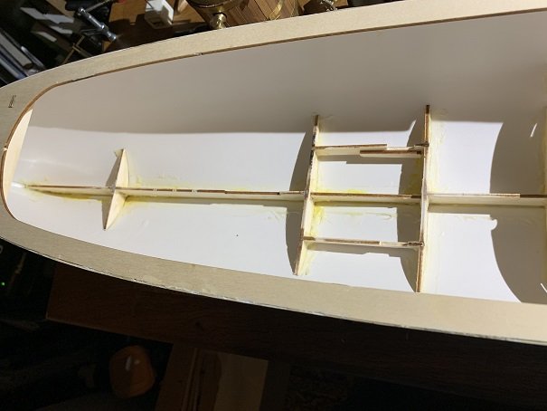
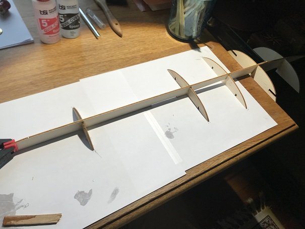
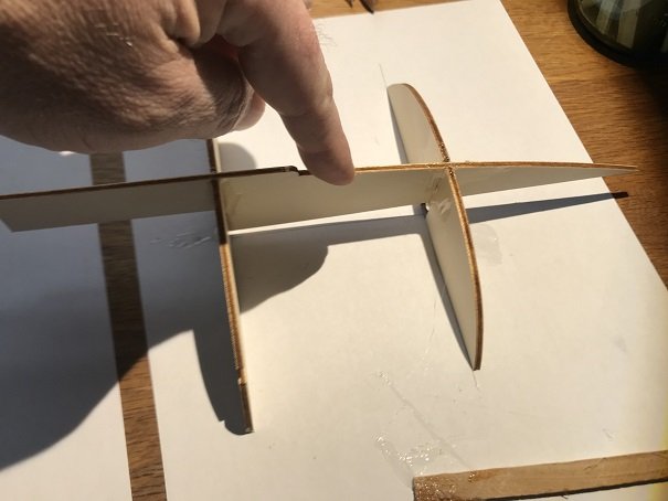
At this point I built the keelson and little frames/bulkheads that support the sole and cabin of the boat. These parts were all epoxied together.
- mtaylor, Ryland Craze and GrandpaPhil
-
3
-
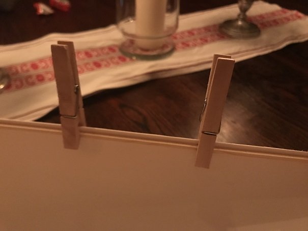
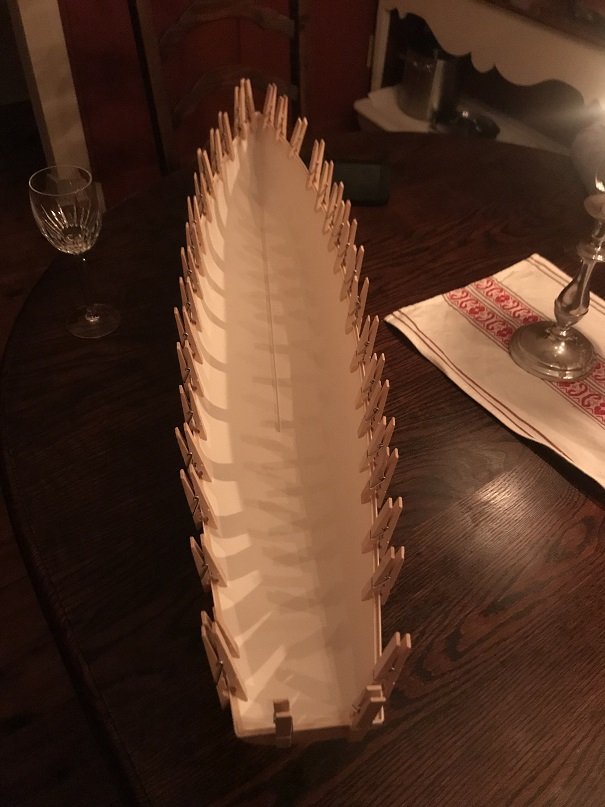
Then I glued the deck onto the cleats that I had glued in place earlier. I used Devcon plastic weld two part epoxy for this. I had tpo go very fast to get it down before the epoxy cured.

- GrandpaPhil, mtaylor and Ryland Craze
-
3
-
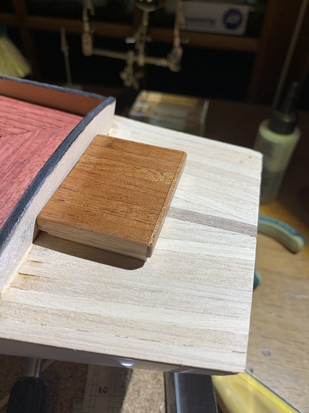
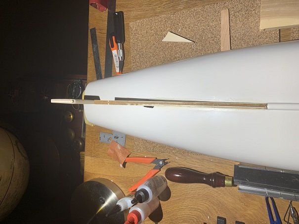
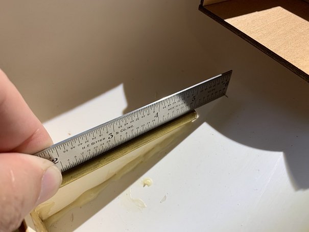
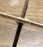
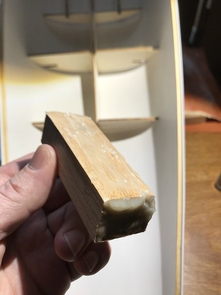
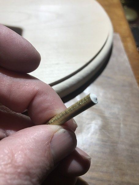
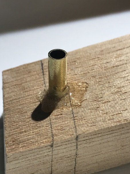
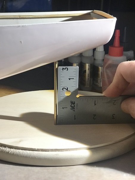
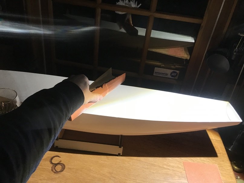
Before installing the deck, I installed the rudder support block. The plans call for smal gussets to be glued in place around the brass rudder shaft support tube. I think those gussets would be a mess to try to install. I made a solid mahogany block carefully fit into this location, and drilled a hole into it at the correct angle for the rudder shaft support tube. I glued this block to the hull with Devcon plastic weld two part epoxy. I drilled the hole slightly oversize to allow for final fine-tuning and truing-up of the rudder trunk tube in the hull. I filled the tube with some putty to keep epoxy out, roughed up the OD of the tube, gave it a thick coat of epoxy and inserted in into block and through the hull. I used a small square to ensure it was true in all directions (after making sure the hull was true in both directions also!) The brass rod that you see me holding the square up to, is the rudder shaft itself, which is protruding through the rudder-shaft tube that I am expoxying in place in the photo.


- Ryland Craze, mtaylor, schooner and 1 other
-
4
-
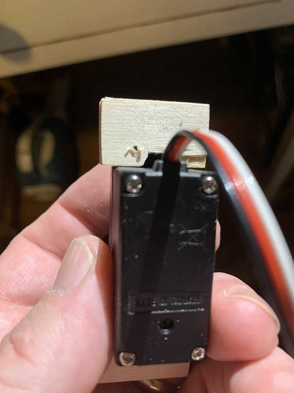
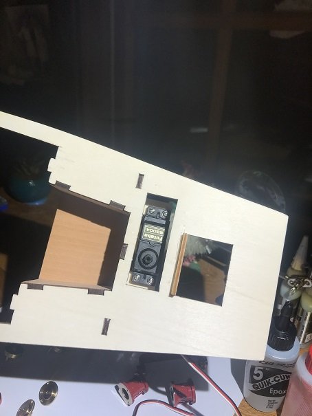
I will use Futaba servos and transmitters. I have never built a remote control model, so I am learning this as I go. I will use S3004 servos for both the rudder control and the engine controls. As I progress on this build, it has become evident that one must build support brackets and the surrounding model, to fit the remote control hardware. For example, the rudder control servo brackets that came in the kit were not sufficient to support the Futaba S3004 in my opinion. I built up thicker servo support brackets, such that the mounting screws are able to fully screw into a solid bracket. I also think it is important to be able to install and remove the servo from the ship model. In the Krick Alexandra, you will find that the rudder servo space is very limited. I carved a groove into the rudder servo support brackets to allow space for the servo and its wires , to be removed vertically out of the model.

- mtaylor, GrandpaPhil and Ryland Craze
-
3
-
With the first cleats glued in place around the inside perimeter of the top edge of the hull, I began assembling the deck and keel assemblies. The cockpit, along with a couple other parts, should be glued to the underside of the deck prior to glueing the deck down to the cleat that has been glued to the hull.

- mtaylor, GrandpaPhil and Ryland Craze
-
3
-
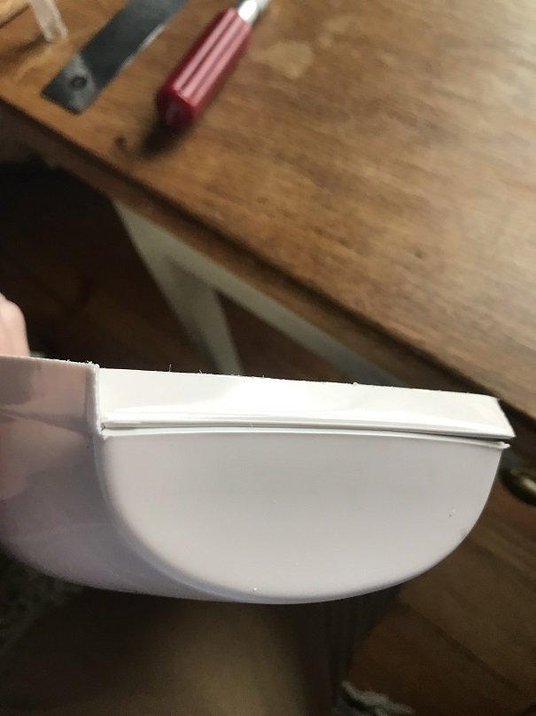
Now on to the ship! The hull is plastic and all other components are hardwood and plywood. The hull needed some trimming, after which I began installing and assembling the framework, deck, and sole. Note that anywhere I needed to glue a component to the plastic, I roughed up the plastic to provide a key to the adhesive.
- mtaylor, gjdale, GrandpaPhil and 6 others
-
9

Alexandra by Jason Builder - Krick - RADIO - live steam
in - Kit build logs for subjects built from 1901 - Present Day
Posted
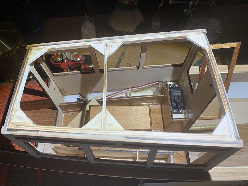
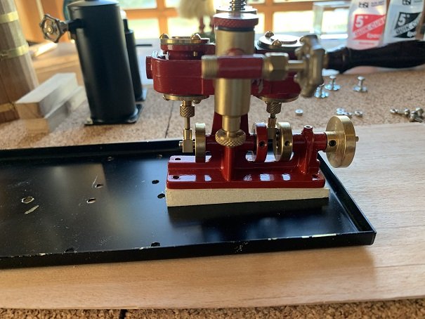
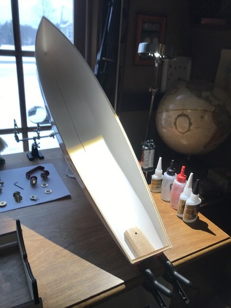
Hi Everyone,
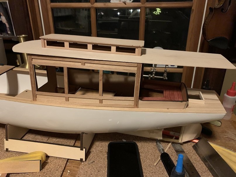
I set some pieces , including the steam-plant, in place to get an idea of how she’ll look. I’m happy with how snug the roof frame sets into the cabin sides.
Jason