G.L.
-
Posts
1,553 -
Joined
-
Last visited
Content Type
Profiles
Forums
Gallery
Events
Everything posted by G.L.
-
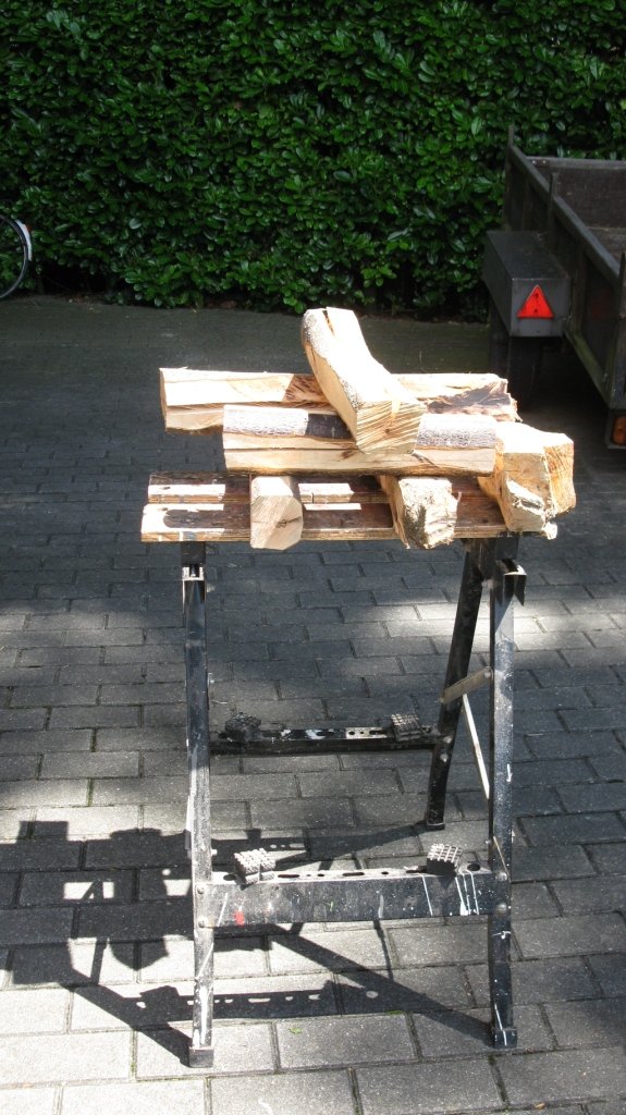
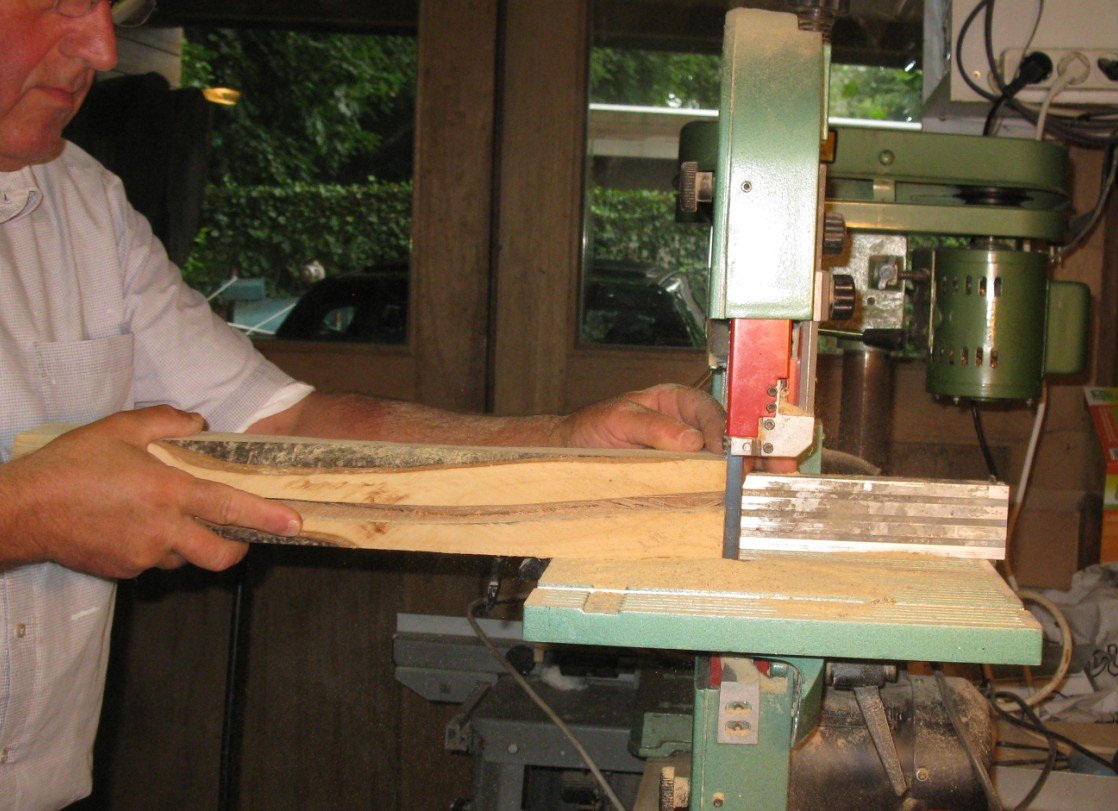
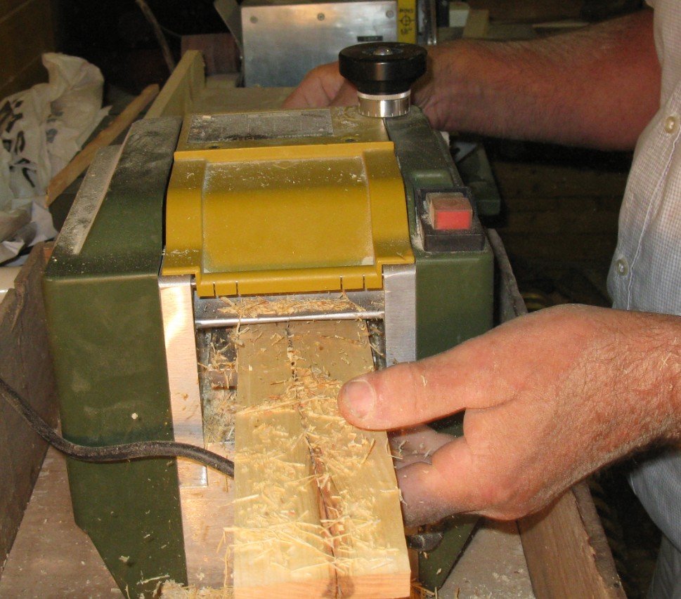
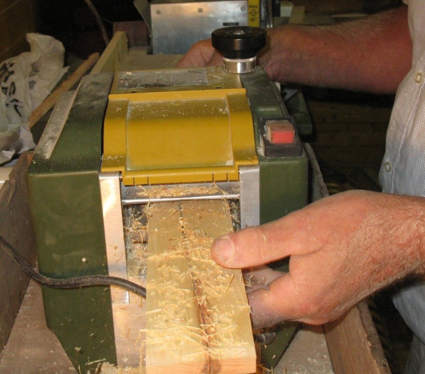
 Part 3: Making keel and stems 3.1 Time to get to work now. The wood that I use is provided by my garden. Many years ago I planted a cherry tree in the garden, when the tree started to bear fruit, it were plums instead of cherries. Two years ago I made finally the decision and removed the tree and replaced it by a real cherry tree. The wood is dry now and ready to be sawn and planed into planks. Remark afterwards: After completing stems, keel and frames I made some samples of the finishing color for the planking an discovered that the plum wood did not give a finishing result that I liked. Therefore for the planking of the hull I changed to oak, the wood which was in reality used to build the Flemish shrimpers.

-
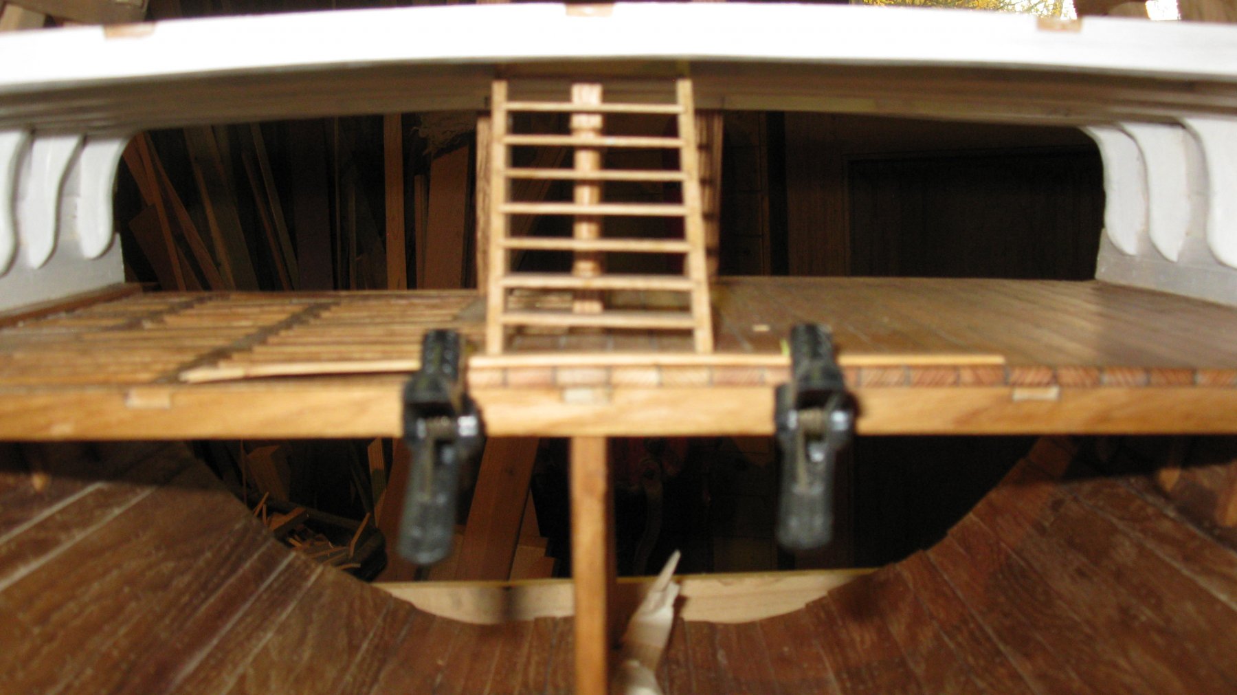
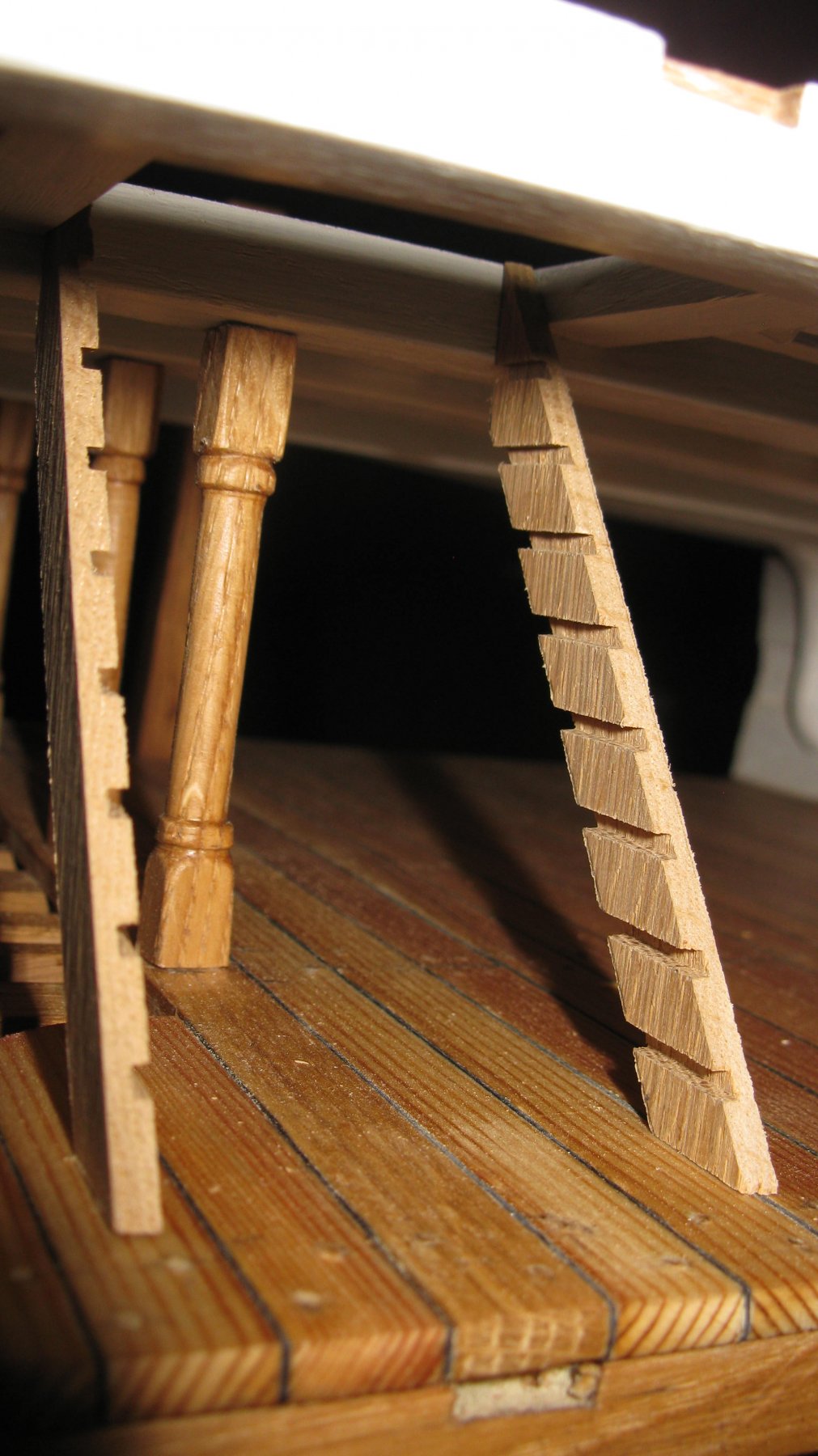
Ladder finally in position, darkened and varnished.
-
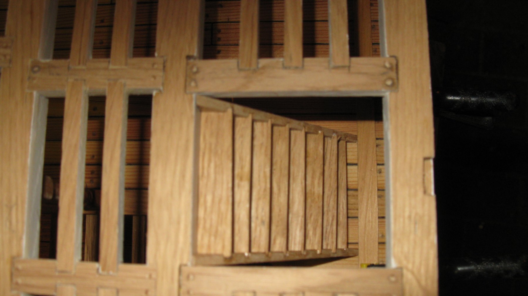
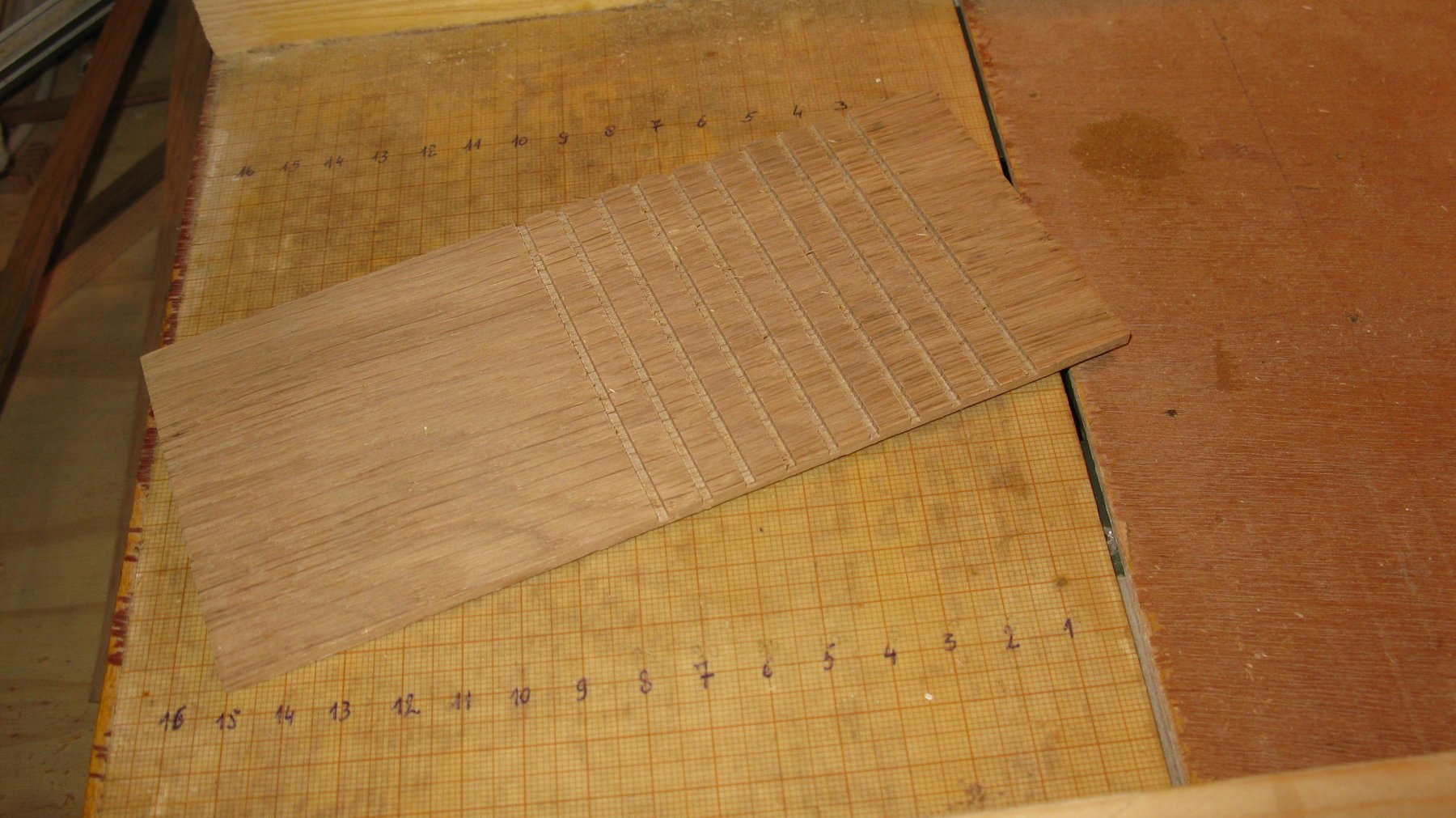
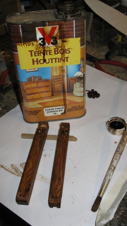
Before gluing the ladder in to its spot, I color it with dark stain. On the picture you see the bitts which I colored simultaneously.
-
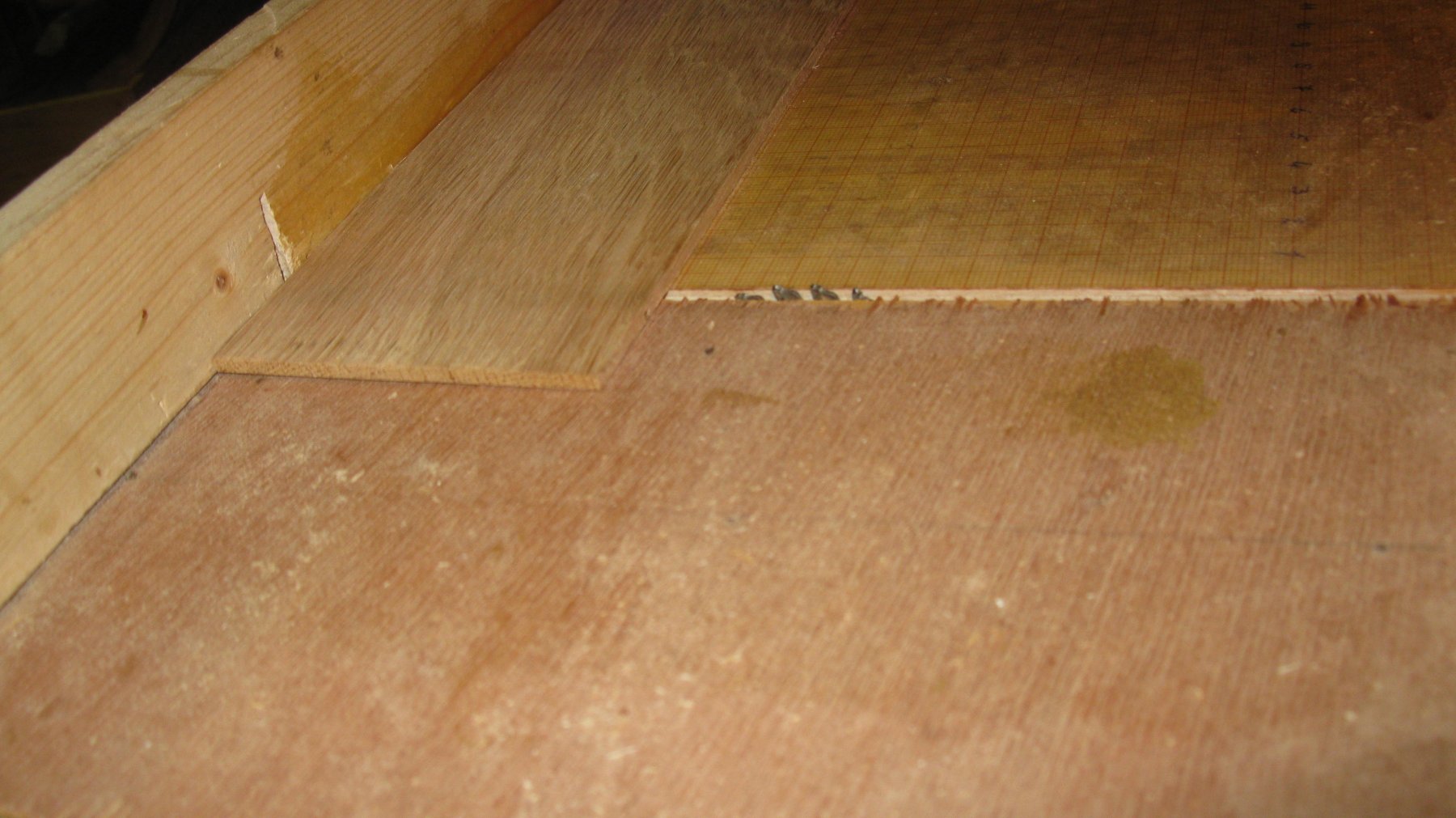
Before the glue is entirely dry, I place the ladder in to his position in the model (not yet gluing it fast), so the glue can harden further while the ladder has its final shape.


-
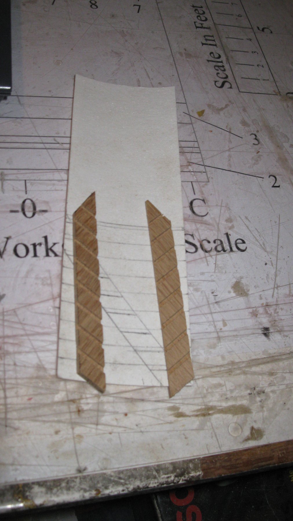
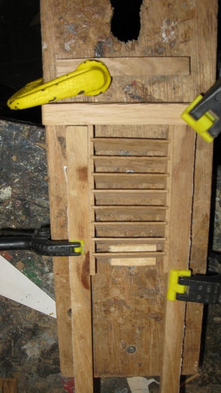
To glue them together, I use a very simple jig of some strips of wood held parallel with clamps on the correct intervals.
-
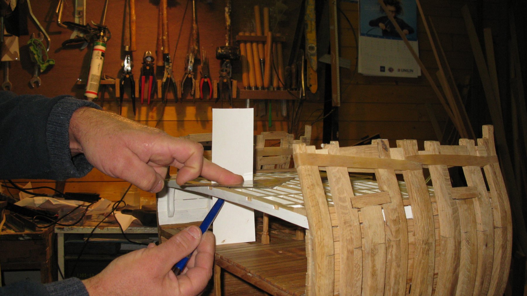
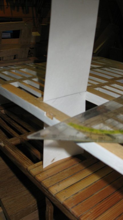
I check them out on the model.

-
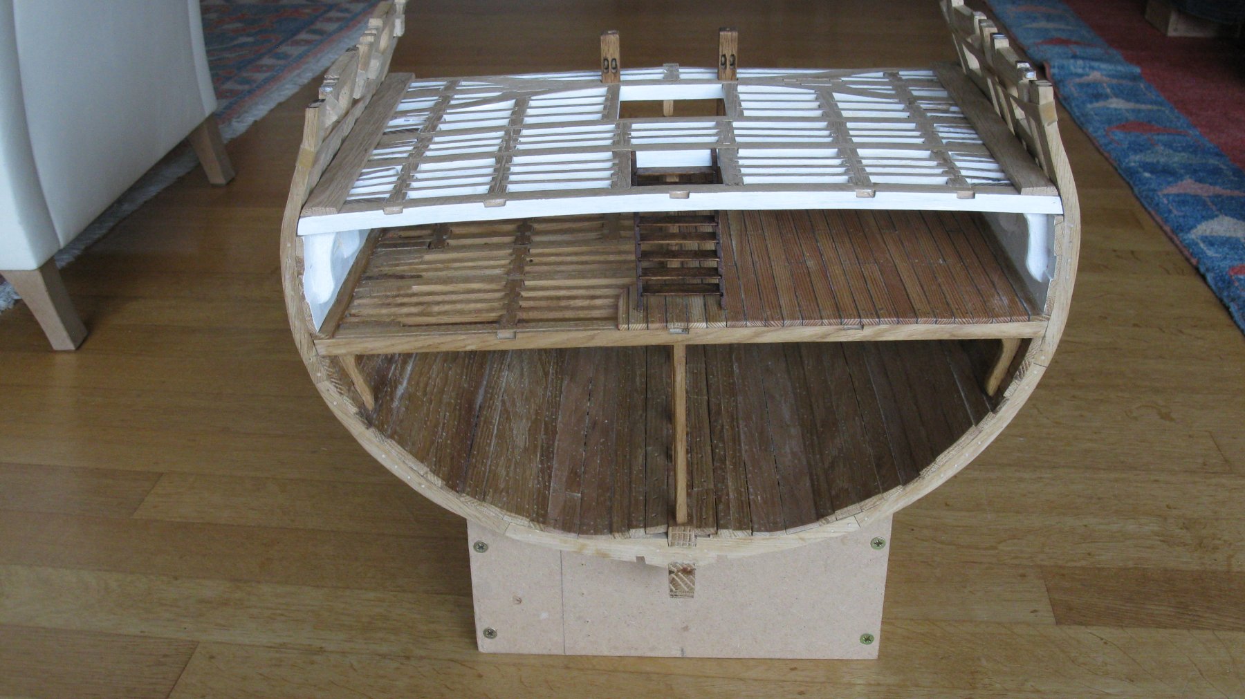
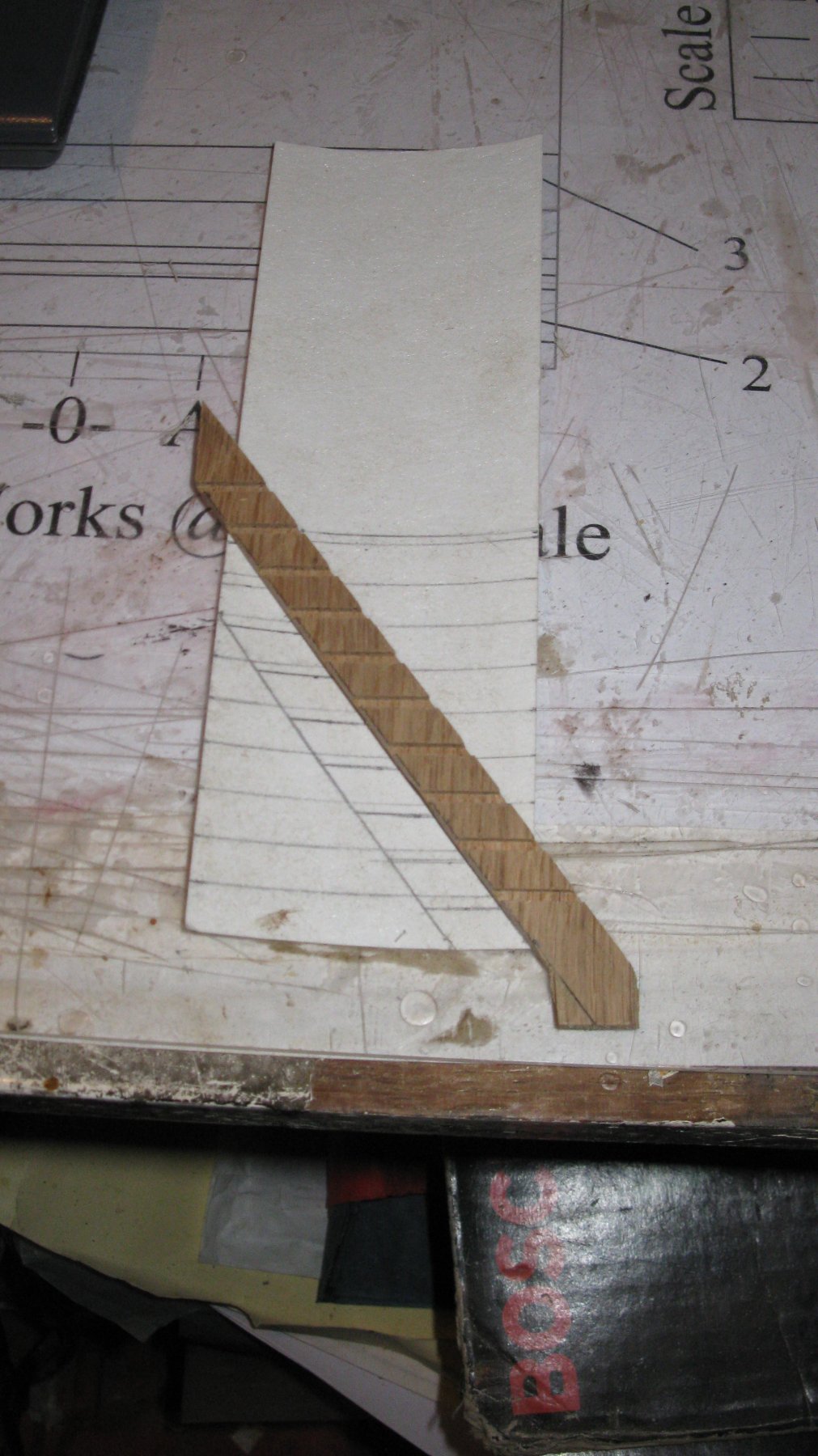
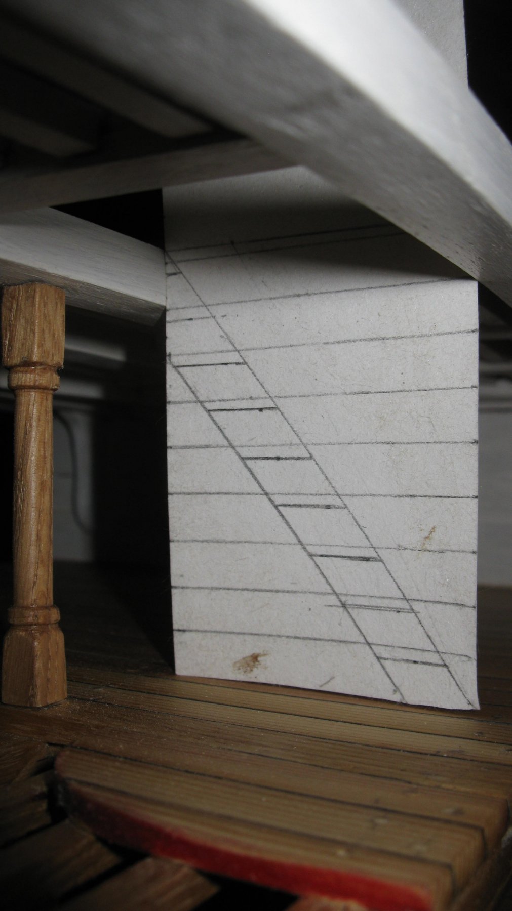
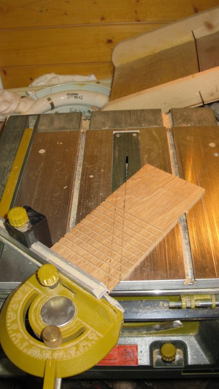
I saw the stringers out of the planks in the angle I determined before on the model.


-
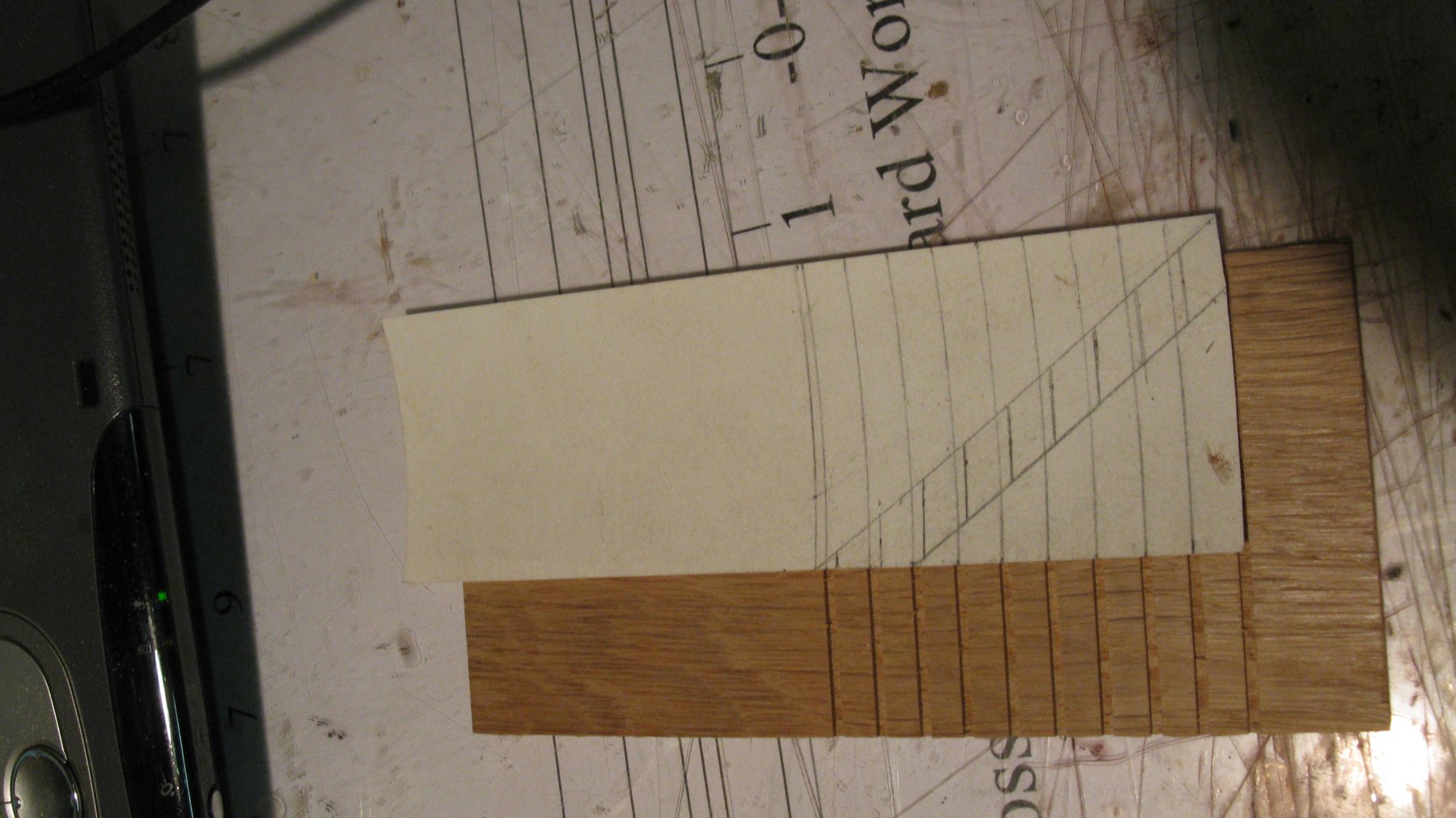
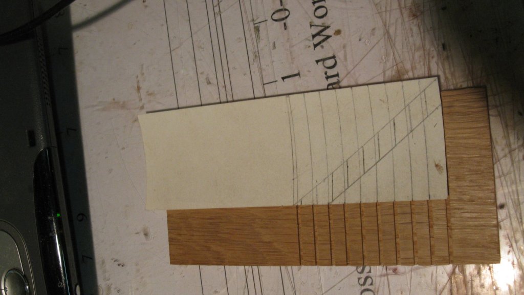
The stringers are 2.5 mm thick, so I plane two planks to that thickness (2 because there have to be made 2 stringers in mirror image). I set my table saw for a thickness of ±1.2 mm and saw the grooves for the steps. Some time ago I made a simple table saw sled on which I glued a piece of millimeter paper, that makes it easy to saw the groves exactly parallel and with the correct intervals.

-
I will now make the forward hatch ladder. Because there is always a slight difference between the plans and the execution of those plans, I take the dimensions of the ladder immediately from the model.


-
Glad You like it. Thank you , Dereck
-
Patrick, Looks great! If I was You I would also treenail below the waterline, just for completeness. Looks me a nice job for a Sunday afternoon in a comfortable and heated hobby room like yours with some good music at the background. G.L.
- 756 replies
-
- 3
-

-
- galleon
- golden hind
- (and 2 more)
-
2.15 Last winter (winter 2015-2016) I completed another two drawings of the assembly of the keel, stem, stern and frames.

-
2.14 The 4 cant frames are drawn in this way. Next things to draw are the keel, the stem and the stern.
-
2.13 The final copy looks like:
-
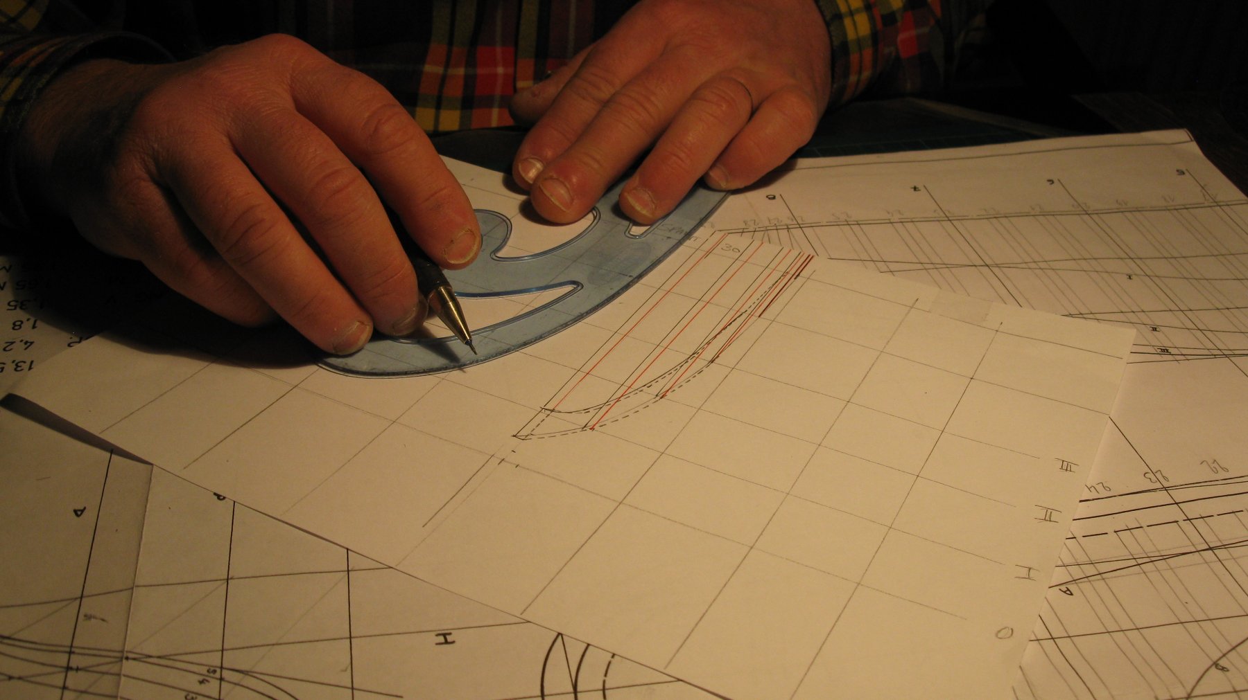
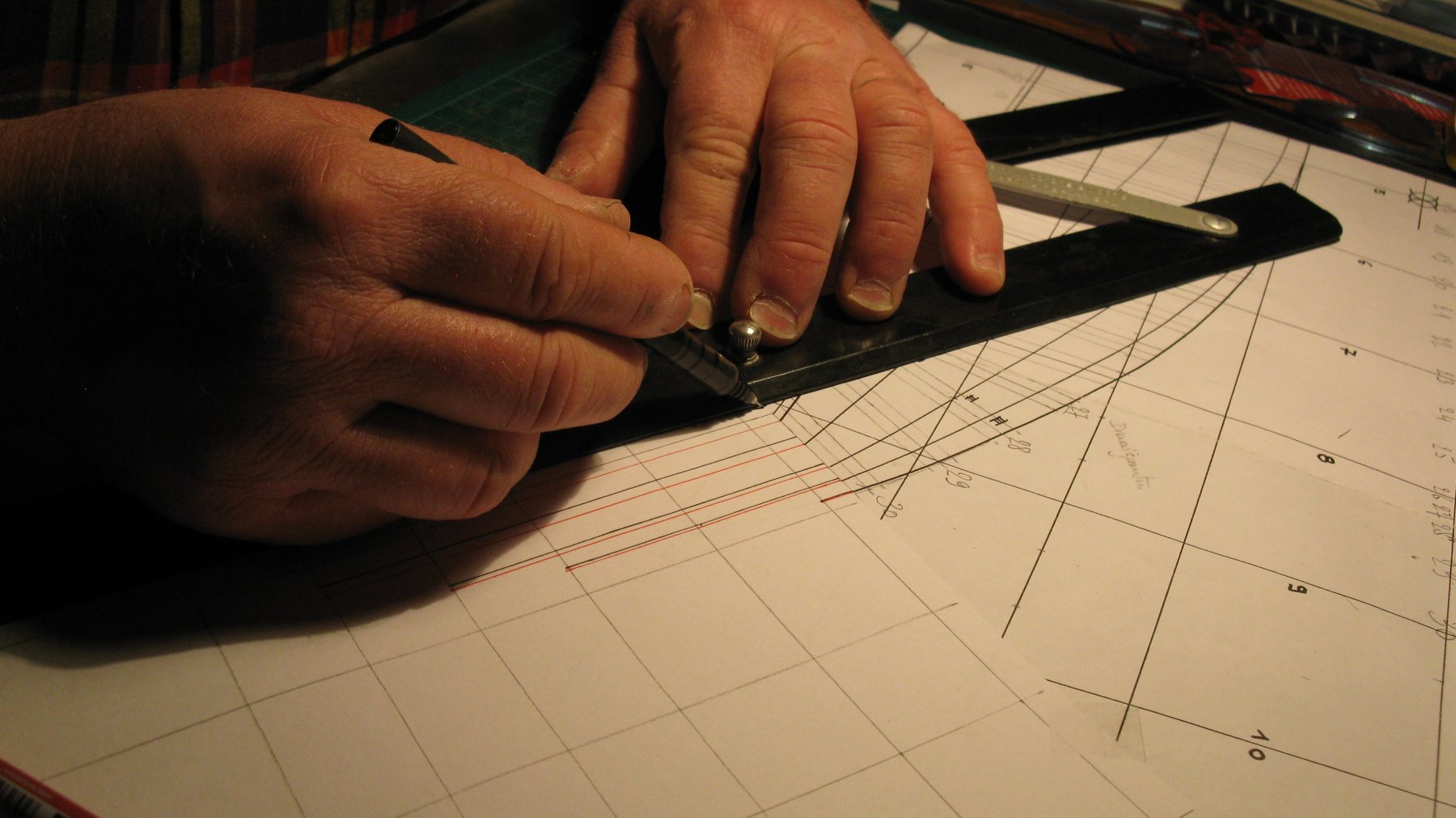
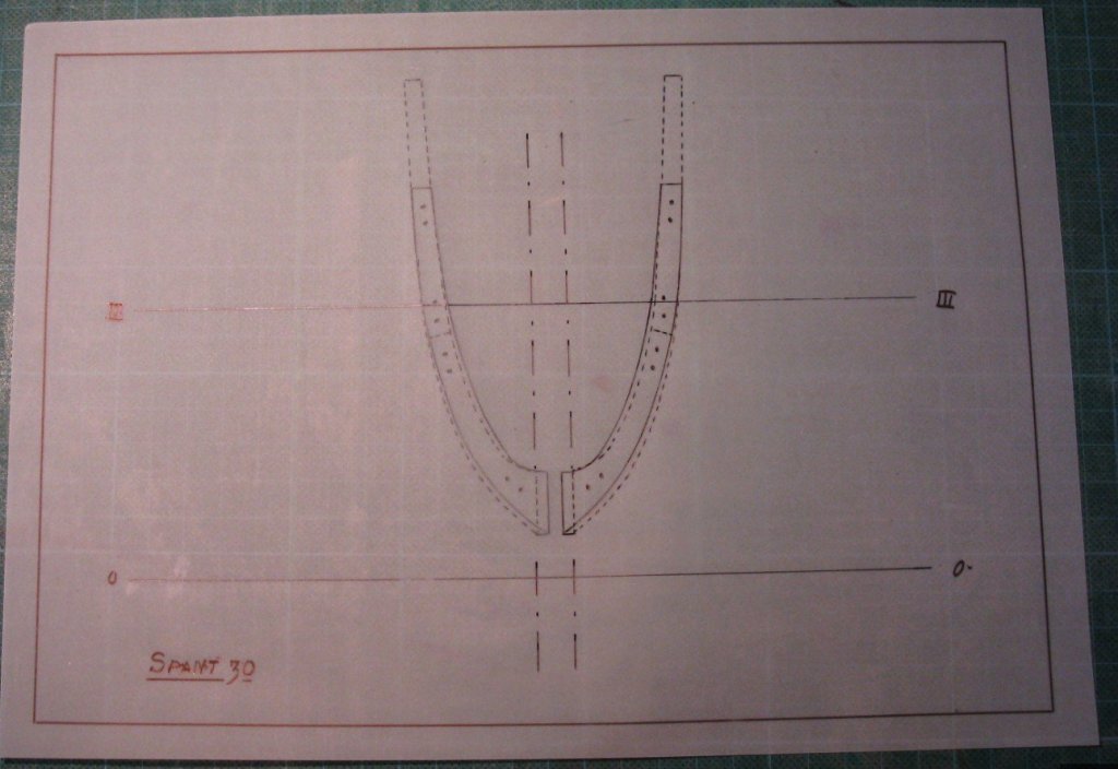
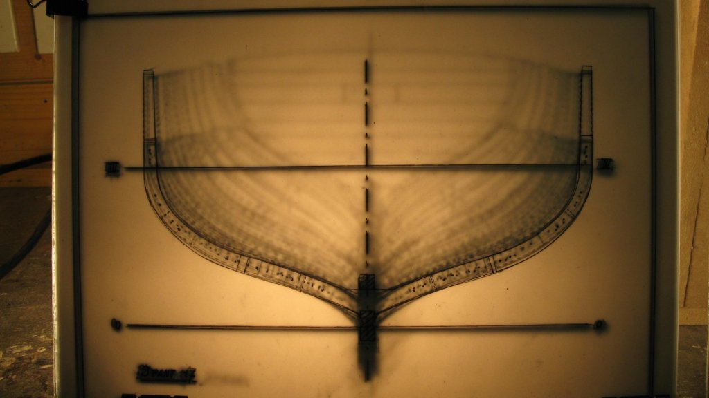
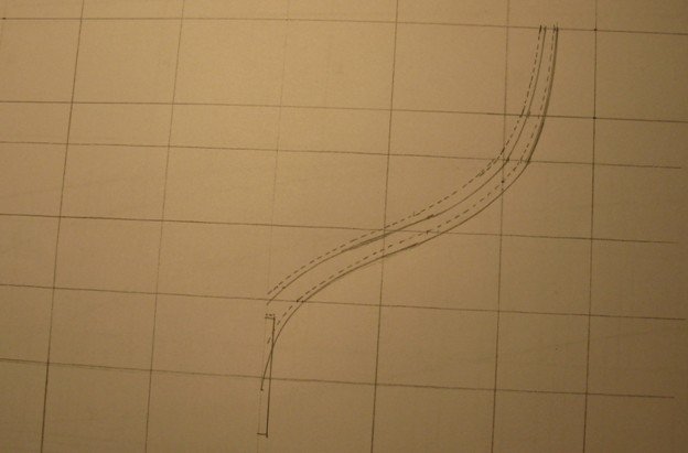
2.12 Once all transferred intersections on the grid are connected, the shape of the cant frame appears.
-
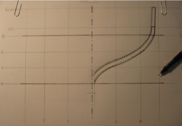
2.11 Afterwards I transfer the intersections of the frame with the different waterlines in parallel with the centerline of the grid to the waterlines on the grid. The black lines are the intersections of the back of the frame, the red lines the front.
-
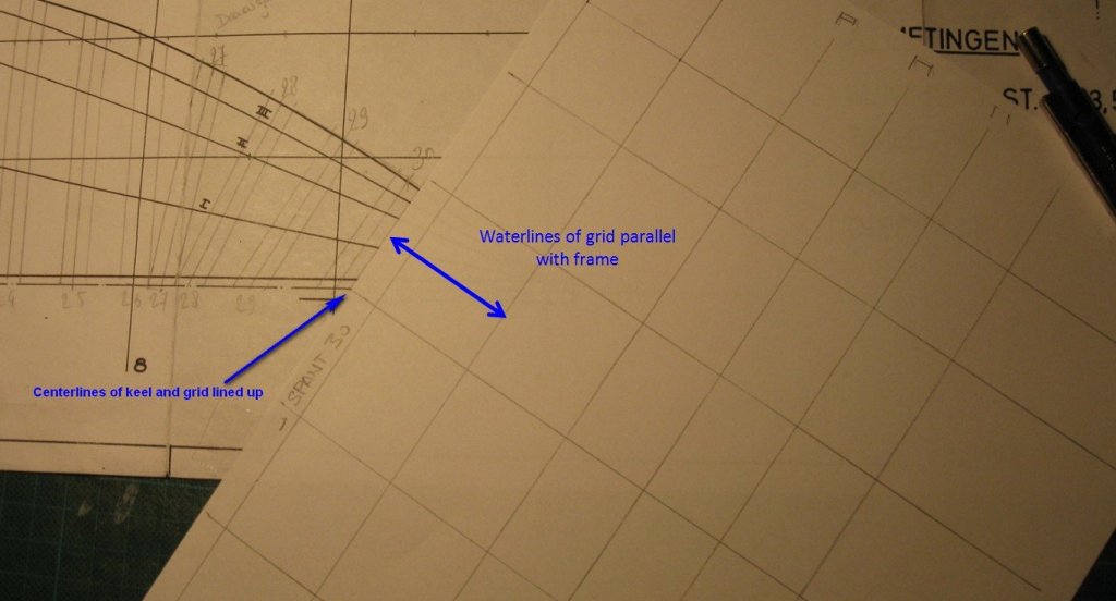
2.10 All the square frames are drawn. For the cant frames another technique is to be used. I place the grid with its centerline touching the centerline of the keel on the fore end of the frame and the waterlines on the grid in parallel with the cant frame.
-
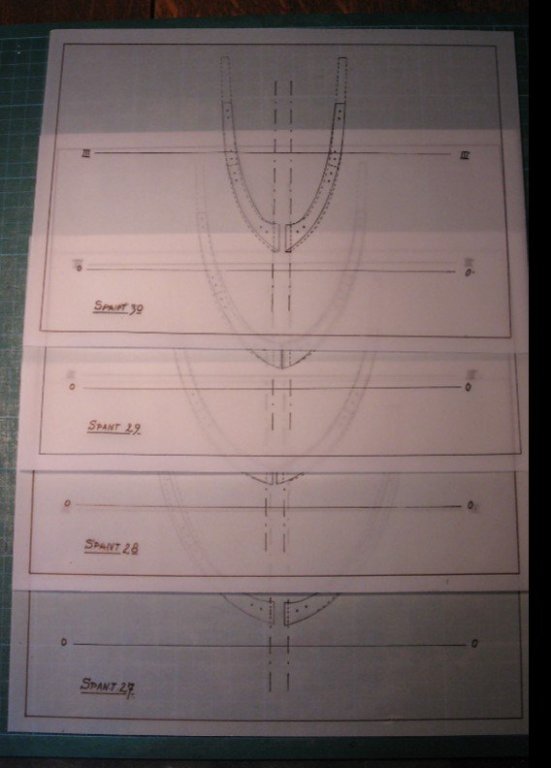
2.9 I didn't yet mention the dimensions of the Ostend shrimper: - LOA: ± 13 m - Beam: ± 4 m - Depth: ± 1.8 m - Draft: forward: ±1.3 m amidships: ±1.6 m aft: ±1.9 m

-
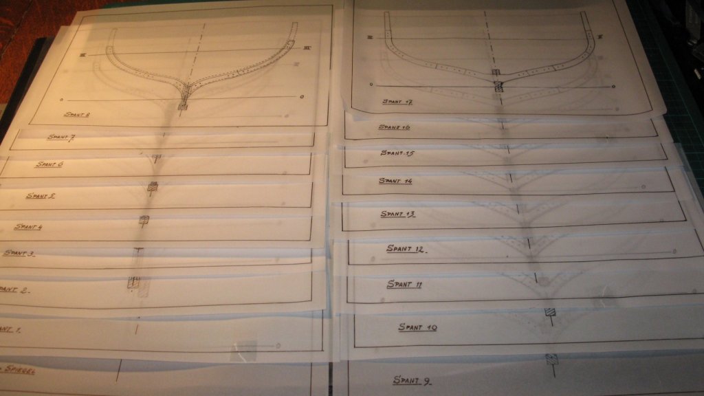
2.8 When I place all the tracing papers one after another between two plates of glass with a strong light behind it, I have already an impression of the interior of the hull.
-
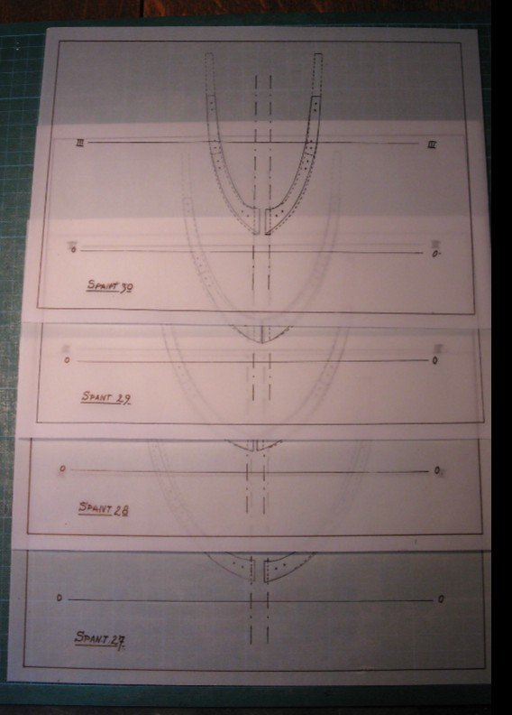
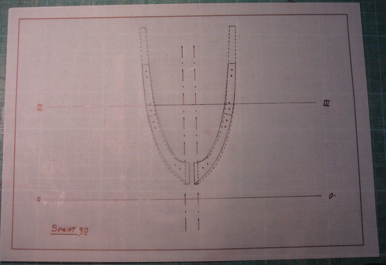
2.7 This has to be repeated for all 30 frames, so I know what to do in the weeks to follow. The back half of the frames is drawn. Now the forward part.
-
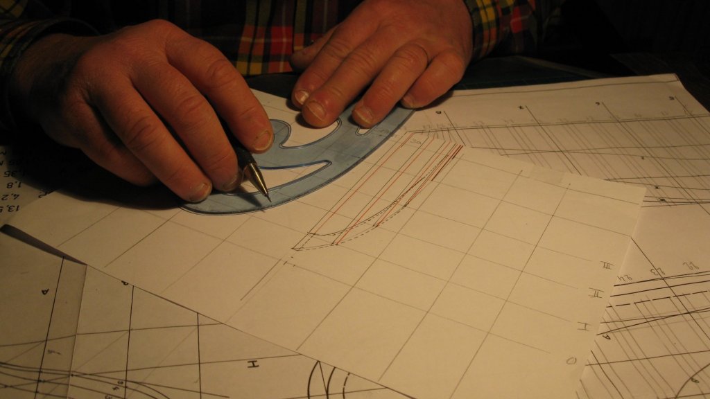
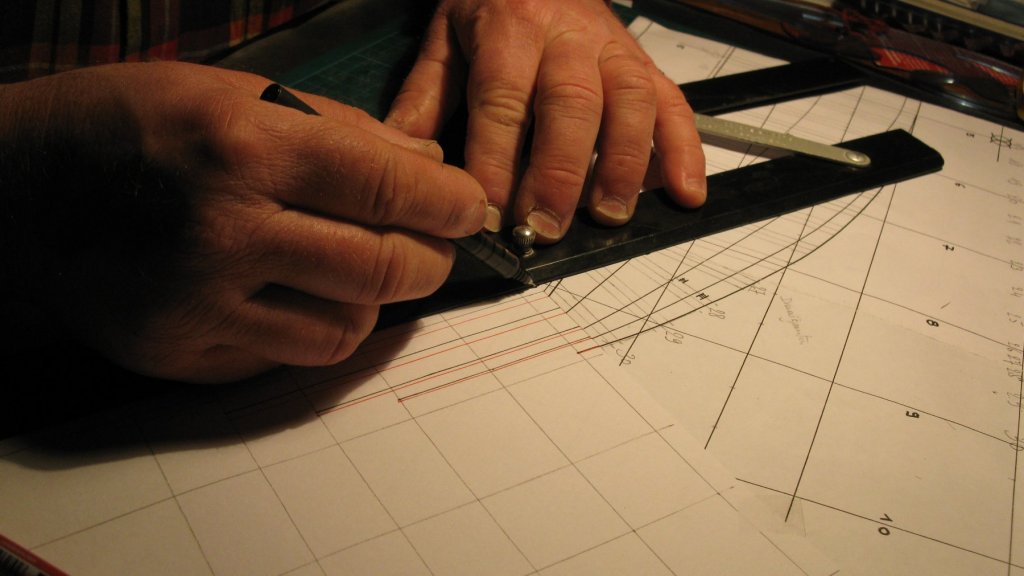
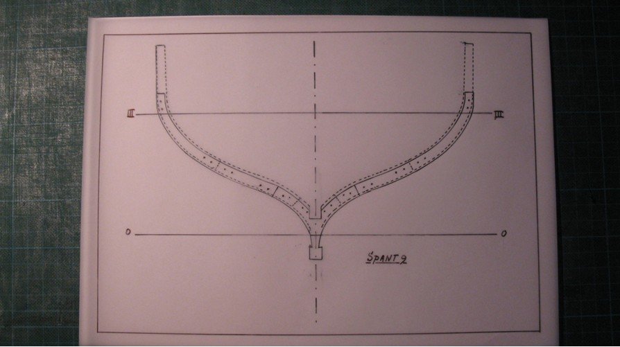
2.6 Then once again with the tracing paper reversed and I have a drawing of a complete frame.
-
2.5 To obtain a full frame. I copy the half frame on tracing paper.
-
Thanks, Patrick
-
2.4 When I repeat the same procedure with the aft end of each frame, I have also the shapes of the bevel of the frames (dotted line).
-
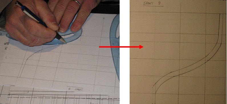
2.3 Connecting all those measurements with a smooth curved line gives me the shape of the frame.