


aydingocer
-
Posts
898 -
Joined
-
Last visited
Content Type
Profiles
Forums
Gallery
Events
Posts posted by aydingocer
-
-
-
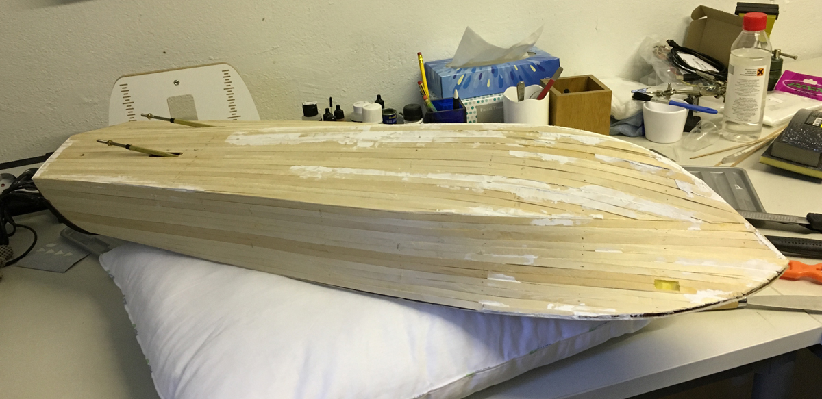
END of BUILD DAY 20.
6,5 hours today.
71 hours into build in total.I managed to do sanding and plank altogether 10 strips today. Not bad. Here is the status below. Thanks for watching.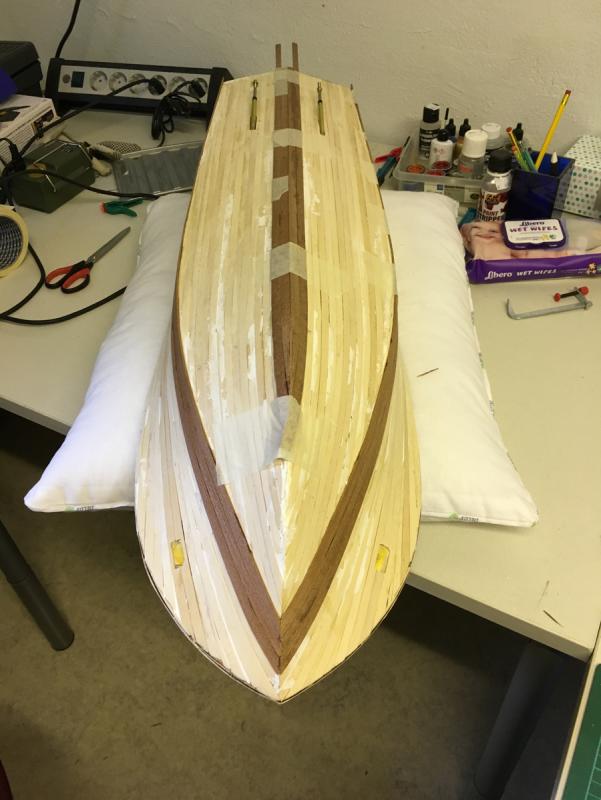
- gjdale, MarisStella.hr, mtaylor and 5 others
-
 8
8
-
-
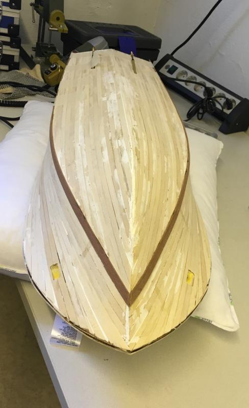
Let the 2nd planing begin!
Planking material: 1,5mm x 8mm mahogany (as opposed to 1,5mm x 7mm lime used in first planking). This is interesting as I would normally expect the 2nd planking strips to be thinner. These ones are as thick as the lime planks underneath.
2nd planking follows pretty much the same sequence as the first planking. Start with 1 strip from the center of the each side of the hull, then switch to the middle of the bottom, then continue in alternating turns.
-
BUILD DAY 20. 2nd PLANKING COMMENCES.
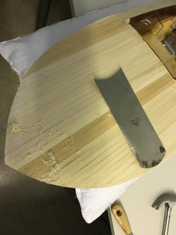
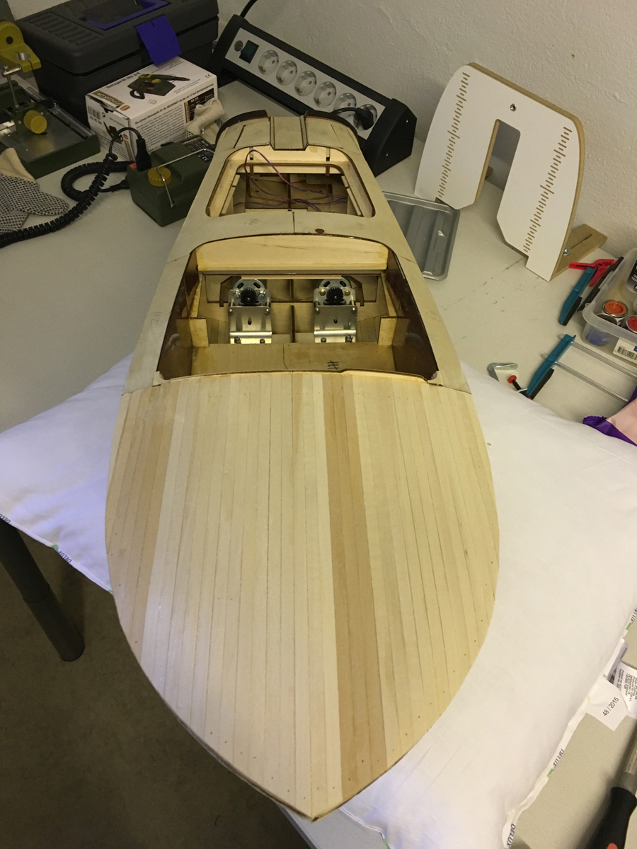
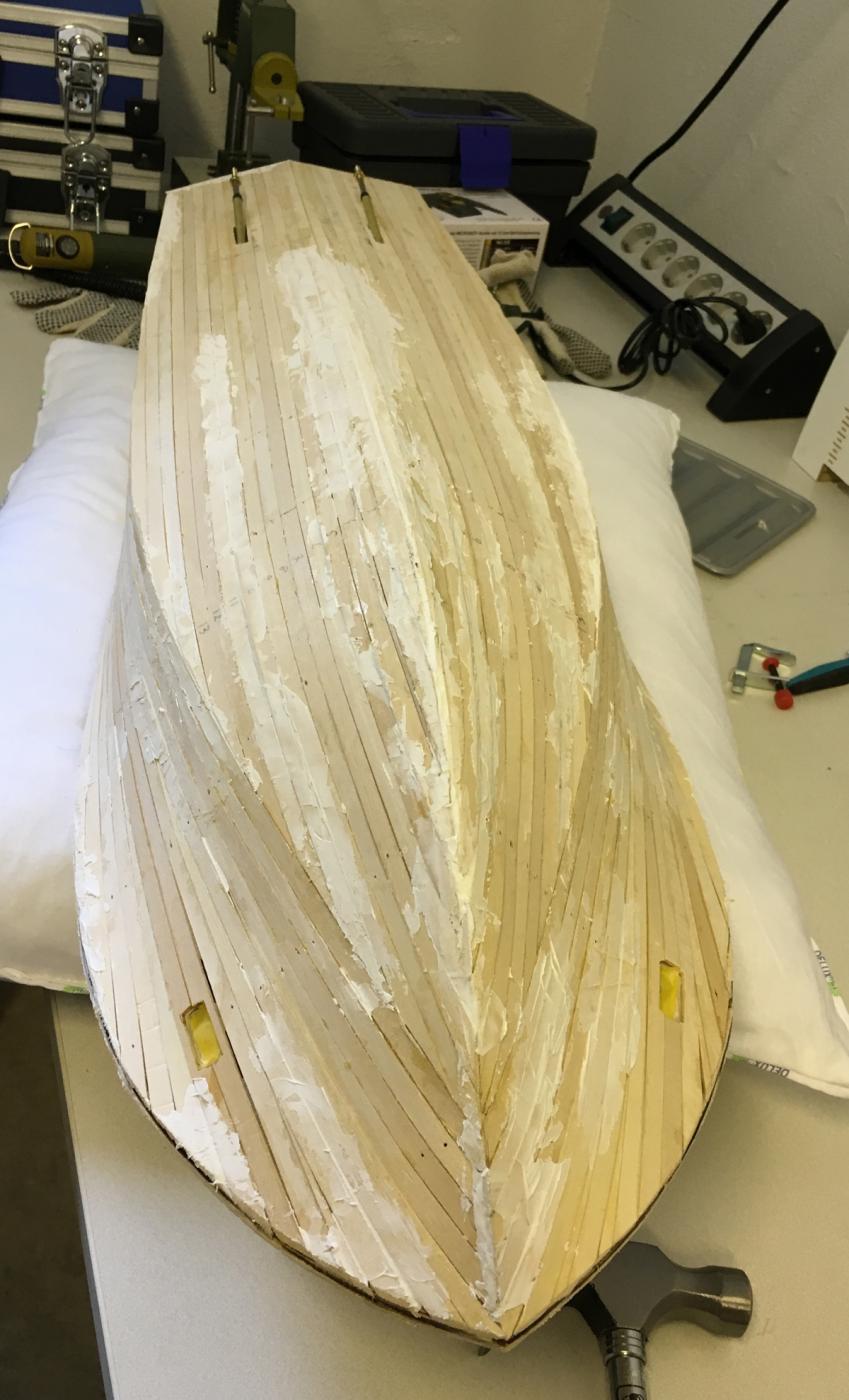
Today I spent some 1-2 hours for sanding, after which I concluded that the surface is smooth enough for 2nd planking. My tools were Proxxon orbital sander with 180 grit paper and a sanding drum, same grit paper, self-made sanding drum from a pool toy (water gun). The latter has been a perfect tool with its soft cushion especially on the curvy surfaces:
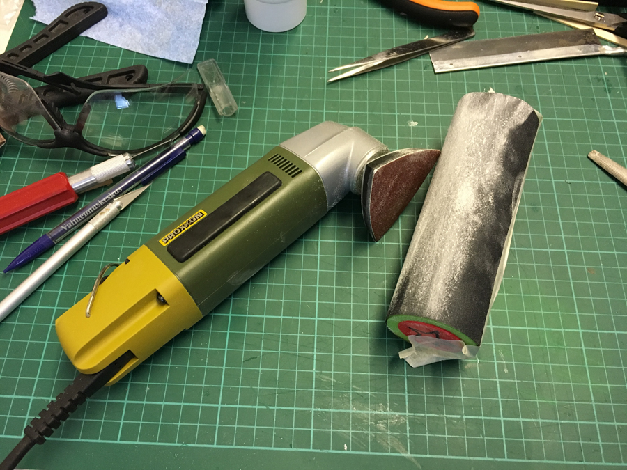
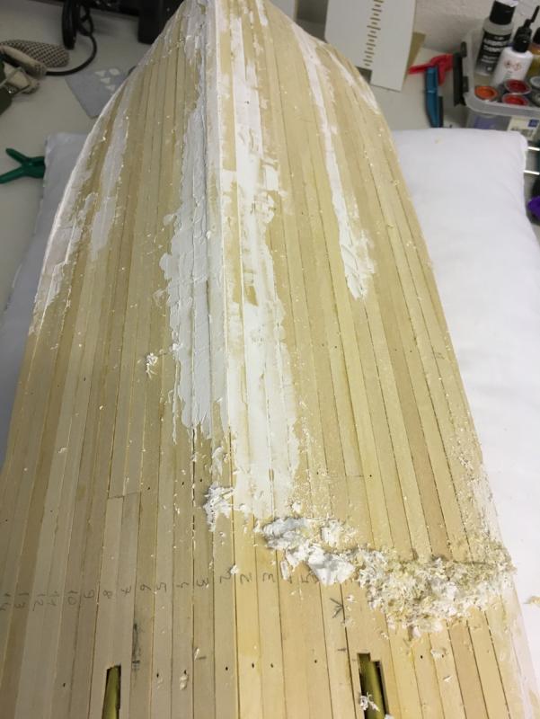
The hull is now ready for 2nd planking:
-
-
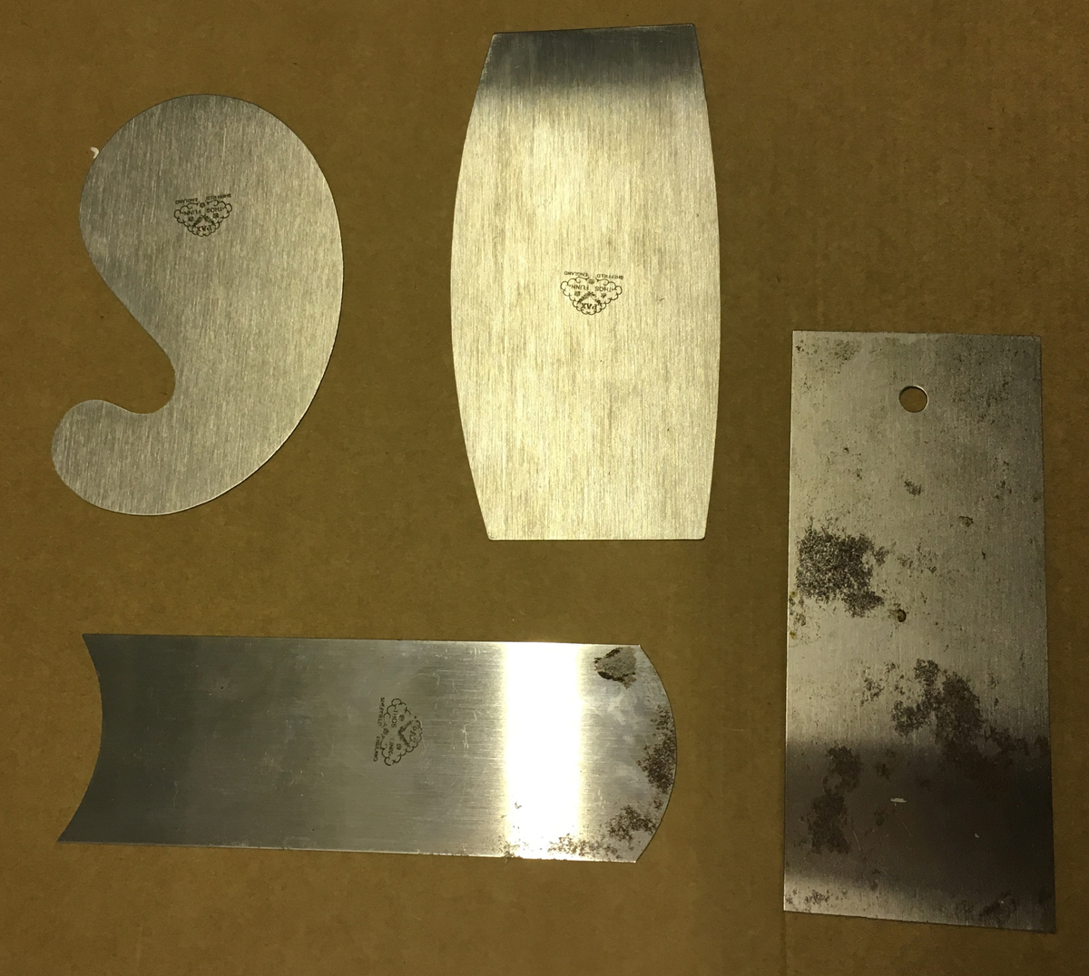
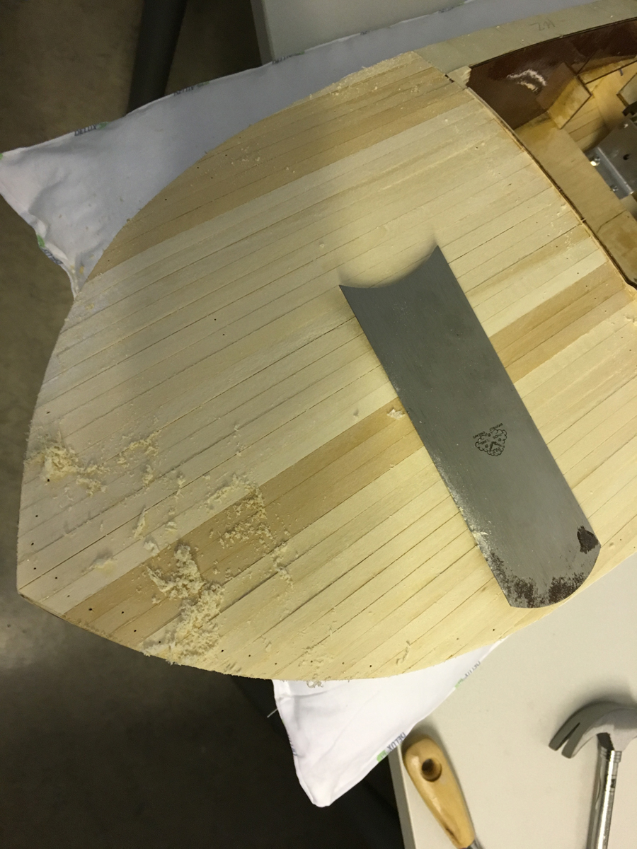
Back to work. Before sanding I decided to use some scraper in order to get rid of the glue residues and to level the stripes for helping the sanding process. I have this set of scrapers with different contours quite useful for this boat, which has rather curvy surface:
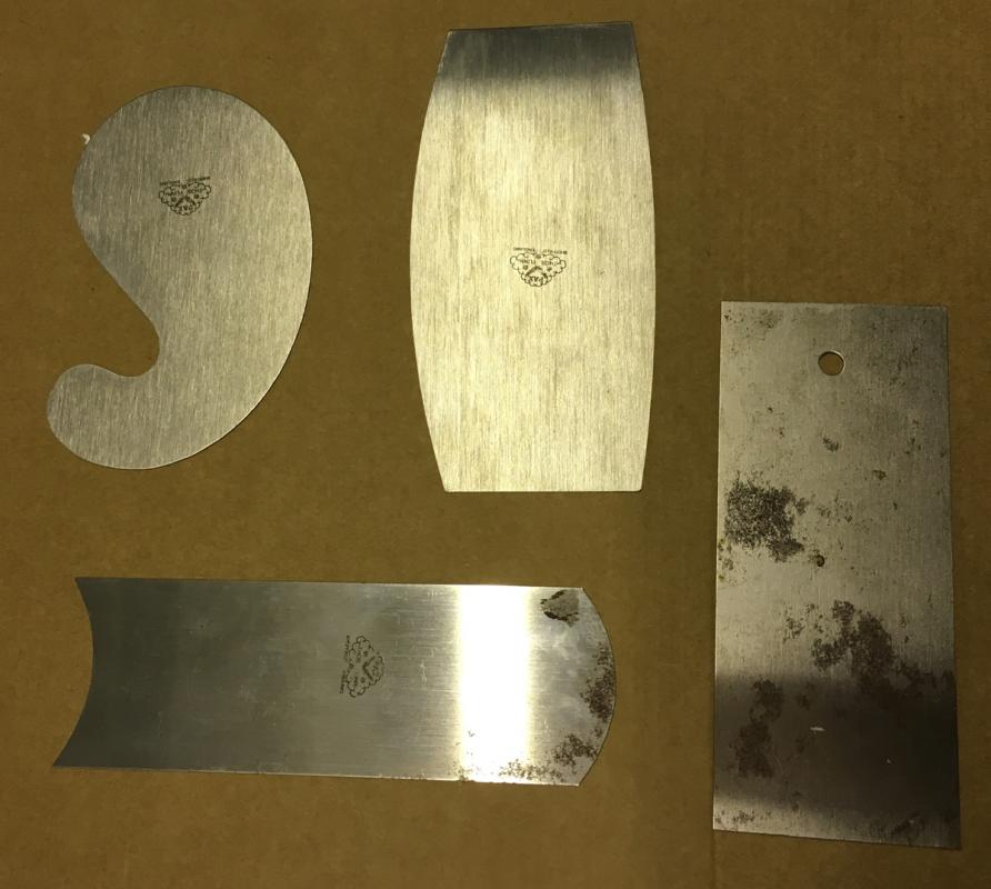
They work quite effectively indeed:
-
-
-
BUILD DAY 19. COMPLETING 1st PLANKING.
 No, I am not one of those who have been hypnotised by Pokemon Go, which became available in Finland as of yesterday!
 I have had roughly 4 hours today to finally complete 1st planking and start preparing the hull for the second planking.
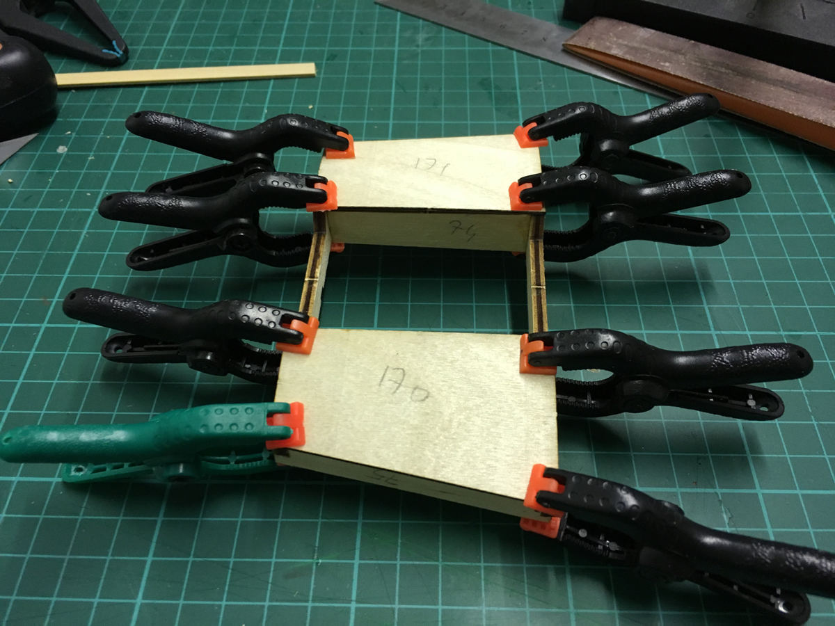
First, finishing the first planking of the removable engine cover (1st planking of this section is made by veneer sheets). After the planks are glued, the section should fit in its space nicely. Some parts in the stern prevented it. I had to use a rasp at the stern to get rid of those obstacles. Here are a few details:
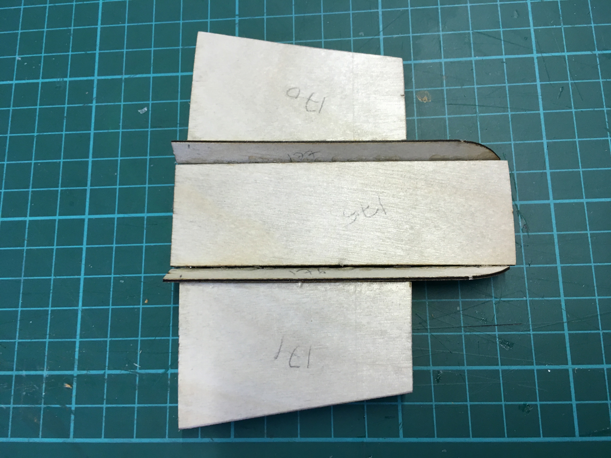
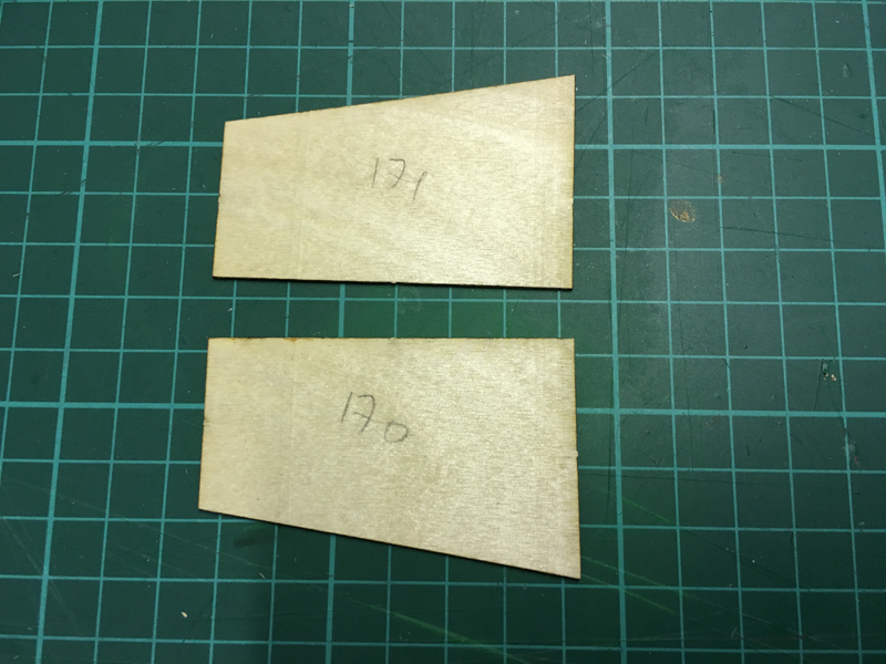
Positioning of planks (parts 175, 76, 177) require some attention. The first photo below is a demonstration of wrong positioning, even though it looks tempting:
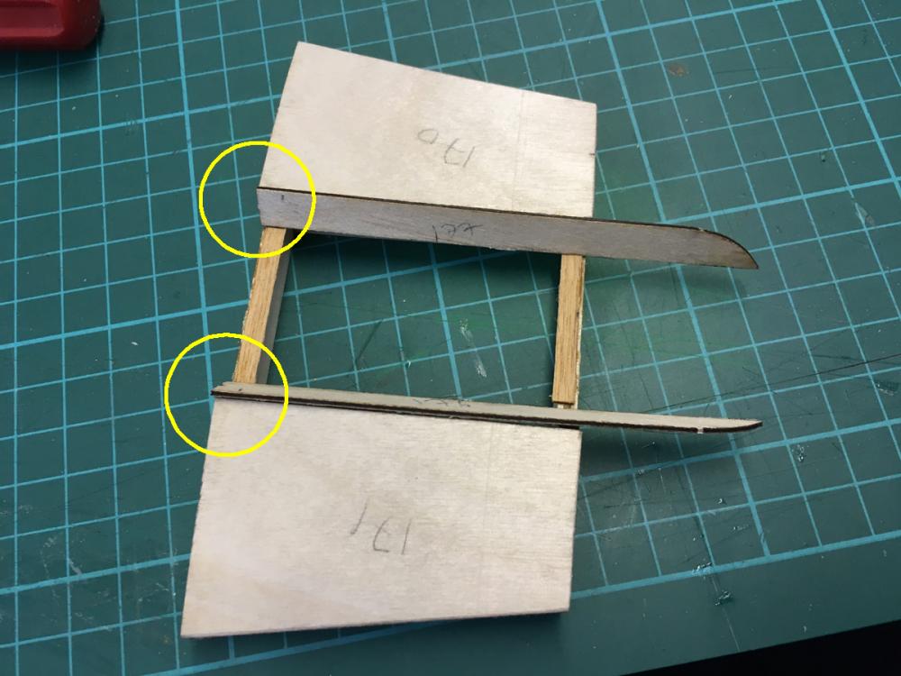
This is the right way:
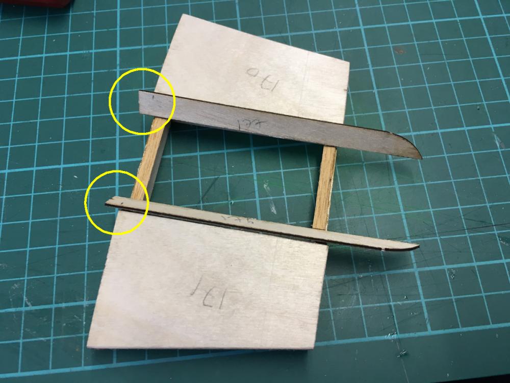
If you look carefully at where the middle part sits, you will notice that I glued thin strips, which will raise the middle piece about a millimetre or so. Without them, the middle piece was touching the stern. so that was the reason.
The middle part in place, all glued:

Lid in place:
-
-
-
-
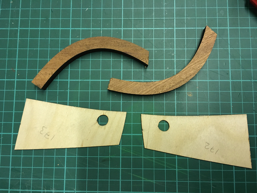
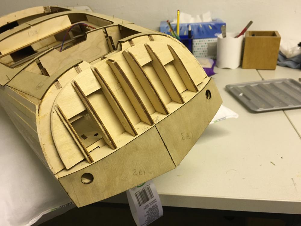
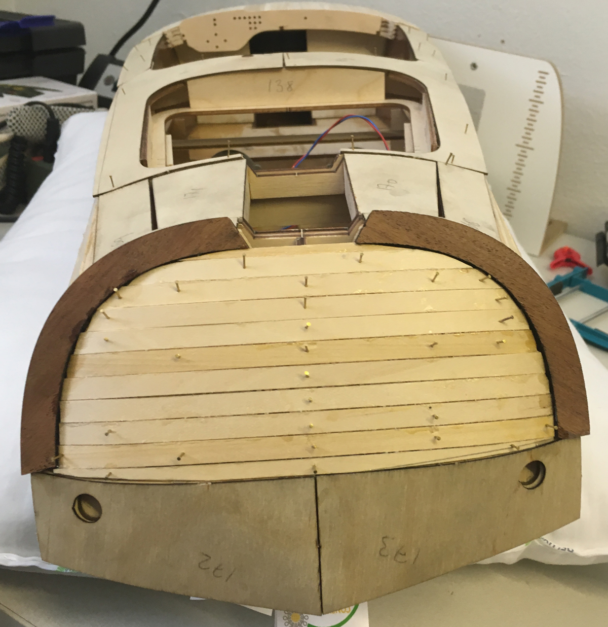
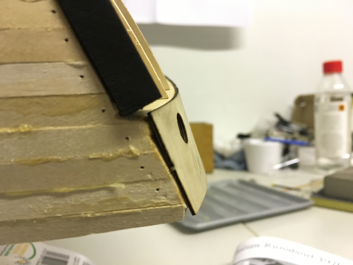
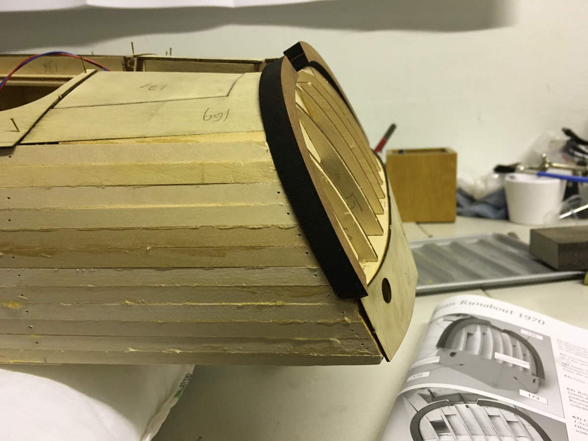
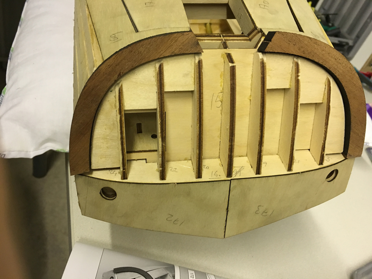
Glued the thick curvy mahogany frame which I had filed ready yesterday. They are now covering around the stern.
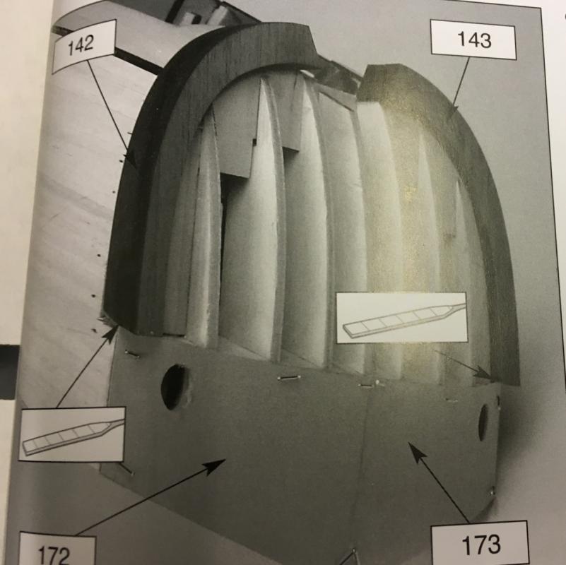
Apparently stern planking should be done in such a way that the 1st planking (which I am doing now using 1,5x7mm lime as the previous plankings) shall be level with the veneer parts on the bottom ( i.e. parts 172 and 173), while leaving some offset with the mahogany frames, so that they will be level with the 2nd planking (which will be done using 1,5x8mm mahogany strips). So I glue them around 1,5mm offset (see the photo):
-
-
-
Aydin,
Why didn't you glue 14C and 14D to the removable part ... or at least the part from them which is above the removable part. You'll be lacking support if I'm not mistaken ...
Hi Carl,
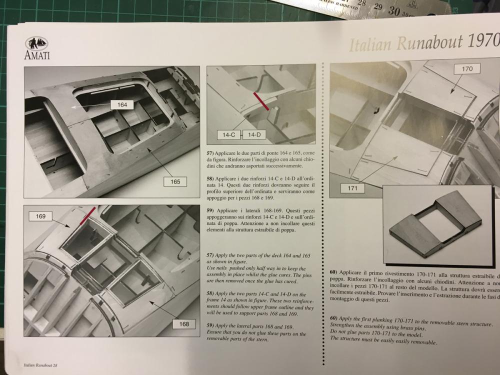
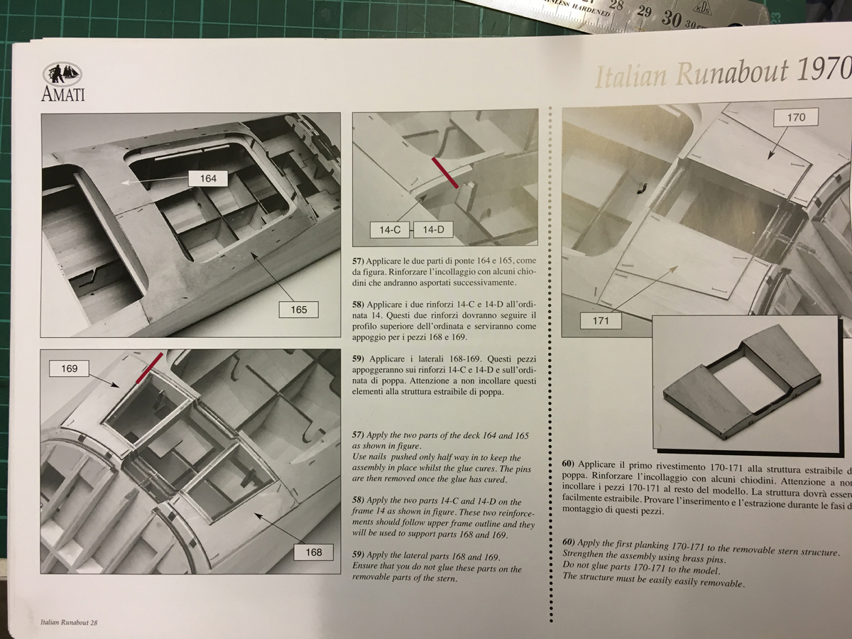
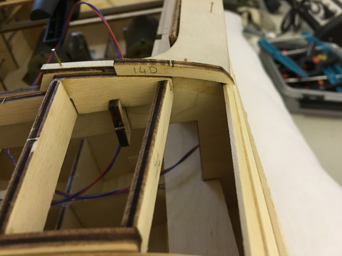
14C and 14D are meant to support parts 168 and 169 with glue. These parts are fixed. According to the instructions, the removable part (actually it is the engine lid) is positioned between them.
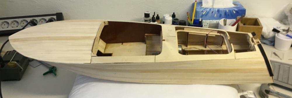
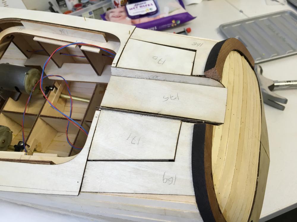
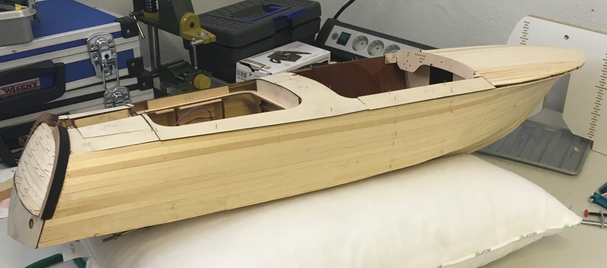
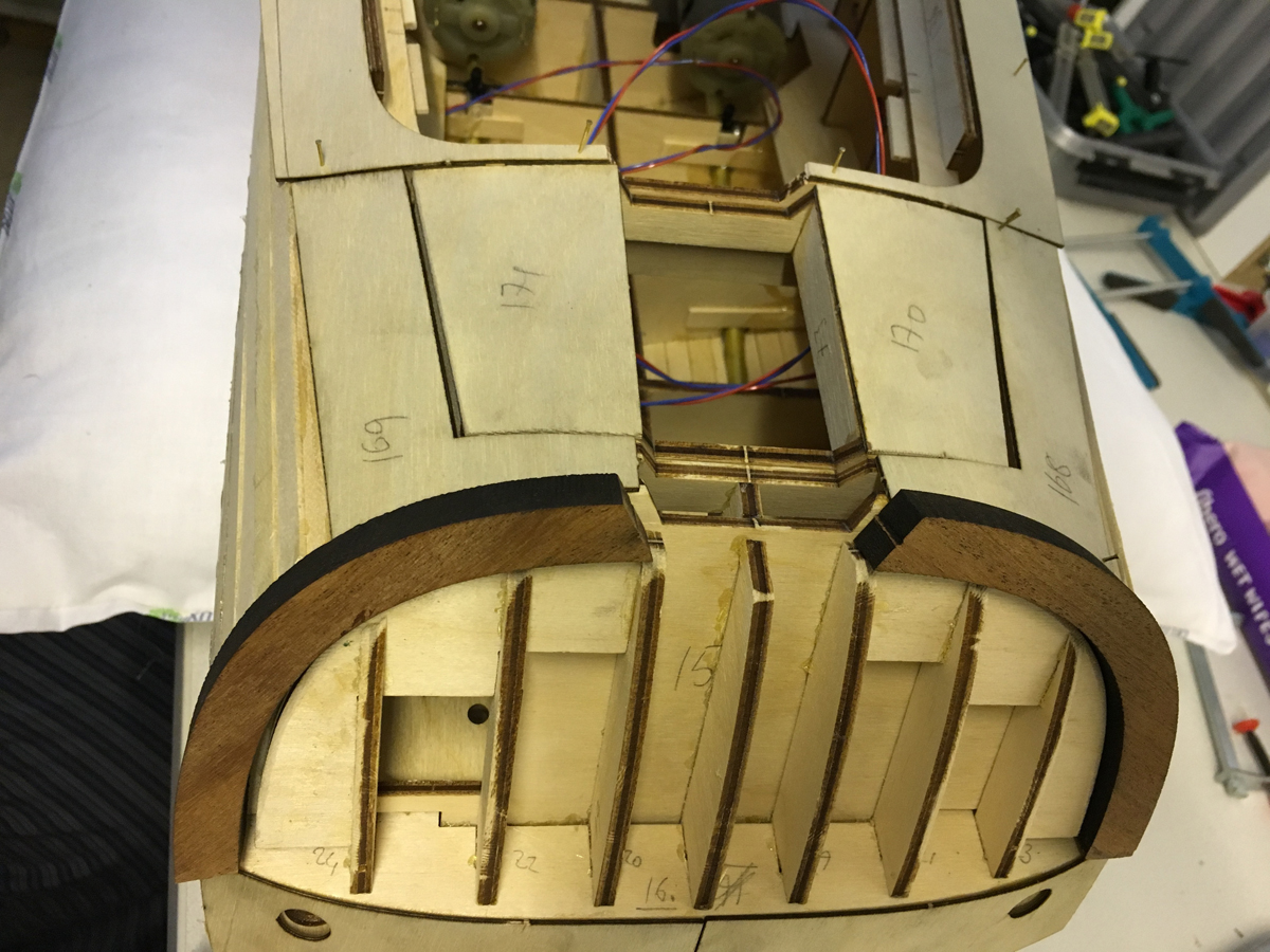
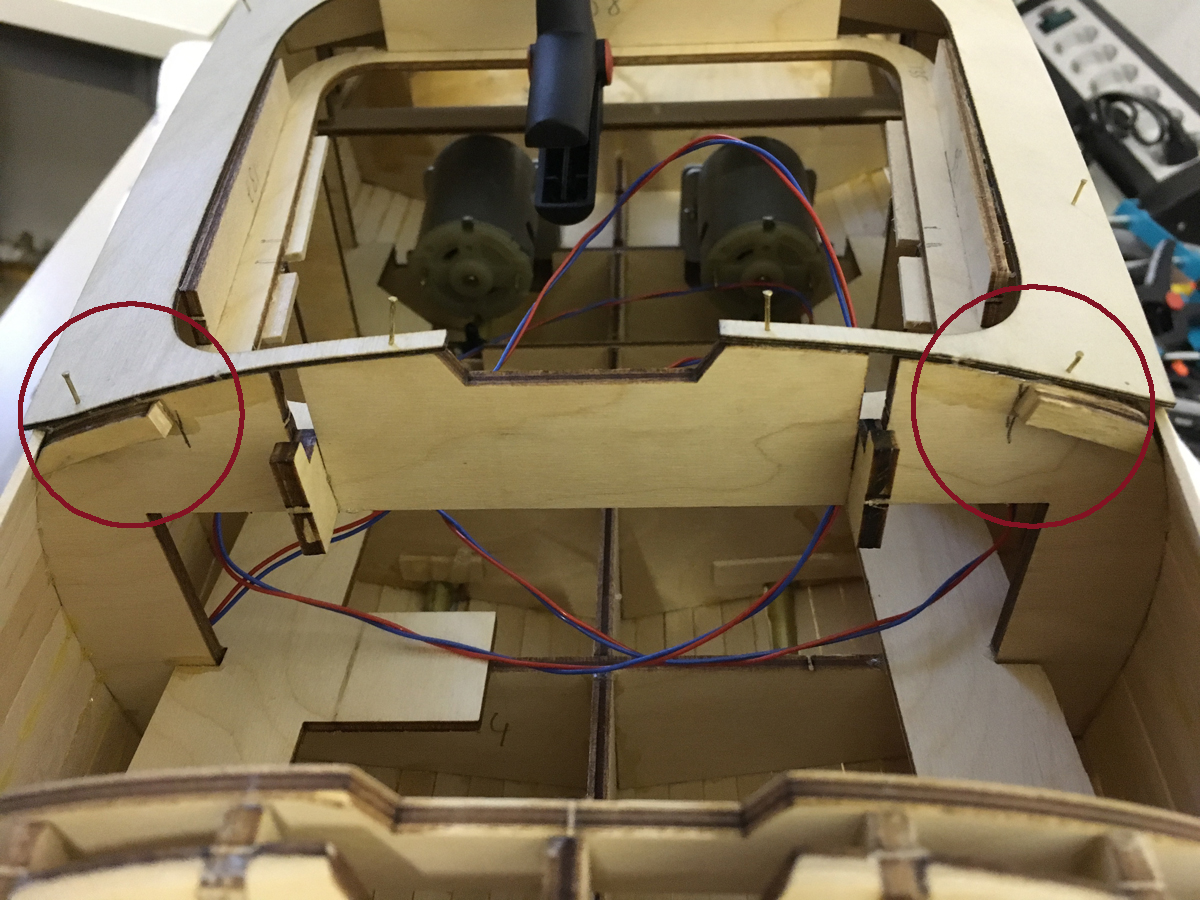
In the photo below, you can see 168 and 169 on the sides and the lid (which now includes 170 and 171) in the middle:
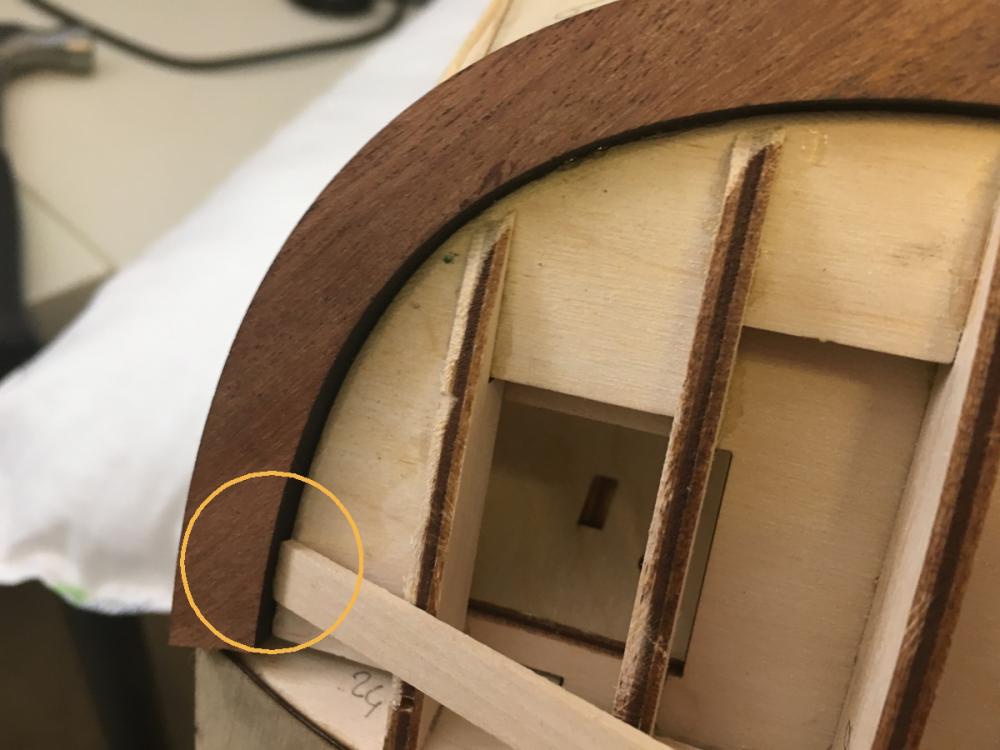
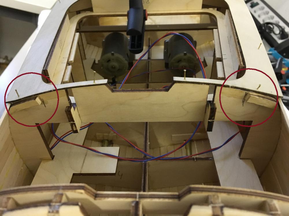
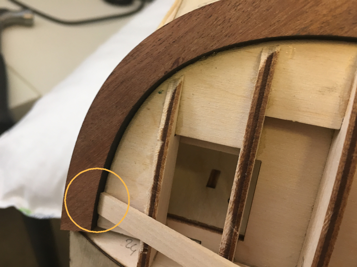
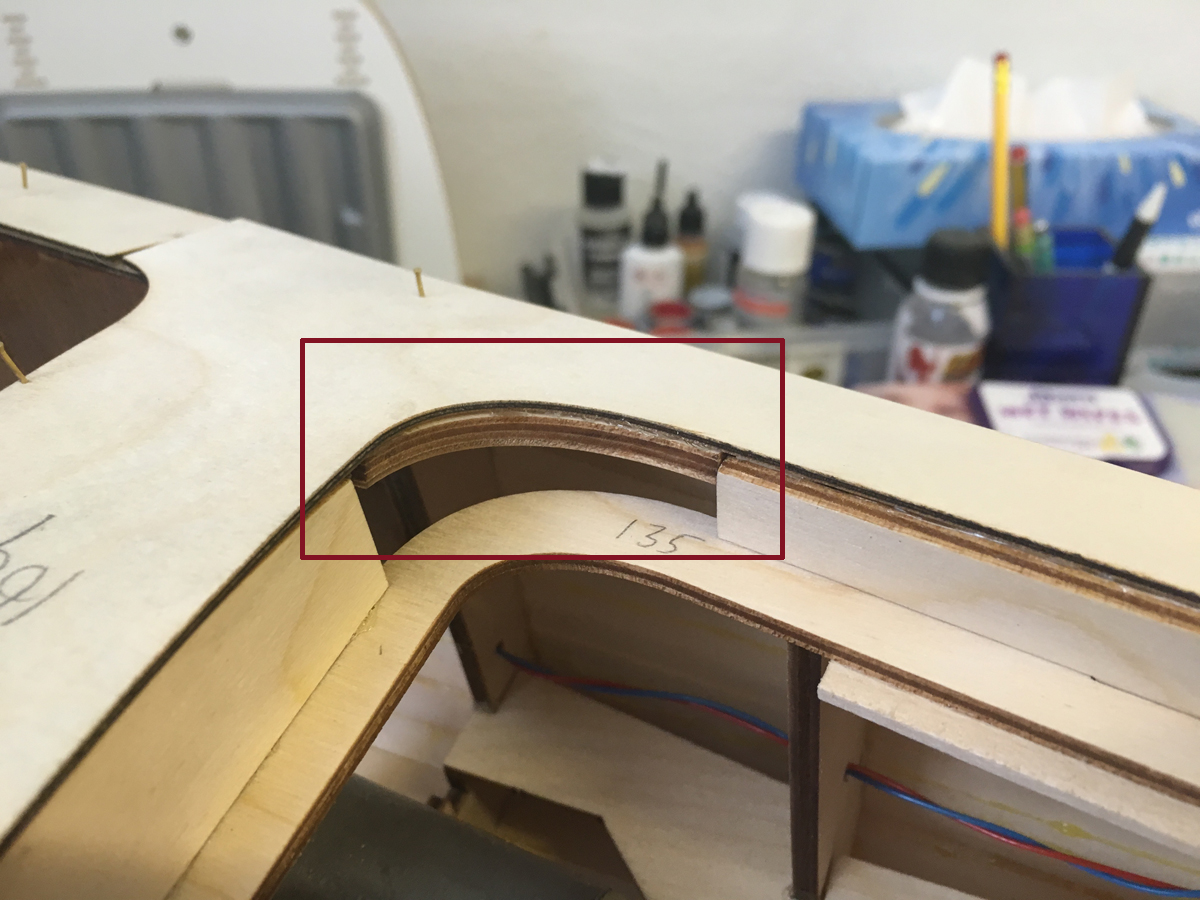
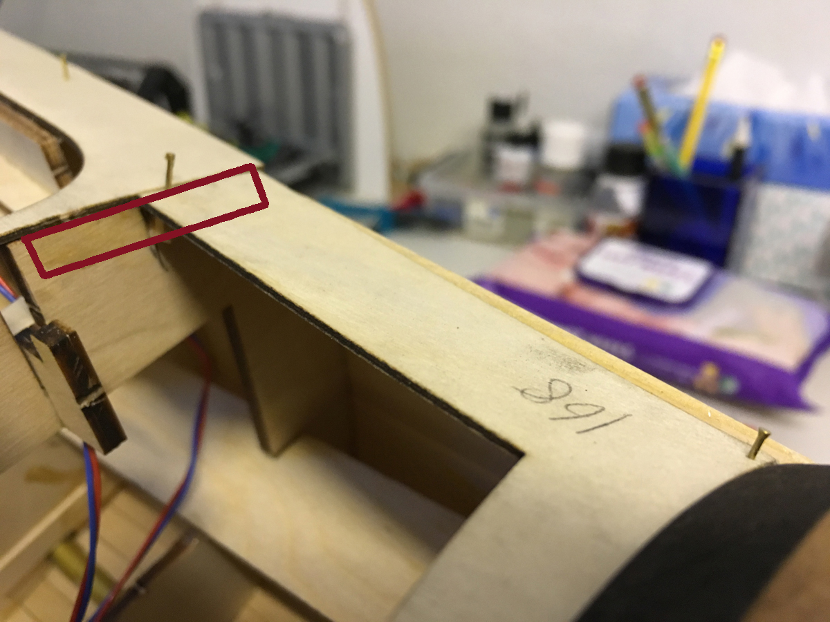
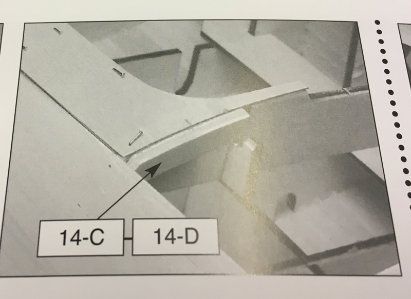
This is the view when the lid is removed (here note that the lid is sitting on the 2 wooden "hooks" inside). The red drawing on the left indicates where the 14C would have occupied if it had been installed as in the instructions (same on the other side). But in that case it is impossible to place the lid anymore.
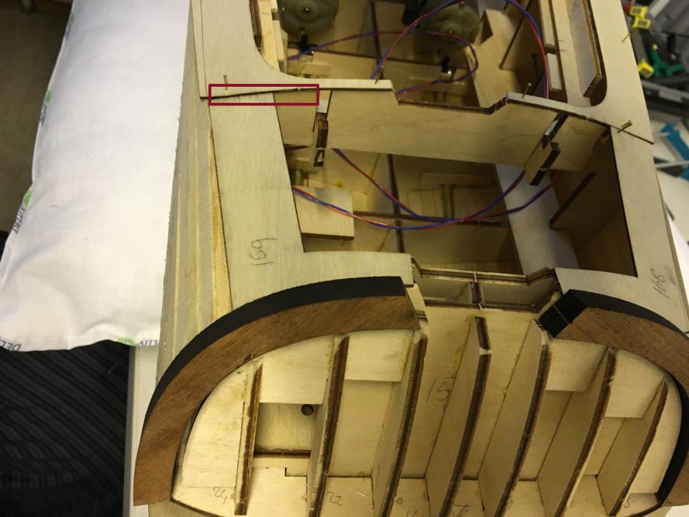

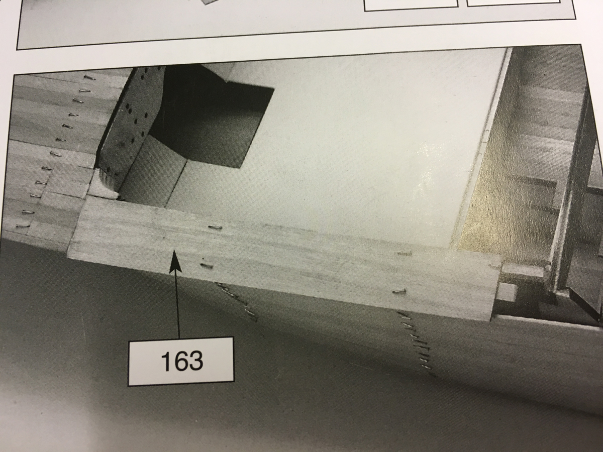
See also the red lines I have drawn on the instructions:
So my solution was to chop off 14C and 14D short enough to stop preventing the lid and long enough to support the side pieces.

-
-
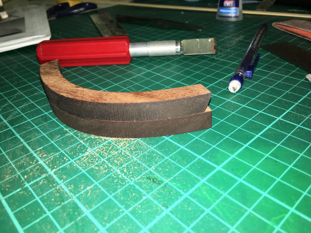
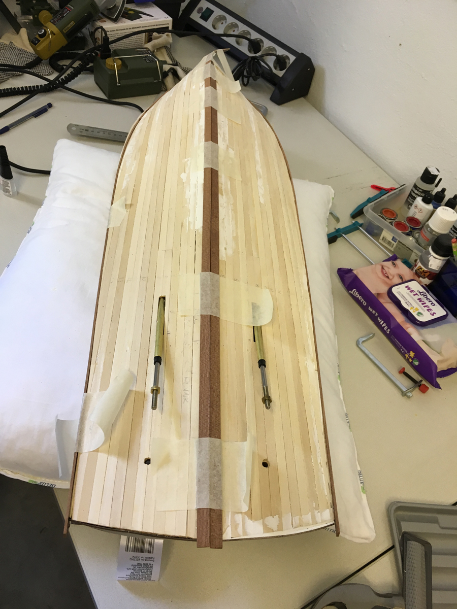
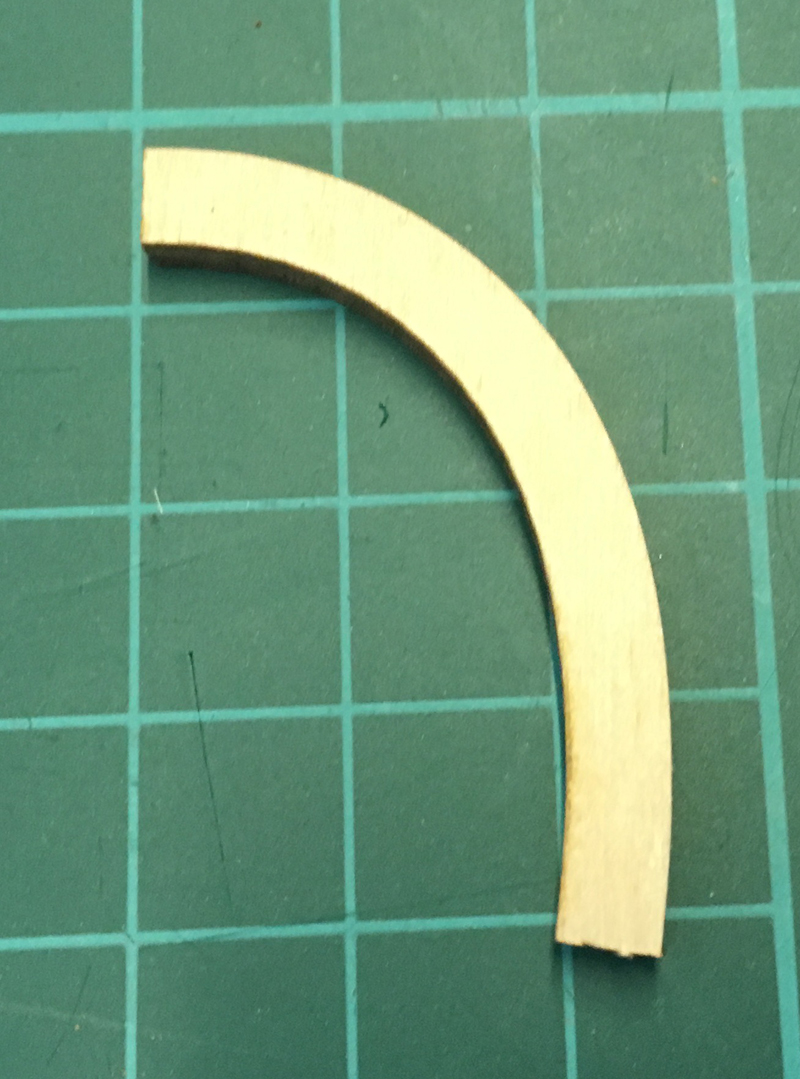
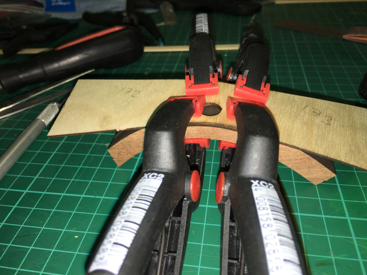
Coverings at the stern. The instructions call for trimming the ends of the thick mahogany arcs with a file to fit the flow of the stern (note the file symbols on the instructions). This sounds virtually unpractical to me since the piece is really thick and there is quite a lot to get rid of. Hence, I used a combination of saw, file, sandpaper, and knife to get the desired result:
Bending the veneer parts on the lower part to fit easily:

Veneers in place:
This is why the mahogany arcs need trimming:

Trimmed:
And dry fitted to place:


-
-
-
-
-
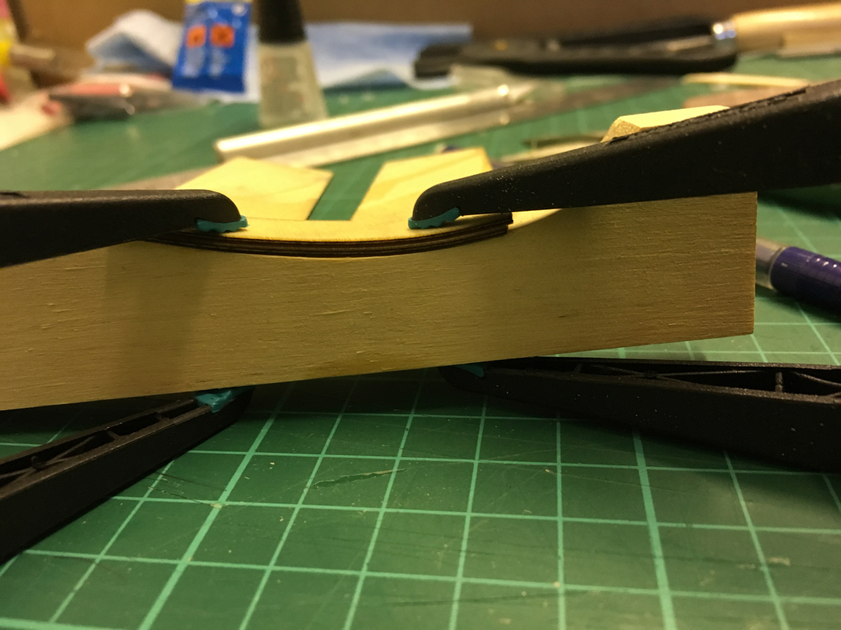
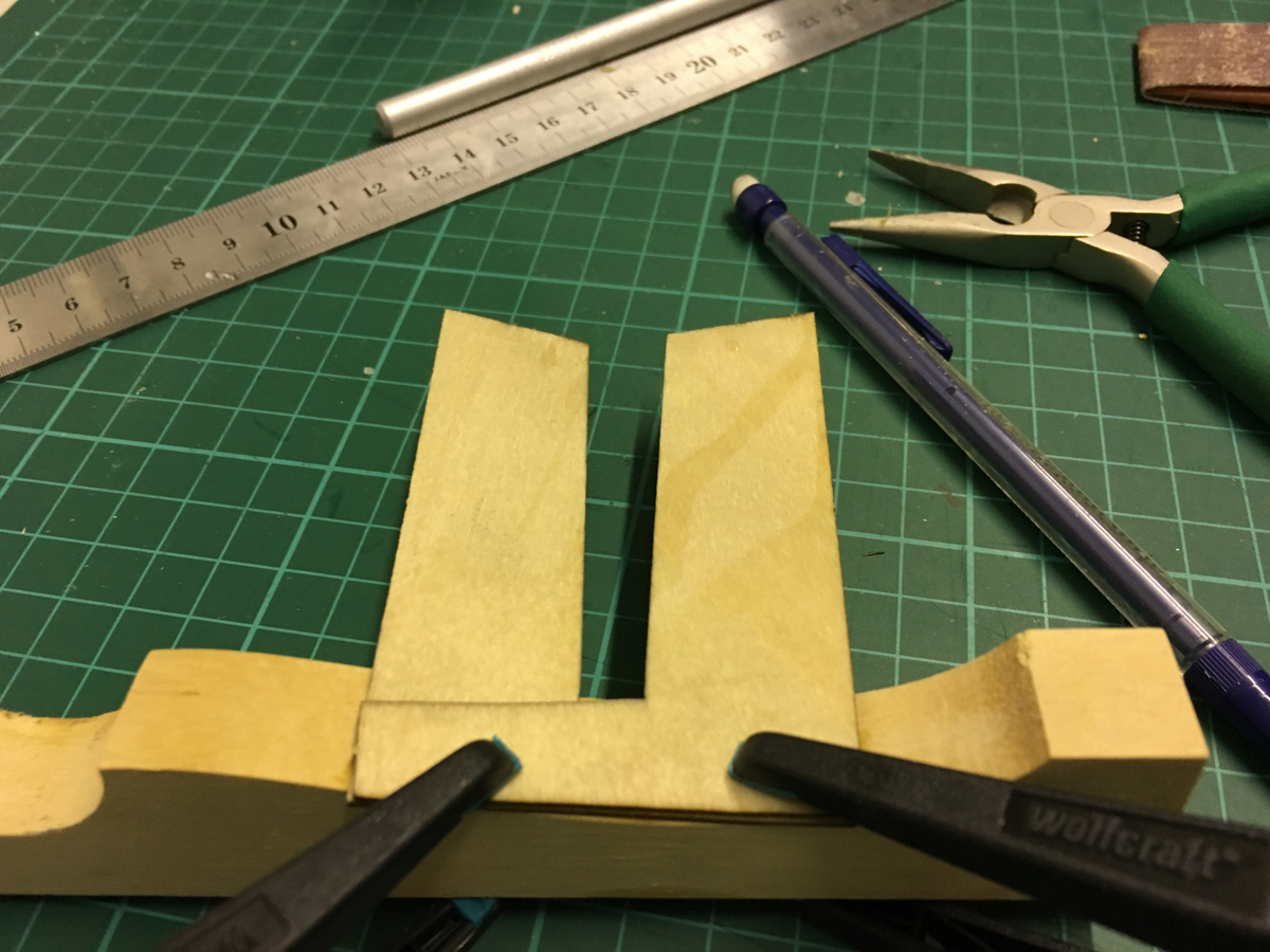
Here I noticed a problem. Check the following 2 photos where I show the "removable" section. In the first photo it is out of its slot and in the second photo it is in place.
Photo 1:
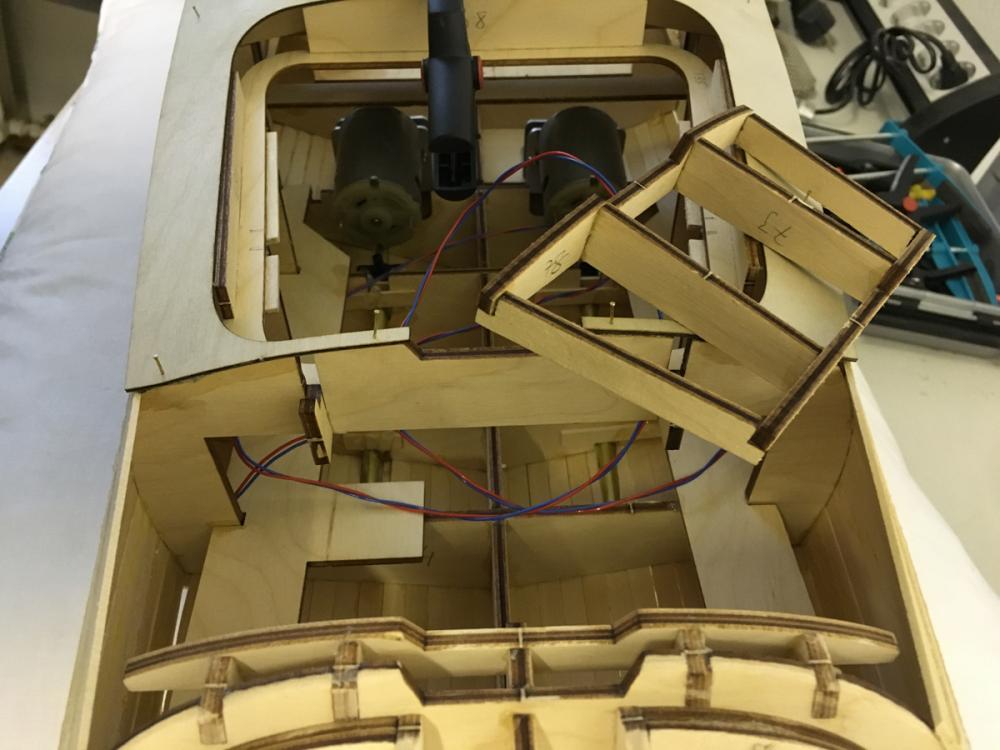
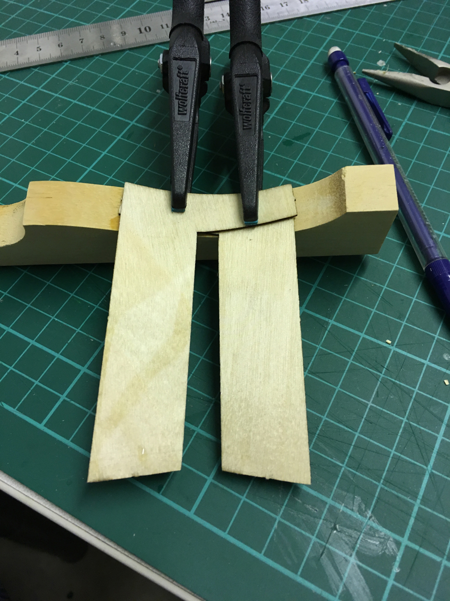
Photo 2:
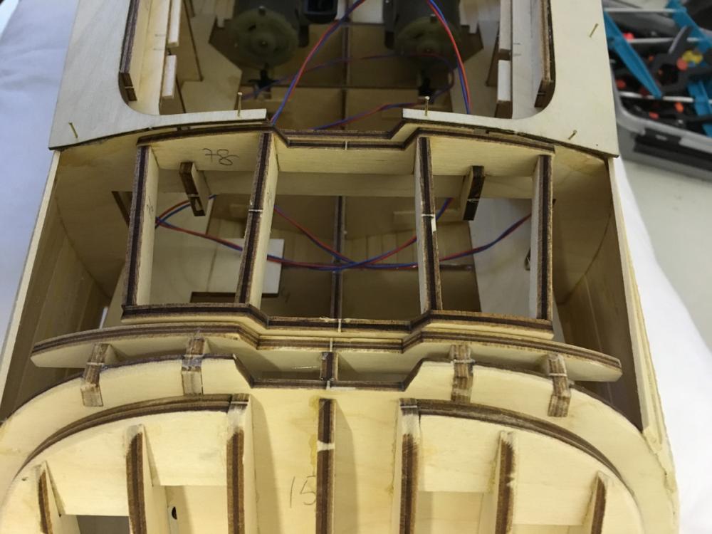
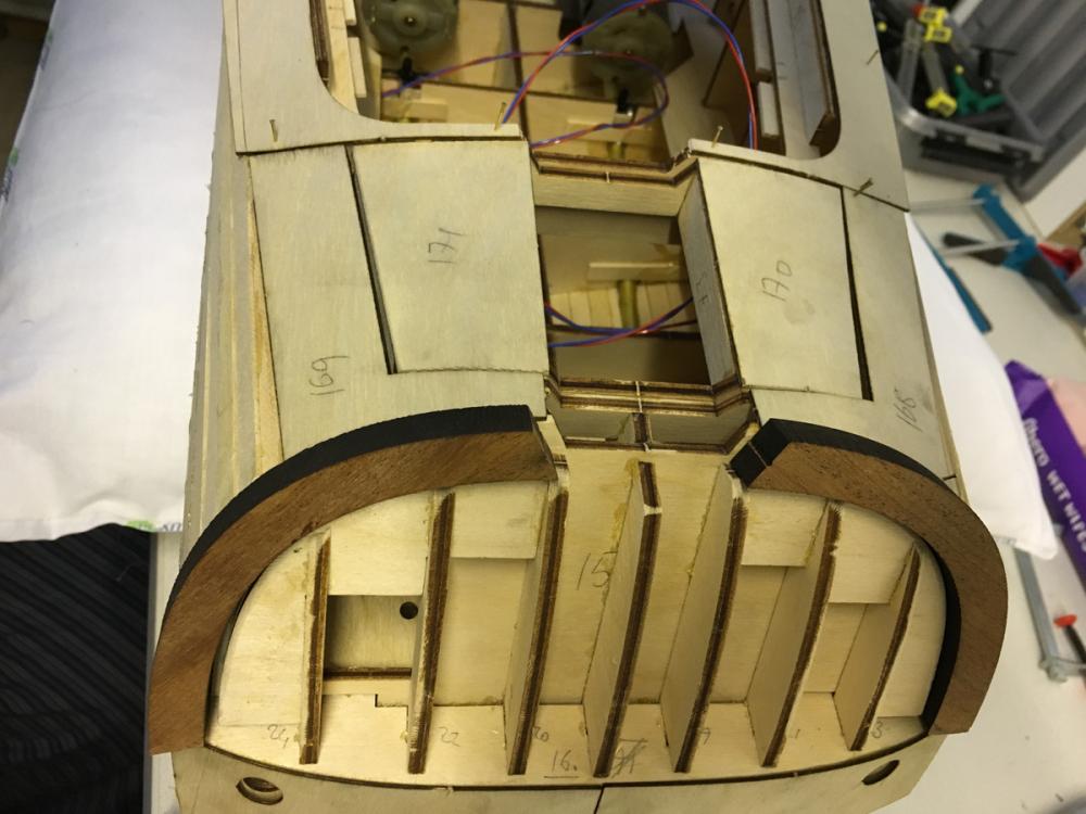
Parts 168 and 169 are supposed to cover the open area on the left and right side of this removable part while parts 14C and 14D are to be glued on either sides to support them. However if you make the mistake of gluing the parts 14C and 14D (like I did - just look at the glue stains), there is no way to place the removable part anymore. Check from this photo how it would have blocked the removable section from placing to its slot:

So I had to cut them short enough so that they won't block the removable section but still support the parts 168 and 169:


Riva Aquarama by aydingocer - FINISHED - Amati - RADIO - A new challenge for a so-far static ship builder
in - Kit build logs for subjects built from 1901 - Present Day
Posted
Sure I will make several tests on scrap wood. You can't rush science... especially on a piece of art