


qwerty2008
-
Posts
552 -
Joined
-
Last visited
Reputation Activity
-

 qwerty2008 got a reaction from Elmer Cornish in Byzantium by qwerty2008 - Scale 1:20 - RADIO - based on the Pride of Baltimore
The Byzantium is now sporting the latest fashion, white gun port stripe black rails and red bulwarks. I still need to apply another coat of red to the bulwarks and do some touchups.
Lextin.
-
qwerty2008 got a reaction from Elmer Cornish in Byzantium by qwerty2008 - Scale 1:20 - RADIO - based on the Pride of Baltimore
I applied the second and third coats to the bulwarks then did touch ups on the rest.
Lextin.
-
qwerty2008 reacted to FreekS in HrMs O-1 by FreekS - FINISHED - 1:32 - RADIO - first Dutch submarine 1906-1920
@Piet, bedankt voor het compliment! As with most ships, fotos indicate many changes made during the boats life. As this was the first Dutch sub, it was a testbed. In fact the drawings I have are of the "mid-life conversion" when the dangerous petrol engine was replaced by a Diesel. The early photos often show two short masts with stripes fore an aft, I think to help trim the boat. Later fotos seem to have three full masts with navigation lights etc.
As my O-1 will be a working model, and those masts were clearly taken down for submerging, I will make the early version with the two "trim masts". As I call them.
Another very visible feature of the boat are the flanges that were used to rivet the deck section and the fins to the pressure hull. Rivets themselves are only visible in dock fotos, I think they were probably hammered flat and covered with many layers of paint.
I cut the flanges from 0.4 mm carton (so in rl they resemble 12 mm steel), and glued them on the boat. Next they were coated in thin 2 component epoxy resin to make the waterproof.
-
qwerty2008 reacted to DSiemens in Byzantium by qwerty2008 - Scale 1:20 - RADIO - based on the Pride of Baltimore
Great work. I'm curious. What are you using to water proof the hull? I have been toying with the idea of making an rc model for a long time and that's one thing I've often wounded about.
-
 qwerty2008 got a reaction from archjofo in Byzantium by qwerty2008 - Scale 1:20 - RADIO - based on the Pride of Baltimore
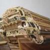
I made a a special block for the main sheet and took a video of how everything works. I am not very good at making videos so be warned it is kinda crummy.
Lextin.
-
qwerty2008 got a reaction from archjofo in Byzantium by qwerty2008 - Scale 1:20 - RADIO - based on the Pride of Baltimore
I made a case for around the drum and also have been working on making a system to double the pull of the servo by putting a pulley on a track. I still need to make the supports for the track and run the rudder control around and out of the way.
Lextin.
-
qwerty2008 reacted to molasses in OGALLALA by molasses - FINISHED - 1/96 scale - BOTTLE - Prairie Schooner
Thank you, Piet and Bob, and the likers and lurkers. I don't mean "lurker" at all derogatorily - I "lurk" several builds and topics myself.
Worked on some odds and ends. I started with some cleats.
Cleats ready to install. They have a piece of bug pin through them for strength when glued to the bulwarks.
Some of the cleats glued into holes and rigged. The crossing ties on the cleats are fakes.
The lines to the cleats will be glued when inside the bottle and trimmed close to the cleats.
Then I finished the foremast yard braces and foresail gaff vangs.
Upper portions of the braces and vangs.
Lower portions of the braces and vangs.
The remaining rigging will be finished when the sails are installed.
I also worked on my trial figure by building it up with some more gesso to the point where I can try to detail it. I discovered that the cured gesso is flexible, almost rubbery, and I can adjust the pose, which may be a blessing - or a problem. I didn't test it to find out how much flexing it will take, maybe later if I don't like the finished figure or replace it with another after some practice making three more figures.
A photo I posted a while back for comparison to the more "filled out" current condition.
A pair from his larboard quarter. I trimmed the legs and will add feet below the cuffs of his pants.
And from his starboard quarter. It seems my photography has improved somewhat in the interval.
Dave
-
qwerty2008 reacted to torpedochief in American Cutter LEE by torpedochief - Revolutionary Era Battle of Lake Champlain
I like this ship! It only sailed in one battle. It was miles from salt water. It was not well built, not for lack of desire but due to being built in an ad hoc shipyard by folks who really did not know what they were doing. She was built as fast as possible. She was a weapon in an arms race with British forces in Canada. The crew; brave as they were had no where near the training to even sail the ship, much less take her into battle. There were not enough guns. The guns they did have were varied, and there was precious little powder to train with.
All the above is the reason I want to build this ship. Those people embraced the cause of Freedom. Although they knew little of ship building, they did it. The crew with everything against them took her to battle with the most professional navy on Earth at the time. They did not win the battle. LEE was forced ashore and abandoned, however her actions along with other hastily build ships tied up the British long enough for the Americans to gain needed time to prepare and rearm.
So those are the main reasons I chose this almost forgotten little cutter. This is my first ever Plank on Bulkhead model, so the learning curve looks more like a corkscrew.
I found the plans for the LEE in SHIP MODELING FROM SCRATCH by Leaf. The plans called for a model that would end up at 16 inches. Don't have that much space and the Admiral even has eyes on my shipyard.......Oh no! So I scaled the plans to produce a model at 11.9 inches no counting the bow sprit.
Now if I can figure out how to put captions on the pictures I'll get you the 411 on my build.
Oh almost forgot. Island Belle is next in line now. I have been assigned a great mentor by the Nautical Research Guild. I was getting to comfortable with solid hulls and I need to step it up!
Looks like I am not that bright. I don't know how to put captions on the pictures So after sizing the plans, the first thing I did was build a ladder out of teak. I don't know why. However it did give me the chance to introduce some of you to a great finishing product, that is also great for tools! Renaissance Wax was developed by order of the Queen for the British Museum. This stuff really means it when the say a little goes a long way! It goes on smooth and hardens instantly. then a soft buffing brings out beauty in wood like you never thought possible. On tools it lubricates and protects. I use it not only in my scrimshaw but on my band saw table, Scroll saw table, and sander. Make anything move friction free and protects the surface to boot.
With the ladder done and waxed I next traced the false keel and bulkheads on parchment and then laid them out on my 1/8 ply. With the false keel cut I reinforced the area where the Main Deck goes to the Poop. This was done since the weight of the aft end is more and the center of force is higher. That adds up to a snapped part if you are not careful. I also cut the mast step.
When the bulkheads were cut and trued I test fitted them. The last Bulkhead tapers way thin near the keel. I cut a channel on each side so the thickness of the bottom of the bulkhead and the thin ply of the keel would work out. First try was close but a little off the mark which I corrected by widening to one size and shimming so the fit would be snug.
The model will be left natural wood as a tribute to those who built her. I fashioned the Keel, Stem and Stern Post from walnut. The scarf joints are not correct on purpose, again to indicate the haste the ship was built in.
I next cut slots into the Keel and the false keel to receive wooden "Tabs" these assured alignment and gave me a very tight bond and providing my surface area for the glue.
Oh Yea!! Those little brass planes you see. I picked those up at Harbor Freight $10 for the three. Let me tell you, these things are just wonderful to work with, and too look at.
Once dried I proceeded to try cutting rabbets. I ground down the tip of a #11 blade. I made a line along the keel and a bit at a time removed the wood. Three hours later and with 600 grit paper to smooth it out the rabbets were done. SCORE!!!
Next I trued the bulkheads and using my FAIR A FRAME (Which I do not care for in the least,) I glued in my bulkheads. Oh no first timer here... gonna be a disaster! Nope. Everything went in square! How I did that I will never know and most likely will never be able to again. I strengthened the bond with four small piece of bass wood where the bulkhead transverses the false keel. Using such small ply I beefed the whole frame up by using 1/4 basswood. I alternated the how the supports met the bulkheads to spread any stress while planking and what ever time and humidity can do to my little boat.
All for now my sisters and my brothers .
-
qwerty2008 reacted to threebs in Pennsylvania by threebs - 1/72 scale
I have been working on the yards a lot lately. There is a lot more to do than I remember from my Victory Model 30 years ago. I am trying to get as many blocks as I can on the yards before installing them. As this ship will not have sails, I do not need the leech or bunt line blocks, so I will be leaving those off. Everything attached to the yards needs to be served, and attached primarily with rose lashings (or a close approximation). I made the slings as you can see, and I am making the trusses now (no photos of those yet). I am also putting on shrouds at the top gallant to royal yards tressel tree. I will post photos of how I attached them later. I also made and sort of installed the spanker and gaff booms.
I apologize for the messy deck, I will vacuum it clean when I finish installing the yards. Once the yards are done, I think all that is left is the anchor assemblies, the davits, and the ships boats???
-
qwerty2008 reacted to Bedford in Maine three-masted schooner by Bedford - 1:54 - RADIO
The weather was kind this weekend so I got the work done in the garage.
I had to make them in two halves so I can fit them around the masts and glue them in place without having to unship the shrouds etc and lift the masts out, I have to do that later.
I made the two halves for each station and drilled the holes for the masts at 86degrees and the holes for the sail controls vertically.
The biggest drill bit I have is 12mm and I needed 14mm for clearance in the hole so after goning to the hardware store and seeing that they were over $70 I decided to give that a miss and find another way. Eventually the penny dropped, LATHE.
I turned some bar down to 14mm and then a smaller shank to go into the drill chuck and because I already had 12mm holes I tapered the cutting end down so the bit would self centre in the hole. Then I just cut two grooves into the stock to form the cutting edges of the flukes and filed the excess away ahead of the flukes to provide a cutting edge.
Set the drill bed back to 86degrees and bore out the holes to 14mm. easy.
Bracket made
In place around the mast with the pipe for the cord to run through back to the servo
I was concerned about having a smooth fair leed for the line to run out and in this case it will run through a sweeping arc from side to side each time she tacks so I can't run the cord over a cut brass edge. Luckily I have glass beeds that fit very nicely in the end of the larger tube size I bought to use to make couplings for the control plumbing. I will cut the larger diameter piece into 15mm lengths and glue a glass beed into the end, this will then just slip snuggly over the smaller tube that protudes from the deck. The beauty of this is that I can remove it and attach a vacuum cleaner over the control tube to draw replacement lines through without it getting caught on a restrictive fair leed placed inside the control tube.
-
qwerty2008 reacted to bensid54 in Greek Bireme by bensid54 - FINISHED - RADIO
This post shows the bulkheads during alteration. What appears to be a drill bit is actually a cutting bit that can do a lot of destruction in a very short time so I had to use two hands for this part in case it went astray. One picture shows the type of cut this tool does very quickly and very roughly this of course is the initial cut. The other pictures are the result of sanding with a Dremil barrel sander and finally the one picture shows the keel cut away to fit the batteries and two servos. Next the mechanics and now that I have a final design worked out I'll keep you posted.
-
qwerty2008 reacted to FreekS in HrMs O-1 by FreekS - FINISHED - 1:32 - RADIO - first Dutch submarine 1906-1920
Subsail is over again. The technical bits of hr ms O-1 were finished on time and seem to work.
However, the boat has not seen water yet as its unpainted. My other boat (K-XVIII) did get into water and even fired a torpedo but I had little chance to film in the pea-soup like water.
On a short holiday in Switserland I took a box of tools, including my 15 W soldering iron.
So after mountain hikes I could make some of the details.
First the steering wheel, in the case of O-1 mounted outside the conning tower and horizontal. The coin for scale may be unknown to some, as the Dutch have discontinued it but the Germans have not.
Here is the completed steering wheel, and the mast. This submarine from 1905 still had three masts (plus two periscopes).
Also these old boats had lots of details, here a few thingies for tying ropes to, foundations for the fore and aft-masts, and guide-eyes for the (anchor?) chain (I have not found out yet if the O-1 had an anchor)!
Greetings Freek
-
qwerty2008 reacted to molasses in OGALLALA by molasses - FINISHED - 1/96 scale - BOTTLE - Prairie Schooner
Welcome back.
Worked mostly on foremast rigging. Since most of this work is repetitious of the mainmast rigging I won't go into the details of how it was done.
Foremast with most of the rigging - and looking like a birds nest. It's
easier - and safer - to rig as much as possible of the mast off the model.
I took this photo right after stropping all the blocks while waiting for the
glue to cure so I can trim all the loose ends.
Foremast in place with the standing rigging and ratlines rigged. Also in place
are the gaff with throat and bridle halliards and vangs. The bird's nest is slowly
being un-tangled with lines going down to the deck and tied off to the pinrails.
Close-up of fore topmast, gaff, crossjack and topsail yard. You might notice that the
topsail yard and crossjack halliards pass through the tips of the yards to become
the respective braces. The lines are not glued at the tips, only at the mast. This
arrangement allows the yards to rotate to a position more parallel to the mast
after the mast is hinged down to the deck for fitting through the bottle's neck.
Another view of the crossjack and top. Note that the running rigging is in four shades
of tan to simulate varying states of wear and weathering. I still have the topsail yard
halliards and the topsail clew and buntlines to route to the deck and tie off. That will
leave the other ends of the clew and buntlines left hanging until I bend the topsail.
Overall view of the progress so far. I didn't forget the ratlines on the main topmast shrouds, I left them off
because they were frequently omitted on schooners like this. I also have the fore braces and vangs to rig.
Dave
-
qwerty2008 reacted to marsalv in Pandora by marsalv - FINISHED - 1:52
Hi Antony,
thank you for your compliment .
I continue with the production of external keel. It is made of individual parts which are glued together.
-
qwerty2008 reacted to marsalv in Pandora by marsalv - FINISHED - 1:52
The bulkheads and the inner the keel is made of plywood, the outer part of the keel will be made of pear wood. Thanks to the large number of bulkheads (26 pcs) and small gaps between will be done only one planking.
-
qwerty2008 reacted to Piet in Hr. Ms. O 19 1938 by Piet - FINISHED - scale 1:50 - submarine of the Royal Navy Netherlands in service 1939 - 1945
What I should have added yesterday is one more reason for me having the gantry boom hanging kinda low is that I need to run antenna wires over the top of the gantry. Normally, when loading a torpedo the boom is pulled up to a higher angle, of course, to get a good loading angle on the torpedo. I don't know yet if I'll change things later on to show the torp actually being in the process of sliding into the loading tube below deck. That would really be the cat's meow but then I would also need a bunch of characters on deck handling the operation and that's not in the plans - - - so far But one never knows - - - - - -
Today has been very slow in the dockyard. I have been mulling things over to what project / model I should tackle next. I have been procrastinating the propellers for many months now and think it's time to cut the mustard - grab the bull by the horns - and make the props. I'm really a little apprehensive tackling this difficult project. But then again, I have enough copper sheet so I can botch-up a lot of blades.
As I was thinking and thinking I made a proto shell for the deck gun. I wanted to see what was involved making a bunch to fight off those large and heavy guns from Sjors and Mobbsy and perhaps a few others who want to do battle
I know, they need to be a little smaller and the grenade more pointy but the idea is there. At least I don't have to make powder bags, water mops, stampers and steel balls
I have not filled the shell with black powder (yet) so it's still a dummy ((like me ))
One thing I see is that I really should use brass for the shell casing, copper won't do. But it's just a prototype.
Thanks everyone for visiting and your likes, it's really very encouraging.
Here is the prototype deck gun shell standing on the deck next to the loading breech. I still need to add the outlines of that on the gun.
This is a plastic boat from my Thermopile clipper kit to hang it temporarily on it's boom. I was tired of seeing a socket wrench hanging off the hook.
Cheers,
-
qwerty2008 reacted to amateur in Hr. Ms. O 19 1938 by Piet - FINISHED - scale 1:50 - submarine of the Royal Navy Netherlands in service 1939 - 1945
I still don't understand why the rigging of the dinghy-boom does not match your drawing.
There seems (at least to me) more logic in the drawing than in the current state....
btw you're going into a dangerous direction: lots of work is going on on deck (shells, boats, mines, torpedo's),
you'll need a real crew before long
Jan
-
qwerty2008 reacted to Piet in Hr. Ms. O 19 1938 by Piet - FINISHED - scale 1:50 - submarine of the Royal Navy Netherlands in service 1939 - 1945
Well, let's see - - - what did I do today, oh yeah, drove to the eye doctor for my annual check but it was a no show and had to reschedule it for after the 4th of july. Gwen and I will be in Coraopolis, PA visiting our daughter and grandson for two weeks - - - yippeeee. We are leaving next week Tuesday. Gwen suggested that I bring my big-screen iMac with me then I'll have all the pictures in my archive to show Troy, our grandson. He's totally impressed with his great grandfather and what he's done.
I had plenty of time before lunch and started with the propellers. I first made a card dummy prop blade to use as a template. Transferred the outline to my 0.6 mm copper plate with a steel scribe. Then, using my jeweler's coping saw with a metal cutting blade, cut them out. Yep, it's a slow process but using tinsnips would curl the metal too much and I want the curl to be my way, not what the tinsnips give me.
After I had the rough pieces in my hand then I used the tinsnips to cut away the parts outside the scribed lines. Then I used a file to file it to the scribed line and cut a small "pins" into the bottom of the blade to assist it in cementing the blades to the hub.
I then bend the curved profile in the blades by hand and eyeball. Remco send me a few drawings of the blades and their profile but by using thin copper I cannot actually carve blades to match those on the real boat. However, I think they are shaping up quite nice. I did some extra filing to at least give it some of the profile.
I carved four small diagonal grooves in the hub to receive the blades and drilled the holes for the "pins." The hubs are oak and quite hard so I used a small broken drill bit as a router in my Proxxon hand tool which worked great. I try-fitted two blades and it seems to look okay.
So far I only made two blades for one propeller, six more to go.
The filing left quite a few marks on the copper so I'll have to do some serious dressing and polishing but that's all part of the process and fun.
I still need to reduce the length of the blades so there is still a lot of filing yet to do before they fit.
Here are a few pics I put for my archive. Enjoy.
Here is one of the hubs with two blades. They are already pre-bend into their pitch, there is still some bending and twisting to be done before I'm happy. This gives you an idea of what I am talking about above. I still need to drill the pin holes though.
Here I have propped up the hub on a piece of copper tubing and pressed one of the blades in a groove.
Cheers.
-
qwerty2008 got a reaction from Elmer Cornish in Byzantium by qwerty2008 - Scale 1:20 - RADIO - based on the Pride of Baltimore
I ordered the battery yesterday it should be here within the next few weeks. I also took some better pictures of the block which is my first successful piece of brass work. The problem I kept having was that the solder didn't want to stick to the metal. Turns out that I was getting the metal to hot, when I lowered the temperature the solder worked perfectly.
Lextin.
-
qwerty2008 got a reaction from Elmer Cornish in Byzantium by qwerty2008 - Scale 1:20 - RADIO - based on the Pride of Baltimore
here are some pics of the battery and my new servo tray layout marked with sharpie. I could not get the battery beneath the servo tray as per my original plans so I put it behind the main mast, it will be difficult to get in and out but it will have to do.
Lextin.
-
qwerty2008 reacted to shipmodel in Queen Anne's Revenge 1710 by shipmodel - FINISHED - 1/36 scale
Hi again, and best wishes for a happy Friday the 13th –
Thanks for the compliments, likes, and wishes for my new grandson. Caleb and his mother are both doing well and send their thanks as well.
Several smaller items were completed in this segment. The first was the forward bulkhead for the captain’s cabin. There are no plans or drawings of it in either of the plans that I am using, so I designed it to be functional, using some of the same details as on the stern and quarter badges.
There is a chair rail molding with wainscoting below. This was not scribed but laid up from individual planks. The door is of a typical 17th Century style, with H-L hinges and decorative cross banding. The windows are flanked by fluted columns which were built up as before. To each side there will be a ladder to the poop deck, which have not yet been constructed. The bulkhead is still removable at this stage, and may have to be moved back a little to give me room to install the whipstaff which will go between the cabin and the mizzen mast.
I have not decided whether to paint the wainscoting blue and add some decorative details. What does the group think?
The cabin was also dressed up by closing in the aftmost gunport with a decorative shutter. The central circle was made by stiffening a 1/8” birch dowel with a drop of thin cyano on its cut end. When dry the center of the dowel was drilled out to a depth of about ¼” and then the circles were parted off on the table saw.
Next I turned to the first of the rigging fixtures – the staghorns. Here is a section of my plans for the inner bulwarks, which was made by using PhotoShop to combine the plans from the Advice Prize with details from Le Mercure. You can see three of the four staghorns that will be mounted on each side.
Here is an enlargement of the plans for the staghorns. Note in the side view the extreme angles that have to be used to match the 13 degree tumblehome of the bulwarks.
I started by carving a length of pear to the shape of the horns of the fitting. The piece was just under 3 inches long, which gave me extra material for the next model as well. Here you can see three horns that have been parted off. They are a little heavy, but were later reduced with a small sanding drum.
The shelf that supports the horns was built up in two parts. In the larger, back piece, two notches were nibbled out for the horns before being closed in by the front piece. In the insert enlargement you can see how the curve of the table saw blade gave me an angle to the back of the notch that is needed to allow the horns to angle to match the tumblehome.
With the horns inserted in the shelf the bottom piece had two notches hollowed out in its back face for the lower ends of the horns.
The lower piece was flipped over and the horns glued into the notches. The lower piece was then sanded to its clamshell shape and the upper ends of the horns were refined to angle up and out. You can see the differences from the left fitting to the completed one on the right.
Here you can see a finished staghorn sitting on an angled scrap block to check that the shelf will be horizontal when mounted on the bulwark.
Here is the complete set of eight staghorns for the first model.
And here is the first one mounted in the waist ready for the lines that run through the hull sheaves for the main and spritsail sheets.
Next I turned to the gunport lids for the open gunports on the port side of the ship. I have detailed their construction before in the section on the test gun station. This one is for the forwardmost port, which is why the planking runs at an angle to match the hull planking. The hinge straps are blackened brass strip secured with three iron pins. The ends of the strips were ground to about half their width so they could fit into mounting holes in the hull.
The strips were all made to a uniform size in a simple jig. A brass strip was trapped between two guides and the locations of the holes for the mounting pins was marked off. Once the holes were drilled the strip was clipped to length at the edge of the jig. I found that without pre-drilling these holes it was nearly impossible for me to drill them cleanly once the hinge strap was mounted on the gunport lid.
Each lid was marked for its proper location and the mounting holes were drilled just above the open gunport. With the lids slid into the holes the brass could be gently bent so every lid was at the same angle. This will be a significant advantage once they are permanently mounted, as they will be much less prone to snapping off when I bump into them (which I am sure that I will). Here they are towards the bow - - -
And the stern.
To check them, I set the guns in place. Here is what they look like in the waist as seen from outboard - - -
And along the length of the ship.
Finally, the entire broadside.
I was happy with the look of the model, so the guns and gunport lids were removed to safe storage until the interior deck fittings are built and mounted.
The first of these was the riding bitts for the anchor cable. As you can see from the plans it incorporates the 5-sheave post for the rigging to the ramshead block that raises and lowers the foreyard.
Construction was straightforward, with each piece cut and shaped, then notched and pinned in place. The sheaves in the post are non-working, and made by drilling 5 pairs of holes through the post with a 0.040” drill in a miniature drill press. The bitt was then put into a Dremel and the sheave slot between the holes was carved out. Care has to be taken to allow for the right-hand torque of the bitt, but a little practice yields good results.
The next rigging fitting that I turned to were the multiple cleat ‘logs’ that sit just aft of the fore and main masts. These were discussed earlier in the build log as well.
Construction here was straightforward as well. Once the dimensions were decided, two pieces of cherry were cut and the ends finished with slopes. The underside of each was sanded to match the camber of the deck. Ten slots were cut in the underside for the lines to run through. It is quite probably that these slots would have been radiused on each side of the log so the line would run smoothly under the fixture. The upper corners of the log were eased as well, as recommended by JerseyCityFrankie. Matching photoetched brass cleats were obtained from Bluejacket, blackened and mounted.
Here is the one on the quarterdeck aft of the main mast. It looks good as is, although I clearly have to clean the deck which is getting very dusty.
Finally, to check that things are headed in the right direction, and to give my spirits a needed lift, I mounted the decks and the lower masts. Hull construction and detailing have taken much, much longer than anticipated, but I can see some light at the end of the tunnel. I just hope that it is not the oncoming train known as “RIGGING”.
Be well
Dan
-
qwerty2008 reacted to Dziadeczek in Can anyone recommend a miniature hand plane?
I have these two and they are excellent
-
qwerty2008 reacted to molasses in OGALLALA by molasses - FINISHED - 1/96 scale - BOTTLE - Prairie Schooner
Welcome back.
Thank you, Jeff and Michael, you are both very generous. BTW, I proudly stole every one of "my" techniques - thank Donald McNarry and Lloyd McCaffery for many of them.
I started with the breast backstays, each rigged with a single and double block. After choosing the length of the tackle from outside to outside of the blocks I routed the thread between two pins in drilled holes in a scrap of wood and built the tackle using the discs as previously described then needle spliced an eye around each block and added the backstays to the model.
I rigged the main ratlines using a "harp" with ratlines spaced and glued to wooden frames. The frames were opposite hand, one for each side of the schooner. After pinning the frame in position with bug pins I glued all the intersections. I'm trying out artist's matte acrylic fixative instead of thinned white glue and am pleased with the results. The white glue sometimes goes milky while the fixative stays clear. I thinned it a little by using a wetted brush when I dipped it into the fixative.
"Harp" pinned in place with intersections fixed and frame ready to cut from the ratlines.
Starboard side has the harp removed but the excess on the ratlines un-trimmed.
Breast backstay and trimmed ratlines. The backstays go through the same hole where the
topmast shrouds were secured and are now tensioned with weights. The backstays need a
bit of adjustment before they glue. After this photo I rigged the futtock shrouds and
futtock staves then glued and trimmed the backstays.
Starboard view of the mainsail, spars and rigging. While assembling this I had a card stock sail
in place, tied to the boom, mast and gaff to hold them in their correct positions. This card stock
sail has been lengthened slightly along its leech (aft edge) to give the belly I want in the sail. The
aft ends of the boom and gaff have a thread to pull that belly in this temporary sail.
Larboard view. The card stock sail will be removed later to use as a pattern for making the sail.
The black line will be removed before the sail is installed. I have some cleats to make and install
where the leads from the blocks and tackles will tie off which explains some of the stray threads.
Close-up of main top showing the futtock shrouds and futtock staves. I used a needle to pass
each futtock shroud through a lower shroud, glued it (not ca) then passed the needle through
those intersections, sideways, for a third thread to be the futtock stave, glued it and trimmed.
Close-up of main top showing the boom and gaff halliards and gaff throat halliard. After making
and installing the throat halliard and installing the gaff I routed the throat halliard and the boom
and gaff halliards through eyebolts installed while building the masts. The blocks for boom
halliards were made in place. The block on the gaff bridle halliard at the eyebolt was glued
prior to rigging to act as a stop while rigging. All four lines continue to the deck.
Close-up of pin rail where the halliards tie off. I installed eyebolts earlier for the gaff halliards
to route through so that some of the tension on the pinrail is downward to balance the upward
pull by the boom halliards tied off there. Tensions are very light - just enough to hold the line
straight - but I felt it necessary to do this. You can also see where one of the breast backstays
tied off to the pinrail on the bulwark just below the shrouds. A white thread from the throat of
the boom, through the mast and out the bottle for pulling the boom into place is also visible
but mostly out of focus.
I almost forgot a size reference but recovered with a standard #11 X-Acto blade.
As always, click on a thumbnail shown here for the larger format photos.
Thank you for viewing this log.
Dave
-
qwerty2008 reacted to mtaylor in Byzantium by qwerty2008 - Scale 1:20 - RADIO - based on the Pride of Baltimore
Very nicely done on the block, Lextin. Looks great.
-
 qwerty2008 got a reaction from cabrapente in Byzantium by qwerty2008 - Scale 1:20 - RADIO - based on the Pride of Baltimore
I ordered the battery yesterday it should be here within the next few weeks. I also took some better pictures of the block which is my first successful piece of brass work. The problem I kept having was that the solder didn't want to stick to the metal. Turns out that I was getting the metal to hot, when I lowered the temperature the solder worked perfectly.
Lextin.