Chuck
-
Posts
9,719 -
Joined
-
Last visited
Content Type
Profiles
Forums
Gallery
Events
Everything posted by Chuck
-
 You are selecting all the wrong settings for what you expect to acheive. When creating a custom stream make sure you select the correct "content type". This should have only the "topics"selected. Under "show me" make sure its just "content" that is clicked. I could go on... Then when viewing it.....you can make it the default version which will display on the top right of the screen and it wont be buried. It will be there right on the top. Other than that you will just have to adjust. Also as mentioned.....the condensed version after viewing makes a huge difference. I can also set up a new default stream for content that you posted to. If that is something more than just one or two people use.
 -
HM Cutter Cheerful 1806 by Erik W - 1:48 scale
Chuck replied to Erik W's topic in - Build logs for subjects built 1801 - 1850
Picture perfect indeed. Well done!!! -
Are you an NRG Member???
Chuck replied to Chuck's topic in Using the MSW forum - **NO MODELING CONTENT IN THIS SUB-FORUM**
Just read the thread from the beginning....I enhanced the many times it was answered. -
Click on that custom stream and to the right of the stream name one of those icons will let you delete it.
-
Are you an NRG Member???
Chuck replied to Chuck's topic in Using the MSW forum - **NO MODELING CONTENT IN THIS SUB-FORUM**
No its not showing........Once again.........it is not showing. -
Are you an NRG Member???
Chuck replied to Chuck's topic in Using the MSW forum - **NO MODELING CONTENT IN THIS SUB-FORUM**
Yes. Only you and the staff can see your own number. -
Are you an NRG Member???
Chuck replied to Chuck's topic in Using the MSW forum - **NO MODELING CONTENT IN THIS SUB-FORUM**
It doesnt matter. Technically you are a member of both. In fact its more accurate your way. There are probably many NRG members who are not members of MSW and by checking both it lets folks know you are actually members for both. It fine. Thank you for doing so. -
Are you an NRG Member???
Chuck replied to Chuck's topic in Using the MSW forum - **NO MODELING CONTENT IN THIS SUB-FORUM**
As I mentioned.....an electronic version is coming at some point soon But as it stands currently, no. Think about the membership numbers if we were to just save the journal as a PDF and send it out without any protections. One guy becomes a member and gets a PDF and then emails it to all the folks he knows in his local club or here on MSW for free. Membership in the NRG would take a big hit. So they are working on a more traditional and official electronic magazine subscription type thingy. Its coming!!! But I dont know too much about the details and Kurt or Toni can probably elaborate when they get more info together and closer to enacting. But that is for another topic and another day. -
Well done....excellent reference for casting cannon. I also find that sometimes air gets trapped int the trunnion pin of the molds even when vented. But a good solution I found was to make the trunnion much longer as the air seems to be trapped on the extremities of the pin mostly. Making the pin about 1/8" longer on each side does the trick. Then you can just cut them off to the proper length before you use them. Chuck
- 12 replies
-
- 12
-

-
Are you an NRG Member???
Chuck replied to Chuck's topic in Using the MSW forum - **NO MODELING CONTENT IN THIS SUB-FORUM**
Its from when you sign up......the day/month you sign up. -
You are welcome...an FYI also. I have reduced the number of default streams to just four for simplicity. But I can create more default streams for everyone. There is one hitch....I cant select individual forums like you can for creating your own. So I CANT for example create one for you to just see the unread build logs. But you can create those as well as any other. I can however create other simplified default streams like the three already there. So let me know if you guys would like that. But keep in mind that too many would clutter up that drop down and might be confusing to some. However with careful naming it may be helpful. So let me know.
-
I also adjusted the number of default activity streams under the "activity" drop down so its less cluttered. I removed the streams that we wouldnt use. So now you just see the Unread content stream which is improved and the Content I follow. Plus you can create your own under "my Content streams" The more I get familiar with the options I will tweak whats showing for better usability.
-
Also As an admin, I am able to adjust the filter settings for the default activity streams under "activity". So I just adjusted those to be more specific to our needs. Now when you click on the default stream of Content I follow it should be much better. It will show you only the topics you follow.....both read and unread. Same is true for "Unread content". This stream will now show you the same, but only unread topics since your last visit. Before I adjusted them they included too much and it was confusing. So please try it again since my adjustments and remembver to hit the condensed display because its easier to read.
-
Are you an NRG Member???
Chuck replied to Chuck's topic in Using the MSW forum - **NO MODELING CONTENT IN THIS SUB-FORUM**
Thank you very much in advance.....the Journal is a wonderful Magazine. Chuck -
Are you an NRG Member???
Chuck replied to Chuck's topic in Using the MSW forum - **NO MODELING CONTENT IN THIS SUB-FORUM**
Cost for shipping the Nautical research Journal overseas. But at some point there will be a digital version but that is some time off. But shipping costs for the journal is quite high internationally. Four issues per year. Chuck -
we just added a field to the profile. If you wouldnt mind editing your profile to select and enter the info. Basically it allows you to select if you are a full NRG member or an MSW member only. If you are a full member of the NRG, you can enter your membership #. Your membership number can be found on the label of your Nautical research journal. It is usually four digits. Just click on account setting under your name and then select edit profile. If you scroll down to the bottom you will see the selection area. This will be important later should you be a full member of the guild.... It will display your choice under the location in each post....you can see how to the left under my location it says NRG Member. Your NRG number will not be visible except to the staff and to you...
-
Its saved if you get as far as seeing it on the bottom of the dropdown list as a selection. now when you click on it it will take you to the results. As far as editing goes I think you have to delete it and create another one. But it only takes five minutes to do.
-
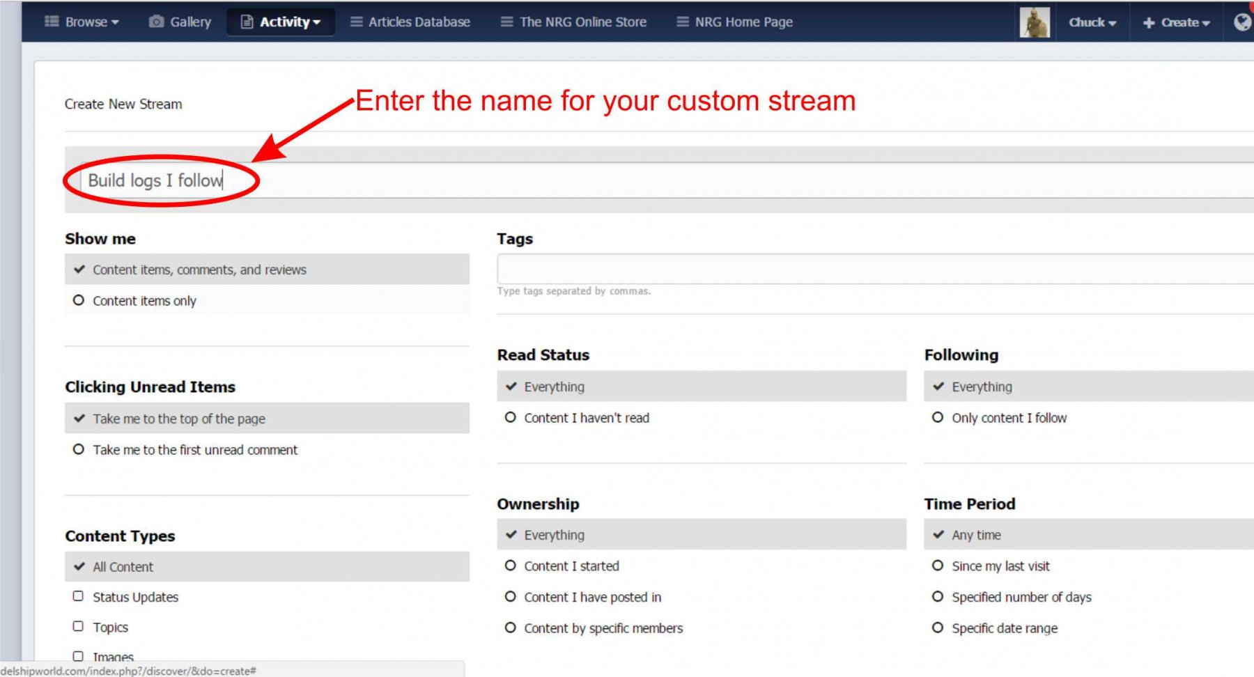
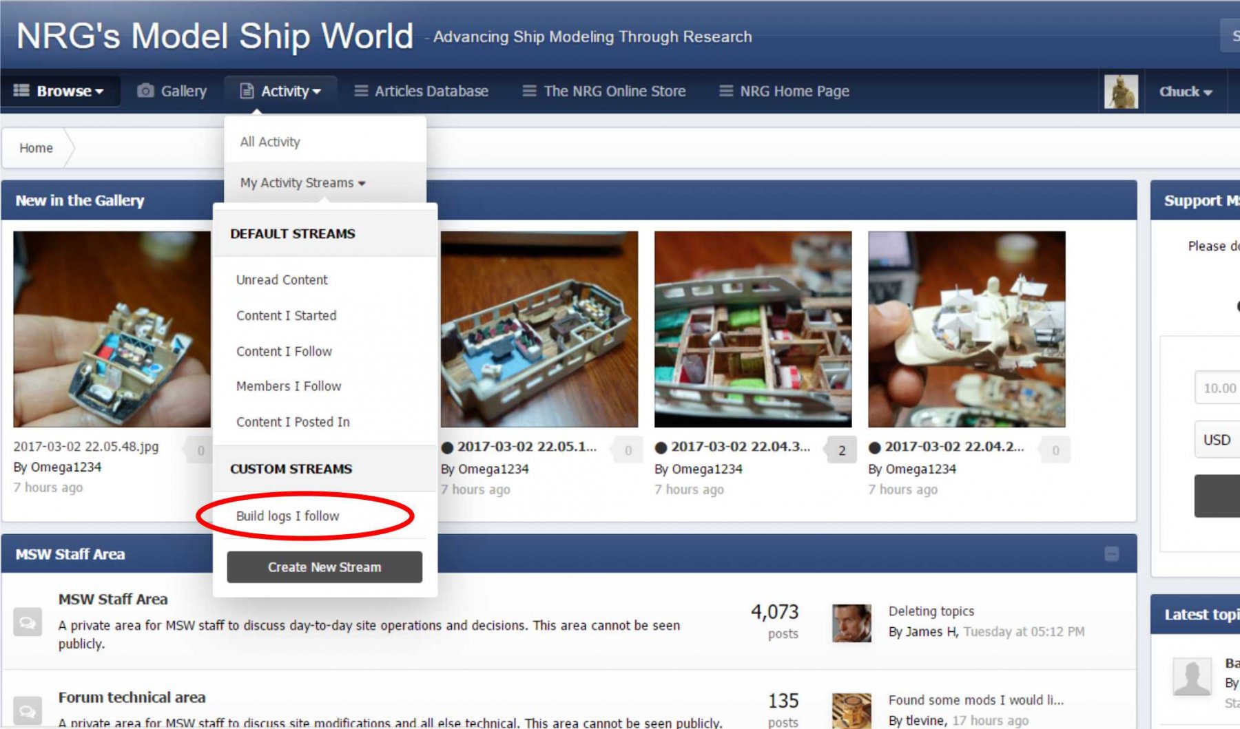
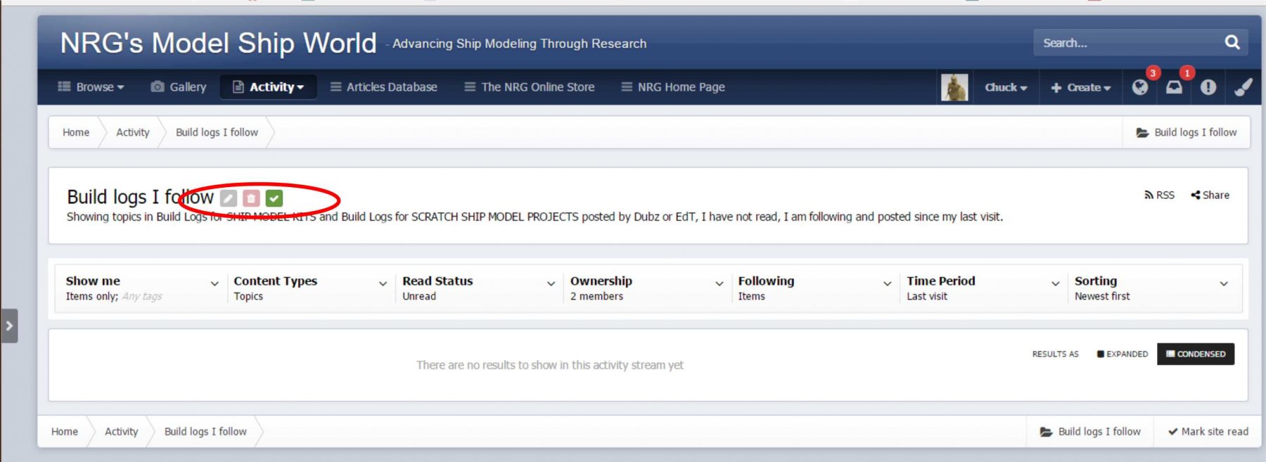
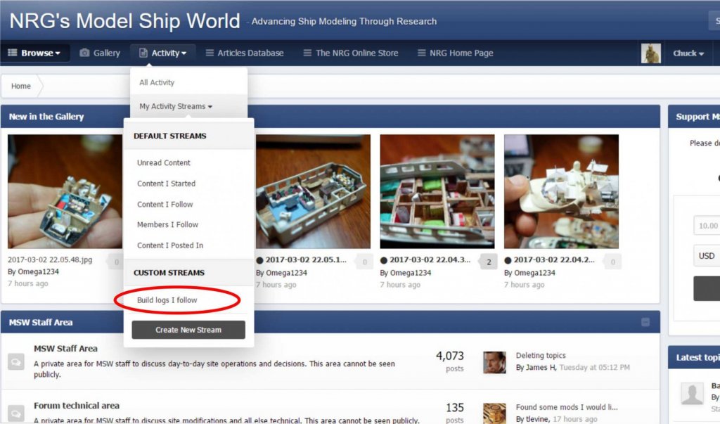
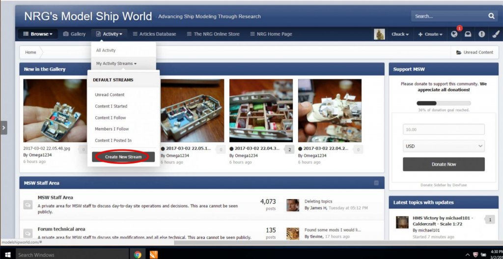
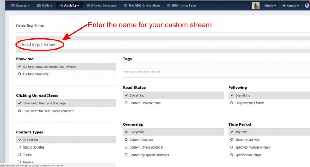
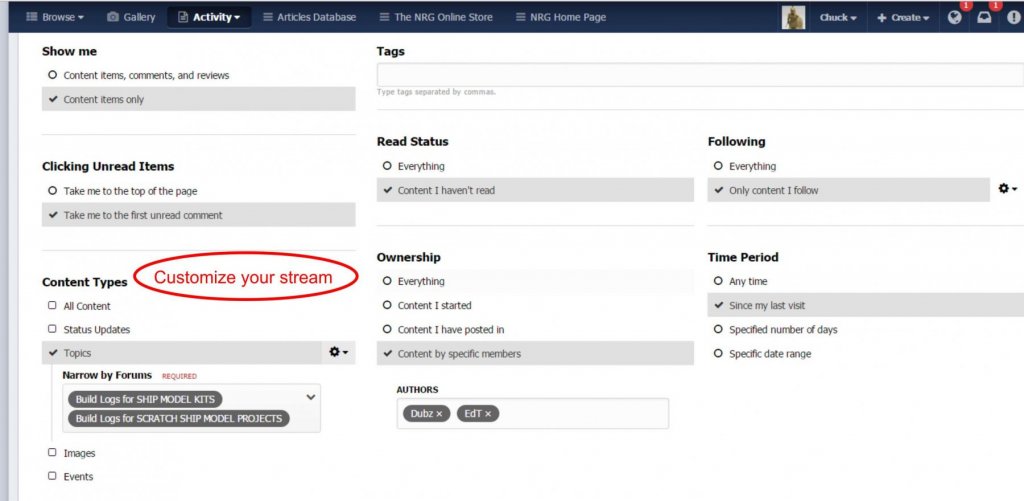
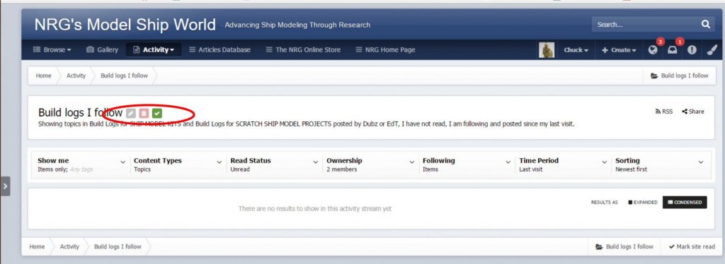
What is an activity stream? It is a fancy word for the custom search of the content on this site, which at the click of a link you can view precisely what you want. Currently there are only the default streams set up. You can view these by hovering over "Activity" in the menu as shown below. Note the "MY ACTIVITY STREAMS" Click on "MY ACTIVITY STREAMS" and you will see the default streams. They are pretty good but I know you will want a more targeted stream of content you are interested in. For example you can set up a custom stream that will show you only unread activity in build logs for three people you specifically want to check out regularly. And you can filter other restrictions. Just click on "Create new Stream as circled below. You will get to a filter screen where you can name your new customized search....see below Then select the other customized features you want. Below you can see I selected individual forums and even made it specific to just two members.....and content that I havent read since my last visit. You can set it up any way you want.... After you save your customized stream (lower right is saved button) it will now appear in the drop down as shown below....this is the test stream I just set up..... If you click on it....it will show you only what you asked it to show you. See below for my custom activity stream. There is no content because I made it very narrow with only two members as you see. Read the description of my custom stream below the red circle. Also note that the icons in the red circle let you select this as your default stream or you can edit it or delete it. It will remember your selections and now all you have to do is click on it whenever you want to see this particular stuff. Even more awesome is that you can set up as many custom activity streams that you want.........

- 21 replies
-
- 16
-
-
There are a half dozen ways to do this actually. But first you must be willing to try some of them. Play around a bit. For example. What Chuck mentioned is a great way. You customize a "stream" It can show you a list of only what you want to see. Every time you click on it. And you can set it as the default stream to make it easier to access if its the only one you use all the time. -go to the activity drop down -click on "my Activity Streams" -at the bottom you will see "create new stream" -here you can call a new stream...."unread build logs I follow" -then just set up the filters including what forums like "build logs for kits" or both kit and scratch logs. Then filter so it only shows the logs you follow and unread content since you last visited. Or whatever other criteria you prefer. Its really a wonderful feature -It will show you only what you want to see every time you click on that activity stream. AND you can make it the default. Then you can just click My activity streams and it will show you only what you set up. -AND you can create as many personalized streams as you want. Think of the word "stream" as a fancy word for "automated search based on your own criteria" OR....you could get grumpy that stuff has changed. But the new "activity streams function" gives you the opportunity to personalize any search for content whenever you want it and with the exact criteria you are looking for. Its a thing of beauty. And yes a new FEATURE thanks to the upgrade. I will make a new topic with this info.
-
Just use the follow feature or ignore features. Its new and yes its different. But its not difficult for most.
-
The stuff is back......scale hardware was bought out by model motorcars https://model-motorcars.myshopify.com/collections/small-parts-hardware/bolts Greg you can take a deep breath now!!!!
-
There is a preview.....In the editor as you are typing your post.......the very last icon. The one that looks like a piece of paper with a magnifying glass. In fact, just hover over every icon in the editor bar to see what you can do. Chuck
-
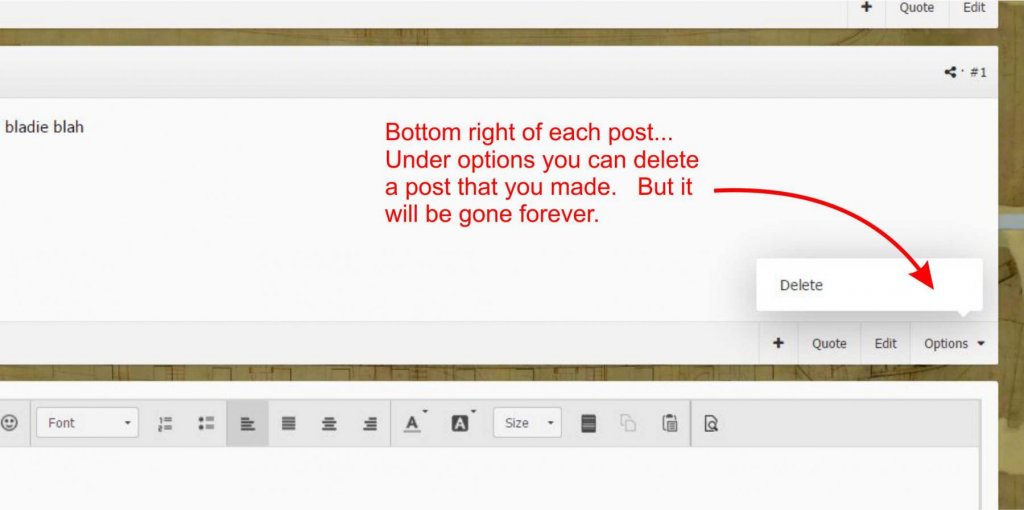
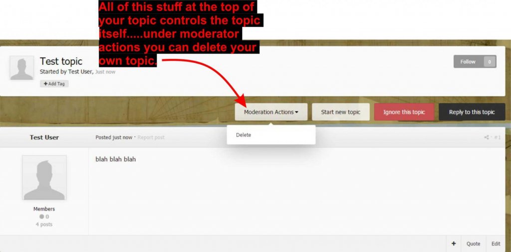
Yes indeed......trust me we now understand.......... OK....to delete a post you made (NOT A TOPIC). click the options dropdown on the lower right of your post. You will see delete......it will NOT be gone forever. It goes to a holding bin for one month and then it goes away forever. It will ask you if you are really really sure...... Most important...when you want to delete a WHOLE TOPIC you started. See the four buttons above each topic .....at the top of your topic, these control your whole topic and NOT just a post. You can ignore a topic etc. But if you select Moderation Actions, you will see "delete, be very careful". This will delete your entire topic, including anyone elses posts that were made in it. You will see a pop up that ask you if you are really really sure about this.... If even after all of that, you deleted it by mistake, the topic can be restored within a short period of time if you contact an admin. Be sure to tell them the name of the topic and what forum area it was originally in so they can put it back there. But after one month if you dont contact us it will be gone forever.
-
Will do......and give me a moment to do some screen shots and show everyone what is what. Remember......delete a topic and we can save it if you let us know soon. Delete any individual post and its gone forever. Back in a few minutes with some screen shots. Chuck
-
OK....as you guys know, we turned off the ability for members that allowed you to delete your own content. We did this because two or three members deleted their build logs by accident. They were not recoverable. However, by turning off this feature, it also disabled a members ability to delete the last post they made if they made it in error. Whether on their topic or someone elses. These two features are not separate in the software. So to be clear, either you can delete both topics and the last post you made or nothing at all. I understand how this can be a pain in the butt. If you post something and want to delete it, you cant right now. You can only edit your last post and remove the content. Leaving a blank post. Then you would have to contact a moderator or staff member to have us delete it. Or we would have many posts that are blank or that you write..."removed content". This is not ideal and quite sloppy Why am I repeating all of this here? We may have a solution. We have mitigated this somewhat. We have created up a feature currently only available to mods and admin. When we delete a whole topic, it doesnt actually get deleted any longer. It will be moved to a new "trash can" topic hidden from view. Only a moderator or and admin can delete topics that end up in this trash can. Until we do delete it forever it can always be moved back to the forum it came from. I guess you can call it a restore feature. BUT...this feature only applies to complete topics. NOT individual posts. So when a post (like one you had second thoughts about making on a topic is deleted) it will be gone forever. This also applies to us mods and admin. When we delete an individual post....its gone forever. SO.....what I am saying is.....we can now turn the feature back on that will allow you delete your own topics that you started and posts you have made. But remember....individual posts are gone forever. Only complete topics are sent to this "recoverable trash can" Should I turn this feature on for members????? Pros. You wont have to worry about deleting a complete topic or your build log and it will be gone forever...... you wont have to bombard the staff with requests to delete topics or individual posts....which judging from past activity happens very often. When you dont tell us to remove a post you made in error we will have useless posts emptied by each member hanging out on the site. This prevents that. Cons.....if you do mistakenly delete one of your topics, you must recognize soon that you did delete it by accident and tell a staff member to restore it.....we wont leave topics in this trash can forever. We will empty it from time to time. So you cant ask us 2 months later to restore a topic. Once again......posts are gone forever....but a staff member will be able to restore your accidentally deleted topic. Do you guys feel comfortable with this. If so I can turn it back on for a trial run. And I will post some screen shots of where you can go on a post to delete it vs. deleting a full topic. But I fear even with instructions some of you will mistakenly delete something..... and once again....posts are gone for good. BUt a complete topic you delete will now be restorable. this is something we set up as a direct fix after several members mistakenly deleting their build logs with no easy way to recover them. Now they will be recoverable.