
Chuck
-
Posts
9,096 -
Joined
-
Last visited
Reputation Activity
-

 Chuck got a reaction from Kevin in HM Cutter Cheerful 1806 by Chuck - FINISHED - 1:48 scale - kit prototype
Well that is very interesting. Thank you Sjors. I have printed it and will stick the printout in the model so when I am ready to restore her I at least have a starting point.
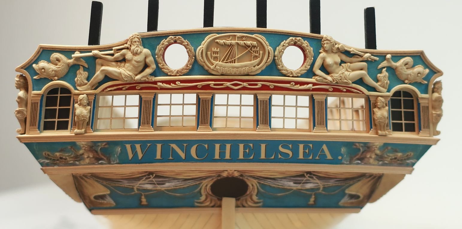
Here is the model in question by the way. I havent had time to give it a thorough researching yet. That is a big help. The name on the back is "Margareta" or "St. Margarethen"
Chuck
-
 Chuck reacted to figuerres in Fair American by figuerres - Model Shipways - 1:48
Siren 1:48 scale lantern kit with added LED light first try, I like how most of it came out.
-
 Chuck got a reaction from avsjerome2003 in 3D Printing - Not Just Yet!
I have seen better although they are slightly larger....1:24 scale. But they are crazy expensive and I dont know what machine he uses
-
 Chuck got a reaction from SawdustDave in HM Cutter Cheerful 1806 by Chuck - FINISHED - 1:48 scale - kit prototype
I was able to shape the fashion pieces today. They are will be in one piece with the boom crutch added separately later. The boom crutches wont be added until the cap rail is added way down the road. For now I just left them extra long so I can file them back to where I want them. You can see in the photo how the bottom fashion piece was bent using heat.....no water or soaking. The top one is the flat 1/16" thick piece which has not been bent yet.
Once these were glued on the model, the second layer of the wales (two strakes) were added and painted. I still have to paint them on the other side. After thats done I will treenail above the wales. That will be easier to do before I add the fancy molding along the sides of the hull per the plan.
Notice how the fashion piece covers the end grain of the planks on the stern transom. When the stern is all done there shouldnt be any end-grain exposed for any of the planking. The fashion piece and square tuck protect them from the elements.
-
 Chuck got a reaction from Jaxboat in HMS Winchelsea 1764 by Rustyj - 1/64 - POB - 32-Gun Frigate
Yupp....you are correct. There is one for every station line. Four times as many in a typical kit. It will make framing the gunports easier as well.
Chuck
-
Chuck reacted to Rustyj in HMS Winchelsea 1764 by Rustyj - 1/64 - POB - 32-Gun Frigate
Hello all,
Well I’m happy to say I’ve completed the planking on the portside too. No stealers or drop planks this
side either. All that is needed now is a good deal of sanding and then some wipe on poly. I have to say
planking this way is more time consuming but it works so much better and the run of the planks is much
easier to maintain. Definitely the way I will plank from here on out!
One thing I want to point out is that I handle a model a lot when I’m working on it.
Because of this I would inadvertently rub off some of the pencil marks. To make sure
I didn’t lose the main belt line mark I used a sharpie to mark them. Then if I accidently
rubbed off any markings I could go back to the main mark and redo them.
After I check the hull over and make sure it’s all set I will move on to the stern.
-
 Chuck got a reaction from Julie Mo in 18th Century Longboat by Nirvana - FINISHED - Model Shipways - 1:48
Nope....no good.....your piece is not oriented properly with the grain. That is why they break...rotate so the part of the stem that sticks up and always breaks is going along with the grain....rather than across it. This is super important and you should always keep teh grain direction in mind when posiitioning your templates.
-
Chuck reacted to Nirvana in 18th Century Longboat by Nirvana - FINISHED - Model Shipways - 1:48
A long time has elapsed since I started the log, however today I am uploading the very latest pics, work has been done during the day.
The hull was fully planked earlier this week.
I had to do some mod's as I noticed some of the planks didn't attach fully to the bulkheads. All is CA glued.
The bulkhead support (coffee stirrer from a famous coffee chain) was cut into parts by the new Dremel Micro 8050
The machine itself is really nice to work with, it's re-chargeable Li-On batteries charges fast and it's easy to hold (low weight)
General Finishes Arm-R-Seal is the poly wipe on I am using.
I didn't even bother to let it dry the slow way, I used the hair dryer.
Some extra light sanding I and I should be ready for painting.
-
 Chuck got a reaction from albertovecchi in HM Cutter Cheerful 1806 by Chuck - FINISHED - 1:48 scale - kit prototype
Thanks,
I used a hair dryer and slowly bent it to the desired shape while heating it up. The hair dryer was on the highest the hottest setting.
Chuck
-
 Chuck got a reaction from Archi in HM Cutter Cheerful 1806 by Chuck - FINISHED - 1:48 scale - kit prototype
I was able to shape the fashion pieces today. They are will be in one piece with the boom crutch added separately later. The boom crutches wont be added until the cap rail is added way down the road. For now I just left them extra long so I can file them back to where I want them. You can see in the photo how the bottom fashion piece was bent using heat.....no water or soaking. The top one is the flat 1/16" thick piece which has not been bent yet.
Once these were glued on the model, the second layer of the wales (two strakes) were added and painted. I still have to paint them on the other side. After thats done I will treenail above the wales. That will be easier to do before I add the fancy molding along the sides of the hull per the plan.
Notice how the fashion piece covers the end grain of the planks on the stern transom. When the stern is all done there shouldnt be any end-grain exposed for any of the planking. The fashion piece and square tuck protect them from the elements.
-
 Chuck got a reaction from aviaamator in HM Cutter Cheerful 1806 by Chuck - FINISHED - 1:48 scale - kit prototype
Got the counter and the transom planked. You may notice that I thinned down the outside stern frames considerably before planking the stern. The first photo shows how thick they were before it was planked. After the sides of the hull were planked the outside stern frames were strong enough to handle the thinning down. It makes the model more historically correct. The inboard side of the stern and counter will not be planked so I wanted to make sure it looked as authentic as possible. That of course means that I must really clean up the inboard side between the stern frames carefully to prepare it for painting. I will fill any cracks and sand it smooth and do lots of surface prep.
Now I can have some fun. Its time to put the fashion pieces on and the wales and fancy trim. This is the step that will make it really come together.
Chuck
-
 Chuck got a reaction from Nirvana in HM Cutter Cheerful 1806 by Chuck - FINISHED - 1:48 scale - kit prototype
The planking above the wales is basically completed. Just a few more planks to add on the port side as you can see. I didnt bother simulating the caulking between the seams where it wont show. So it looks a bit weird now. But once the molding and second layer of the wales is added it will look fine.
You can only see a few places with a crisp line for the seams. This was done by running a number two pencil down one plank edge. If I did this on both plank edges it would have been too pronounced for my tastes.
I will plank the transom and counter next at the stern. Its an interesting detail that in case of a cutter like this you dont plank the stern counter first. The transom and counter are planked after the sides of the hull. The exposed end-grain of the counter planking and transom planking will be protected from the elements and rot by the fashion pieces. You can see them in the profile drawing. So you will not see any of the end grain from the planking. The frame for the square tuck also does this for the end grain of the planks. Its an interesting feature and I almost forgot NOT to plank the counter first. It is something I am so accustomed to doing.
Before I plank the stern transom and counter I have some shaping of the outer stern frames to do. I will post pictures of this as well because its an important feature to keeping the finished model looking accurate. So far its coming together quite well without any real issues. Its a fun build so far. You can start to see the final shape of the cutter come to life as the planking progresses. I know the bulwarks look thick at this point but they will actually be thinned down quite a bit soon. The outboard and inboard planking at the sheer was actually just 1 1/2" thick....once its planked inboard and out the final width will be just 1/8 - 5/32" thick at the most. Closer to 1/8" thick I hope.
-
Chuck got a reaction from aviaamator in HM Cutter Cheerful 1806 by Chuck - FINISHED - 1:48 scale - kit prototype
Thanks guys
Rusty it will be basically the same. Except in this case the original planking expansion did show one drop plank at the bow. I am basically replicating that draft exactly. So I will include that drop plank and then divide the bottom of the hull into belts. But only two this time. Then I will line off the hull before moving forward with the planking.
Heres what the hull looks like after those two planks were added between the molding and the wales. I only darkened the seams where it will eventually be noticed. This helps if I need to tweak the placement of the second layer for the wales and molding. Without the seams darker its easier to move the second layer without folks noticing.
You will notice the darker wales. This was just a sheet of boxwood I had that was noticeable darker. I figured what the heck, I might as well use it for the wales. Its going to be painted anyway. It also helps me visualize the run of the wales as I plank above them.
-
Chuck got a reaction from Archi in HM Cutter Cheerful 1806 by Chuck - FINISHED - 1:48 scale - kit prototype
I started the planking today. This always begins with placing battens on the hull. The top of the batten represents the bottom edge of the wales. I really spent a lot of time on these because it will establish the run of all of the planks on the hull.
It was added to both sides so I can check it from every conceivable angle. Once I was satisfied I planked the wales with two strips. This will be the first layer. After I plank the hull from here up to the sheer, I will come back and add the final layer. Its a hold over from my time building kits. I like the idea of being able to make small adjustments with the run of the wales on the final layer. Since it will be painted black and this isnt the final layer it laid down in one long strip rather than in 25 foot long pieces.
Now on most ships you can just start planking from the wales up...the run of the wales determines the run of the planking above it to the sheer. Mostly anyway.
In this case however it isnt true. It is again one of the reasons I chose the Cheerful. Its not difficult work at all but requires careful planning. If you examine the plan for the cheerful you will see the run of two moldings just under and through the gunports. I was fortunate to have the original draft for teh planking expansion and my model will follow it exactly. The same number of strakes and their run are precisely copied from it. The space between this molding and the wales is not consistent. So I decided to add the 1/16" strip first which for the most part runs right under the ports, leaving a 1/64" rabbet along the bottom of each port.
Then I divided up that space between the molding strip and the wales equally so I can taper these two strakes that will fit between them. You may be able to see my tick marks defining the space and strakes on each bulkhead.
The molding strip is just the first layer also....Once its all done I will come back and add the final layer after scraping the fancy profile into it. Once again, having a little wiggle room to adjust teh run of the molding later is a huge plus.
Then its just a matter of finishing the planking and other molding strip as I work my way up to the sheer.
Chuck
-
Chuck got a reaction from Archi in HM Cutter Cheerful 1806 by Chuck - FINISHED - 1:48 scale - kit prototype
I managed to finish the skeleton for Cheerful today. So its now ready for planking. The stern framing was pretty standard although the design concept was modified for the square tuck. This is a feature that is rarely shown correctly on these cutters. There are some pretty complex angles. Its hard to tell in the images but the square tuck is not flat and completely perpendicular to the keel. It has a slight convex curve as it works its way from the center outward.
It isnt complete yet. The actual framed square tuck will be added after the sides of the hull are planked. Its probably the trickiest part on the model but I simplified it quite bit as far as the construction is concerned. But when its done it should look exactly like the real thing. Thats my hope anyway. The first image shows the Rogers collection model with its square tuck. The frame around the vertical planking will be added after the hull is completely planked. Then I will fill it in with the vertical planks.
Chuck
-
Chuck got a reaction from Archi in HM Cutter Cheerful 1806 by Chuck - FINISHED - 1:48 scale - kit prototype
Thank you. Its a tough thing to describe in writing. It is so much easier to demo it. That was a good idea about doing another demo at next years conference. I will talk it over with the guys. I actually did one for my local club members. I just showed them how to prepare the surface and paint a solid color without brush strokes. What brushes to use and how to paint a straight line without using tape.
When I was in college I had to take an entire course in color theory where we had to paint 2" x 2" square swatches of solid color. Th e teacher was rough to say the least. If the painted swatch wasnt completely flat without brush strokes and perfectly even color you would fail. I can only now see where that class had a purpose that was worthwhile so many years later. I had to paint hundreds and hundreds of swatches. Oh the memories of art school.
Anyway, after spending hours cleaning the shop, I had a chance to cut those forward ports. I used a scroll saw blade that I snipped a small length off off. I placed it in my hobby blade handle and used it to cut out the ports. You can see it in the photo. Then it was a matter of refining the sides of the port opening with files and chisels. This was to try and get straight sides and sharp corners.
Then I wanted to do a quick preliminary fairing inboard at the bow. I didnt want to look at that disgusting thick bow with all the laser char as I planked the hull. You can look at earlier pics to see just how thick it was. I used a sanding drum in my dremel to cut down the thickness to around 1/8" thick at the bow. It needs much more attention and will eventually be thinner. But its easier for me to look at now as I work on other areas.
Tomorrow I will start framing the stern permanently. Then its on to planking. You will see how rough and uneven the inboard side of the bulwarks look. I wasnt careful about how uneven the pieces of wood stuck out on that side. As long as they were deep enough to faired later I didnt care. I will take the sanding drum to it after the outboard planking is done and it wont take long to make it all look nice and clean. You can start to see that taking shape at the bow after just the preliminary thin-down. The stern frames are still just taped into place temporarily. You can see how they are let into slots in the two last bulkheads. It makes proper placement a lot easier.
-
Chuck got a reaction from Archi in HM Cutter Cheerful 1806 by Chuck - FINISHED - 1:48 scale - kit prototype
Thanks Guys....
Tom, I will bring her to the meeting tonight along with the plans to show our Jersey Club Members. Its bring a model night!!!!
I finished framing the port openings in Boxwood. I used the reference line from the batten to mark to top of the gunport sills. They should paint nicely because they are all boxwood. Unlike the first port which will be cut from ply fillers. You can see it marked in pencil. I am about to cut it out right now. I also laser cut and tested the stern frames. They are not glued in yet. Its just a test and all looks good. It helps make the shape of this little cutter come to life. I will begin permanently framing the stern as soon as I cut those two forward ports. Before painting them I will prepare the surface with wood filler or even gesso to smooth it out. This creates a nice surface to paint on after its sanded with a very fine sandpaper.
-
Chuck got a reaction from Archi in HM Cutter Cheerful 1806 by Chuck - FINISHED - 1:48 scale - kit prototype
Today I wanted to get the crappy part out of the way. What a mess. Fairing the outside of the hull before I start putting in the port sills.
Lots of saw dust. You folks are very familiar with this. Even with a smaller hull it took the whole day. This is the single most important part of the project. Unfortunately because its such a pain its easy to understand why people rush through it only to have issues later on.
At the bow is the usual "Bow filler piece" and a few horizontal pieces which is where the forward port will reside. Fairing the bow was challenging. Whenever you think its done...its really not. This is easy to spot using a batten. I dont angle my rabbet for the planking until this stage. And its important. Most folks angle the rabbet before gluing the bulkheads into the former. But I can never get the angles right. Its easier for me to visualize when fairing the bow and inserting battens every now and again to see how they fit.
Before fairing
After a good start at fairing the bow. Notice how the bulkhead former within the rabbet is faired to match the angle of the bow filler after its faired. If you dont do this then the plank wont fit nicely into the rabbet and defeats the purpose of having one to begin with. This is what takes lots of time. Small chisels nd sanding sticks...the usual suspects to do it. I am using the laser char on the bulkhead edges to check how the fairing is progressing as I work towards mid ship. Then I switch around and work from the stern to midship again to complete the fairing.
Here are some battens added to check the run of the port sills. There are laser reference marks on each bulkhead as is usually the case. After some careful adjustments the top of the batten was marked off on each bulkhead edge to indicate the top of the port sills. Notice how the batten fits into the rabbet and because of how its faired, I didnt have to even pre bend this strip. It lays in there perfectly and no pins are used to hold it in the rabbet. That will make planking so much easier.....which would have been a fight if I didnt take my time with this fairing. I am gald its all done, but I can still see some spots...
Tomorrow I will add the port sills and port framing before starting on the stern framing.
-
Chuck got a reaction from Archi in HM Cutter Cheerful 1806 by Chuck - FINISHED - 1:48 scale - kit prototype
Seeing as I have to make another windlass anyway...I will alter the plans to show the bar holes on every other face. Its an easy fix. I can see that it would make sense...or to alternate their position should they appear on every face like shown on John;'s example he posted above. Dont y0u wish making changes in real life was as easy as having Photoshop.
Heres what she looks like with every other...piece of cake...
-
 Chuck got a reaction from PeteB in HM Cutter Cheerful 1806 by Chuck - FINISHED - 1:48 scale - kit prototype
Thanks...
The shop will hopefully be cleaned after I get back from St Louis.
Alistair, I wont be distributing the DXF files. That would just make it to easy for folks to duplicate everything and pirate the plans. The plans will be sold in paper format only, rolled and mailed in a tube. As far as the laser cut parts go...I really want this to be a scratch project for folks and I dont see myself getting in the kit business. As we were talking about earlier...Maybe the bulkheads but thats it think. But who knows, we shall see, I hate to close the door on it all together.
I am however using the laser for most pieces of the prototype. Its quicker and I consider it just another tool like a scroll saw. Plus, after what I paid for the laser, I might as well use it whenever I can. Having said that, these pieces are easy enough to cut with a scroll saw. Its a really basic design and a simple single masted cutter. Its the perfect starter project for a first time scratch builder. I have tried to keep it as accurate as possible and as you will see with the square tuck at the stern, its the first POB cutter project that will show it correctly modeled.
So basically...the plans and a few other laser cut pieces will be made available but not a full kit. No electronic files either. Other than the monograph which will be free. I think folks will enjoy building it. I hope.
The treenails on the stem and keel are all done. Tomorrow I will glue in the bulkheads and start on the gunport framing and bow fillers.
-
Chuck got a reaction from PeteB in HM Cutter Cheerful 1806 by Chuck - FINISHED - 1:48 scale - kit prototype
Thank you...yes I am very lucky and fortunate to have a large shop...I dont know how I could work down there for so long if it wasnt as large.
Anyway..
I actually started gluing up the bulkhead former. It was in two pieces as you saw earlier. Then I added the rabbet strip which was 1/8" x 1/16" in size. It went all along the bottom of the bulkhead former and up the stern post. Because the former was 1/4" thick this left a nice rabbet when everything was all together. I tapered the bulkhead former at the stern from the bearding line to the rabbet strip. I used a combination of chisels and sand paper.
Once completed, I cut the pieces that would make up the stem. I decided to just use boxwood. To keep it in the proper thickness the thickness for the keel and stem needed to be 7/32". I could have just used a 1/4" thick piece because after sanding it would eventually be the right size. But I started with a 7/32" sheet. The pieces were glued together and pencil was used to make the seams show up better. It does a nice job of simulating the tar par and caulking and such.
You can see that I added all of the pieces except for the stern post. I like to leave this off until the hull is planked as I did with my other builds. I did cut them all out though. These are the only pieces including the rudder that will be this thick so I went ahead and cut them all. I will set them aside for later.
You will also notice the five holes in the stem for the deadeye halliard. This is for the main stay. I added the grooves above each hole at the appropriate angle so the halliard will lay correctly when rigged. I still have to add the treenails through the keel and stem pieces. Maybe later this evening.
-
 Chuck got a reaction from mtbediz in HM Cutter Cheerful 1806 by Chuck - FINISHED - 1:48 scale - kit prototype
And just to round out the images of where I spend 10 - 12 hours per day...
This is the other side of the shop which is in my basement...yes I know it is an absolute bloody mess. In total its about 25 feet long and 18 feet wide with that little hallway which leads to my kids man cave.
This is my block making station where yesterday I finished up milling 2000 2mm blocks. Theres a lot of sawdust on the floor....and my shop mascot snuck in the picture. You can see a drill press behind my hi-tech dust control system...the fan. , Byrnes saw and Sherline mill.
This is one half of my rope making station...You can see one half of that cheapo ME ropewalk on the table as well as all of the scraps from making a few thousand feet of rope over the last few days....I WANT TO BELIEVE.
I will be bringing all of that rope making stuff to St Louis to do a demo for the NRg Conference. I will be showuing how I make 20 - 23 foot lengths of rope on that little Model Shipways rope walk....thats how I make all of it.
And then looking down the length of my basement and down the 30 foot long hallway to the other end of the rope making station. This is where I make my rope. Nothing too terribly exciting. Alond the wall is my library and a bunch of old models...including the 18th century model that I should really find a better place for. There is another old Dutch model there too that is crying out for some love and restoration. I have no idea what it is but looks about 60 - 70 years old. Maybe. By God I have to tidy up this place...there is crap all over. I am embarrassed.
-
 Chuck got a reaction from Erebus and Terror in HM Cutter Cheerful 1806 by Chuck - FINISHED - 1:48 scale - kit prototype
Well I dont have any pics of the machine working...today is a rope making day. But here are some images of the shop with the laser cutter. Its very very messy as I am in high gear making stuff for the NRg conference in a few weeks. The laser cutter....is a BOSS Laser cutter 80 watt. But its custom and I had the larger laser tube placed in a smaller machine body for space reasons. I dont need a huge laser bed because most of the parts we make are small. I am very happy with its performance. Buying a laser cutter is like buying a car...so many opinions and stuff to weed through on the web about which is the best one. This particular unit cost about $5500 after everything was all set up. The cheaper desktop models you see just wont do the job and cut very poorly. Many promise to cut through 1/4' plywood but just wont. So far I was able to cut through teh plywood using only 65% of the power that this tube is capable of generating. It sits on a stand with wheels and can be rolled around teh shop but I like it right next to the workbench. Its just like sending a document to the printer....instead you just hit "file Cut" rather than "file print". Its very easy to get up and running.
Baiscally the Laser is hooked up directly to an old laptop of mine. I use Corel Draw to draft my cutting files. They are saved as DFX files and opened up in the laser cutters software...lasercut 5.3. Note the dryer exhaust behind the laser cutter. The laser cutter doesnt leave behind anything after it cuts. It actually obliterates the wood in its path leaving only residue....thats the brown stuff you see on the cut edges. It is also on the laser bed. It must be cleaned from time to time. The material will smoke a bit as it cuts and there is a powerful exhaust fan that blows it outside through that vent. My shop always smells like a fireplace now...very pleasant actually. But I wont cut plastics and other materials because its noxious and the fumes are usually very hazardous...it could literally kill you.
Its a bit noisy because of the blower to work the exhaust and the pump to cool the laser tube. Water is constantly pumped through the center of the laser tube as it cuts.
You can see its size in relation to my work table...
This is the bed of the laser which allows me to cut a 14" x 14' piece of wood comfortable. Its big enough for what we do.
This is the actual 80 watt laser tube in the back of the machine....the heart of the machine. Th e laser beam is invisible and bounces off a series of mirrors to the laser head. The laser head moves with a pulley and track system to follow the path of your lines.
The three things used to become an effective laser cutter is mastering the POWER setting for any given thickness of material, the SPEED of the laser as it travels...and the maintenance of the machine to focus the laser as sharply as possible to give you the thinnest kerf. Oh and of course the drafting and files you create must be done to the best advantage for your laser settings.
Basically its trial and error...place a thickness of wood on the bed and try various setting of power and speed until you find the optimum settings. Every type of wood and thickness has different settings and they are recorded once I find them.
Now back to the rope burning station where I need to finish up these 24 packs of black .012 rigging rope. From high tech to incredibly low tech in just a few steps.
When you think about how much money you could spend on a Sherline lathe and mill and all of the accessories...$5500 is not that crazy. I make a lot of parts for a living and that isnt the case with most ship modelers but I view this as just another tool to make parts. You can excel at using it just like you could with a mill and lathe...which by the way, a lathe is something I dont own.
-
 Chuck got a reaction from FrankWouts in HM Cutter Cheerful 1806 by Chuck - FINISHED - 1:48 scale - kit prototype
I have already received the gunnades (carronades on carriages) for this model. Thought I would share some photos. These are turned brass just like the cannon I carry.
These are actually all ready to go...along with the carriages which are also already laser cut. I am getting there...havent built one yet though.
Chuck
-
Chuck got a reaction from FrankWouts in HM Cutter Cheerful 1806 by Chuck - FINISHED - 1:48 scale - kit prototype
Today I laser cut the bulkheads and false keel from 1/4' thick ply. It was comforting that the laser cutter will have no problem cutting through this thickness of ply. That is really good. Normally you will see 3/16" thick bulkheads. I have started to use the thicker stuff in my latest designs. I think it really helps with the stability and strength of the hull. Its just a better thickness to go with in my opinion if you choose POB. When you no longer have to worry about mass production and kit MFG profit vs. loss, you are free to do these things. Its a great feeling and in the end make the modeling experience so much better.
The parts fit really well. You can see how large in comparison to the Winnie in the background. I made the bulkhead former in two pieces as you can see. I think its important to make these in shorter lengths. If they are too long they have a tendency to warp and bend. The slots cut for the bulkheads makes this even more of a problem. It helps the warping become even worse. You will also notice the many, many bulkheads. I have added a picture of the Sherbourne cutter by Caldercraft for comparison of design. With bulkheads that far apart the planking is going to be tough.
Chuck