HOLIDAY DONATION DRIVE - SUPPORT MSW - DO YOUR PART TO KEEP THIS GREAT FORUM GOING! (Only 75 donations so far out of 49,000 members - C'mon guys!)
×


michael mott
-
Posts
5,200 -
Joined
-
Last visited
Content Type
Profiles
Forums
Gallery
Events
Everything posted by michael mott
-
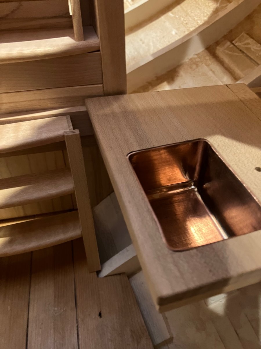
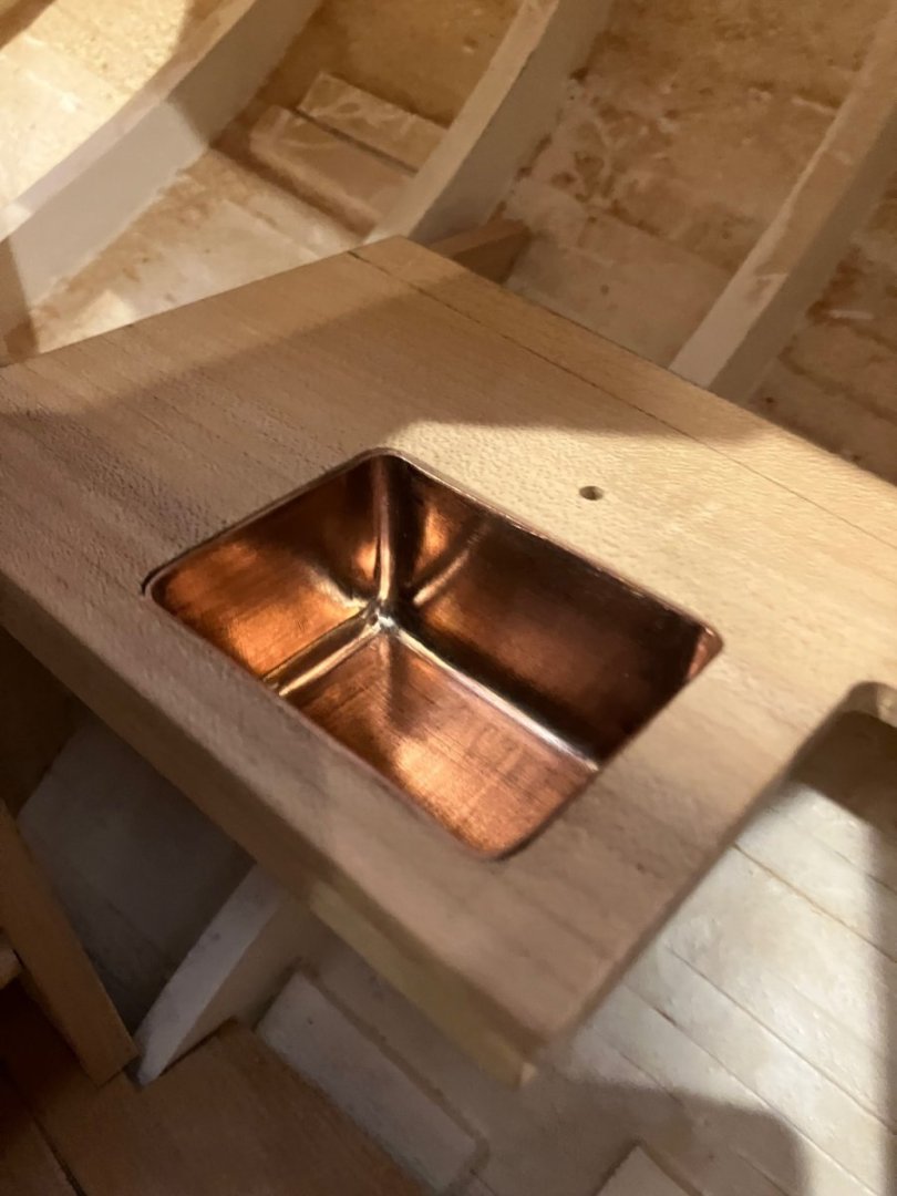
 The lip is now cut and rounded on the edges I will be raising the top when I get it back in the boat. Michael
-
Lovely work Richard also the cabinet in your earlier post. I am always on the lookout for salvageable wood for my model projects, it always breaks my heart to see an old house being crushed into matchsticks by huge machinery when much of the wood used could still be salvaged! The time is money myth will become apparent one day, but I digress. I am still using some of the eastern sugar maple that I acquired in 1973 as a six foot long green log after slabbing it up into quarters after taking a three inch plank from the centre for a coffee table and air drying the rest. It is what I am using for the interior of my Bristol pilot cutter. The deck is close grained salvaged old growth clear Douglas Fir. michael
-
Hi Rob just catching up with your work, nice mod on the bow. The water reminds me of my immigration journey from the UK back in September 1967 we were on the Cunard ship the Sylvania during a force 10 for three days in the North Atlantic. 40 foot waves. Michael
-
Keith , having spent the last hour and a half starting at the beginning, it looks like a marvelous project. I will most certainly be following along and gleaning tips from your ingenious problem solving skills. The comment about the breakfast counter made me laugh. It looks like you will have some fun with the bright-work and all those panels. Good to hear you are well, and getting stuck into the prep for the start of keel laying. Michael
-
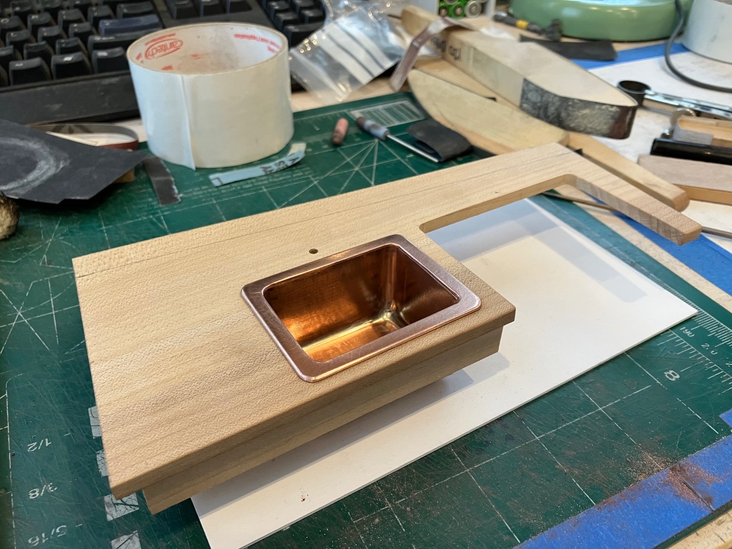
Just need to solder the top lip on and drill the hole for the drain the the sink should be ready, presently the countertop is at 28 1/2 inches I am wondering if it is a bit too low. Michael

-
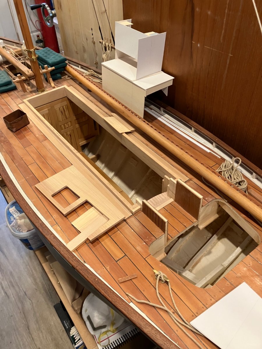
Hello everyone I’m just getting my mojo back in the ship modeling world. I had a heart attack in November 2022 and am now recovered from that. I had a wonderful conversation with David Anscherl earlier this week and he challenged me to do something on the cutter within the next 2 weeks. Yesterday I dug in and am happy to say that I am enjoying the work I am going to continue with the galley area which also includes the chart table on the starboard side The first task was trying to remember just what I was doing, then deciding what was the next step. The galley counter needed to be drilled for the tap and then the sink needed some serious work to clean up the sloppy silver soldering. So a few custom sanding sticks are being used to tidy up the sink. Time for some lunch Michael


-
Rob, Thanks for taking the time and energy to keep us all appraised of the ups and downs of this wonderful build. You have done to this layman at least an outstanding bit of research, and model-building in a way that has given me a much better appreciation for the shipbuilders art. A magnificent model of a beautiful ship. Congratulations. Michael
-
Hi Keith, Tricky stuff rigging, you are doing a superb job, like Eberhard said not exactly friendly to the folk who are challenged, but then there are all sorts of activities that require great dexterity and visual skills, which you appear to have in spades. Lovely work as always. michael
-
Lovely work Keith, I am surprised that the harnesses for the main sheet are just wire with no protection against chafing the wood boom. That wire would cut into the wood of the boom with the amount of pressure that the main would generate. Michael
-
Ken the ducket is for exactly the same purpose, the clearances and loading restrictions that were part of the early English railway standards are likely the reason for the small protuberance. Grant thanks for coming along for the ride. Mike, thanks. Learning and sharing of information it one of the joys I find that this site does so well with all the contributors and their various builds. Michael
-
Doing some catching up Keith, Wow what a superb job you are doing The rigging and sail making do look right I think that at the scale that you are working that "sewing" anything on the sails would detract from what looks like beautifully made sails. Our eyes put the "sewing there" because that's where the sewing is supposed to be! Wonderful work as ever. Michael
-
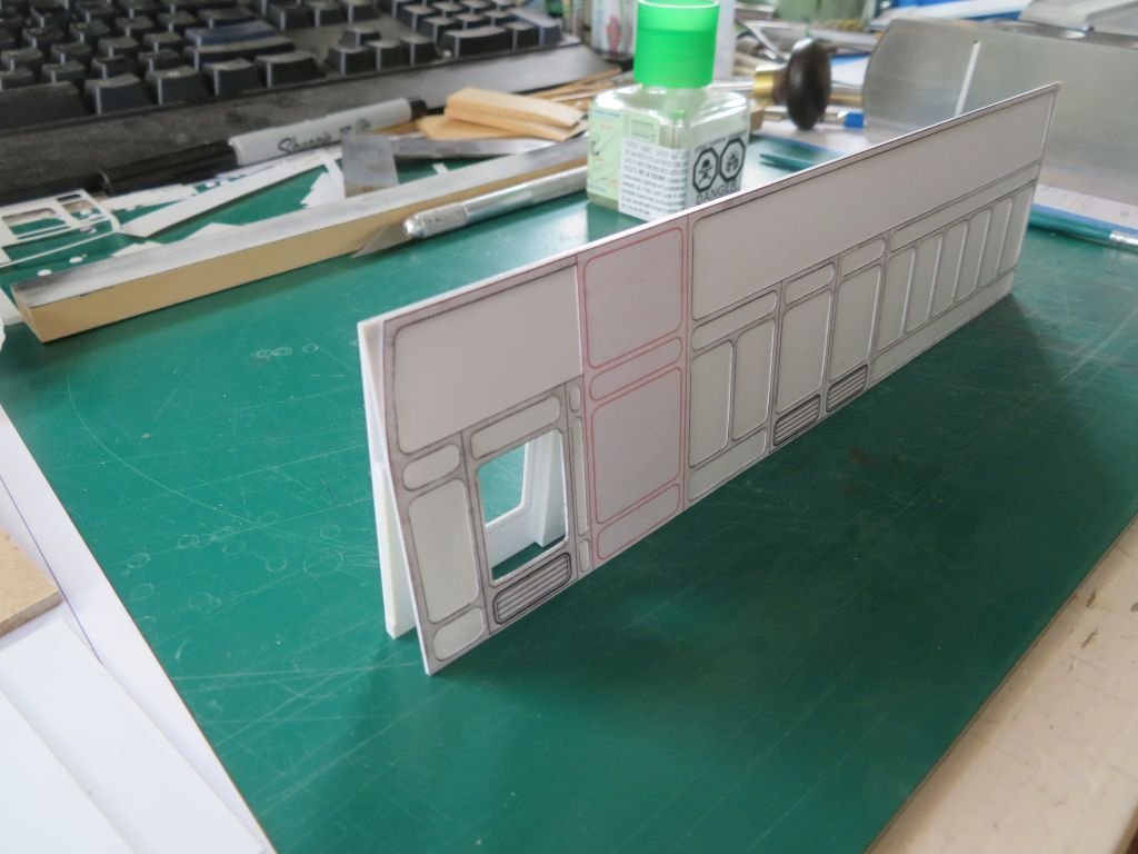
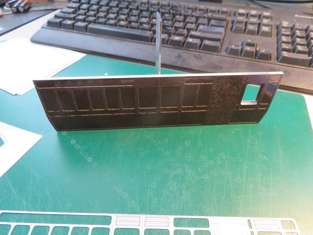
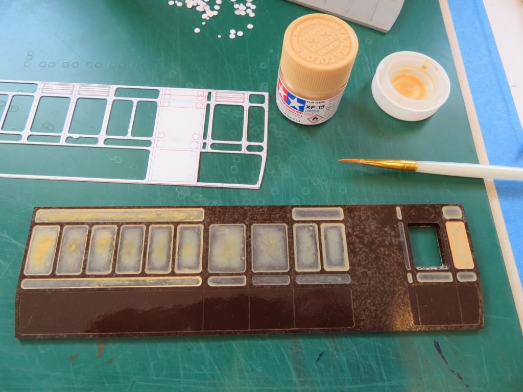
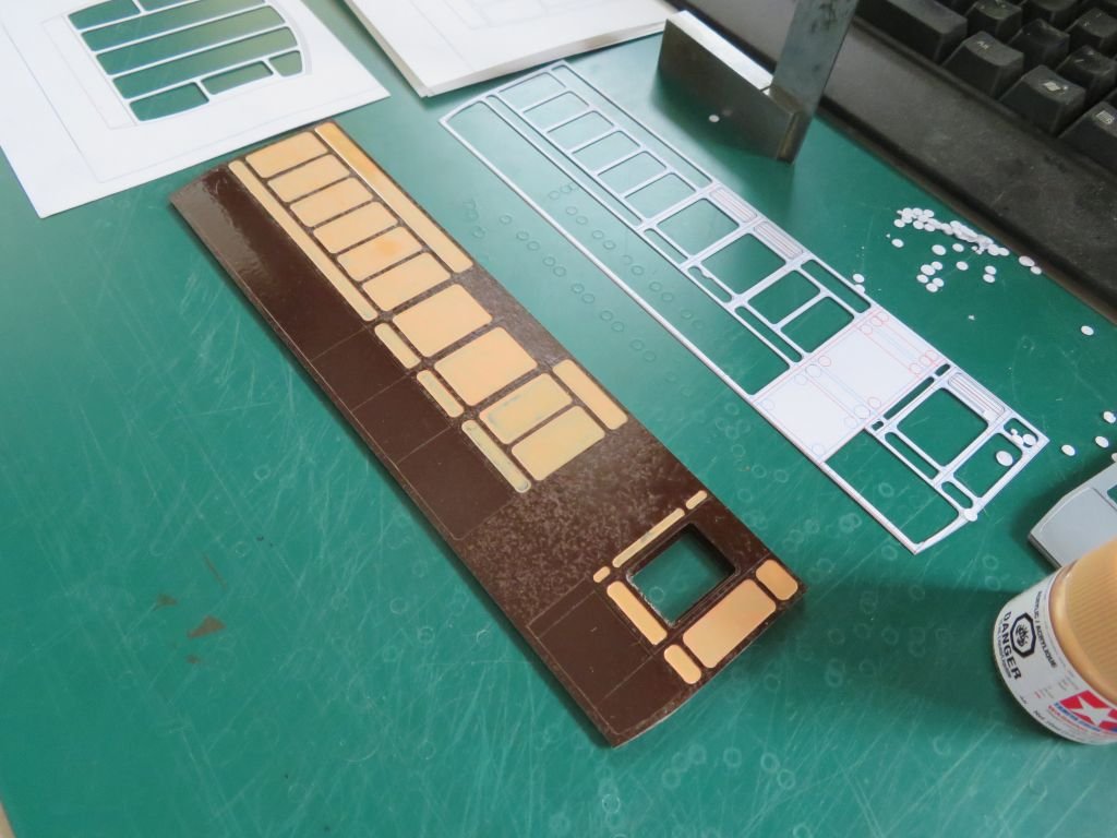
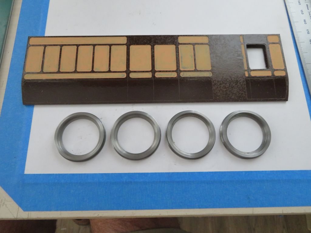
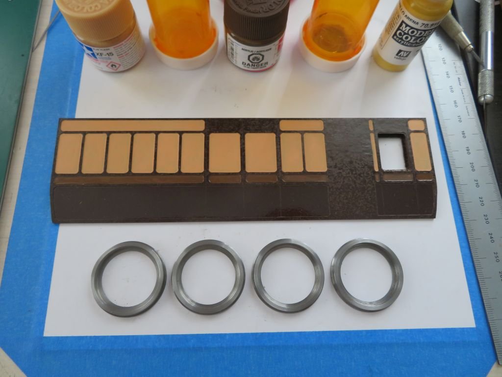
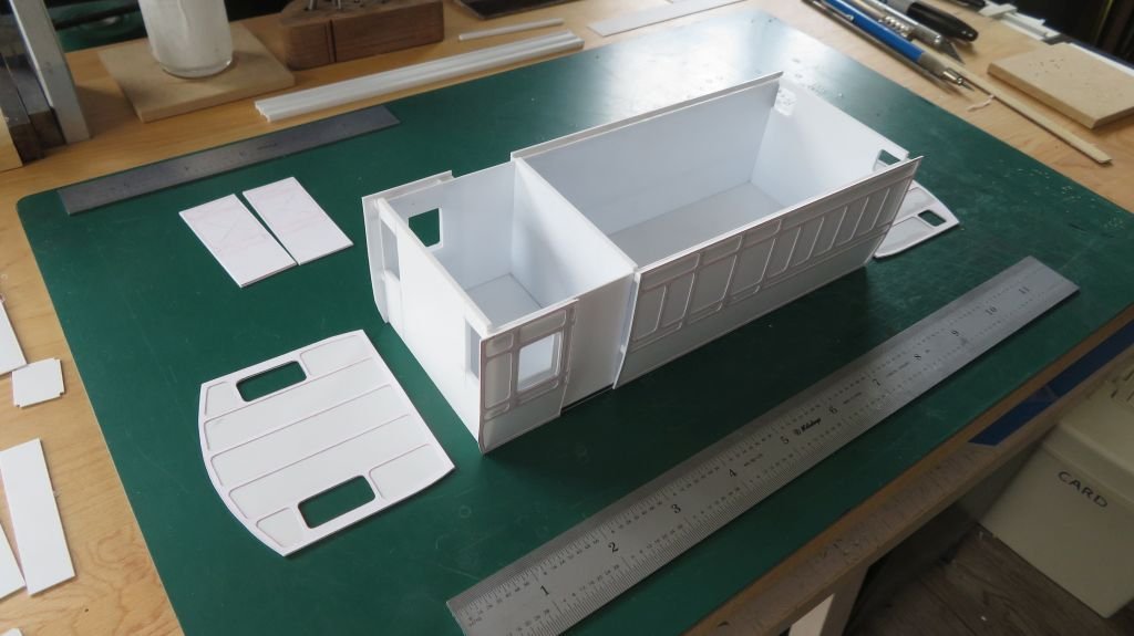
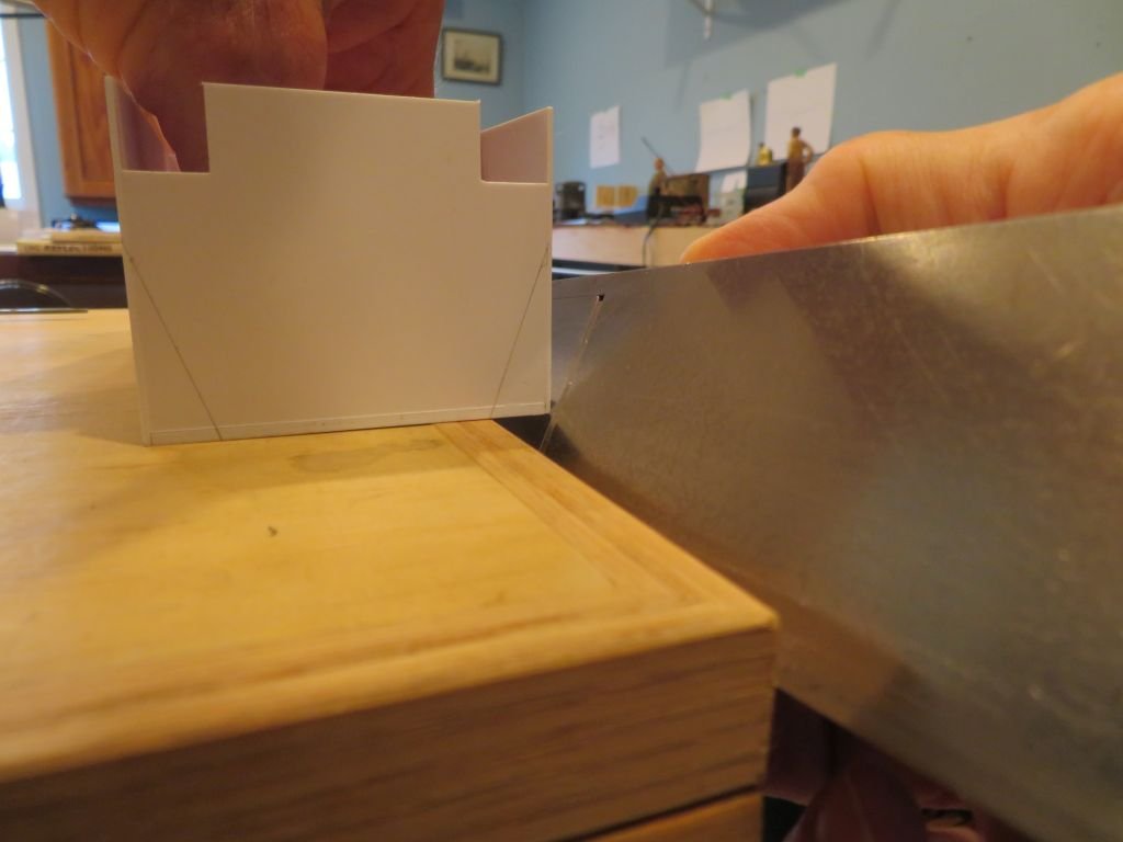
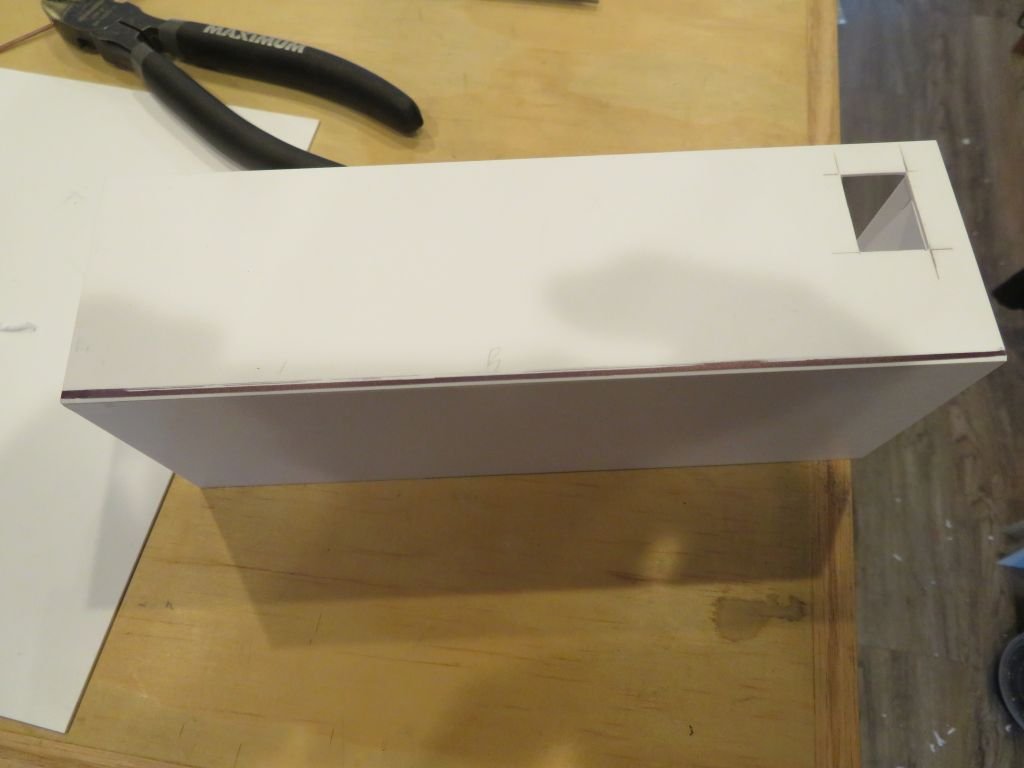
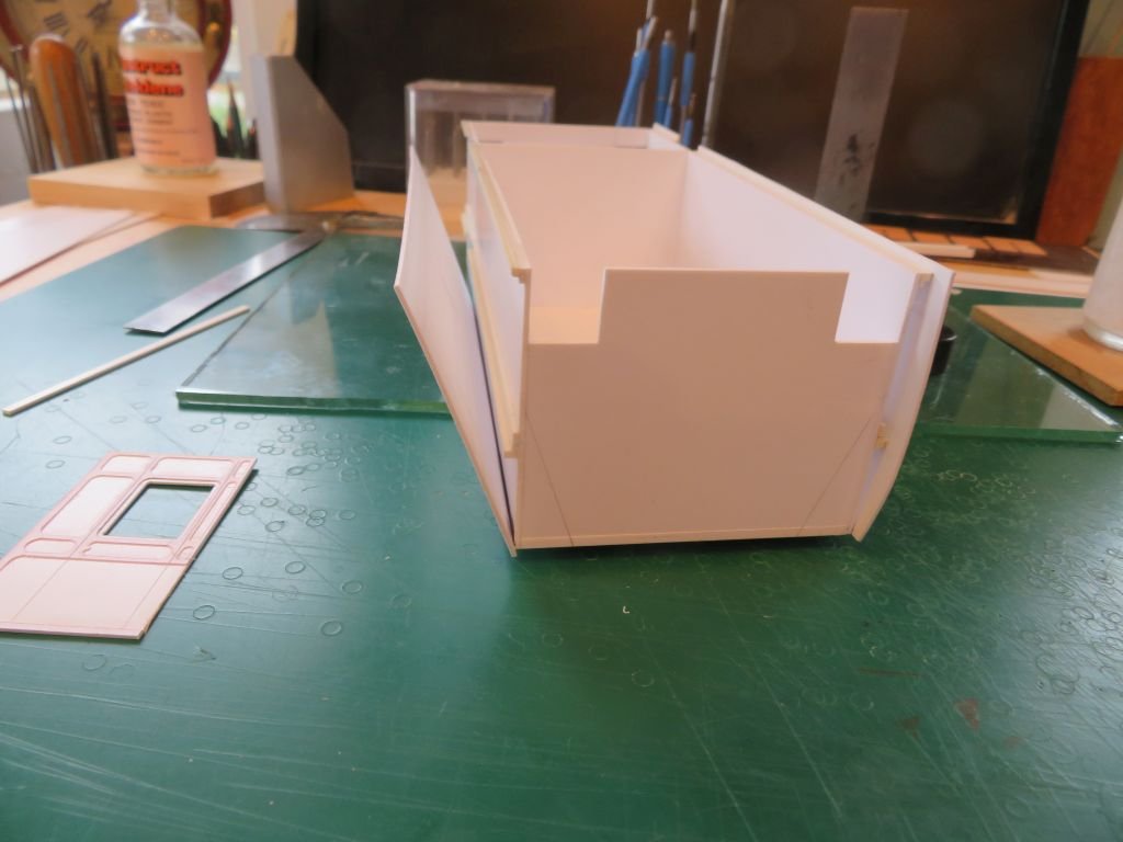
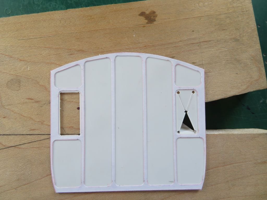
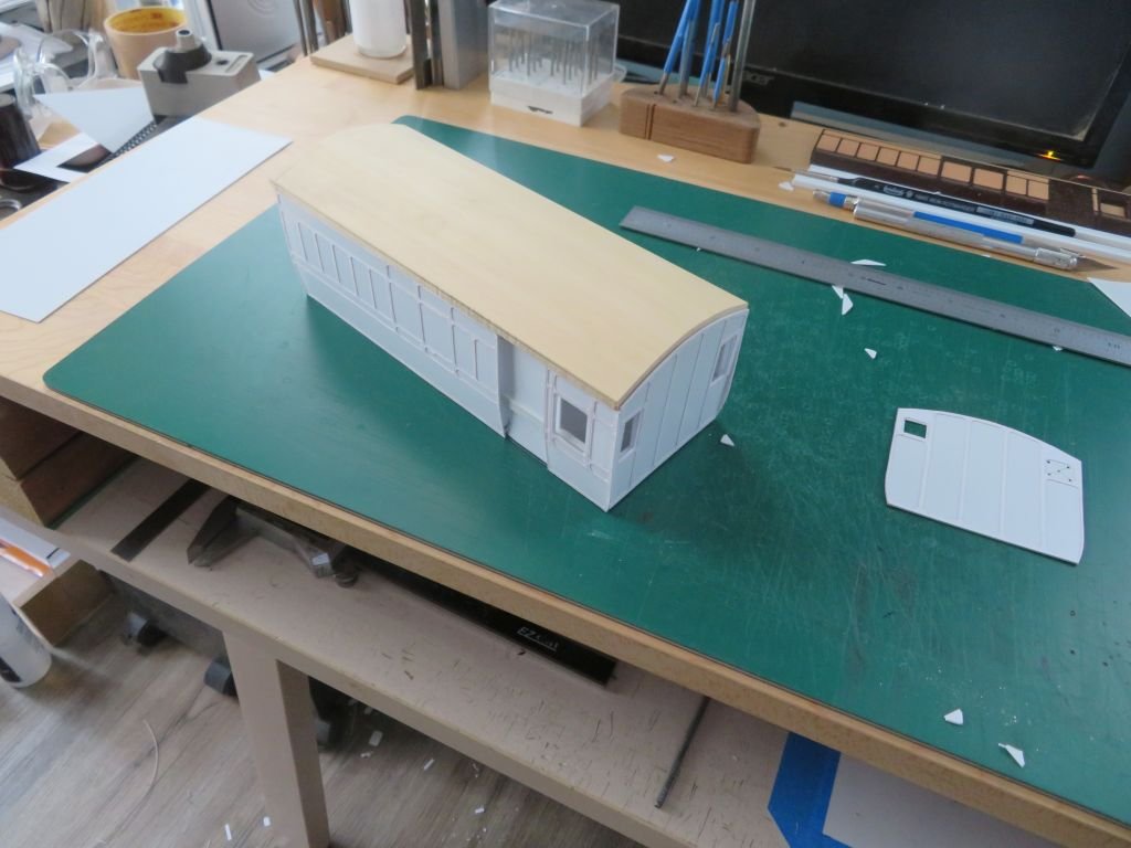
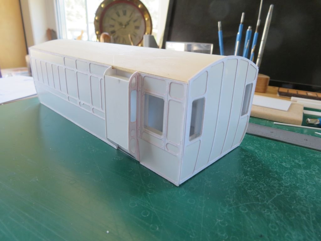
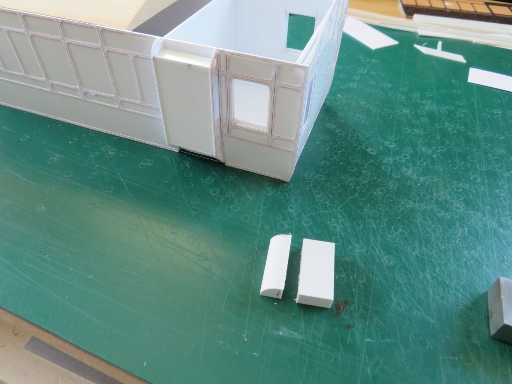
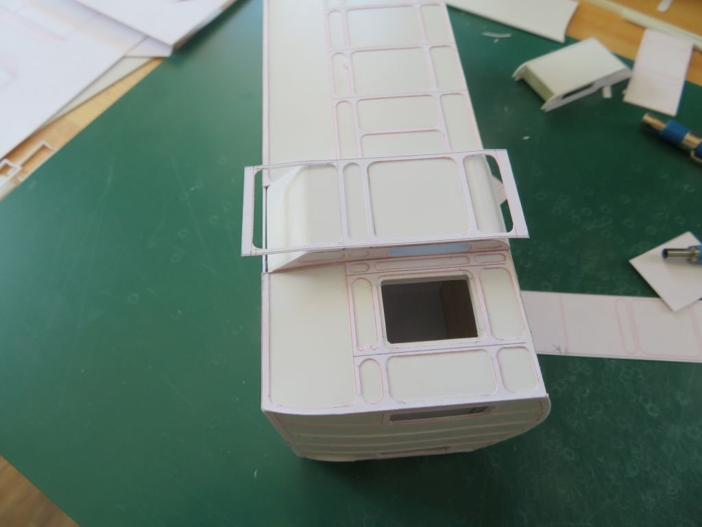
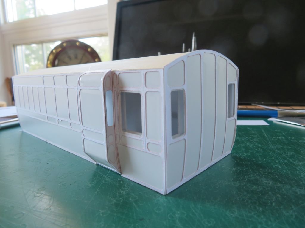
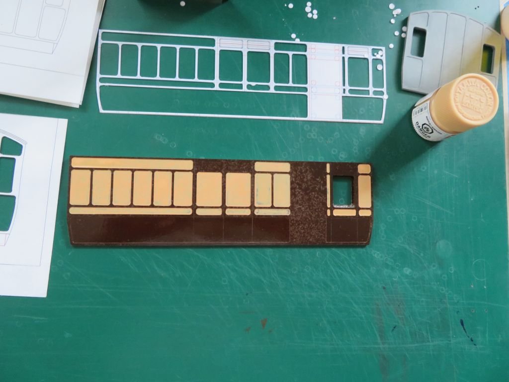
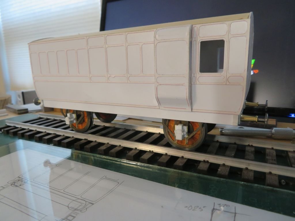
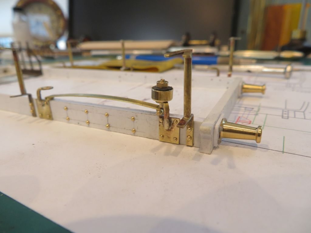
Starting over again somehow just as I was finishing I lost it all. Next the inner and outer side pieces ready to be laminated together, the upper portion is boxed with some 1/8th strips and the lower section clear to allow the outer layer to form the curved tumble-home. the inked line on the inner was a guide for the hand plane to for the bevel on the .040" inner wall. The bottom edges were glued with MEK and left overnight to cure fully. Once dry the test side panel was primed and painted with the brown colour, note the differing textures of the styrene and cardstock. I will ensure that when priming the actual model I will address this issue by giving the raised panel a light sanding to smooth the surface during the priming coats. The next task was to paint the inset areas with the cream colour and was advised by those who do a lot of coach painting to use very thin coats and to flood the panel areas and let the paint flow up to the border and not fiddle with it. this worked very well. after a couple of coats. And almost there. I took a break to let the paint harden up and started on the wheels which are a composite construction with steel tyres and wood between the tyre and the hub this is the standard Maunsell wheel which was designed to reduce the noise of the steel on the rails from being to loud in the coaches. I also noted that the painting was incorrect and did some remedial work to correct it. When starting the actual coach I followed David Jenkinson's method of building an inner box that the decorative panels would attach to. I transcribed the bevel of the sides to the end panels and this worked well when using the block plane. Then the outer panels were glued on , the top spacers were made horizontal to allow for glazing to be inserted from the ends before the end panels are permanently fixed after all the painting is complete. The end panels were made the same way as the first test pieces complete with their windows and tumble home and are able to be slipped in-between the side panels which are a little longer than the inner box. The roof substructure is made from a solid piece of yellow cedar and will be covered with and overlay of card and fine cloth to give the correct overhangs and texture. The edges of the roof substructure was slowly rebated to let it slip down inside the protruding side panels. The small protruding section called a ducket were made independently from the main body for the same reason as the ends and will be fixed after painting. The curves at the top and bottom were made from solid styrene and then the paper overlay was added afterwards. That's it for now. Michael
- 17 replies
-
- 19
-

-

-
Hi Andy thanks for the compliment. I actually to have one of those nibblers, and it is useful for some work but not this work. but thanks for the link anyway, I should probably get a new one as mine is a Bit Tired. Michael
-
Yves, Yes there are some really amazing models being put together with the 3D printing processes, it though requires a whole new set of skills that I am not prepared to spend the time to learn. If I were 30 or 40 years younger then perhaps. But I am learning enough new things with my current set of skills as it is, and i am having fun solving the challenges that crop up. Michael
-
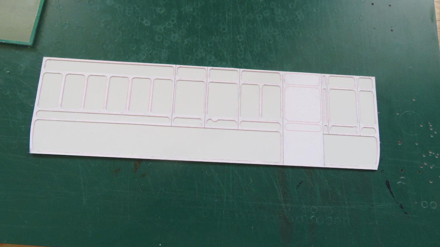
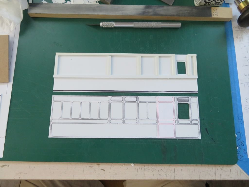
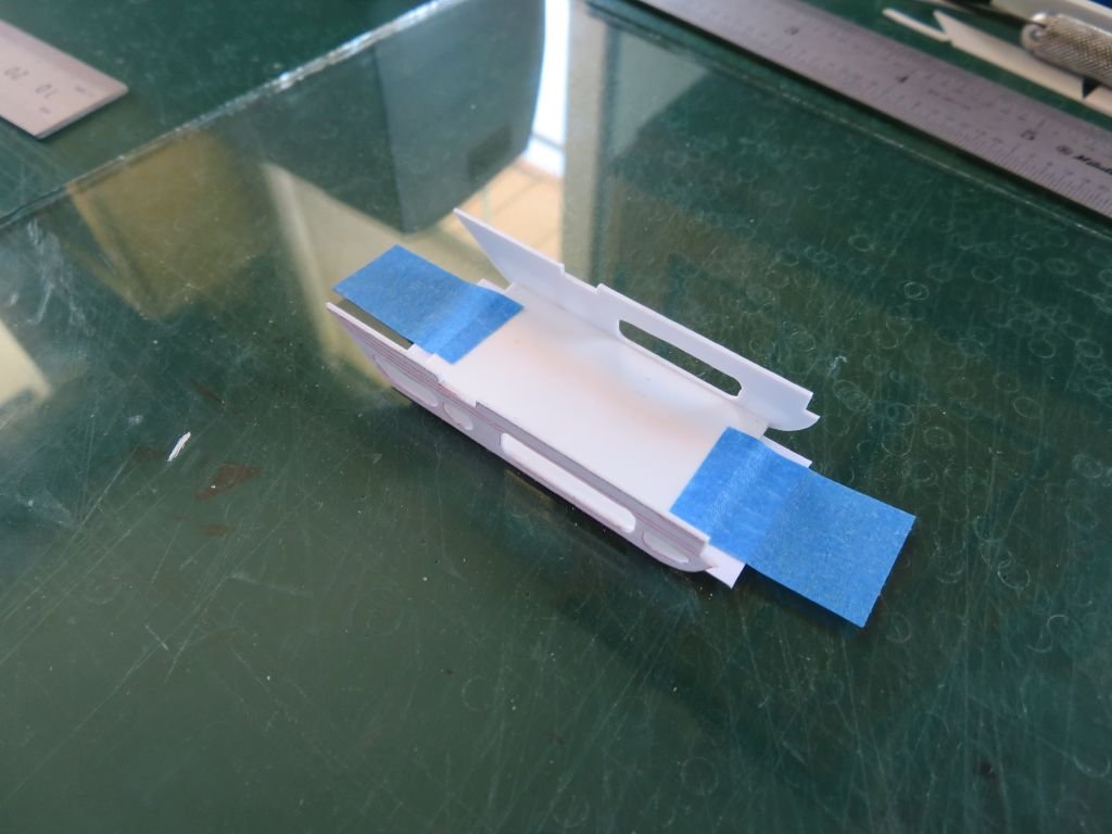
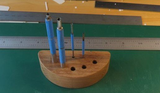
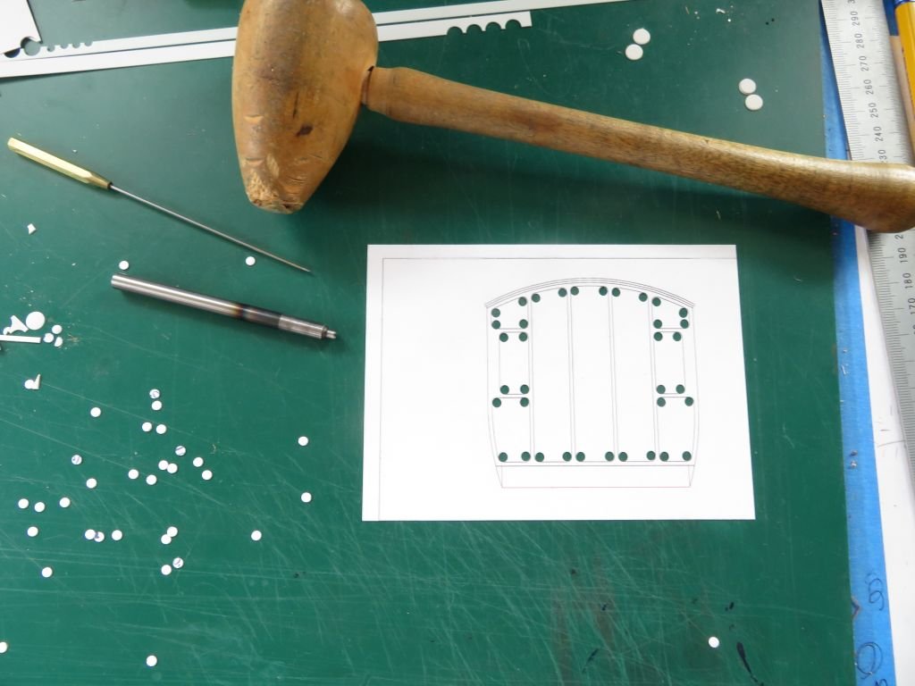
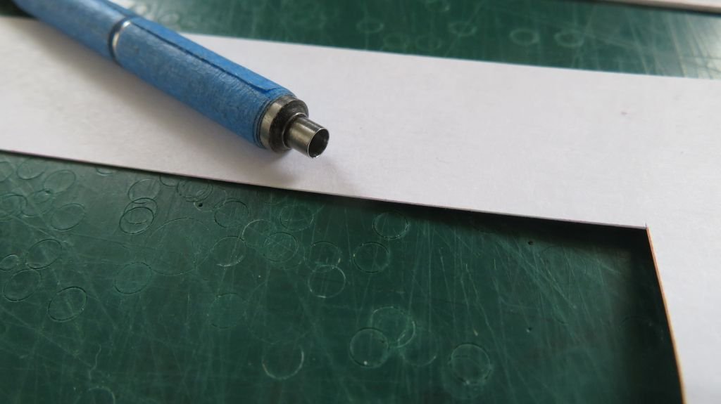
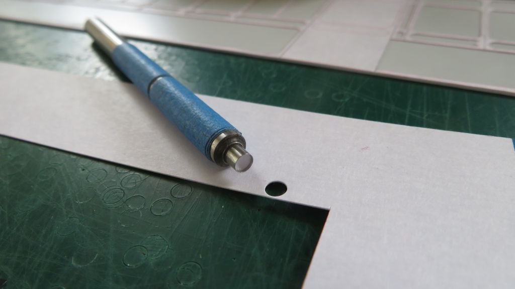
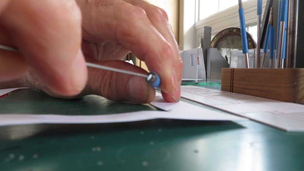
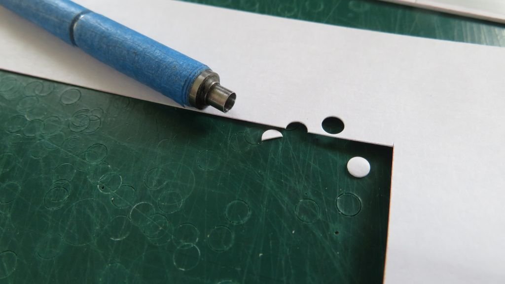
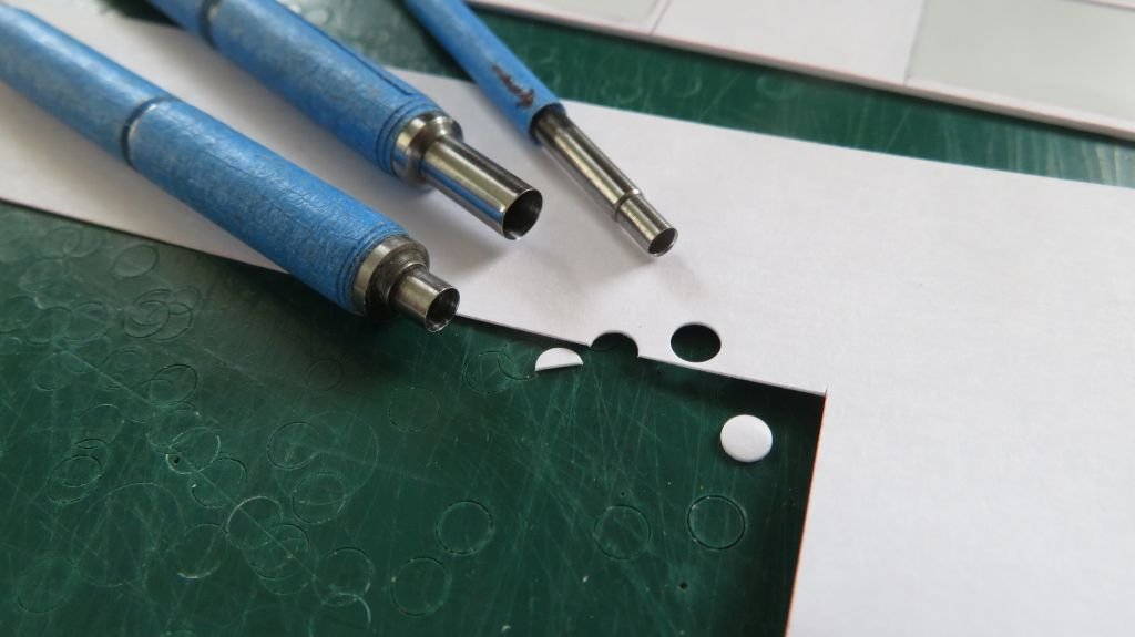
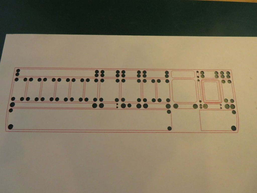
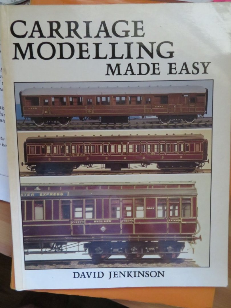
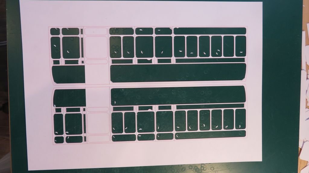
Thank you all for the positive responses. In David Jenkinson's book he does the entire body out of Styrene sheet stock. The outer panel layer out of .015" for gauge 1 (1/32) and .010" for O gauge (7mm scale) these are primarily English scales. here are the common scales and gauges for clarification I found that David's method of cutting out the "doily" or panel layer to be very hard on my wrists he draws on the styrene after giving it a light buffing with some 400 grit to give it a key. then using a Swan Morton scalpel cuts out the panels leaving a 45 degree mitre at the corners, and then uses rat tail files to create the rounded corners. Needless to say this is not easy to accomplish, I made one "doily' this way before giving up and deciding that there was a better way. so I made these The first time I used them was great but they kept slipping so I wrapped some blue tape around to facilitate an easy grip. and began with an end panel, you can see the punch in its original form. also I used some printable cardstock so that I could eliminate the drawing by hand on the card Because the punches are small and home made they need to be cleared which although not difficult is a pain because it is slow. However if the punch only has to cut out the curve of the mitered corner things go a lot more swiftly, as the piece tends to drop out on its own more time than not. Here is a new set of Panel "doilies" being cut by first following David's method of cutting the bulk of the straight lines out first leaving the miters in the corners and then using the punches to round off the corners in the cardstock. This was a much smoother way to do this and my previous experiments with gluing the cardstock to the styrene proved to work just fine. I used Methyl Ethyl Ketone (MEK) to bond the card to the styrene as it capillaries so well. And last one of the panels glued and trimmed ready for the next steps. That's all for the moment. Michael

- 17 replies
-
- 14
-
-

-
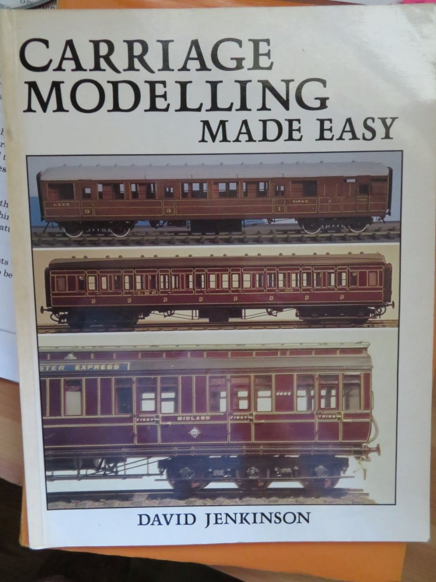
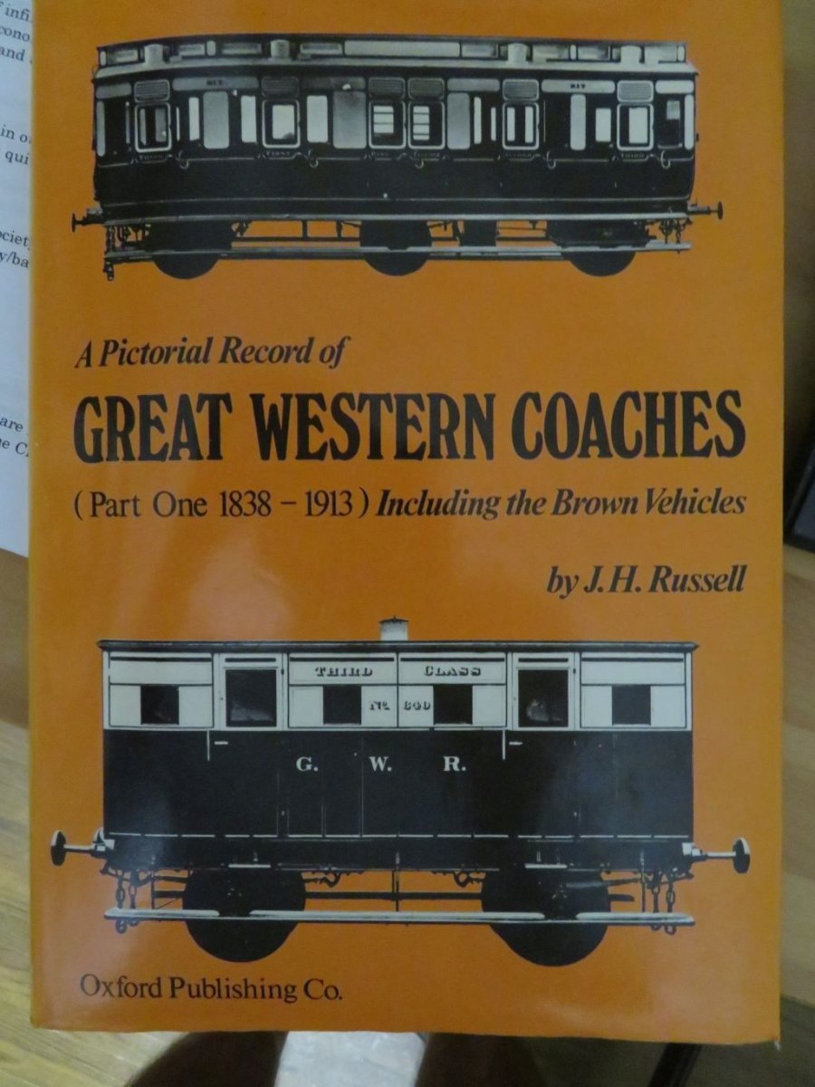
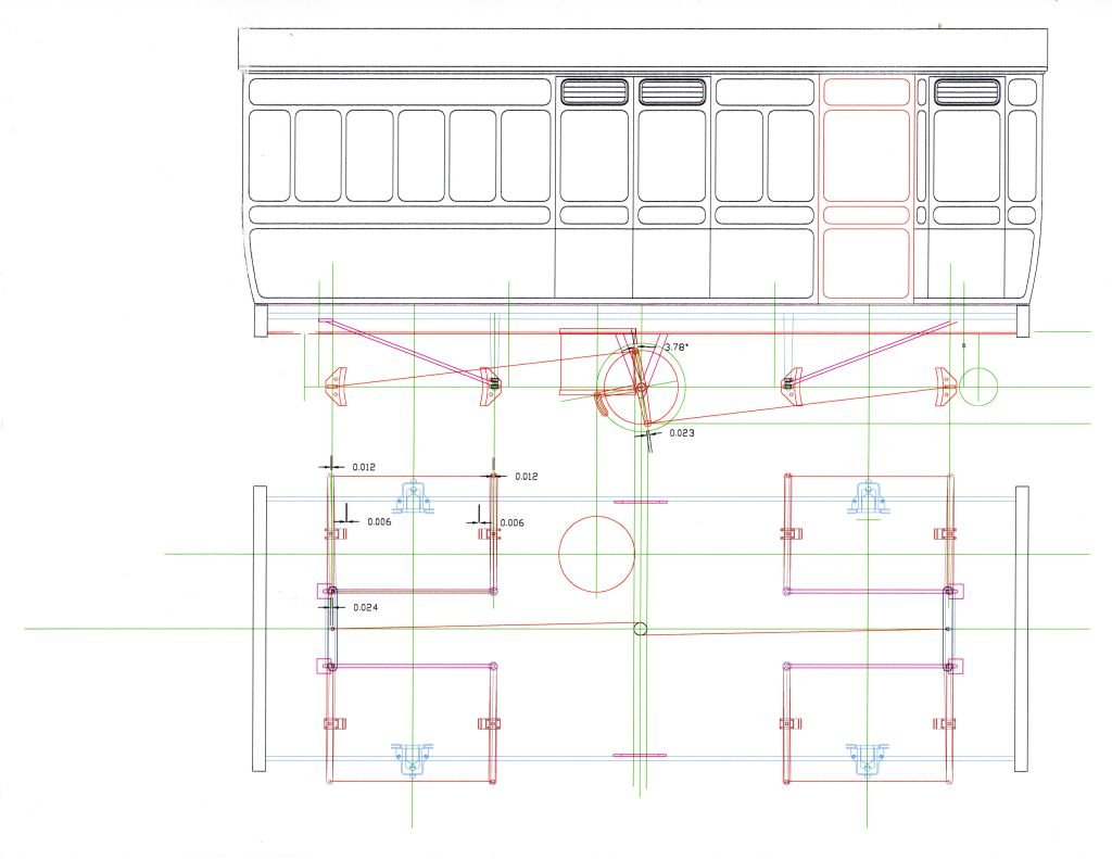
As suggested I will begin here. My boat building mojo is having a rest while i indulge my other main interest building odd and interesting railway models. This build will be a one off scale model of the GWR parcel van built in 1876, I am using as the main reference the pictorial record of GWR coaches by J. H. Russell From the information in the book i am compiling my own drawings which are a work in progress. Some early test pieces to work out my buildimg methodology, leaning heavily on the work of David Jenkinson who wrote a great book about making carriages out of styrene plastic. it is late so I shall continue tomorrow. Michael

- 17 replies
-
- 19
-
-
Thank you Keith, Eberhard, and Druxey. Keith thanks for your kind words. Eberhard, yes the information is not exactly great, a mix of photographs of some existing coaches and tiny drawings in a pictorial about the GWR coaches. I Like your Hint Druxey. Michael
-
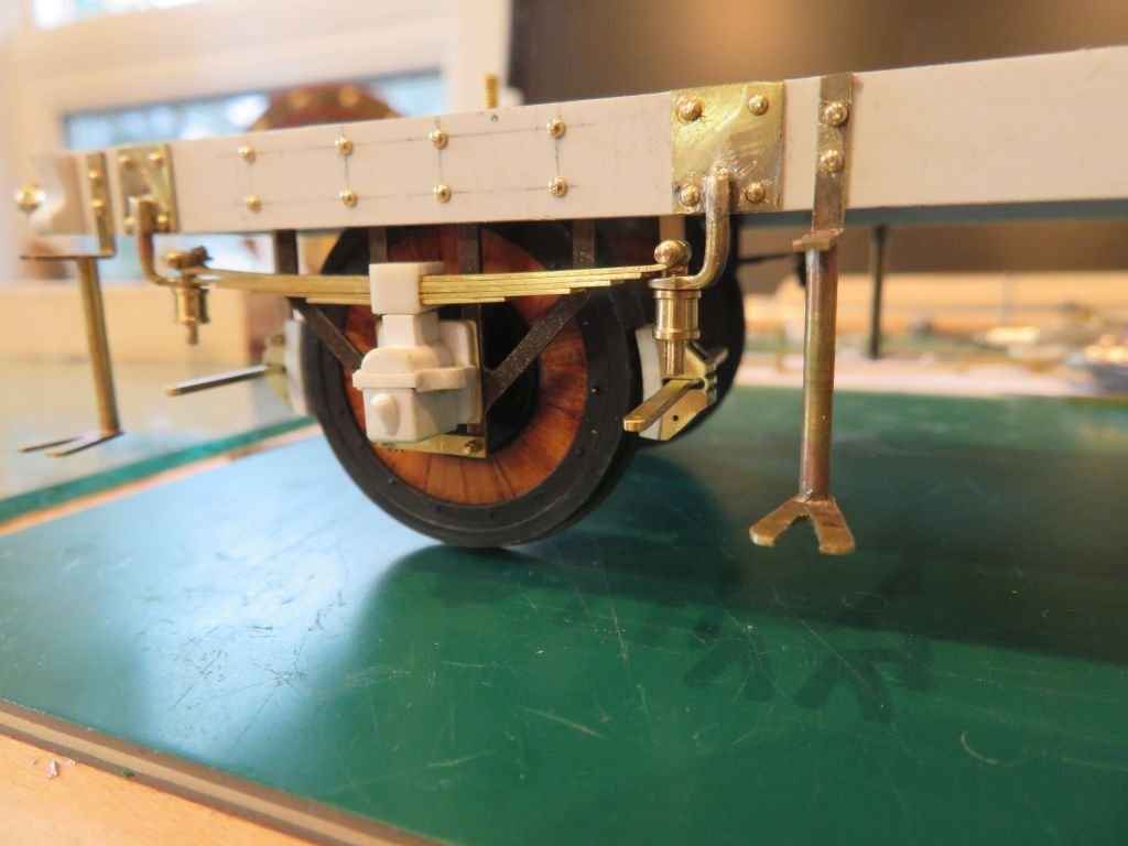
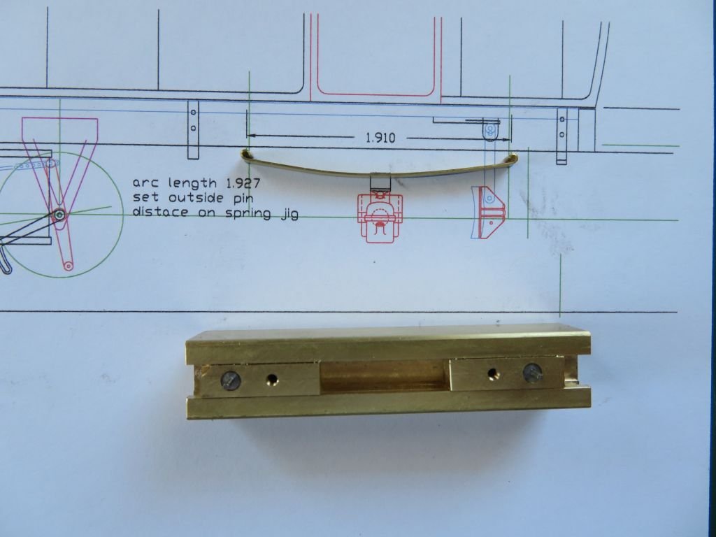
Hello to you all who have expressed concern for my health. First of all my surgery went well and my hand is back to normal working with the tools I love most the jewelers saw and my Myford lathe, opposite ends of the model-making spectrum. Judy and I have been keeping a low profile during the last couple of years for all the obvious reasons. My model boat building has taken a back seat at the moment, even though the cutter is not 3 feet away from my bench and the stern is only 9 inches from the end of the lathe bed. As many of you know I am also an avid builder of model railway subjects, currently in the front seat. ( I am working on a four wheel coach of the Great Western Railway built in 1876 in 1/32nd scale and it has presented a great deal of challenges. I am not likely to build any more of them. this one with full working clasp brakes, is enough for me.) Here are a few of pictures of it. the body is .030" styrene sheet with a printable card-stock overlay cemented with MEK to the styrene. The wheels are a composite of steel Castello (16 wedges) and brass all the bolts and pins are turned from brass stock, the axle-boxes and hangers for the springs are currently being redone to better reflect reality, with proper cups and rubber bushings. And the adjustable jig for bending the loops on the ends of the top leaf of the springs. I think I better not push my luck posting pictures of model railway stuff on this Bristol Cutter build log. I am sure that my boat building MOJO will be back sooner rather than later and I will get on with the galley and map chart area. perhaps a sextant lying on the table with some compasses and a parallel rule and pencil. Michael
-
NAIAD 1797 by Bitao - 1:60
michael mott replied to Bitao's topic in - Build logs for subjects built 1751 - 1800
Lovely work on the chain pumps Bitao. Michael -
Keith they are just visible in some of the photos of the real boat. Michael