HOLIDAY DONATION DRIVE - SUPPORT MSW - DO YOUR PART TO KEEP THIS GREAT FORUM GOING! (Only 36 donations so far out of 49,000 members - C'mon guys!)
×


michael mott
-
Posts
5,198 -
Joined
-
Last visited
Content Type
Profiles
Forums
Gallery
Events
Everything posted by michael mott
-
 Hi Rob Not intending to hijack your fantastic thread but I thought you might like to see this coaster I just cut this morning for you, it was a lightning cut, only took me a bout a year or so to do. It will go in the mail today. I am assuming your address is the same as the one you PM'ed to me earlier. sorry for the long delay I accasionally suffer from bouts of procrastination. Cheers Michael
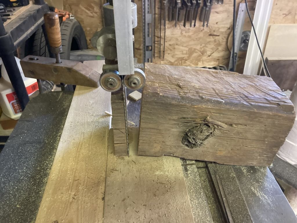
- 3,560 replies
-
- 2
-

-
- clipper
- hull model
- (and 2 more)
-
I think that is the thing that many of us forget when struggling to portray a moment in time, which is what our models are really all about in my humble opinion. That said it is wonderful when the model can use the miniature of the real full sized object being modeled. But here's the thing we cannot scale molecules and an element of nature is what it is. We compromise all the time to make something look as real as possible in miniature, And you my friend have done an amazing job in representing all those furled sails. Oh but I did notice the stitching was a bit loose on the clew of the mizzen sail.😉 Brilliant work Rob!! Michael
- 3,560 replies
-
- 3
-
-
- clipper
- hull model
- (and 2 more)
-
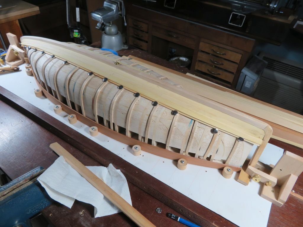
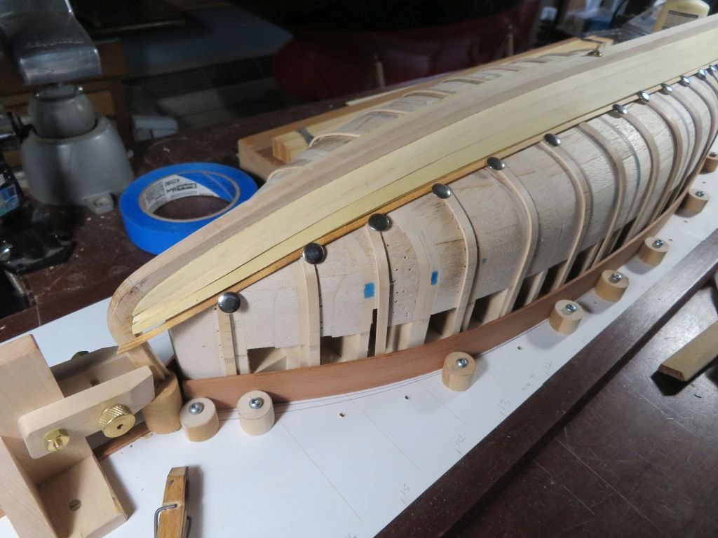
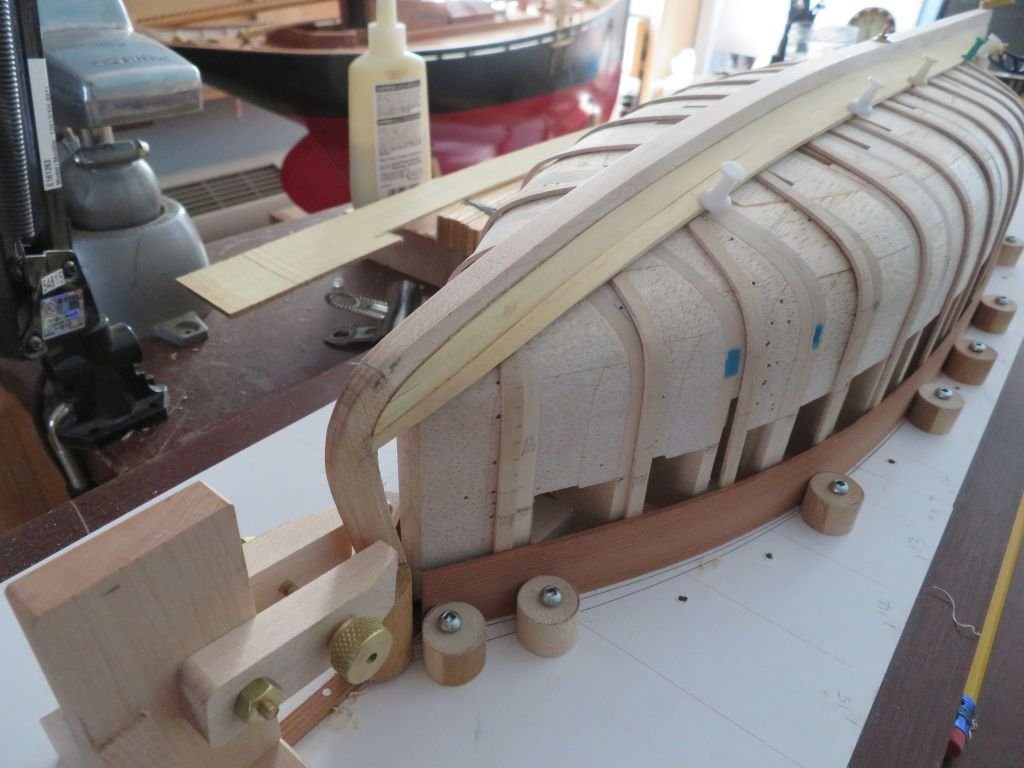
I have added a few more planks. This planking is far more stressful that when I planked up the cutter, because on that hull it was all strip planked and on this hull I am trying to follow the real planking as best as I can, so it is a little bit slower going. Michael
-
Hello Geert I too missed the last part of your build, Wonderful work and the finished model is a nice reminder of the working vessels that supplied some of the food in past times. It is nice to see all the little details that you have been able to include, well done all round. I will now go look at the gallery. Michael
- 219 replies
-
- 3
-
-
- smack
- cross-section
- (and 2 more)
-
A small update the third plank on the port side The gluing went well, eventually, I did have to clean it all off the forward half mage a small adjustment to the length then re glue. Michael

-
Valeriy, I have just been catching up, so apologies for all the likes. Wow you have been accomplishing an amazing amount of superb work, with difficult news all around. Your attention to the small details are what make your work so compelling to study. I am sure that for some of the small repetitive details it is like a meditation, that carries you away. An exquisite body of work so far on this model, you raise the bar high for all of us. Stay safe . Michael
-
Rob the furled sales on the boom look great. It used to be a job on my small Maria neatly folding up the main between the gaff and the boom, I can imaging it must have been quite a job on a big ship, yours looks very realistic. Michael
-
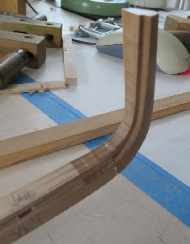
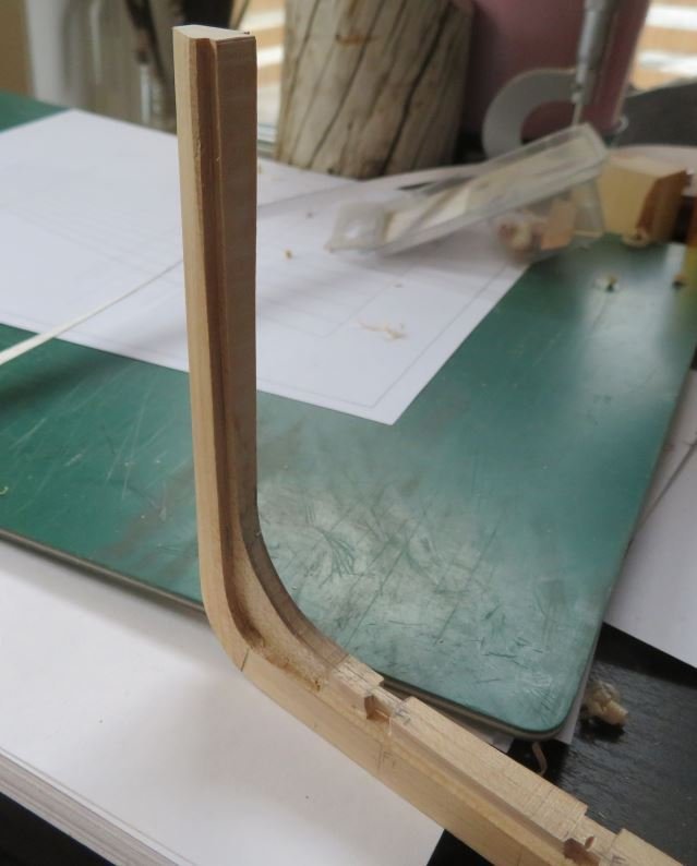
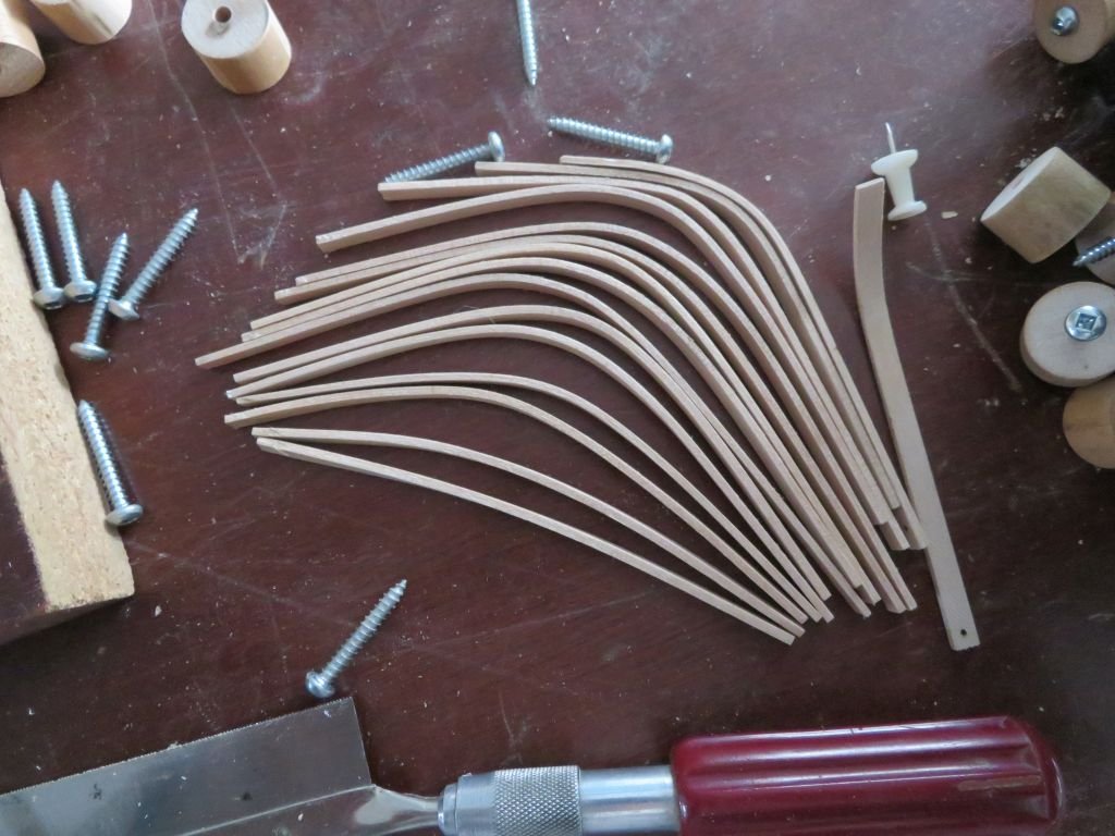
Well a bit more adventurous today John, I did manage the second plank on the starboard side in a single piece, however I think I will continue with using 2 or three pieces just to allow the gluing to be less stressful on my nerves. On the third plank on the port side I chose to cut it amidships and work from each end. first however I used some regular thumbtacks to lay a batten along the tick marks, which made creating a tracing a little easier. Transferred it onto a rough slab of yellow cedar. Chopped it in half and worked at forming each end with the mini hut air gun, I will let it sit overnight and see how it looks in the morning. The nice thing about the batten is I was able the drop the formed plank into the gap. Looks like I will need to twists the stem end just a little more tomorrow, it is just resting there at the moment. Michael
-
No doubt...... Michael
-
Gary this is a very good way to get a lot of subtle soft curves and I can attest to it working extremely well. I used this method to finish shaping a pull saw handle made of birds eye Maple. and the edge stays sharp for a long time. Getting to the final shaping must feel really great Alan. It looks good, and I like your tilting table. and the plant stands. Michael
-
Modelling locks or Latches
michael mott replied to jackieofalltrades's topic in Metal Work, Soldering and Metal Fittings
Yes, welcome Patrick and thank you for your kind comment. Michael -
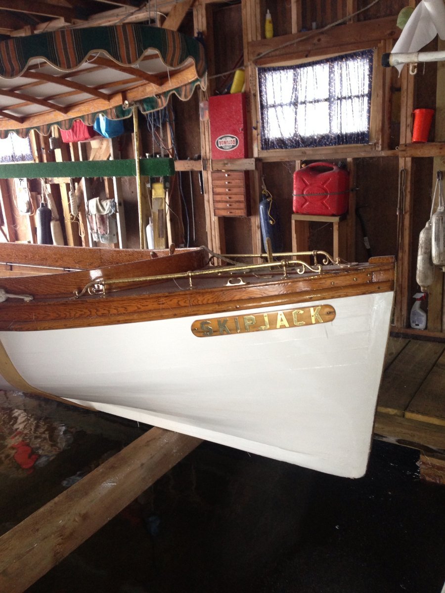
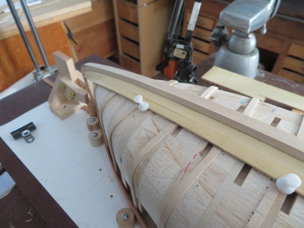
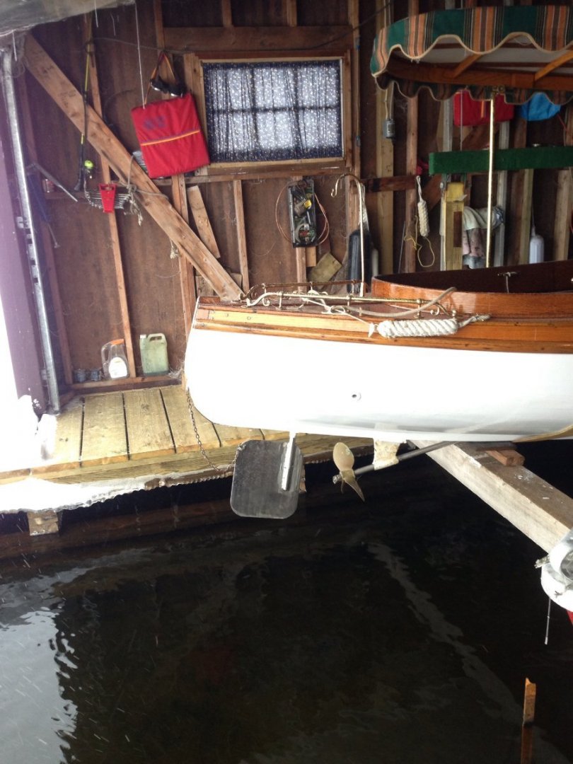
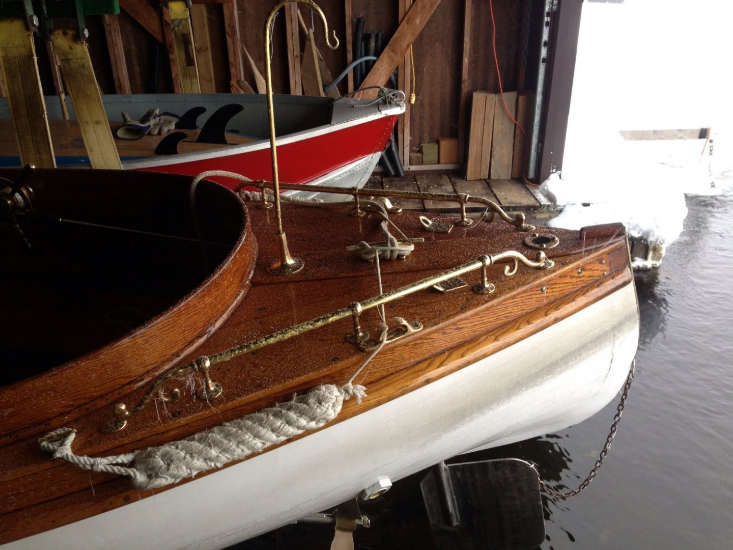
Thanks for kind comments and likes. The second plank was more difficult than the first, I ended up making it too short so cut it into three pieces and replaced the bow section. One plank was enough for me today. When looking at folk who place the planks on the full size craft there is a few guys and lots of clamps. we are spoiled with our super sized hands and strength relatively speaking as we plank up our models. That's my rational for the extra clamp and the holding pins! here are a couple of shots of the full size stern and stem credit to Roger Dymont who gave me permission to use the photographs. I think I will need to do more shaping of the stem and stern once the planking is complete. Michael

-
Hi Mark, yes the pictures of the original hull do give some rather deceptive assurances, but the shape is a challenge especially with the first few planks. There is a lot of twisting at the stern. I am also going to have to hollow out a few of the planks which will be new for me. When I planked the cutter I did not follow traditional planking but strip planked it so it was easy. This hull is more challenging because I am trying to build the hull with the best guess about the hull shape from the information supplied by the owner in terms of measurements, and photographs, without actually checking some of these shapes and forms myself. There are no drawings to go on other than my own culled from the information given by the owner. Michael
-
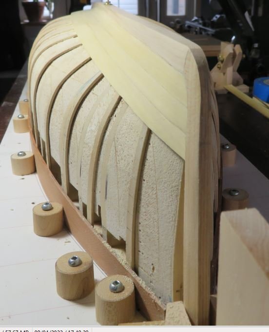
Thanks for the likes. I glued the garboards today , not perfect by any stretch of the imagination but will have to do. Tomorrow I begin the layout of the next couple of planks. Michael
-
Hi Druxey the yellow cedar is 3/4 inch scale so 3/32" in "real money" According to Roger the chap who did some repair work on Skipjack told him that because the yellow cedar was not as strong as mahogany that the builders used 3/4 planking instead of the usual 3/8ths. I purchased a couple of lengths of 2x6 Yellow cedar from the local wood supplier. I planed one edge then band-sawed of the plank about an 1/8th then planed the edge again and cut another plank and so on. after the plank was cut to shape I planed it down to the 3/32 with my Veritas low andgle bloch plane. before bending it. Michael
-
Lovely planking job Keith of course the brass work is up to your usual standard as always. Michael
-
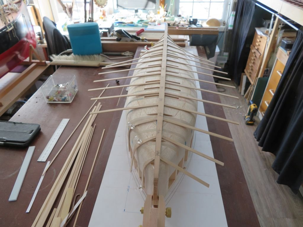
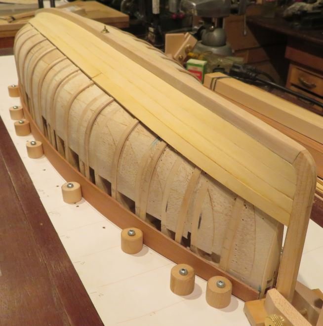
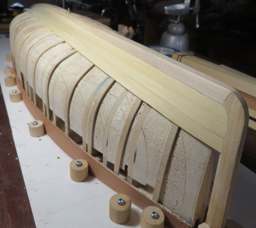
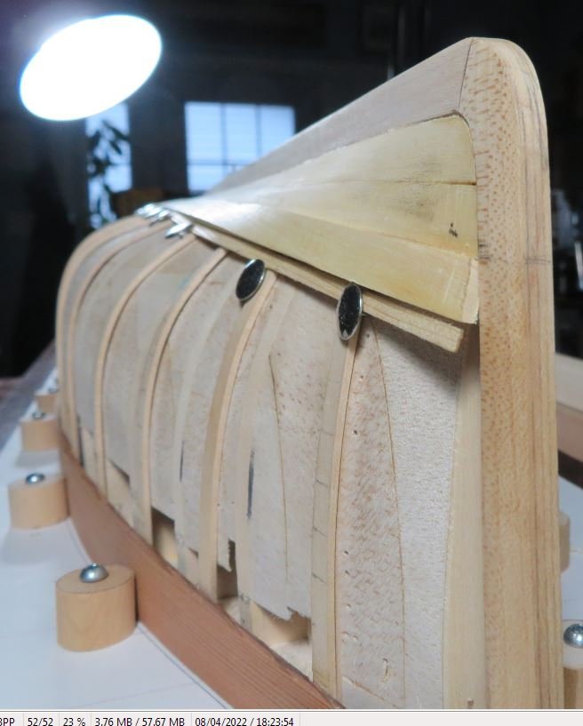
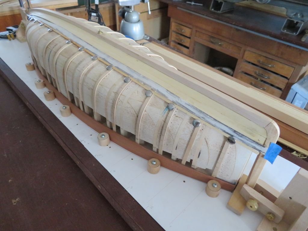
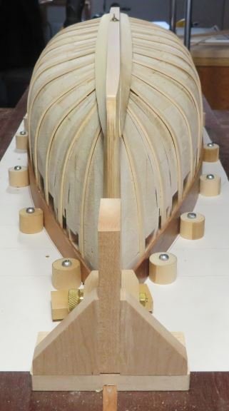
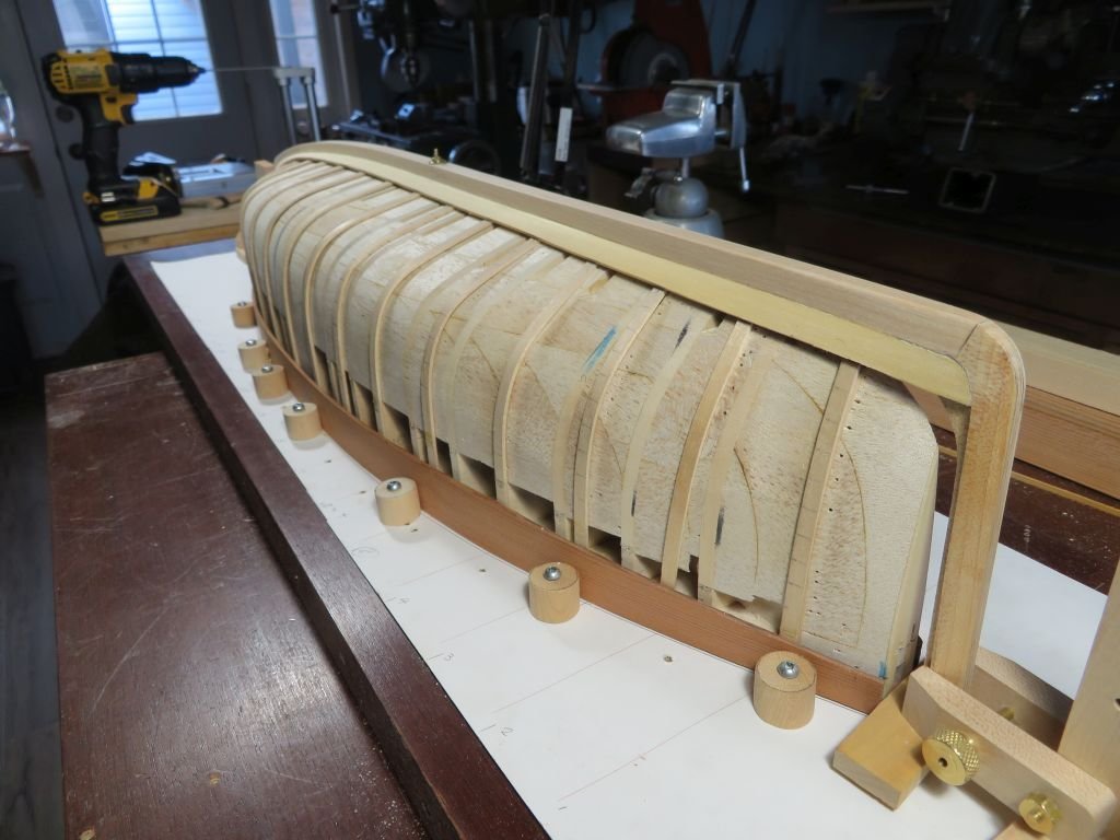
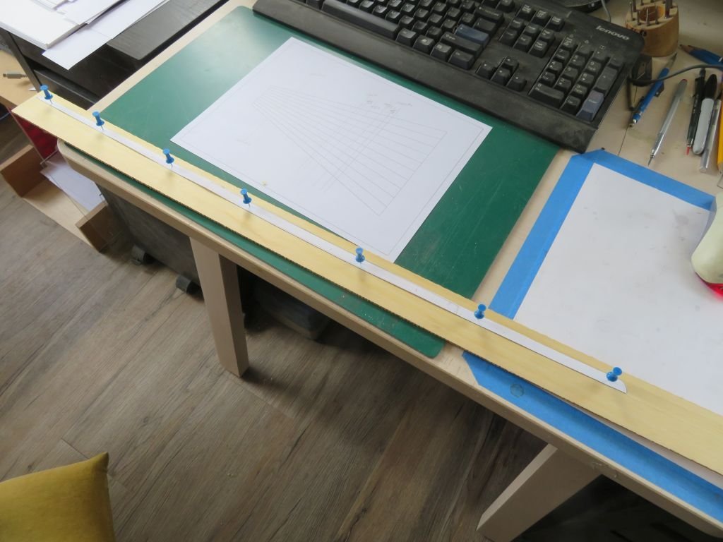
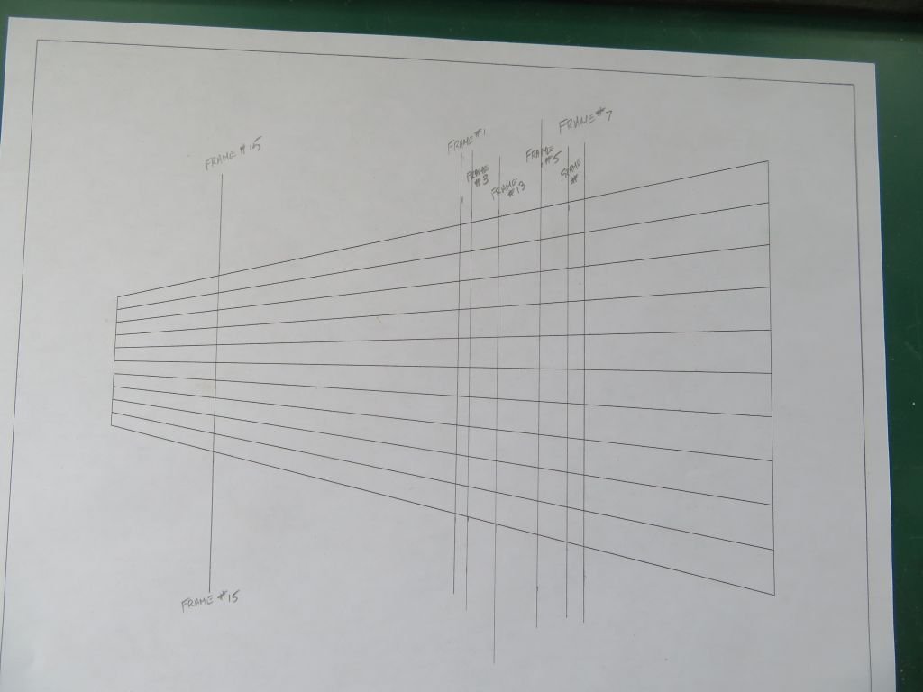
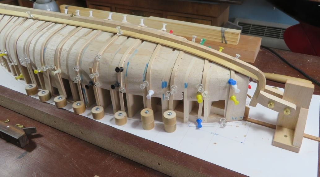
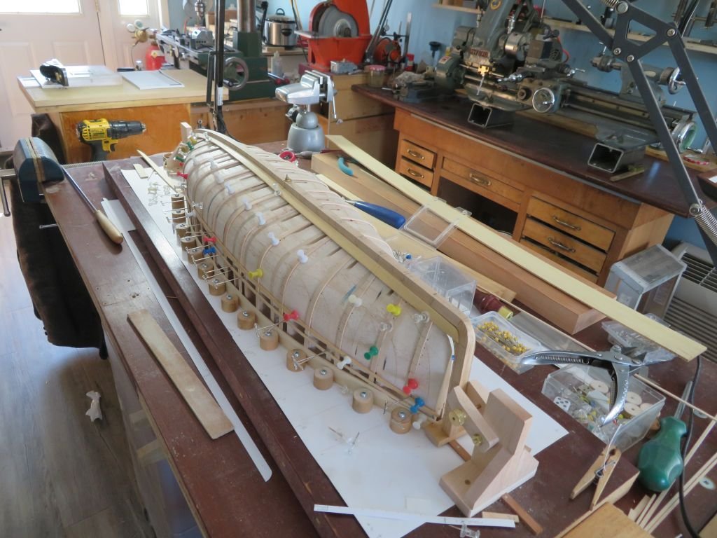
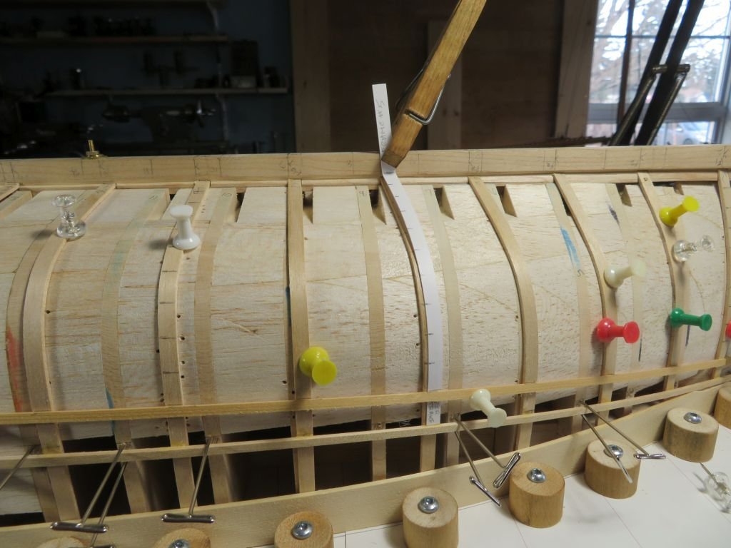
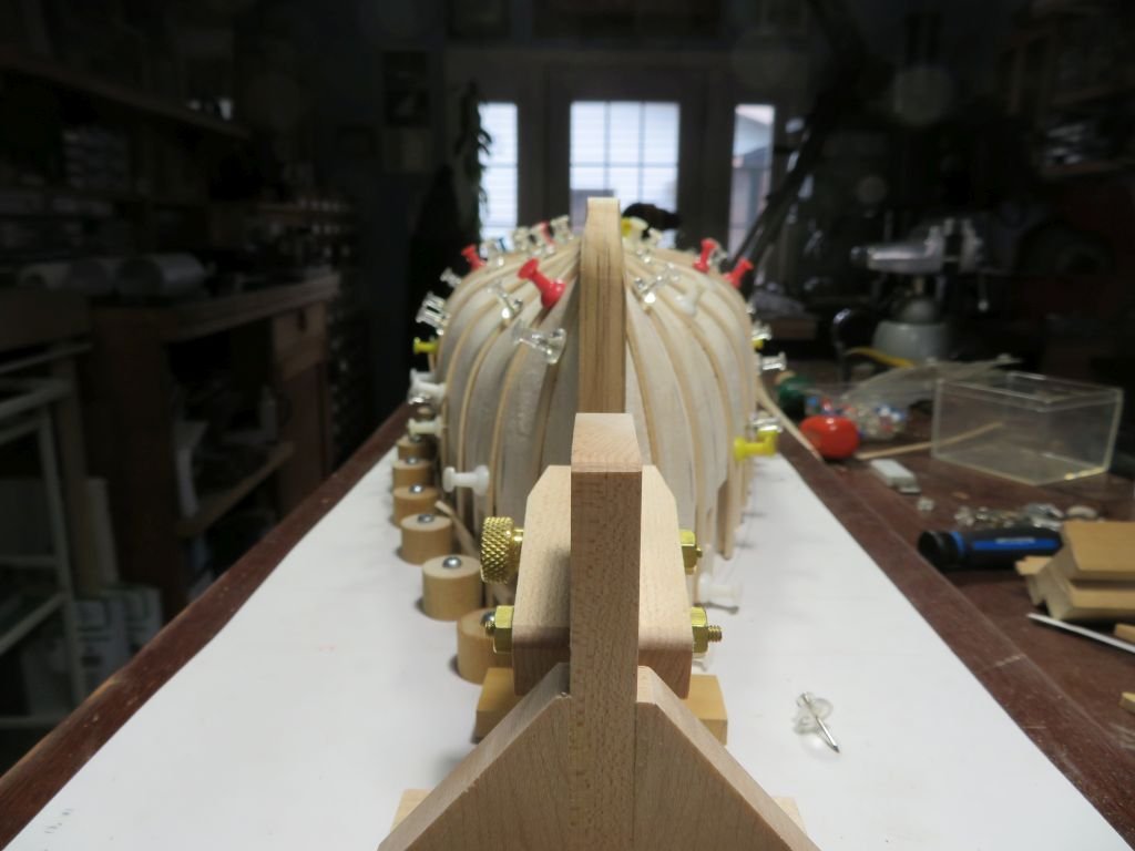
A better day was had on Sunday, the most tiresome aspect was keeping the young cats out of the workshop as I travelled back and forth from the kitchen Microwave and the workshop. I had to carry a squirt bottle with me on every trip to stop them dashing through the door every time I opened it. Before all the trouble with the stern post I had worked on both of the garboards and they are quite close just a bit more tweaking before setting them with glue. As I mentioned I used the strip method to marl the frames with the position of the planks, the one thing I did notice with this method was that with the frames that were canted forward or aft at the bow and stern the tick marks were angled quite noticeably. so I used the center as the datum point. This is the chart I set up to calibrate the spacing I did not mark every frame but every second frame. I used some stiff card paper to lay out the garboards then transfered that to the 3/4" (scale) thick yellow cedar that I cut earlier from the 2" rough lumber flipped it for the opposite side and cut them out with the bandsaw, and used the miniature lee valley wood plane to finish the edges. I just used the big hot air gun and twisting with gloved fingers to shape the garboards. After the stern post incident I took the opportunity to revisit the frames and basically re-bent most of them, I had forgotten the bit about also using my soldering hot air gut to help set the curves as they were drying. When I bent the first frames before my surgery I had also used the hot air gun and it did make a big difference then. While working on the shaping of the stem and stern I cleaned everything off the form and reworked the dowel buttons into cams and cut full length boards of redwood, (these were cut earlier salvaged from the garage door, the same wood as in the Buzzards bay hull) to act as the lower holds for the frames. I decide this morning that I need to also fill the gaps between the station forms at the bottom because the frames most of them fall between the stations and I want to be able to hold them securely as it will be much easier to control the position between the keel and the build board without the use of pins all over the place. as you can see they are basically stable now. A shot of the re glued stern post. And the stem I see I'm going to have another busy day. Michael
-
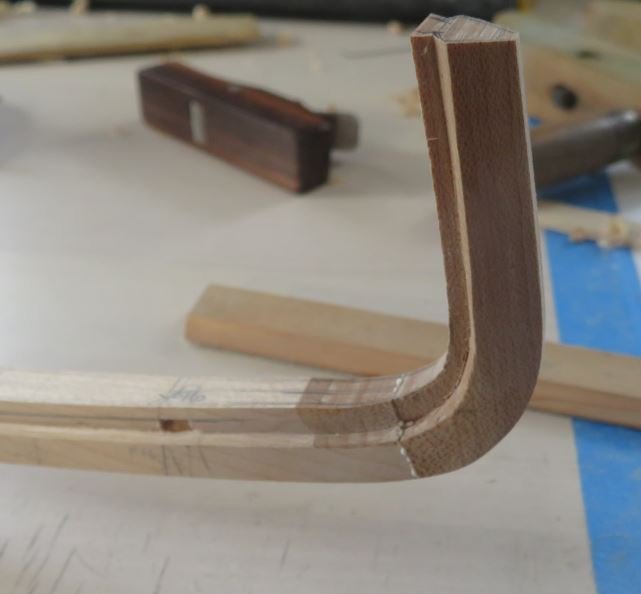
A rather frustrating day, I did get the starboard an port garboards bent to fit and also realized that I needed to shape the stem and stern before going any further when I removed the keel a few, about half of the ribs sprung up like it was spring in the garden. and then I snapped off the stern post while shaping it. I finished shaping it and glued it back on. then using the hot air gun to deal with the ribs had trouble whith them so decided to revisit it in the morning and a new day. Michael
-
Hi Steve can you use a couple of layers the material is quite forgiving really. Michael
-
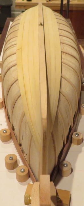
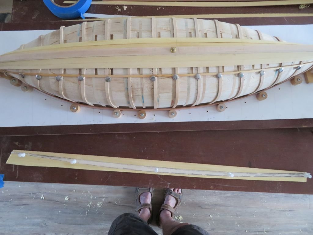
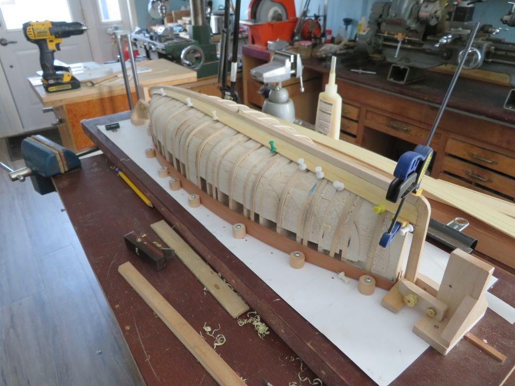
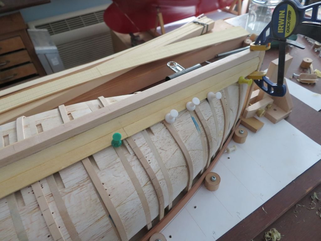
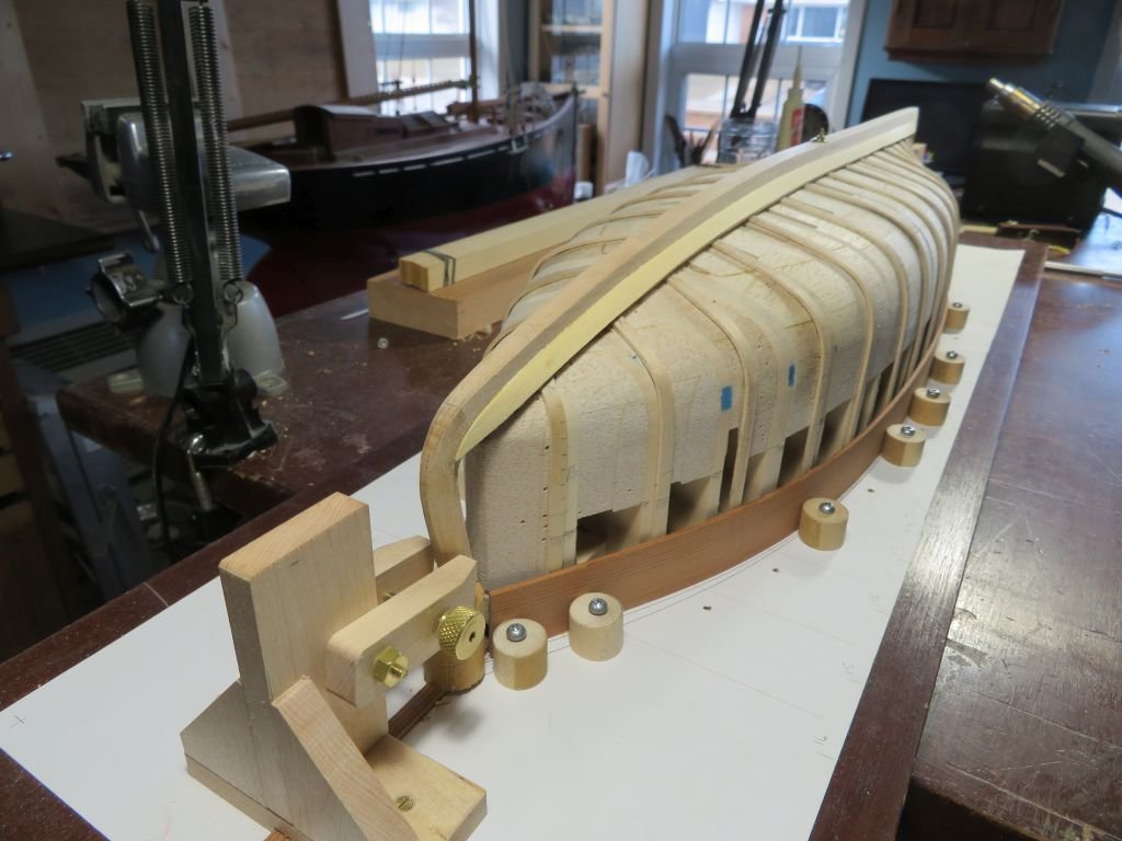
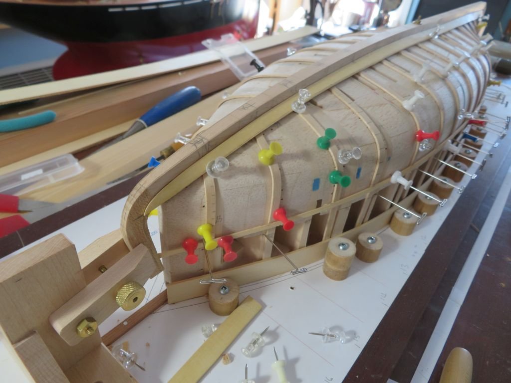
Well the garboard strake is a rather testy little plank isn't it. The old hot air gun works quite well with the yellow cedar. A little bit more tweaking and then this one is a wrap as they say. the plank is just resting there the pins are just to stop it sliding off. I used the strip method to mark the positions of the ten planks. and a long trip to position the bottom of the sheer strake, which is 3iches wide at the bow and stern and 5 inches midships. Michael
-
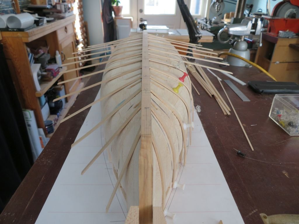
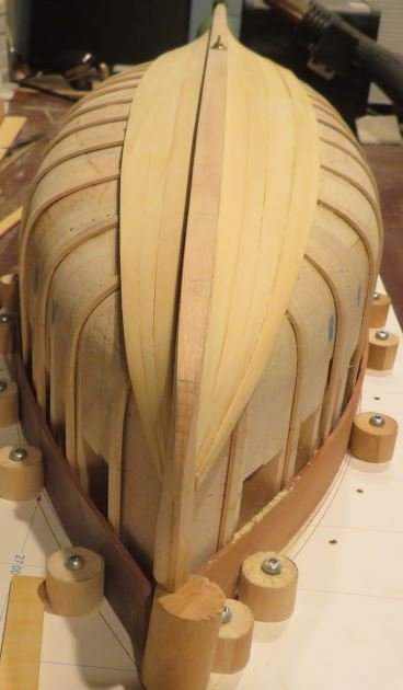
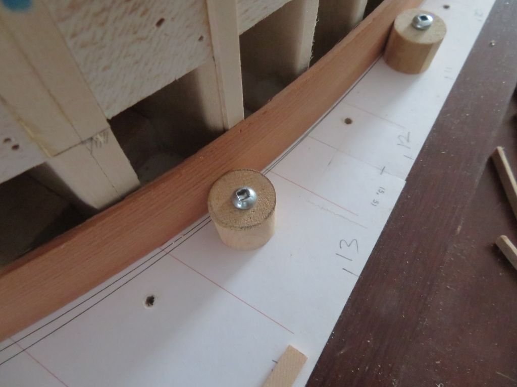
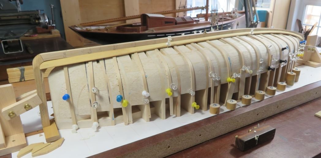
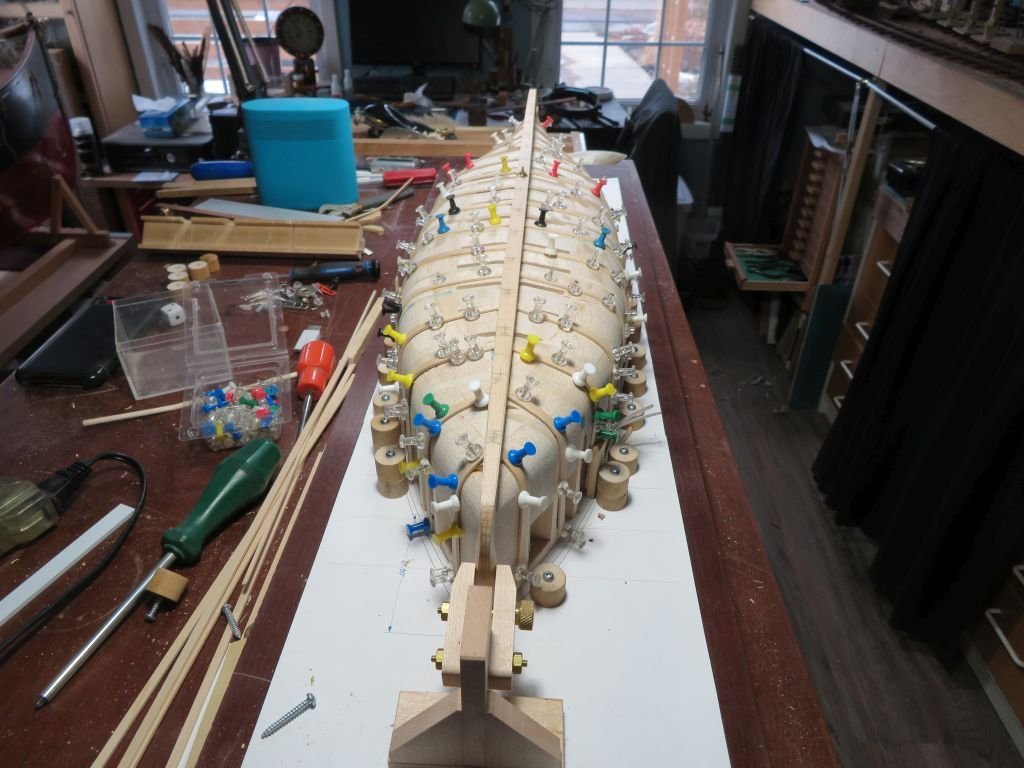
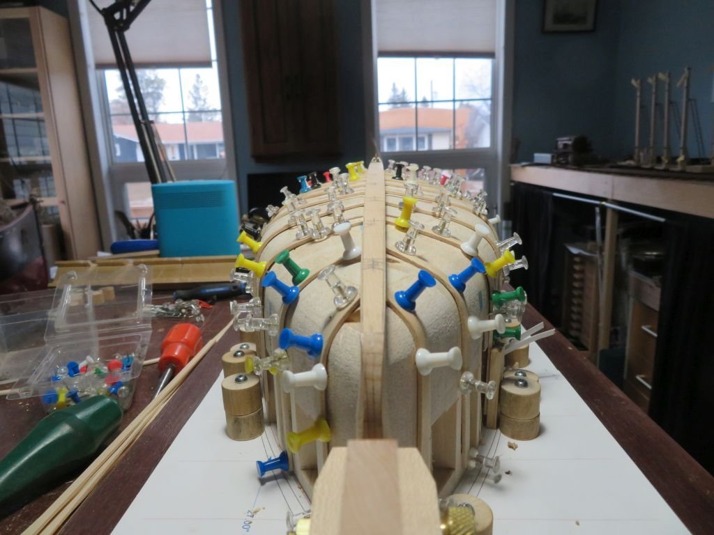
Thank you Pat, and for all those who added a like I really appreciate it. Well the little critter look a bit like Spiny Norman, with apologies to the Dinsdale Brothers and Monty Python. It took most of the day to get things sorted ( but you do what you have to do) and no the round supports are not cams I only thought about that as I started screwing them to the board. I did manage to snap one early this morning, and I attribute it to by placement technique. It feel very good to get to this point. I will let it dry thoroughly before marking off the sheer line and also the rest of the shaping of the stem and stern. Then the real fun begins gluing it all together. Michael
-
Lovely piece of work Toni., I am also curious about the little notations of time between posts I have not seen those before. This model has got me thinking that a cross section of one of the Bristol pilot cutters or a fishing smack would be interesting, and it could be done in a larger scale because it is such a smaller vessel. Michael
-
Tom and they are on the north side so even light as well. This evening my neck is stiff from hunching over the keel chiseling out little pockets most of the day. The microwave will get a work out tomorrow, I think I will take the model into the kitchen to avoid a lot of back and forth to and from the workshop. Plus the sink is there for the damp paper towels, I am looking forward to getting this part done. Michael