gak1965
-
Posts
727 -
Joined
-
Last visited
Content Type
Profiles
Forums
Gallery
Events
Everything posted by gak1965
-
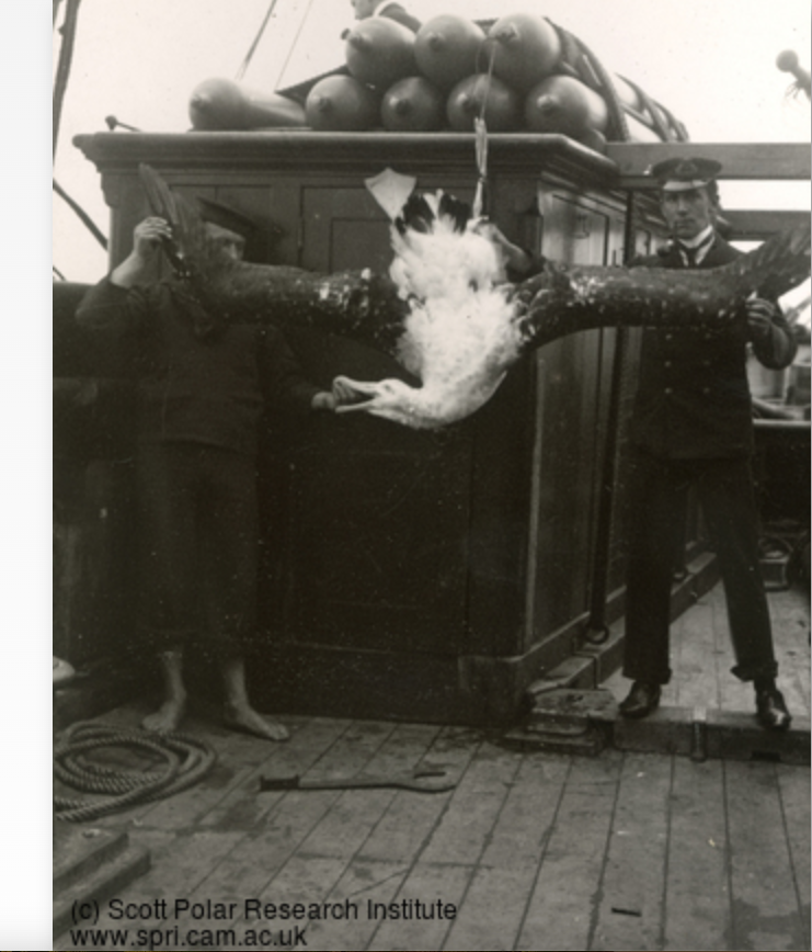
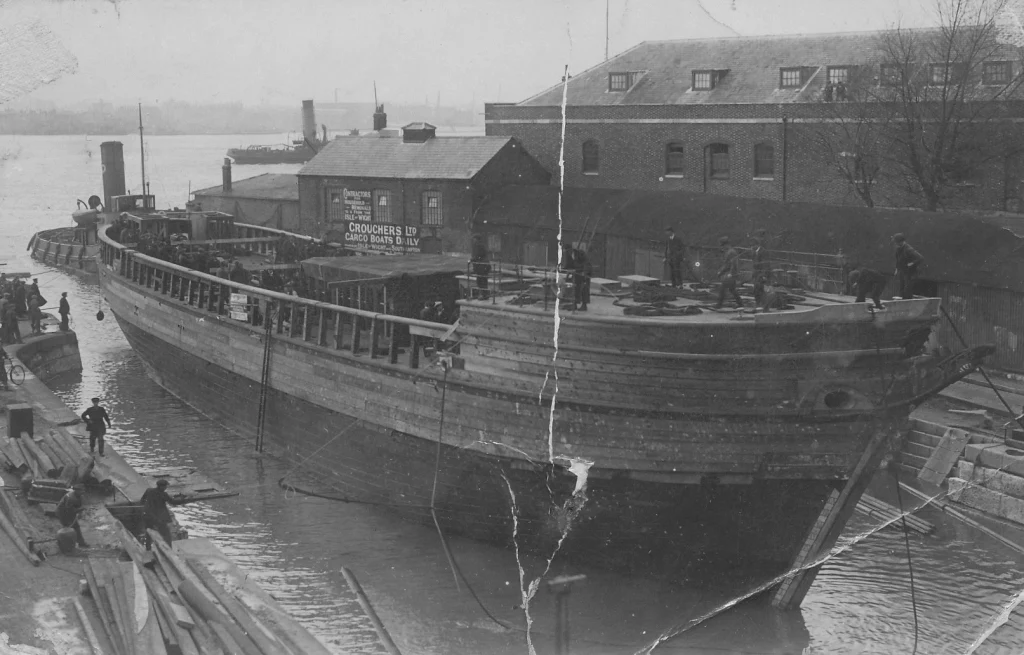
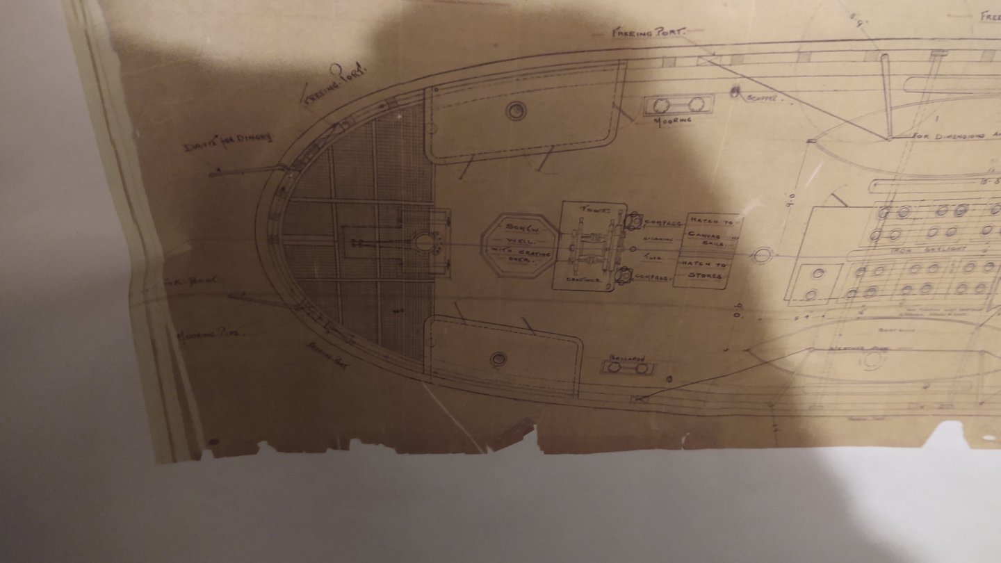
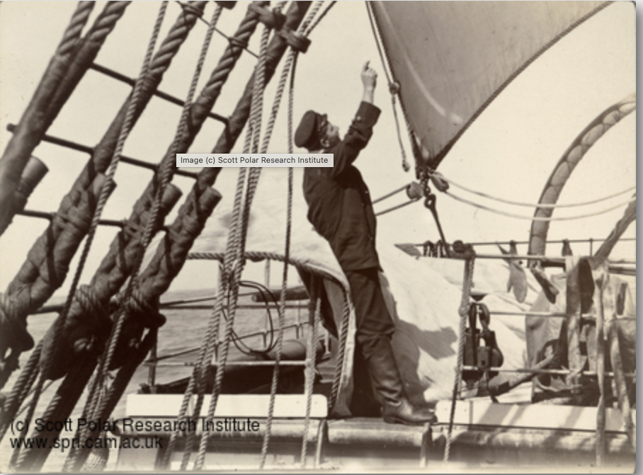
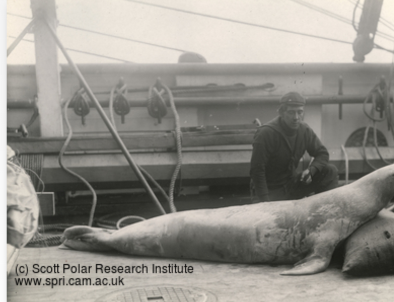
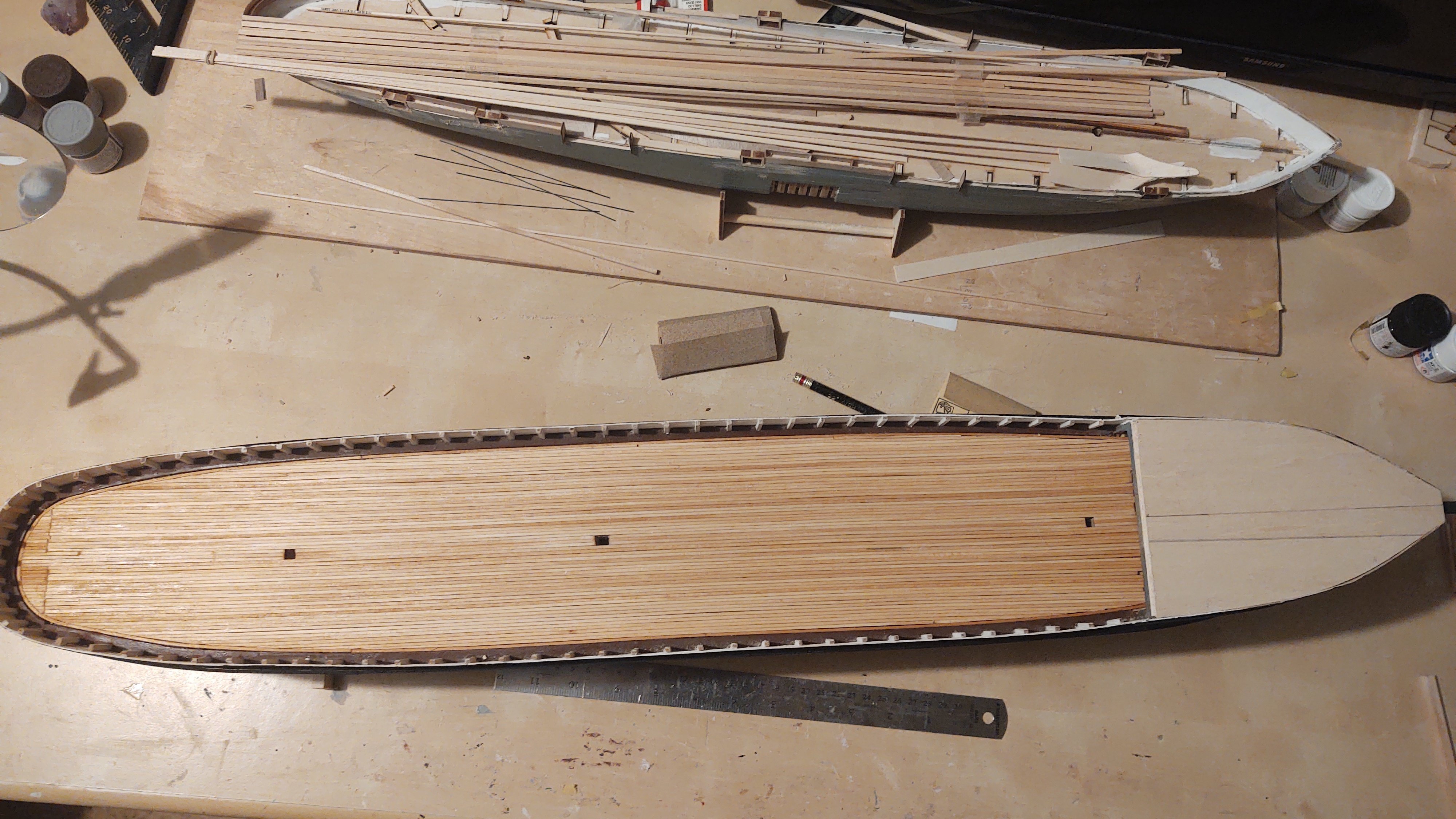
 Thanks Rick! Well, a bit of an update. I've put the main deck planking on. As I mentioned, the junction at the stern is basically in a single joint, but it's going to be covered by a monkey poop, so no one is going to see it at the stern. First, mostly done: And complete: Eagle-eyed observers will note that I fitted a subdeck on the forcastle. I will glue that in place once I've set up the mounting point for the bowsprit and a couple of anchor points for the lower main forestays (which annoyingly mount inside the closed forecastle), and then will put the forecastle deck in place. As an aside, there are two doors into the forecastle from the main deck, which I will not be installing until after the standing rigging is in place, as that is how I intend to get to the forestay anchor points. Given the ship's current state, I thought I would share this one picture from Dundee Heritage Trust. It's of the Discovery in 1923, as she was going in for a refit prior to becoming an oceanographic vessel (and in many ways becoming the ship she is today). I'm pleased that there is a certain resemblance here to the model. I've started thinking about the deck furniture and this has got me deep into questions about how much to trust various sources, and specifically the current ship. As I've shown before, the plans have two deck houses in the stern that butt up against the monkey poop. Between the deck houses are the access port so that you can repair the prop, and the rudder post. Here is a picture of the starboard deckhouse (and a giant albatross) (from the Scott Polar Research Institute) Note a couple of things here. The deckhouse runs right up to the main rail and has doors on the forward side. You will note the officer standing on a rectangular metal conduit - that is the path for the chains that operate the tiller. You will also note that there is a lot of open space. By contrast, here are some pictures of the ship today (all from Wikipedia). Looking forward: And looking aft: The deck houses are smaller, have no forward doors, are closer together (it's jammed up against the access point for the screw, and the steering chains go to the outside of the deckhouse, not the inside) and do not touch the main rail. Bottom line is that as nice as it is to have the real ship around, about the only thing that can be trusted is what is shown in that reconstruction photo above - the hull. Everything else is going to have to come from plans or photos (and ones from 1901-1904, not ones after the 1923 refit). Which is okay, I just need to keep reminding myself. As always, thanks for looking in and the likes. Regards, George
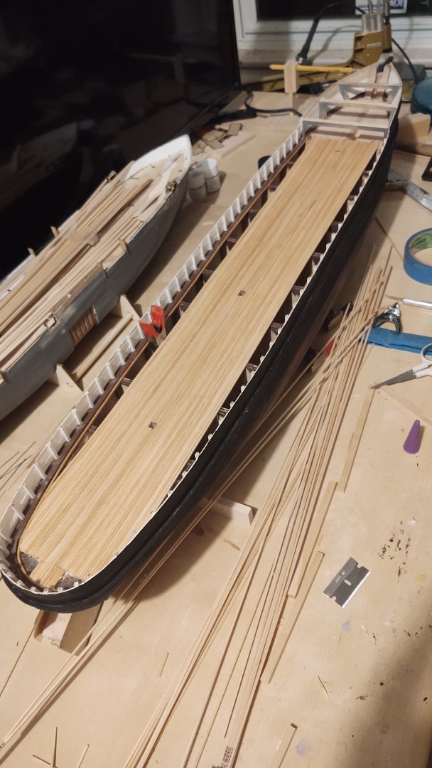


-
Jared, You are really flying through the rigging process! Looking great! Regards, George
- 431 replies
-
- 1
-

-
- Flying Fish
- Model Shipways
- (and 2 more)
-
Thanks Jared. It's coming along slowly, but is starting to look like a ship. Regards, George
-
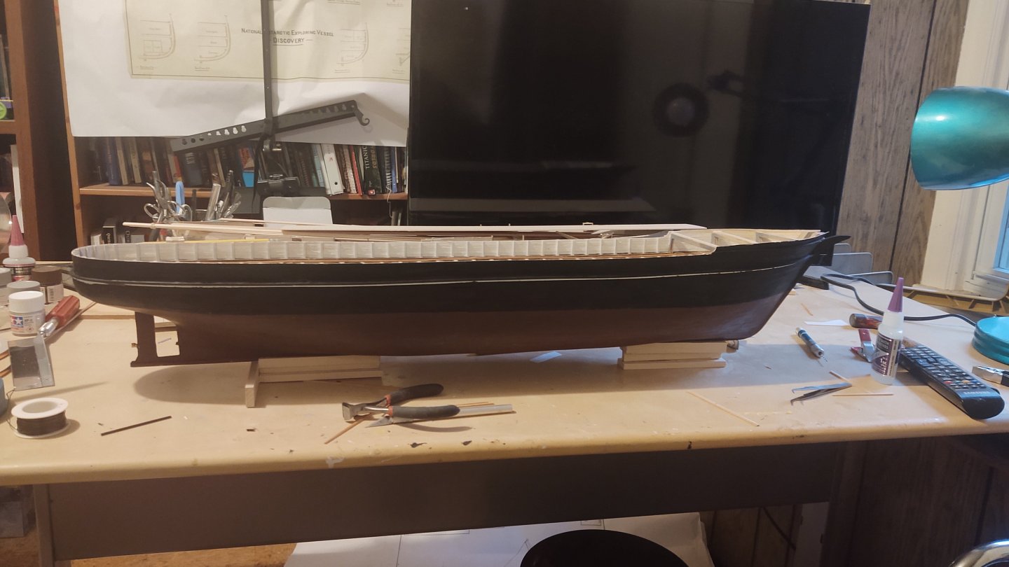
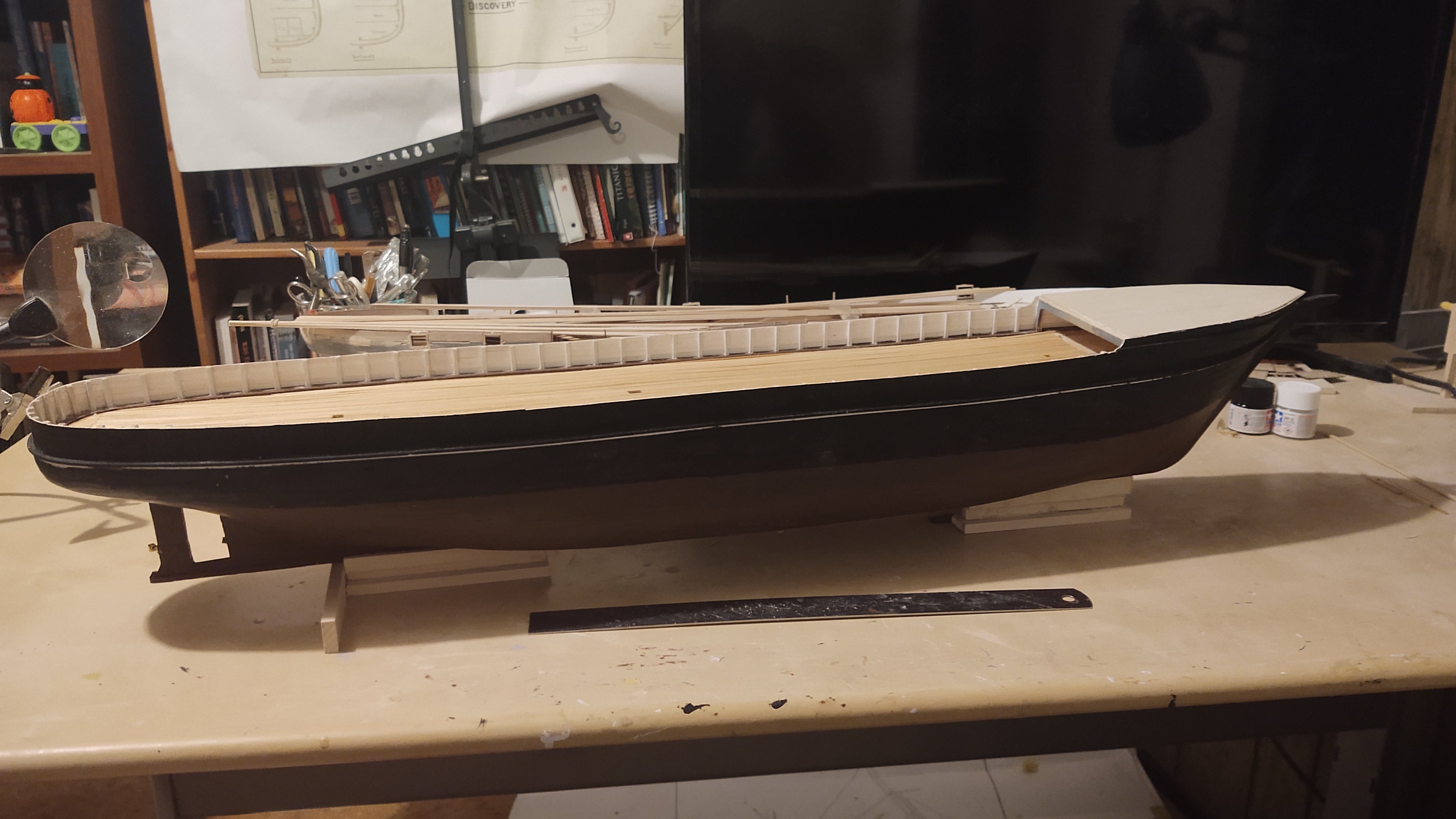
Okay, another brief update. The outer hull is painted. It needs a bit of touch up, but otherwise is in pretty good shape. I've subsequently started the deck. Annoyingly, the main deck needs to be 24.5 inches long, and I can primarily find 24 inch long lumber. So, the question is whether to do a proper, stepped set of planks or to find some alternative. Ultimately I remembered that the last couple of inches of the main deck are covered by a monkey poop and won't really be visible (as seen here): So, bottom line is that I'm just going to join them all at the stern. It's not as neat as staggered joints, but it will be hidden, so, no matter. The forecastle is closed on the Discovery, so the deck only needs to extend a bit forward of the third bulkhead. As always, thanks for looking in and the likes! Regards, George

-
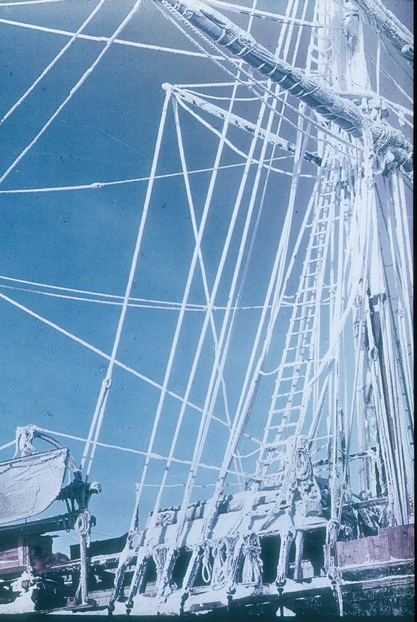
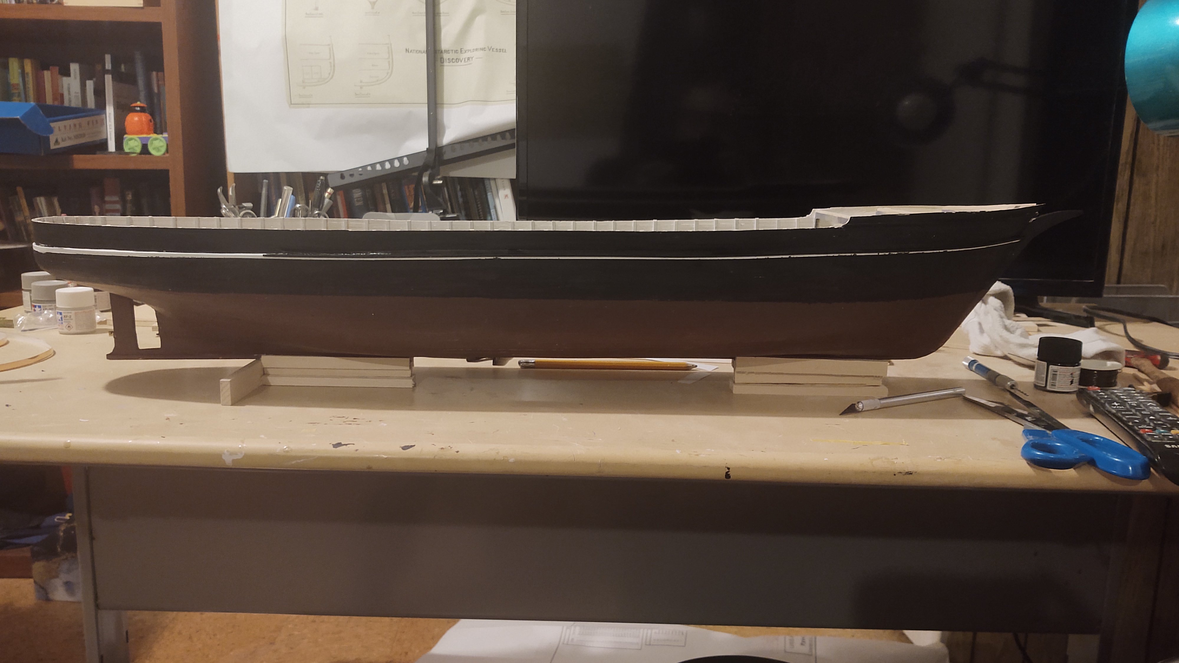
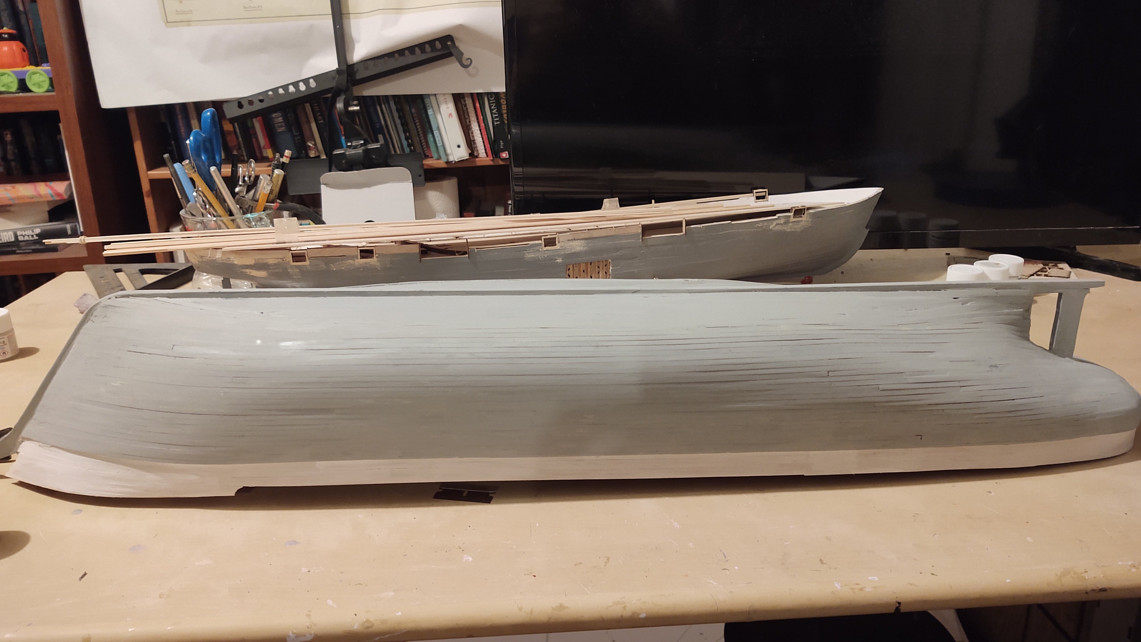
Well, some paint going on the hull. So - the first decision was what color to paint below the load water line. In the end, I decided to use the Tamiya "hull red", which I realize is an IJN color, but it represents a reddish brown lead paint color. And because it is darker, it seems more consistent with the relatively small difference in shading we see on those black and white photos, for example, this one: Here is the model with just the hull red to the load waterline. You will note that I have painted the bulwarks white - not because they are going to end up that color, but because that way I sealed any gaps so when the black paint goes on it will not leak through to the inner bulwarks which are white. Second, you will see that I have painted a 1/8" white stripe just below the bulwarks. As you see in the above photo, there is a white stripe, but that stripe is below a wale on the hull. That wale is going to be made with black painted 1/16 inch square stock that will be attached at the top of the hull stripe, leaving a 1/16 inch (4.5 inches at scale) white stripe as shown above. And here she is with the black paint. You can see that the stripe at the stern is wider. I need to soak and pre-bend a 1/16 strip to go around the stern, and then I will paint the remainder of the bulwark in that area once I can no longer drip onto the lower part of the stripe. Bottom line is that it needs some touchup, but the stripe is in place and I think that the colors are at least a reasonable, defensible choice even if it turns out I am wrong. Thanks for looking in and the likes! Regards, George


-
Do you know how loose the mast was in the socket? To put it another way, do you think you can move it without redrilling the hole? Are you confident that it isn't just being pulled to one side by tension on the shrouds? The lanyards make sense as a first pass if you have enough room between the deadeyes to correct for the lean without making the shrouds and lanyards look too unbalanced compared to the other masts. Sorry to hear this, but it could be worse. The other two masts look nice, straight and aligned Regards, George
-
Thanks Gary! That's my assumption as well, but I still find it amusing in landlocked Wyoming. But, heck, Idaho (!) has one of the larger seaports in the form of Lewiston, more than 450 miles from the ocean on the eastern side of the Cascades, so I shouldn't be so amused I guess. Regards, George
-
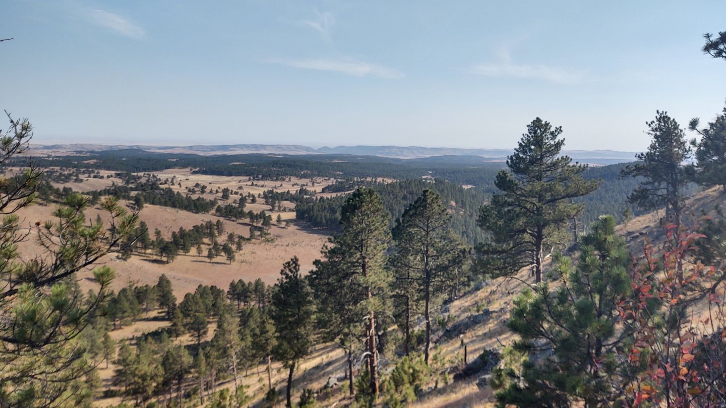
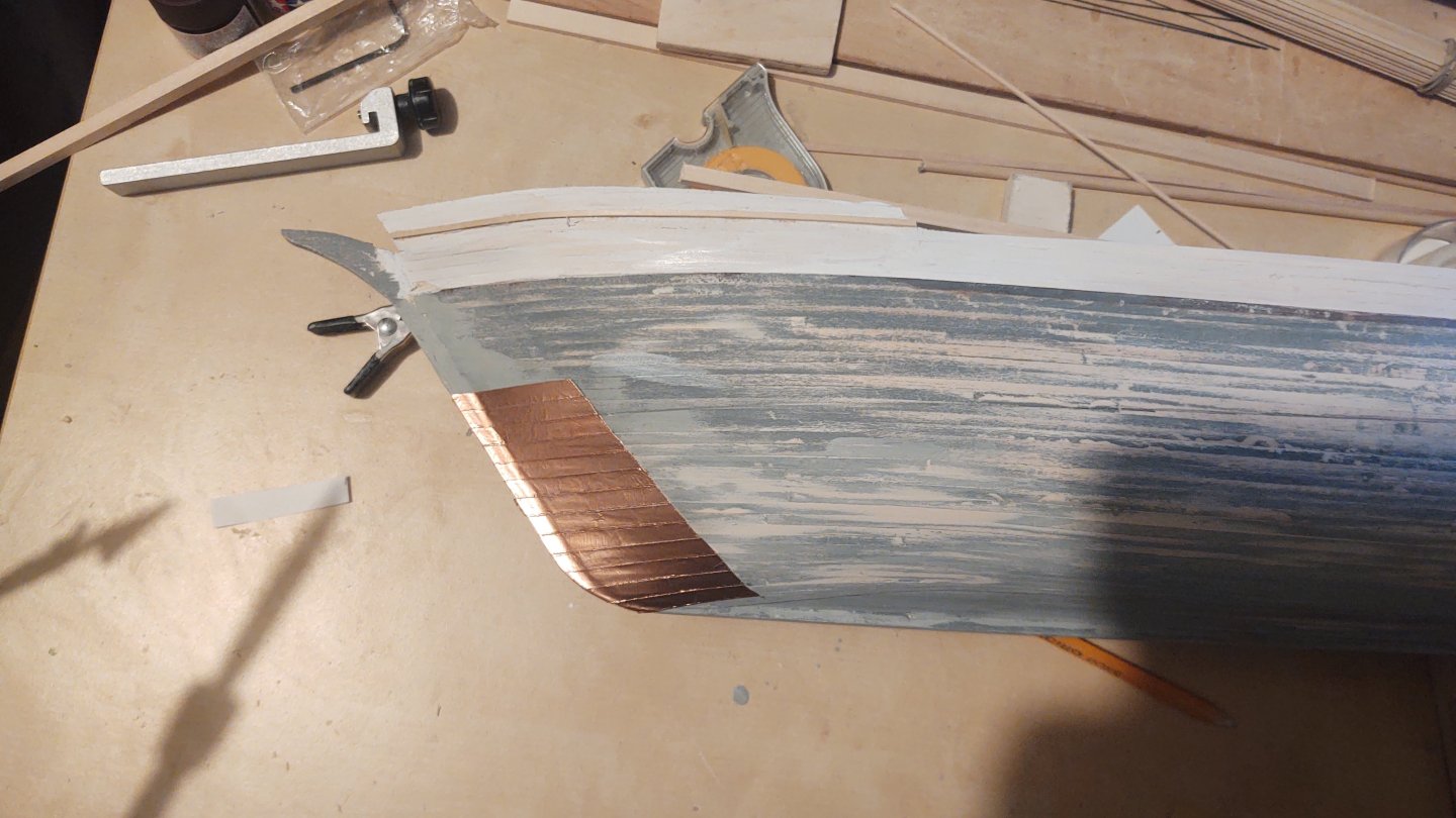
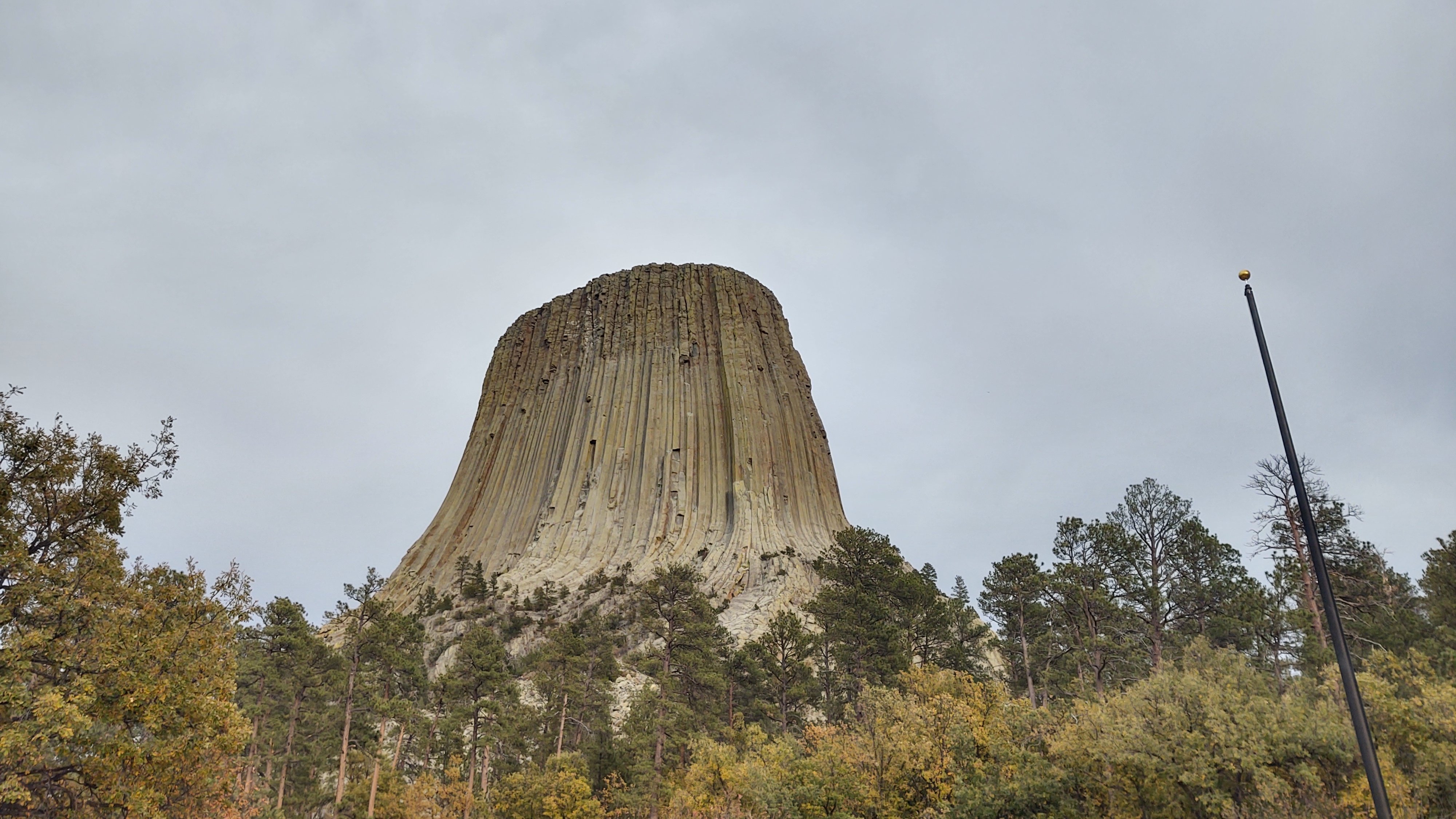
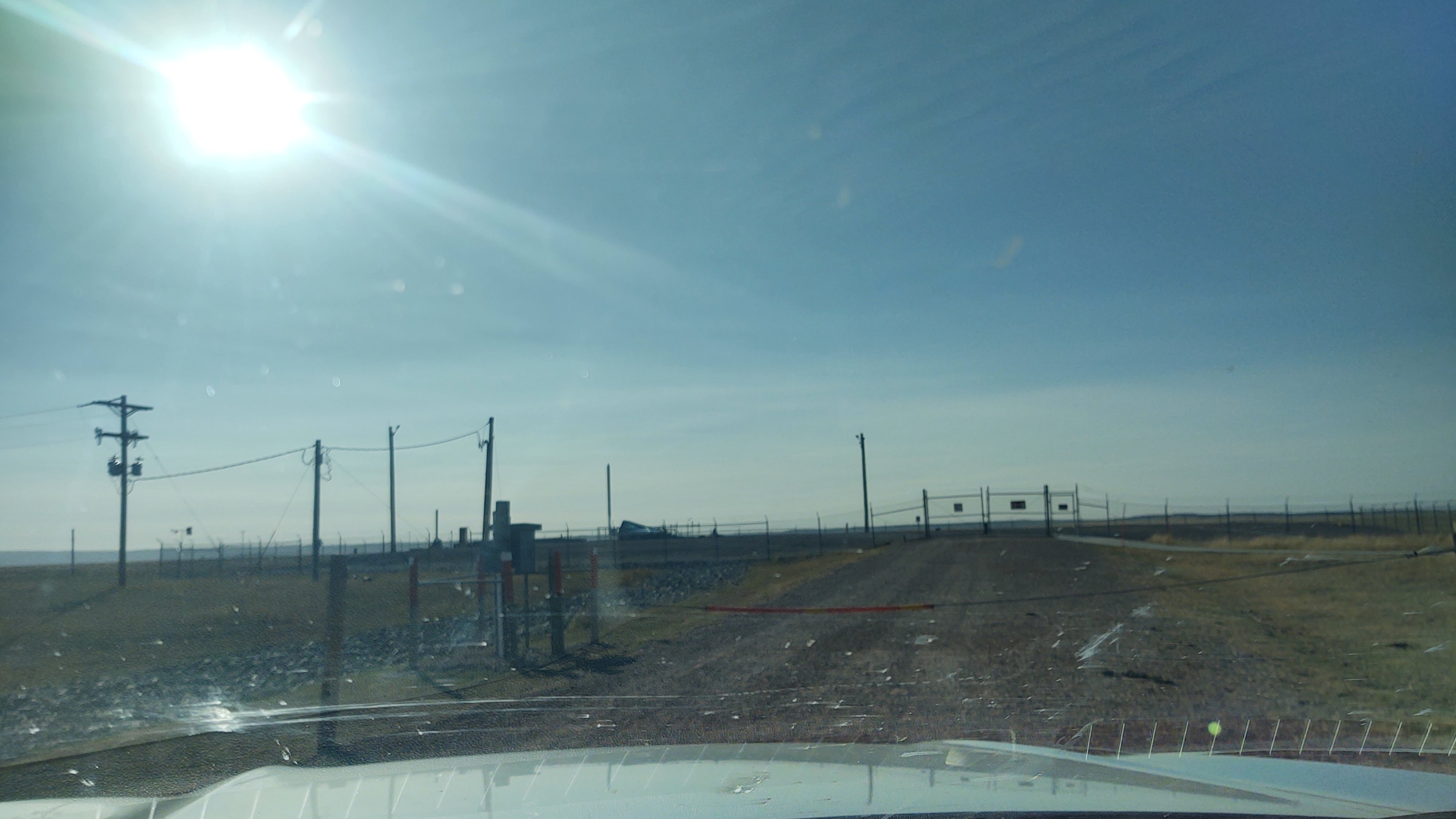
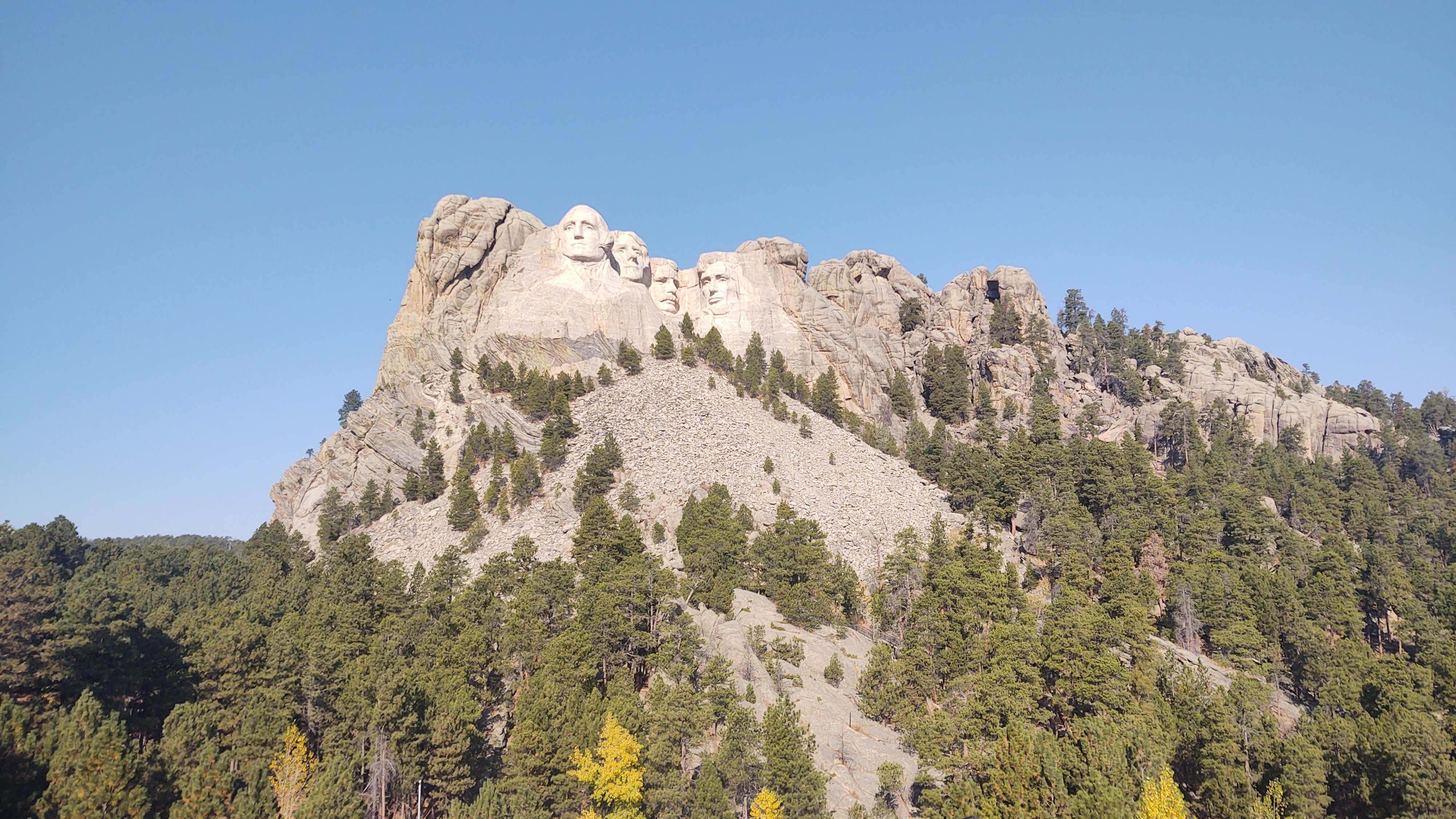
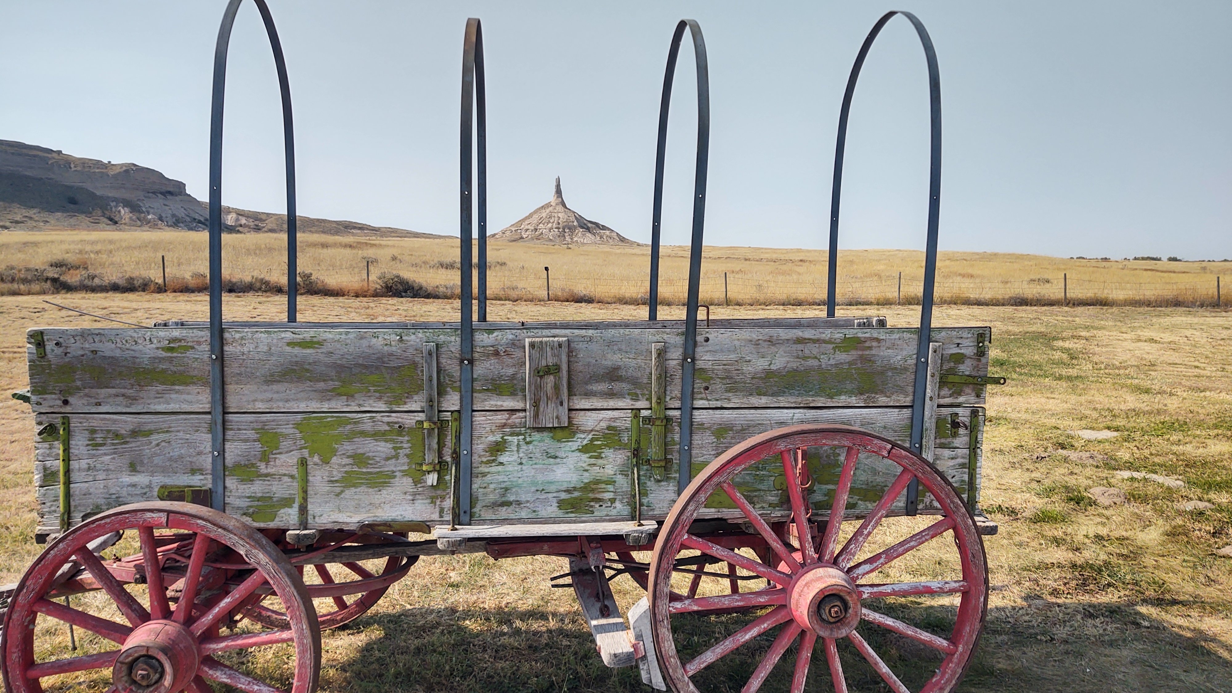
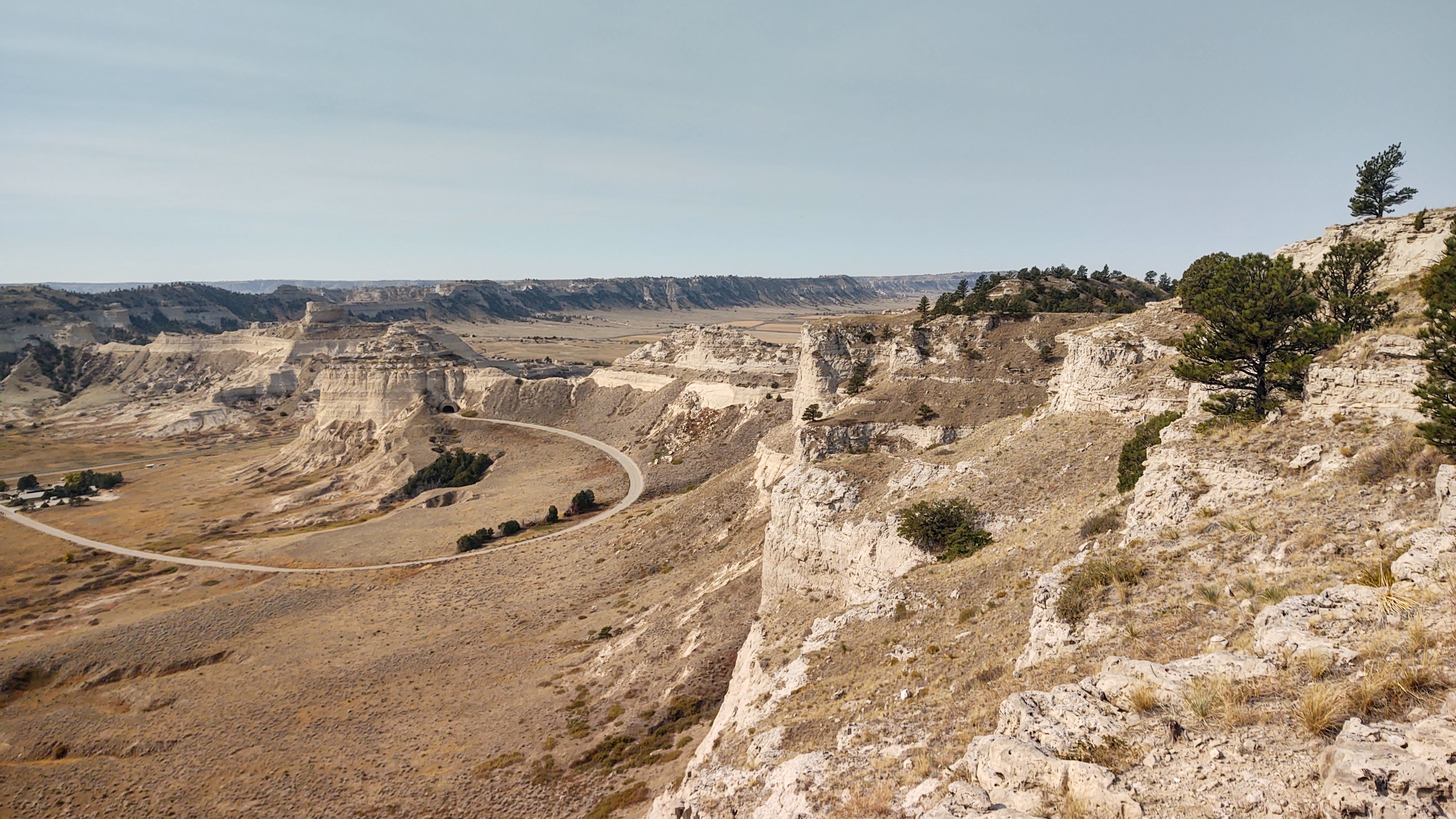
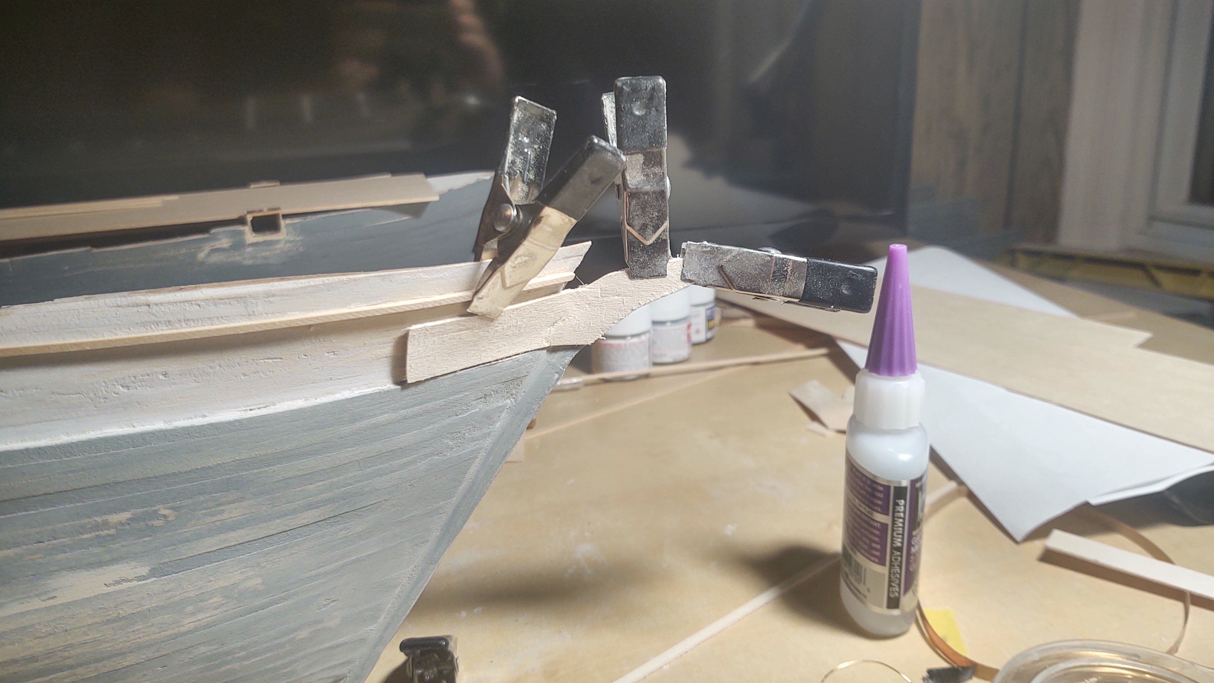
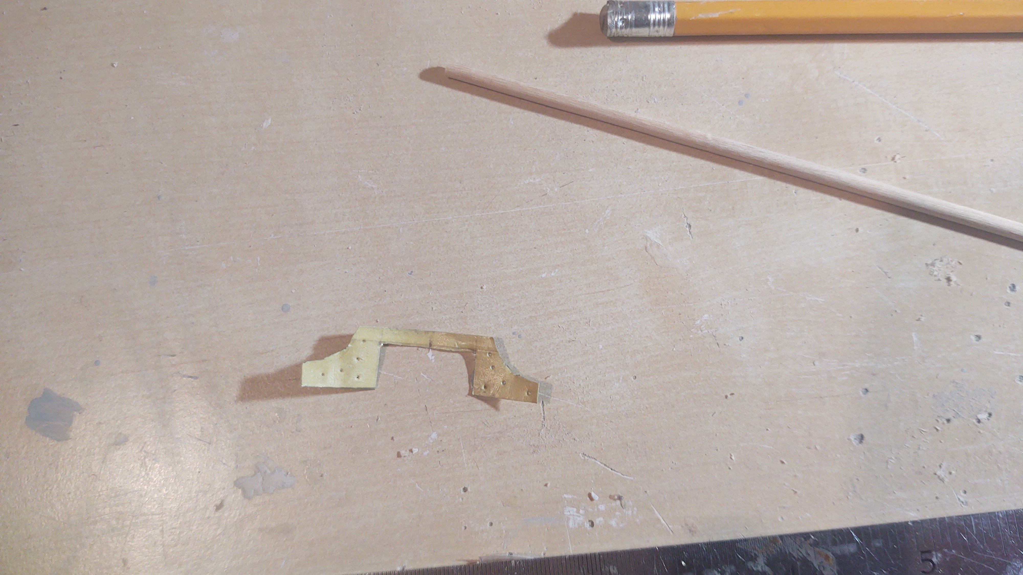
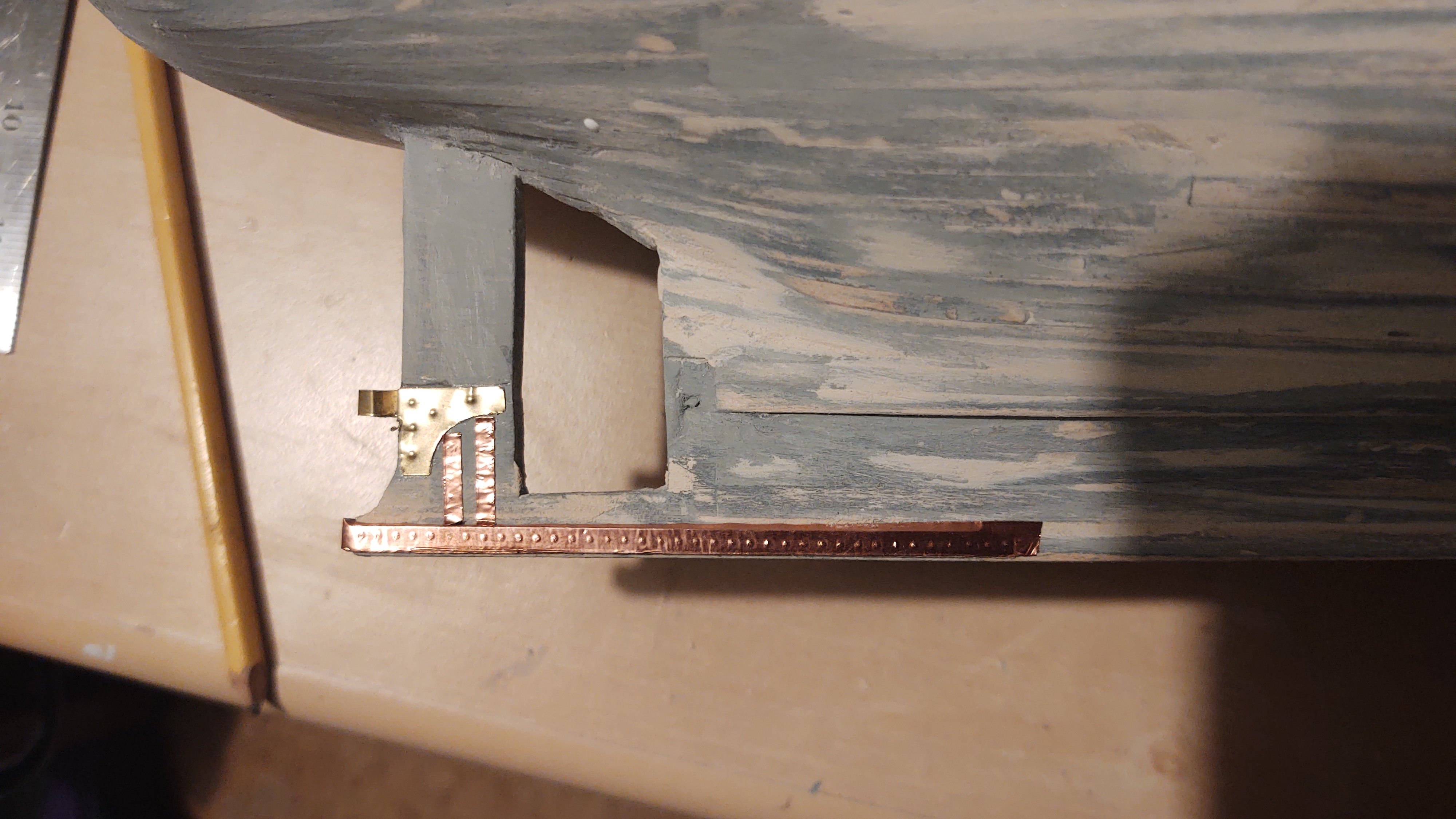
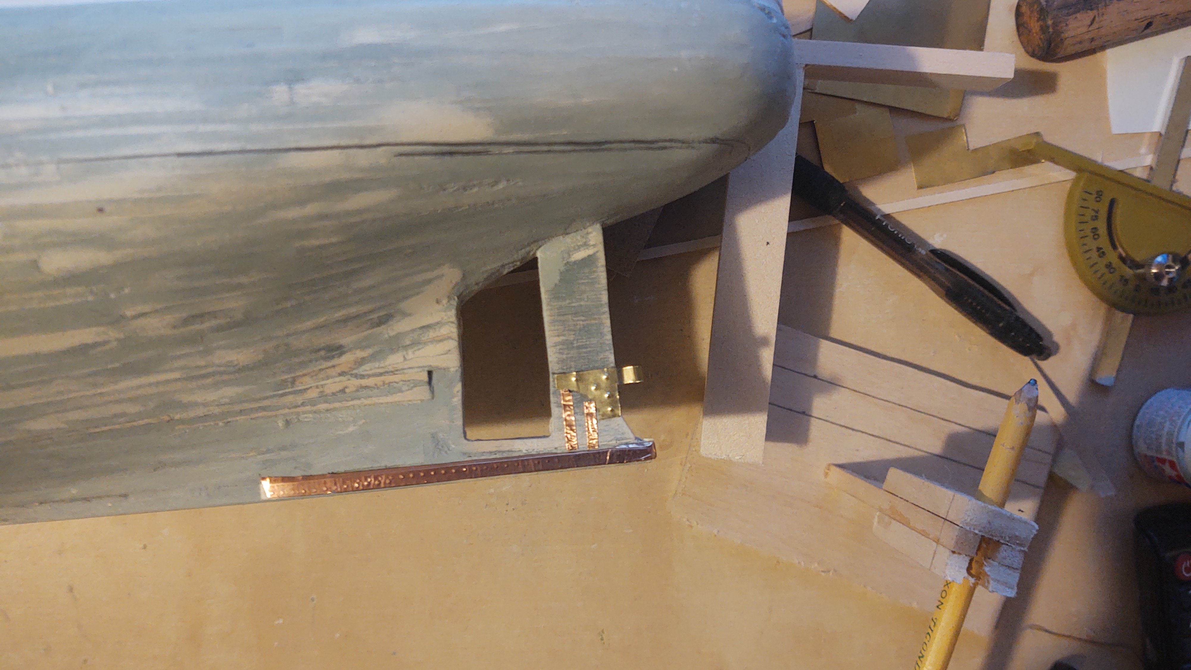
Well, finally doing an update. It's been a somewhat chaotic time for me. I'm preemptively looking for a new position, and we went on vacation with my older daughter who lives in Boise. So, good and bad, but either way reduced time in the shipyard. However, before we get there, a couple of photos from our time with our daughter in the Dakotas. We met her in Denver and drove to Rapid City and stopped a bit on the way. So, first, in Nebraska (where she lived before she moved to Boise, but never saw these sights. Scott's Bluff National Monument: Chimney Rock National Historic Site: Into the Black Hills of South Dakota, we have a number of sites. Mount Rushmore National Memorial: Wind Cave National Park. Unfortunately, the cave was closed, but the park has amazing hiking: and all kinds of interesting wildlife including prairie dog towns and these: Badlands National Park where we saw Bighorn Sheep and rugged country: Devil's Tower in eastern Wyoming: FYI - on a nautical theme, this is an old photo, but you see it everywhere in Wyoming: Finally, one additional stop, Minuteman Missile National Historical Site. We stopped at the Visitors Center but for some reason they had closed the actual missile site that day. Nevertheless, here is the Delta-9 site. One thing I have never been able to explain to my children (who are 26 and 24) is the existential dread that we all had during the Cold War. As I've mentioned in one of my other build logs, I remember the Destroyer I was on being shadowed by a Krivak in the Med off the coast of Lebanon in 1984, the Able Archer 83 fallout, and when I was in Kyiv in 2008, it was really weird to go visit the Mother Ukraine statue (then called the Rodina Mat) and see something similar to this in the form of an R12 MRBM. I certainly never expected to get this close to a (decommissioned) missile silo in my younger days. I wonder if I might have been able to provide a bit more context to my daughter if she had been able to see the missile in situ (it's visible through a glass cupola you can see in the center of the photo so that its decommissioned status can be verified by satellite) but this was the best we could do. On to the model. I've sanded the hull to where it is now ready to start accepting some of the additional components that are needed prior to painting it for real. This is the first version of the lower mount for the rudder (I realized the join piece in the middle is in the wrong place and remade it, but it gives you the idea for what I'm doing. The two roughly triangular pieces mount on the stern post, and the connector is used to create a circular mounting point for the bottom of the rudder 1/8 of an inch in diameter, with a doubled connection of 1/16 inch, with the rest of the connector (the two, 1/8 inch segments closest to the triangular elements mounted on the back of the keel. If that sounds a bit weird, here it is in situ, you can see where the loop is made and the connector is. In addition, I used a ponce wheel on some copper tape to mark some additional ironwork that is on the keel and the sternpost. Discovery has iron plates on the bow to aid in the breaking of ice. These are being made from copper tape to keep them from getting too far out of scale. I'm looking for some very tiny nails to use on the tape to represent the relatively small number of bolts. I'll see what I can find - if I can't find small enough ones I'll leave them off - they won't be very visible once they are painted anyway. The iron shield extends slightly above the load water line, which is now marked on the hull (you can see it as a pencil line). In fact, I used the LWL to direct the placement of the copper tape representing the plates. You will also see that I have installed some (unpainted) wood that represents the continuation of the main rail once it reaches the forecastle. Finally, I pre-bent and did the initial trim on the trailboards (I hope I've got the right terminology here, please correct me if I'm wrong). They will contain the scrollwork on the stem and will not go on until after the hull is painted, but I wanted to shape them first. My plan is to practice carving the scroll work on scrap until I'm confident enough to do the job and then work on the shaped pieces, but here they are for now. Initial piece (soaked in hot water and allowed to dry on the model. And with the initial trimming. I think I need to trim the area that currently overlaps the prow - need to check back with the plans. Pardon the long and rambling post. As always, thanks for looking in! Regards, George


-
For what it's worth, being in a small boat in the California coastal zone is one of only two times I've been seasick, and I've ridden ferries to the Arran Islands in gales, and been through a storm with 75 mph winds and 40 foot seas during our honeymoon (off the coast of Alaska in the old 1950s SS Rotterdam) without difficulty. The combination of (a) small boat, (b) slow, rolling chop, and (c) the fog that rolls in during the morning makes you completely lose the horizon and your senses don't know what to think. The other time was in an absurdly overheated ferry heading out into the arctic ocean. I stayed on deck for the return - rather be cold than seasick. The Cape is looking great. It's nice to see the less loved ships get some attention. Regards, George
- 492 replies
-
- 2
-
-
- minesweeper
- Cape
- (and 1 more)
-
I put the tackles in place before the fife rails, and it helped sort of. One thing I found is that if I did that and didn't bring the blocks to the approximately correct distance apart ahead of time, when I did arrange the blocks correctly, the "embedded twist" (sorry can't think of anything else) in the lines caused the blocks to kind of torsion (basically they started twisting relative to each other). Some I could untwist, others I had to do what you describe - pull it out, re-rig, and then reinstall the bolt. One more thing to watch out for is if you bump into the yard, it can pull the bolt out or stretch anything stretchable and you wind up with a "saggy" line. Needless to say, I know this because I did it many times.
- 431 replies
-
- 1
-
-
- Flying Fish
- Model Shipways
- (and 2 more)
-
Getting the first running rigging going calls for the good stuff. I personally would go for Highland Park 18, or Balvenie Doublewood, but your mileage may vary... Cheers! George
- 431 replies
-
- 1
-
-
- Flying Fish
- Model Shipways
- (and 2 more)
-
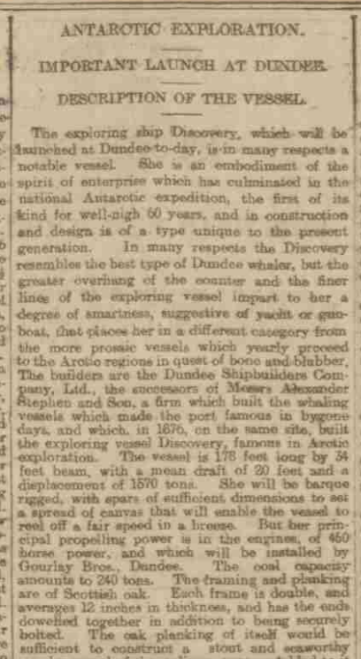
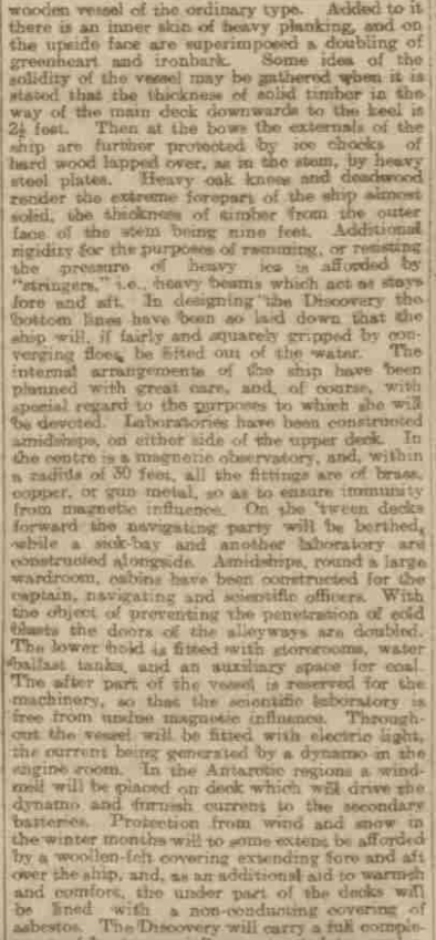
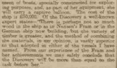
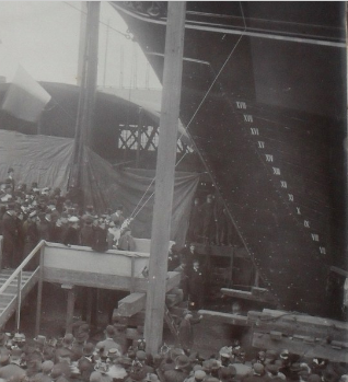
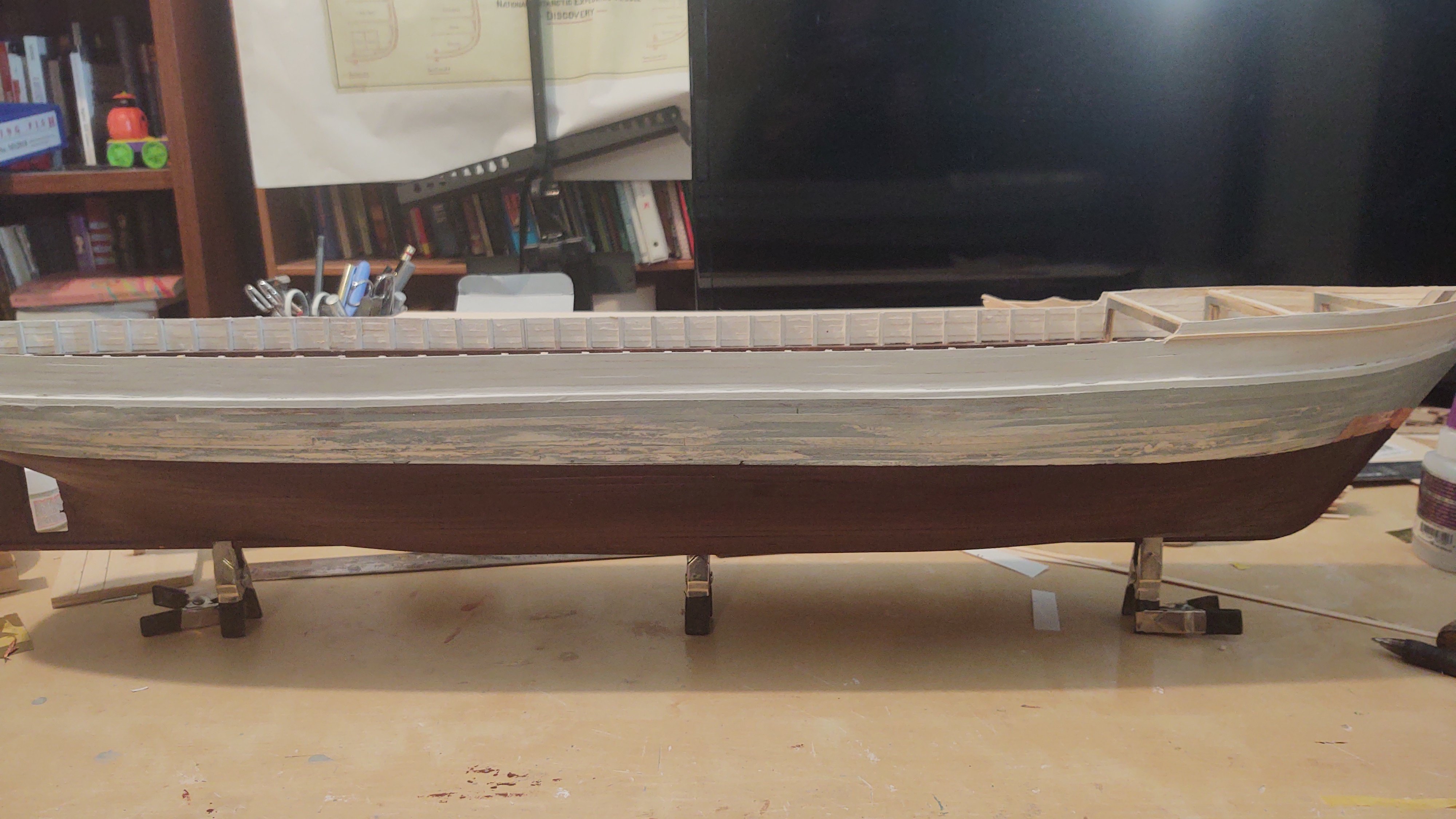
Well, another update. First the ship. The bulwarks are done, as are the bulwarks that enclose the forecastle. Two images. The first image is after the first sanding of the primered hull. As you might expect it's pretty ugly as it removes the primer on the 'high' parts of the hull: After sanding and with a second coat of primer: The second coat of primer looks much better than the first at application. There are still areas that need some filler, and sanding, but it's definitely starting to shape up. BTW, I painted the bulwarks white on the outside to seal any gaps where leakage won't damage the inside. Hopefully when I put the black on the bulwarks it will stay on the outside where it belongs. As to the colors. I've been doing additional research, but haven't found anything definitive yet. Via the British Newspaper Archive, we find the following report from the Dundee Evening Post on 21 March 1901: ANTARCTIC SHIP DISCOVERY. LAUNCH THIS AFTERNOON. A large assemblage of spectators was present iu Panmure Shipyard this afternoon [to] witness the launch of the exploration vessel Discovery. The building of this interesting craft has occupied little over a year, the first section the keei having been laid in the early days of M-irch last year. It is expected that the rigging and fitting out operations will occupy the best part of six weeks, and she will then proceed London for stores. Several members of the expedition party reached Dundee yesterday, aud, indeed, Professor Gregory, of Melbourne University, was the principal absentee. Invitations were issued to the following Sir Clements R. and Lady Markham; Sir Reginald Ogilvy, Bart.; Sir James Low Lady Low; Mr and Mrs G. W. Baxter; W. Thomson; Mr I. J. Weinberg; the Hon. J. C. Higgins, TJ.S. Consul; Mr E. Maitland; Mr and Mrs W. H. Fergusscn; Mr and Mrs W. Low; Colonel Cautlev, R.E.; Colonel Baillie; Captain R. F. Scott.. K.N., commander of expedition, and Mrs Scott; Lieutenant Armitage, R.N.R.; Lieutenant Royds, R.N., Mrs Rovds and Misses Royds; Mr R. She! ton, R.N.; Keltic; Dr Koettlitz (scientific staff; and Mrs Koettlitz; Mr George Murray, British Museum (Professor Gregory's deputy); Mr C. Longhurst, secretary National Antarctic Expedition; Mr H. W. Smyth, London; Dr Hill (scientific staff); Mr R. Paterson, manager, Panmure Shipyard, and Mrs Paterson; Mr G. E. Kidd. secretary, Dundee Shipbuilders' Company, Limited, and Mrs Kidd; Bailie Barrie; Treasurer Ritchie; Lord Dean of Guild Bell; Captain Wilson Barker, R.N.R.; Captain Montgomery, R.E.; Commander Austin, R.N.; Surgeon Brown, R.N.; Captain Abbot Anderson; Professor D'Arcy Thompson; Dr and Mrs Bruce, Edinburgh; Mr A. Leitch and Miss Leitch, Dundee; Mr and Mrs R. Leitch: Mr and Mrs Rettis; Mr Thomas Winton; Air John and Miss Henderson; Mr and Mrs Wilson; Mr and Mrs J. P. Newton; Mr H. G. Gourlav, Mr Charles Gourlay, and Mr J. G. Lyon (Gourlay Brothers & Co.); Mr Grant Barclay (Caledon Shipbuilding and Engineering Co.. Ltd.); Mr William Morrison and Mr Howie, Lloyds' Surveyors; Mr A. Watt, Board Trade .Surveyor; Mr F. Stephen; Mr F. W. Emmet; Mr Bartholomew, Edinburgh; Mr Stuart Gray, Kuitauns; David Bruce, Loudon; Mr I). Wyllie, Dundee; Mr B. L. Nairn; Mr William Kinnear; Mr R. V. Scroggie; Mr James Mitchell, and the local whaling captains. DECORATIONS AT THE HARBOUR. In honour of the occasion bunting was plentifully displayed at the harbour. The whalers, needless to say, were prominent in their decorations. Every vessel had a streamer of bunting to the mast-head, and an appropriate touch was to be seen in the case of the North Pole vessel America, where the Stars and Stripes floated alongside the Union Jack, the mission of the America compared with that of the Discovery being literally "wide as the Poles asunder." The flagstaff's at the dockgates were also gaily bedecked, the whole going to make up a bright and animated picture. THE LAUNCHING CEREMONY. For the purposes of the launch huge staging was erected close the stem of the vessel, and to accommodate the launching party a platform about ten feet square had been erected a few feet in front. A barricade had also been placed about ten feet from the side the vessel to keep back the spectators, and prevent them hampering the workmen in the discharge o[f] their duties. The attendance of spectators was unusually large, and it is estimated that the time of the launch there were about 3000 people congregated within the Panmure Yard. They began to gather shortly after one o'clock, and little after two nearly every position from which a view of the approaching launch could be obtained was occupied. At the Marine Parade the crowd was especially dense, and great difficulty prevailed in keeping them in order. SHE'S OFF. By three o'clock everything was in readiness. The gangway leading to the ship was cast on, and thos[e] who were booked for the " maiden vo[y]age" the Discovery gathered on the forecastle, and from their high perch watched the preparations for the christening. The launching party appeared about, quarter-past three. Sir Clements Markham, Lady Markham, and the other distinguished guests being the centre of .attention. The party having taken their position, Mr Paterson, after seeing everything was in readiness, gave the older to the men who were in waiting with hammers in hand. A brisk hammering then took place, and the shores supporting the vessel tumbled to the ground. A slight pause was then made, during which Lady Markham let go the bottle of wine, which, encased in a bouquet tied with the tri-coloured ribbon, was swung cords from the forecastle of the Discovery. The bottle struck the bows, but, to the surprise of the spectators, who expected to see the vessel glide away, she remained fast. It then transpired that the easing operations had not been completed. A minute two of tension followed. More brisk hammering then took place, and the cry broke forth —" There she goes." The vessel, indeed, had begun to move. Gaining speed, she rushed on and with terrific splash the Discovery took the water. The tugs Renown and Excelsior were in waiting, and at once took her in tow. She was berthed in Victoria Dock, where she will be engined. A luncheon was held late in the afternoon. AN IMPORTANT LETTER. The following letter has been received from W. E. Smith, chief constructor for the Admiralty, a gentleman who designed the Discovery:— The building of the Discovery is unique a character that much more than the usual interest attaches to her. Usually when vessel is required to built there no difficulty obtaining tenders from large [nu]mber[s] of competent firms, any one of which might safely entrusted with the work. The Discovery, however, [is] of [n]o usual character, either as regards the material of her construction or regards her design. A large number firms were invited tender, but the tender from the Dundee Shipbuilders Company was the only one that indicated any real determination to grapple with the difficulties and novelty of her design if opportunity were afforded. It might perhaps have been anticipated from the past history and experience of the firm that they would not flinch from the difficulties of the case, but the fact remains that stood foremost in the breach and undertook to build the without, which the [e]xpedition could not be undertaken. The firm having accepted the responsibilities involved the building of the vessel, once set. work in the actual construction of the ship, and have vigorously and continuously prosecuted that work ever since, and have endeavoured their part nothing undone that could contribute the seaworthiness of the vessel or the comfort and convenience of those board: and there firm in the country having greater knowledge of what, necessary in the[s]e particulars for this type vessel than the Dundee Shipbuilders Company. In the interests of the expedition [I] have, [I] am afraid, been sometimes exacting, but I [am] most pleased to say that have been very handsomely met, and my work has pleasant one. desire particularly thank Mr for the very great interest he. has taken the work and the skill in which has executed it. I am much indebted to him for many useful suggestions, the adoption of which will make the ship more efficient than she otherwise would have been. I [am an] old wooden shipbuilder my[s]elf, and I must congratulate the firm on having in their [ser]vice yard foreman the qualifications of Mr John Smith, who has, under Mr Paterson's directions, so thoroughly attended the actual work of building. I hope w[e] live to s[e]e another Discovery launched, and that the Dundee Shipbuilders Company will again ready undertake the work they have [ris]en [to] the occasion. Nothing about the color of the ship unfortunately. Similarly from the Aberdeen Journal (same day): Again, nothing about the color. [As an aside, the article mentions, and I've seen photos, that she carries a balloon. I was going to model the gas tanks (stored above one of the after deck houses, but a tethered balloon might be more interesting yet.] However, I have concluded that there must have been some different color up to the top Plimsol line. Here is another photo with an apparent color change. The most common colors were red and green. It has to be something that doesn't use iron oxide based pigments, so that suggests either red lead (which apparently uses lead II|IV oxide as a pigment, or verdigris (copper II oxide), or emerald green (copper(II) acetate triarsenite or copper(II) acetoarsenite). The arsenates and copper compounds would act as antifouling agents on their own. Bottom line is that I need to make a decision, and probably pretty soon. I'm now thinking I'll make it green or red, without boot topping. Thanks for looking in and for the likes! Regards, George


-
Glad to be of service. Your Fish is really coming along great! Regards, George
-
Looking great. You are making real progress and fast! Regards, George
- 431 replies
-
- 1
-
-
- Flying Fish
- Model Shipways
- (and 2 more)
-
That could be. The ship is a bit odd in a bunch of ways because of its purpose/mission. For example, the foremast (which has the same size yards as the main) uses hemp rigging (and tied ratlines) vs. metal rigging for the main, presumably because they needed to keep iron away from the magnetic observatory which is aft of the foremast. Clearly there was iron/steel on the ship, but it would have been kept away from the observatory (supposedly the original wardroom upholstery had to be replaced with a version that didn't have metal buttons). If I understand, the primary biocides would have been copper based, but the primary source of color for red paint in those days was iron oxide. Add the copper and it changes the hue somewhat, but don't put in the red to avoid slathering the ship in iron oxide? It's an interesting problem. Regards, George PS - Picture of the foremast standing rigging:
-
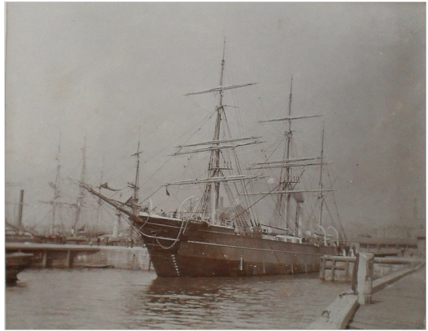
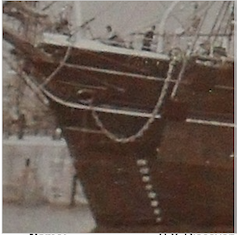
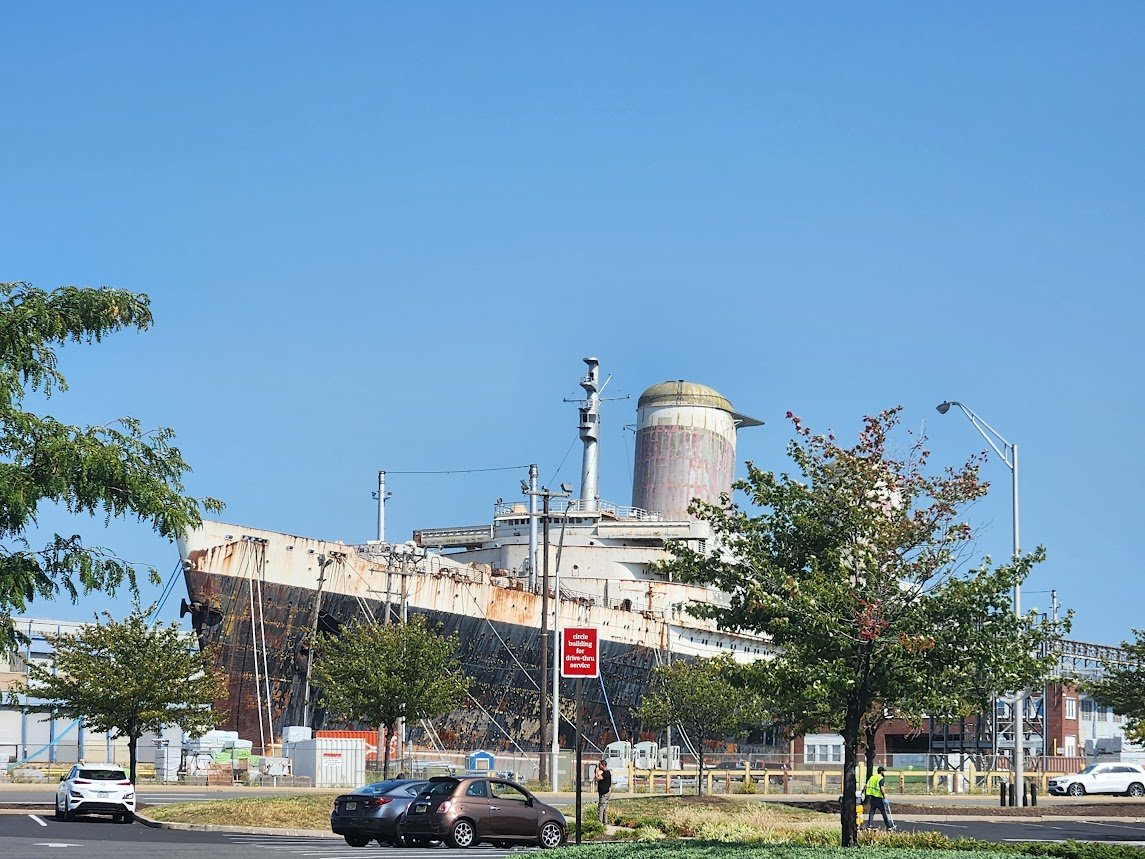
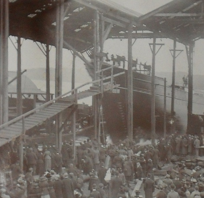
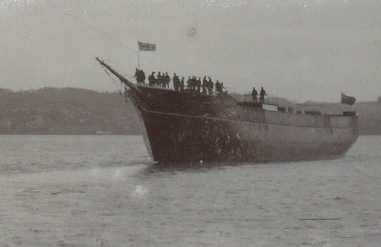
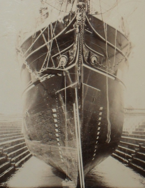
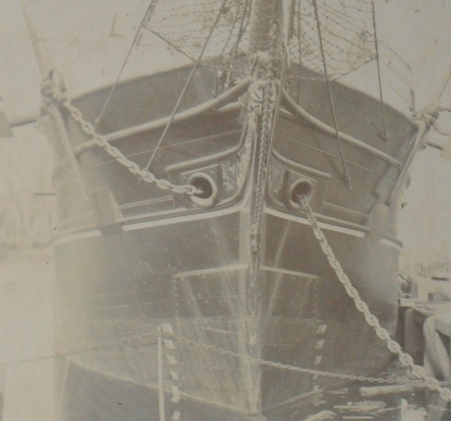
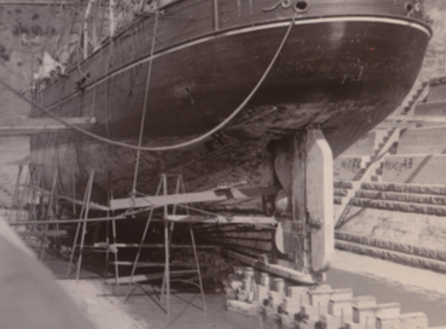
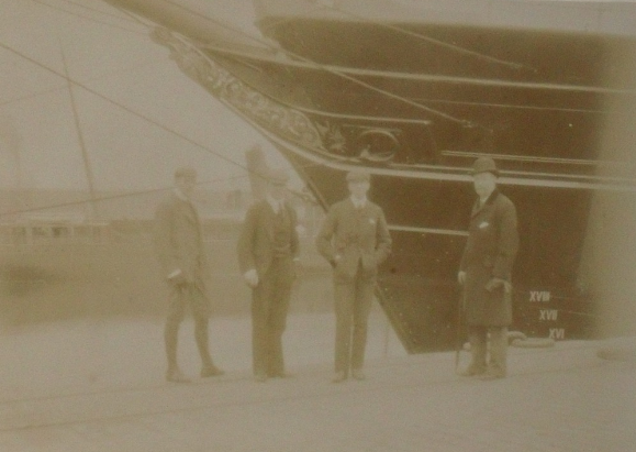
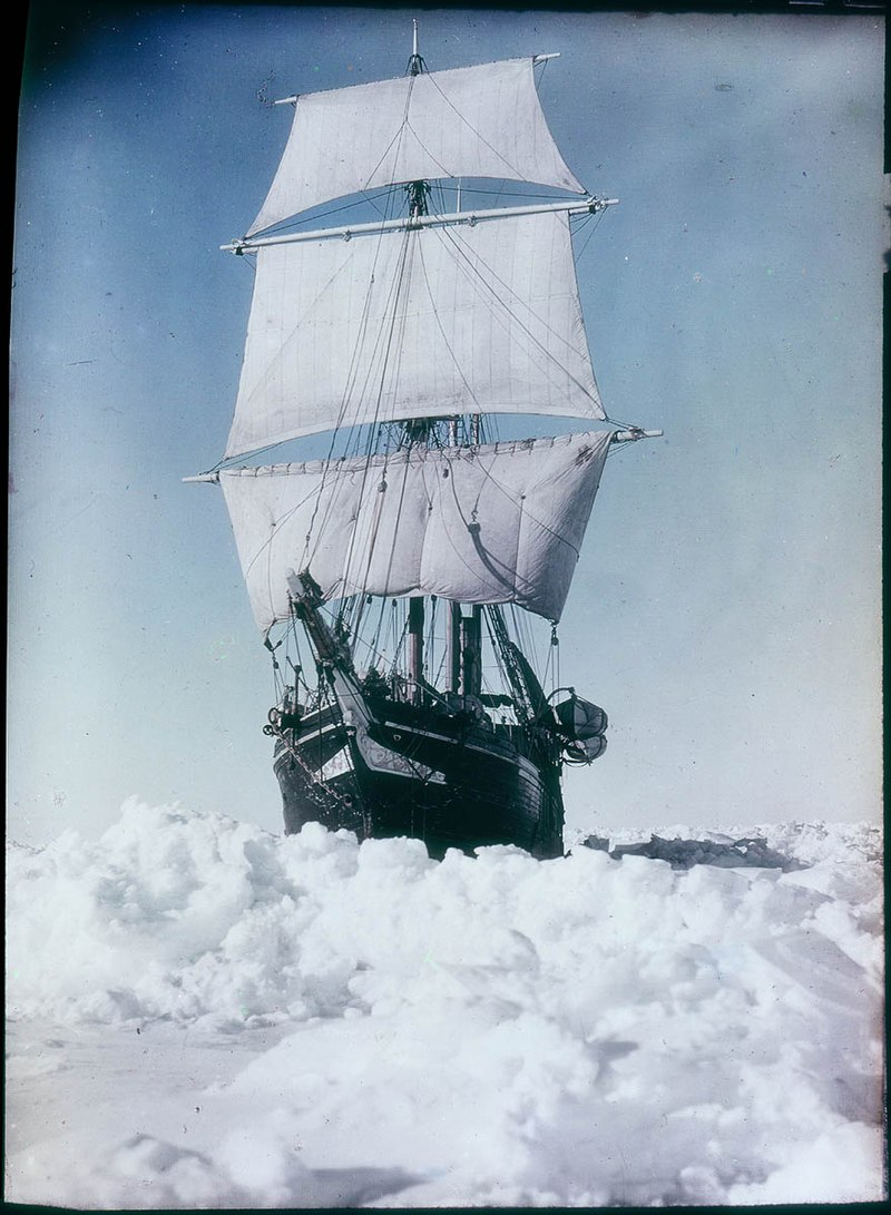
The bulwarks are continuing apace (I will put some photos up when they are completed), and that has me thinking about one of the big questions about the hull - namely, what color is it below the waterline. But first, I was in Philadelphia on Monday moving one of my kids from a horror of an apartment to a much nicer one. We went out to the Ikea on Christopher Columbus Way to buy her a small table, when I was very surprised to see the SS United States. Probably for the last time before she goes to Florida to become an artificial reef. It's sad to see her go, but off hand, I'm not sure that anyone has the money to really save her. The funny thing is that the ship seemed small, which it is not (I mean the ship is 990 feet overall with a beam of 101.5 feet, and a height of 144 feet from standard load water line to funnel. But compared even to the smaller modern cruise ships (we took a trip on the Holland America ship Konigsdam in 2017) the Big U doesn't have the same amount of bulk. I'm not complaining - her lines are fabulous, but it's still something of a surprise at the difference. Anyway, on to the color below the waterline. The historian at Discovery Cove in Dundee responded to my inquiry, but if the color was recorded, they don't know where. I've been looking for something akin to Duncan McLean's Boston Daily Atlas (there do seem to be a small number of digitized newspapers from Dundee, and perhaps someone mentioned it in a news story about the launching). The historian did however point me to a collection of construction and launching photos (https://www.dhtcollections.com/item/Brand_SYDiscoverybuildandlaunch_0_0_26347_74.html). They are, of course, black and white and more than a bit ambiguous. Here are some of the key photos (or more accurately portions of them). Launch day: Another view of launch day: In the water: When I look at these photos, I'm just not seeing any obvious indications that the bottom was anything but the same color as the rest of the hull - black. Now here are two post-launch photos of Discovery in drydock: and one from Australia: and one from Dundee: The photos from Dundee seem to show a different color at the highest Plimsol line, although the modern ship is not painted that high. The ship had (has) metal ice breaking material on the bow - could that be what is the slightly different color up to the upper Plimsol mark? As to the bow on picture in drydock - could that just be salt (or wear) with the ship running at the standard load water line? I'm starting to think that the correct color is black. And I note that Endurance appears to also be painted black below the waterline as seen in this Paget color photograph by Frank Hurley: Any thoughts welcome. Regards, George

-
Jared, the stunsail booms were moved with tackles. I've seen pictures, but can't seem to find them now - if I figure out where I'll send you snaps. Needless to say, I didn't bother including them. Regards, George
-
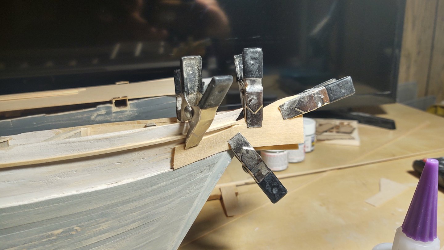
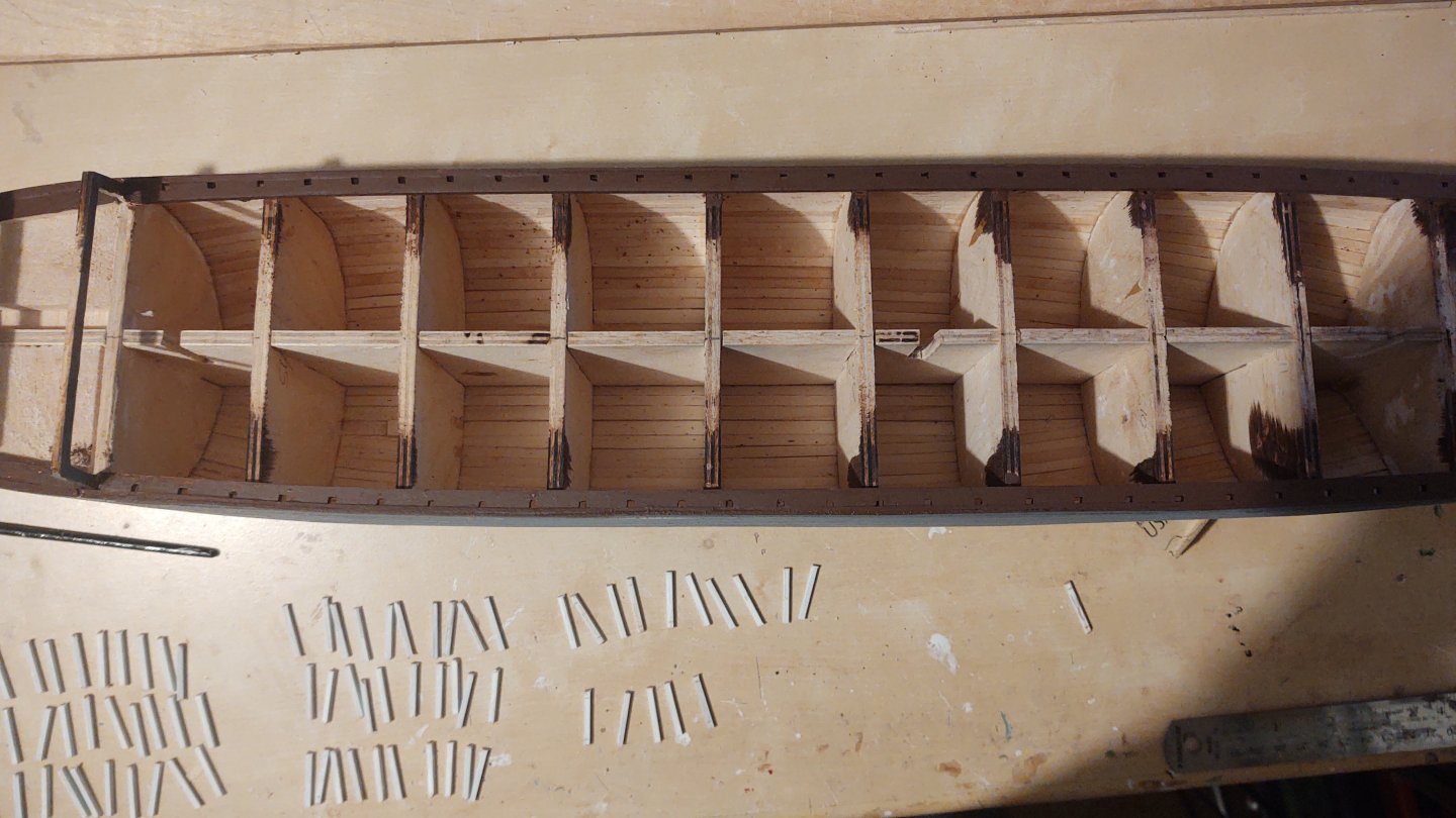
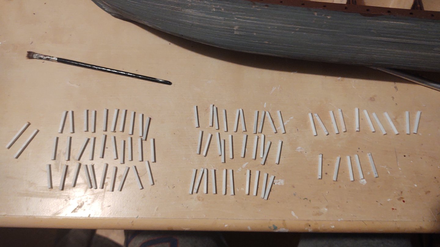
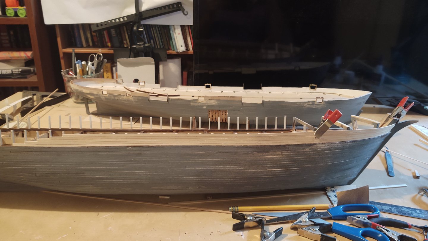
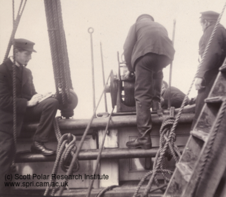
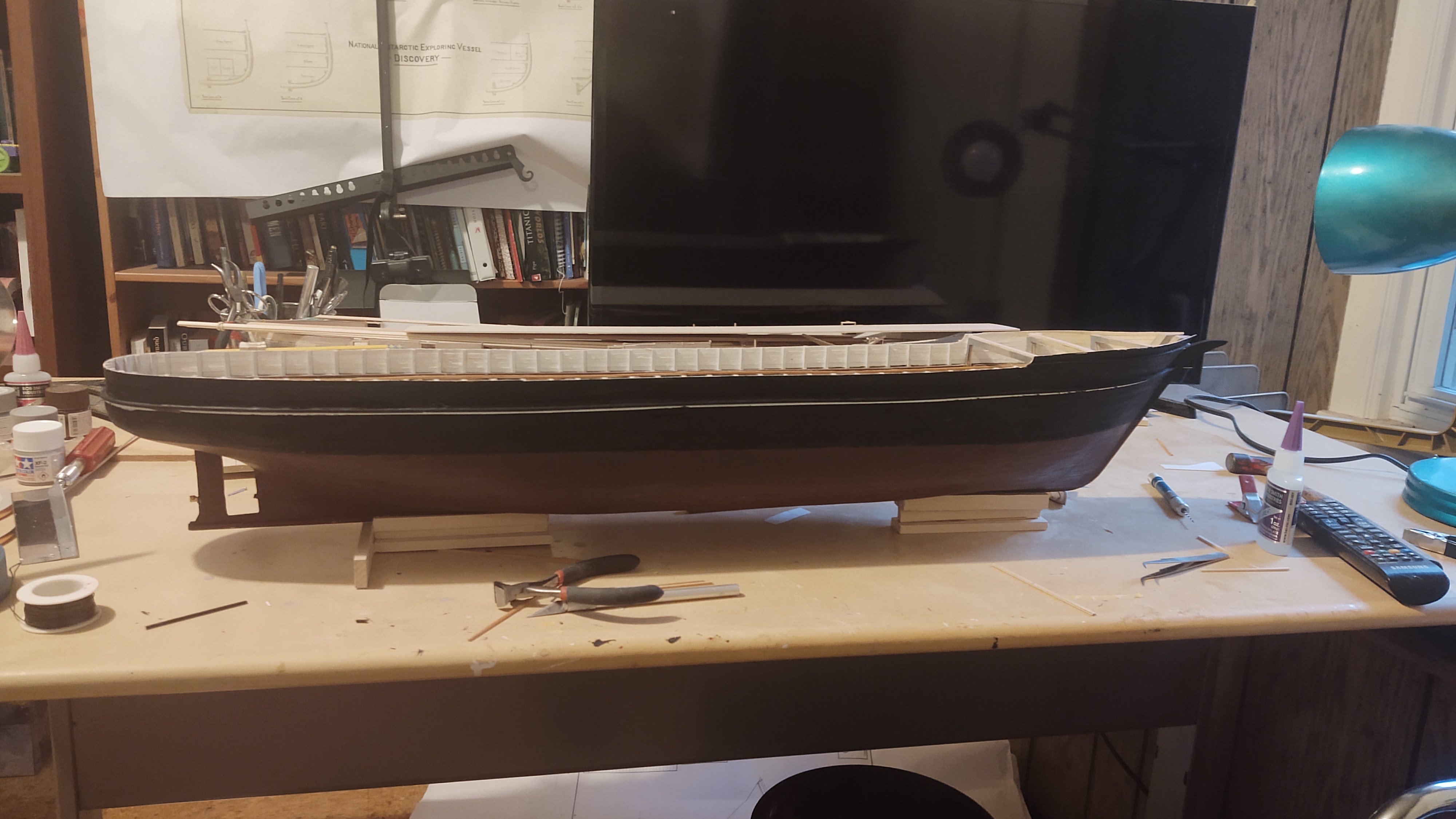
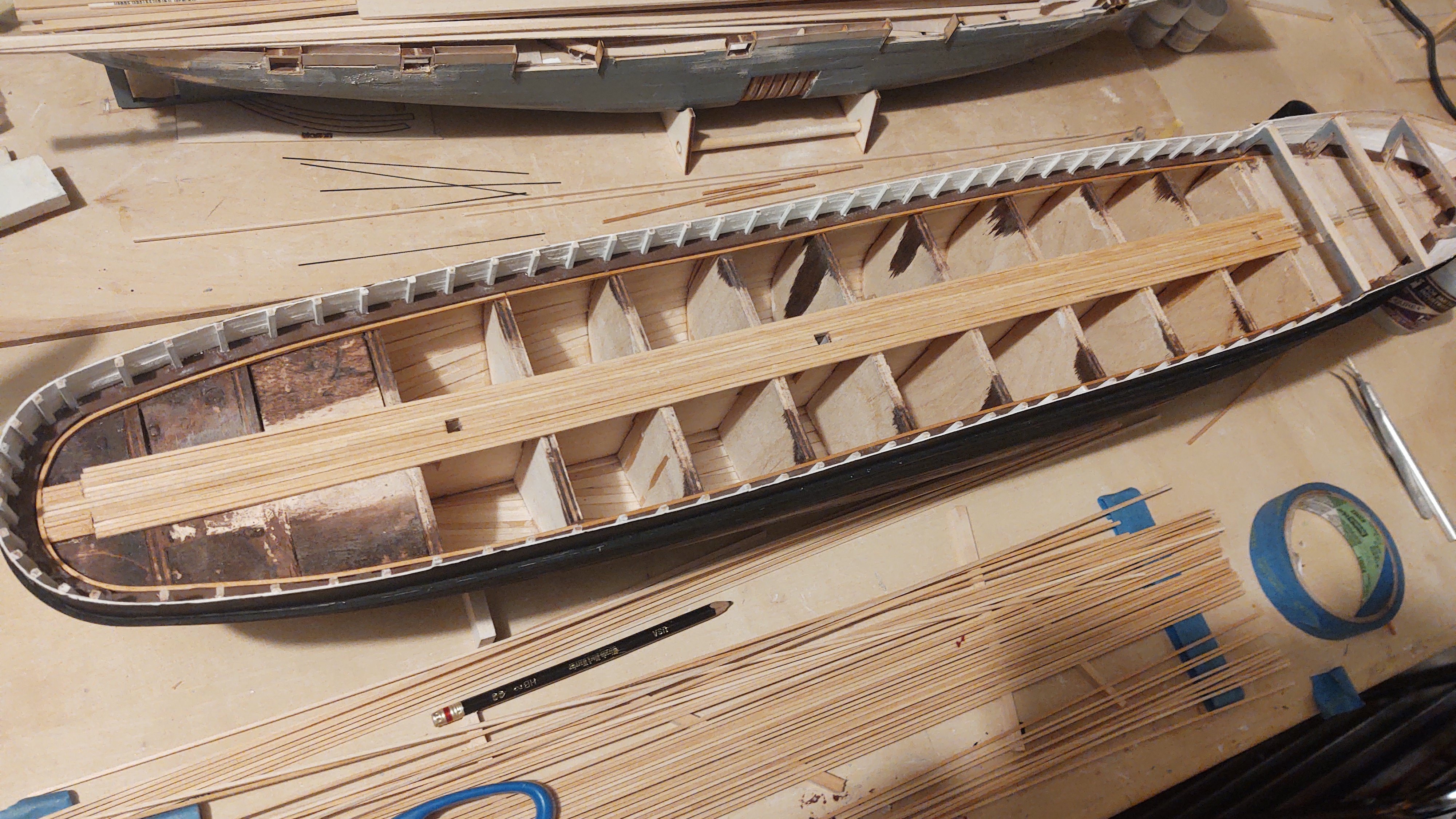
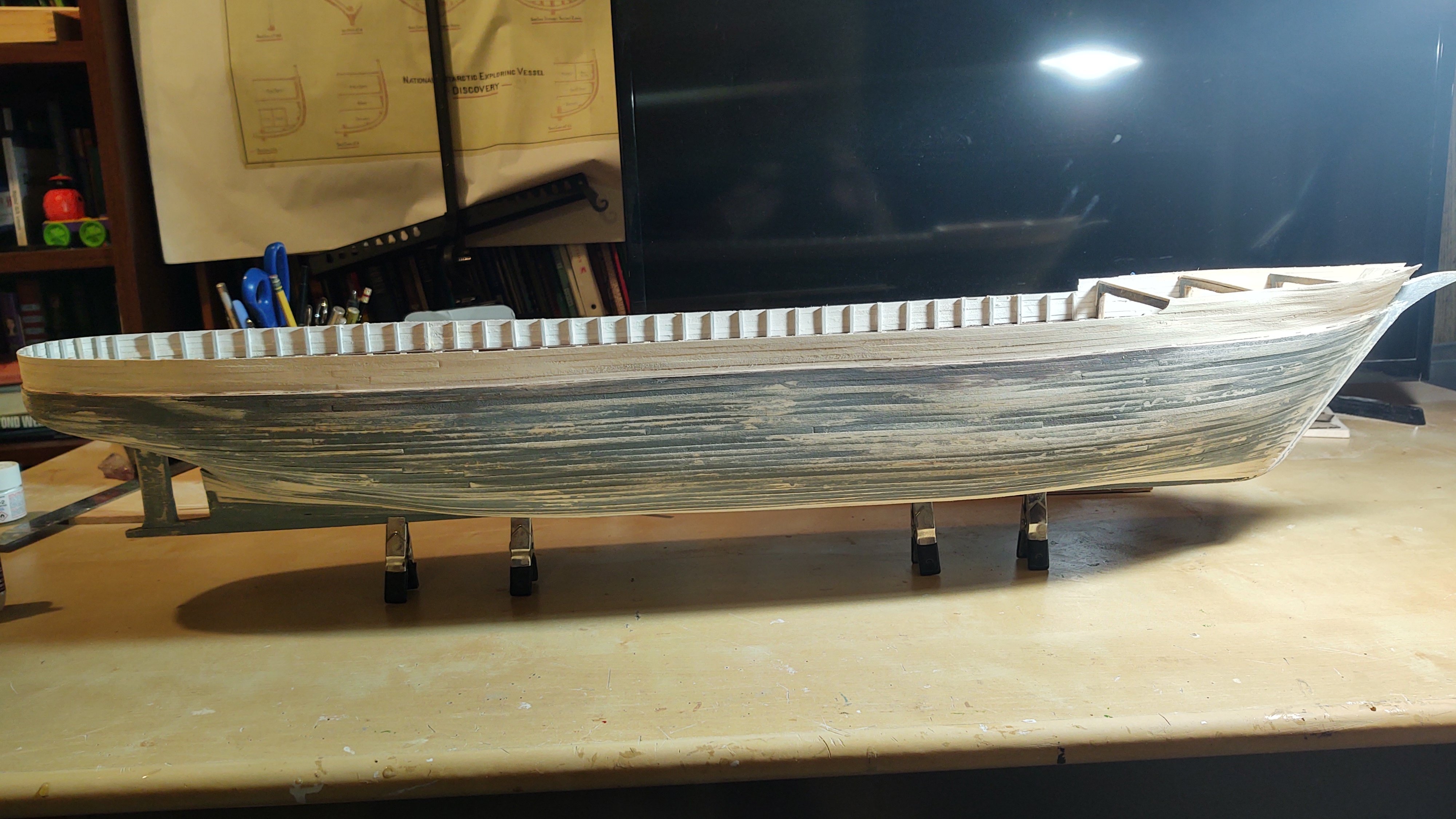
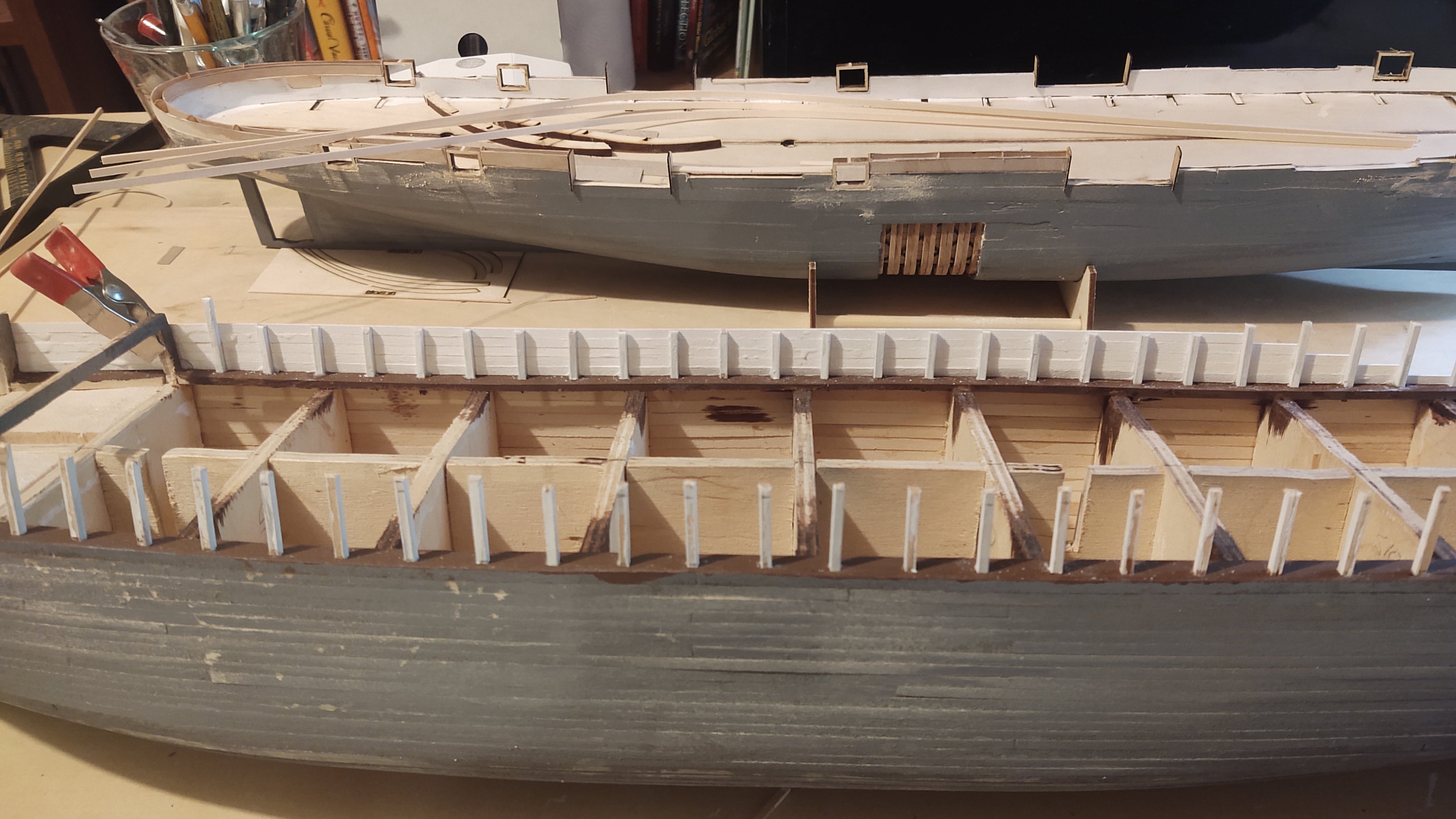
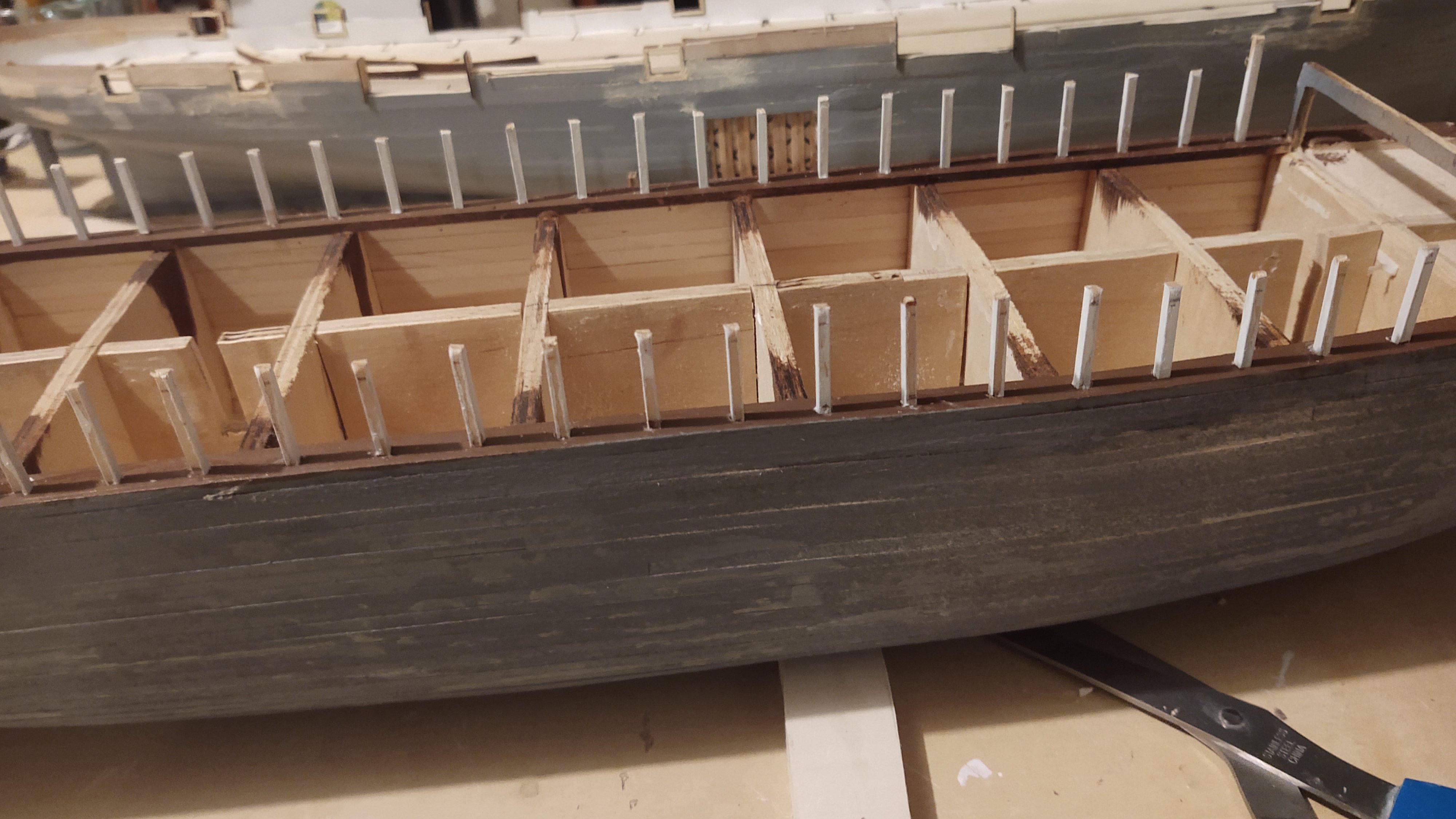
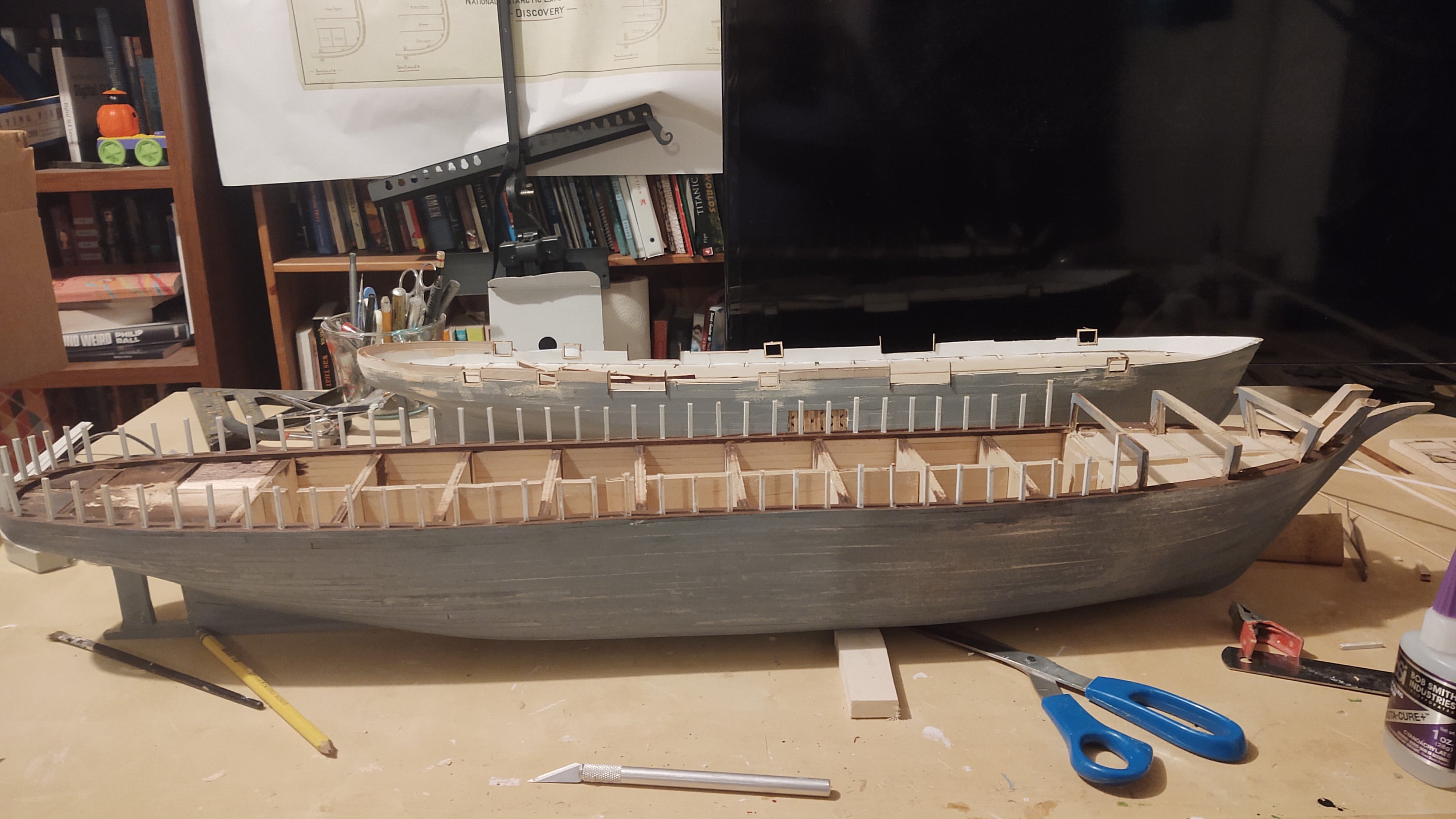
I swear that this will be the last I say on the subject of measurement. But - if you haven't seen this, it's worth the five minutes: Now back to the ship. I found some extra wood in my stash and mostly finished the hull planking, so I hit the hull with some gray primer to see just how much sanding is required. Answer is definitely some. However, I'm going to do that one time after the bulwarks are in place, so that is the next step. On the ship in 2024, the planksheer and waterways are a dark brown, as are the bulwark stanchions with white bulwarks. In 1901 it seems like the bulwark stanchions were white, with a planksheer and waterway that were the color of the rails. If you look below the lashed poles in this photo you'll see the waterway: And here is a photo of a stanchion: Given this, my inclination is to paint the planksheer, the interior of the bulwarks, and and the bulwark stanchions prior to installation and then painting the exterior of the hull. My initial thought was to stain the planksheer, but that was not a huge success. Even with pre-treating it, it was very blotchy, and I think that the problem was that I got glue on the wood during the installation of the planks. I tried sanding it a bit, but no dice. In the end, I found some paint of a similar color to the oak stain I'm going to use on the covering board, and said time to move on. Next step was to make 77 stanchions. 75 of them are 3/32 in square boxwood, painted white on 3 sides (the final side is left unpainted to adhere better), cut to a length of 1 inch, with a mark on the unpainted side 1/16" from the bottom, and 2 are just 1/2 inch longer. Similarly, I took 1/32 by 1/8 basswood strips, and painted one side white; these would be the bulwarks. I then installed them into the pre-cut holes in the planksheer. Most of Discovery's bulwarks are pretty vertical - I made a little jig to help with the locations that are not. This yielded an arrangement like so: I then started mounting the basswood strips, using the stanchions to define the curve of the bulwark. Once I reached the height that I was aiming for (in this case 5/8" or 45 inches at scale, I clipped off the top of the stanchion. Here it is from the outside. And from the inside: Once the bulwarks are done, and the hull sanded, I can mask off the bulwark tops and paint the outside. And this way, I don't have a lot of spillage of the bulwark planks on the planksheer. Anyways, I think in a couple of weeks, I will be able to paint the exterior and it will start looking more like a proper vessel. As always, thanks for looking in. Regards, George


.thumb.jpg.1f40727f9fc34c0fd0957de40c6eaa3c.jpg)
-
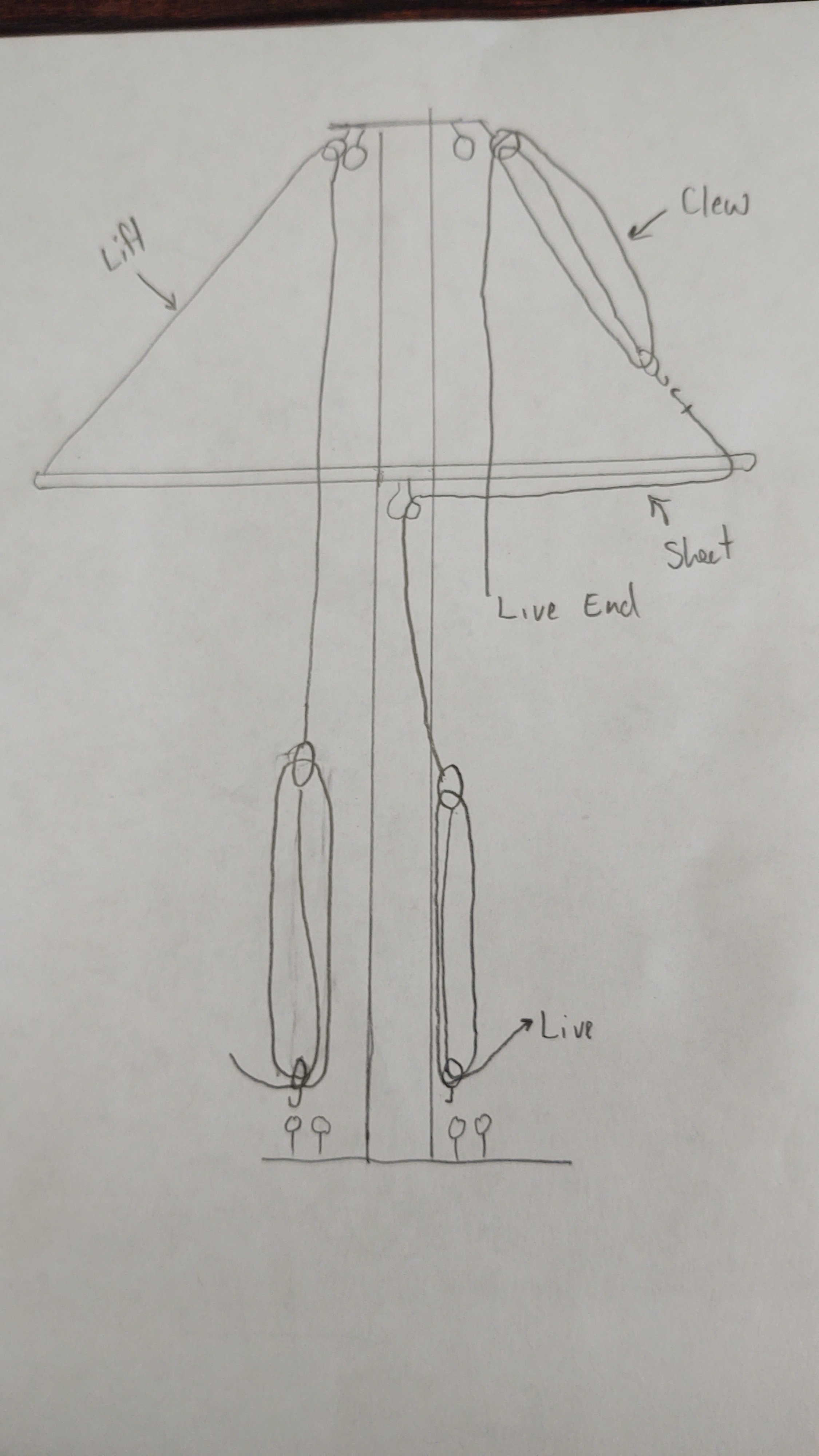
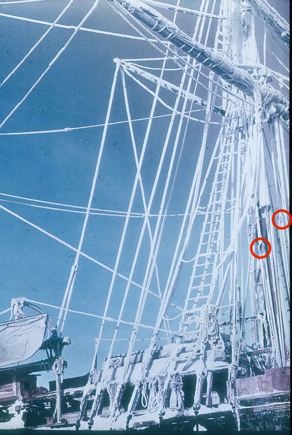
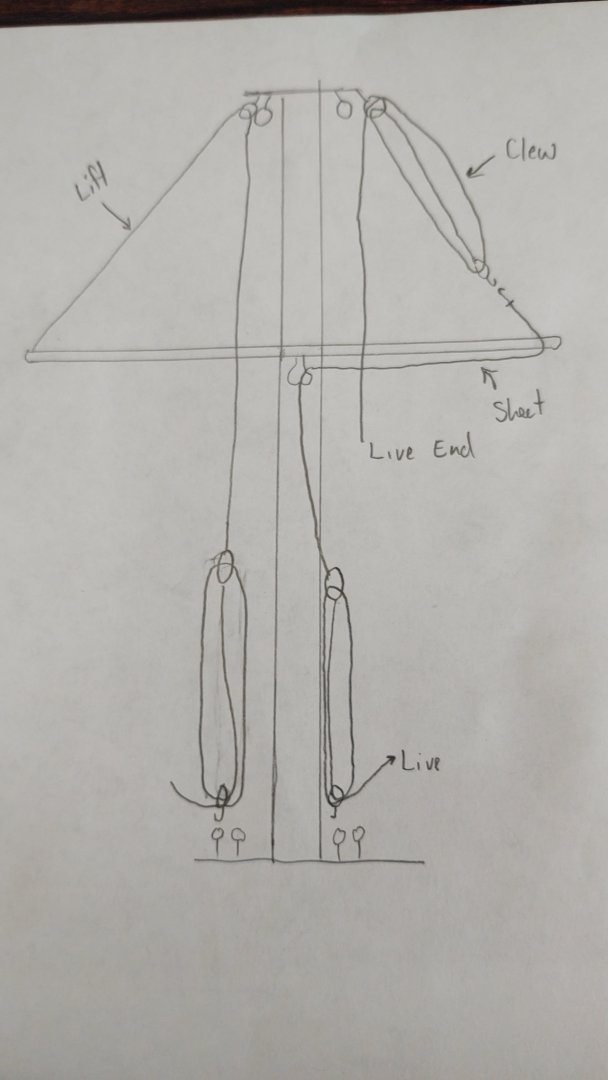
Hi Tom, Here is what I mean by deck mounted tackles. If you look at this photo of Endurance (best I could find on a quick search that shows it) and have a look at the blocks that I circled, those appear to be the tackles for the main course sheets and lifts. Here is the same photo without the circles. On the Fish (and based on photos on Discovery as well), those tackles are set up like so (pardon my terrible drawing): So the live ends of the course lifts and sheets are a double block (the circled ones in the photo). The block has the static end of another line that is run through a block on the deck near the mast, back through the first block and then down to the deck mounted block with the live end now available for belaying. This makes it much easier to operate the lines - and the course yards and sheets are going to be the most massive and hardest to move. Rigged like this, it makes complete sense to belay on either a fife rail around the base of the mast (which I gather is not present on Endurance) or on the spider band. Anyway, the model may not have planned for such tackle, which is fine, all models are simplifications. Either way, yours is looking great! Regards, George
- 206 replies
-
- 2
-
-
- Endurance
- Shackleton
- (and 2 more)
-
Looks like it might vary. Both Anatomy of the Ship for USS Constitution, and if you look here: https://ussconstitutionmuseum.org/2023/08/07/main-mast-work-continues/, it seems like Connie has ratlines all the way to the top. Similarly, here is Niagara (from FLIKR) That kind of makes sense since the lubber's hole is pretty useless if you can't reach it with the ratlines. I wouldn't lose any sleep over them though - they will be next to invisible. Regards, George
-
Ain't that the truth. You need some number of base units, and I don't have an issue with the meter, the liter is 1000 cm3, the second and volt were pretty much universal. But this proliferation of named units that don't tell you what they are measuring: webers, grays, bequerels, sieverts, grays, teslas, etc., etc drive me nuts. I mean I know what they measure because I remember some of my physics,, but I would have to look them up to see how they mapped to base units to use them mathematically (not that this has been much of a problem since I took physical chemistry in grad school, but still). And with that I will ask those annoying neighbor kids to get off of my lawn, and move on. Regards, George
-
Thanks Rick! The wood is bass, 3/64 by 1/8. The bulwarks are going to be made from 1/32 by 1/8 planks with 3/32 stanchions.
-
And weight calculated in stones. What's up with that? And capacity in tons burthen
-
Well, there's the fact that it looks great! The holes in the top are fairleads, and that is their purpose on the ship (basically keep the lines from fouling each other). Whether the main spar lifts were meant to go through the fairleads or through the lubber's hole is specific to your ship, and I have no insight there. Earlier you mentioned not worrying too much about where to put the lines. I agree with that assessment - most belaying plans are at best recommendations - ship captain's (and crews) belayed where it was convenient. if you look at generic belaying plans, things like the course spar lifts, course clew garnet, course and topgallant sheets tended to be belayed by the mast. This makes sense since they were often operated with tackles that were mounted to the deck near the mast, and who wants to run the live end of a deck mounted tackle to the bulwarks. I don't know if you have such a tackle on Endurance but there is on Discovery and there is a certain logic to such an arrangement. Your mileage may vary. Regardless, looking fabulous. Regards, George


.jpg.65da690e91349ea057288d2db9300c9c.jpg)