HOLIDAY DONATION DRIVE - SUPPORT MSW - DO YOUR PART TO KEEP THIS GREAT FORUM GOING! (Only 75 donations so far out of 49,000 members - C'mon guys!)
×


gak1965
-
Posts
722 -
Joined
-
Last visited
Content Type
Profiles
Forums
Gallery
Events
Everything posted by gak1965
-
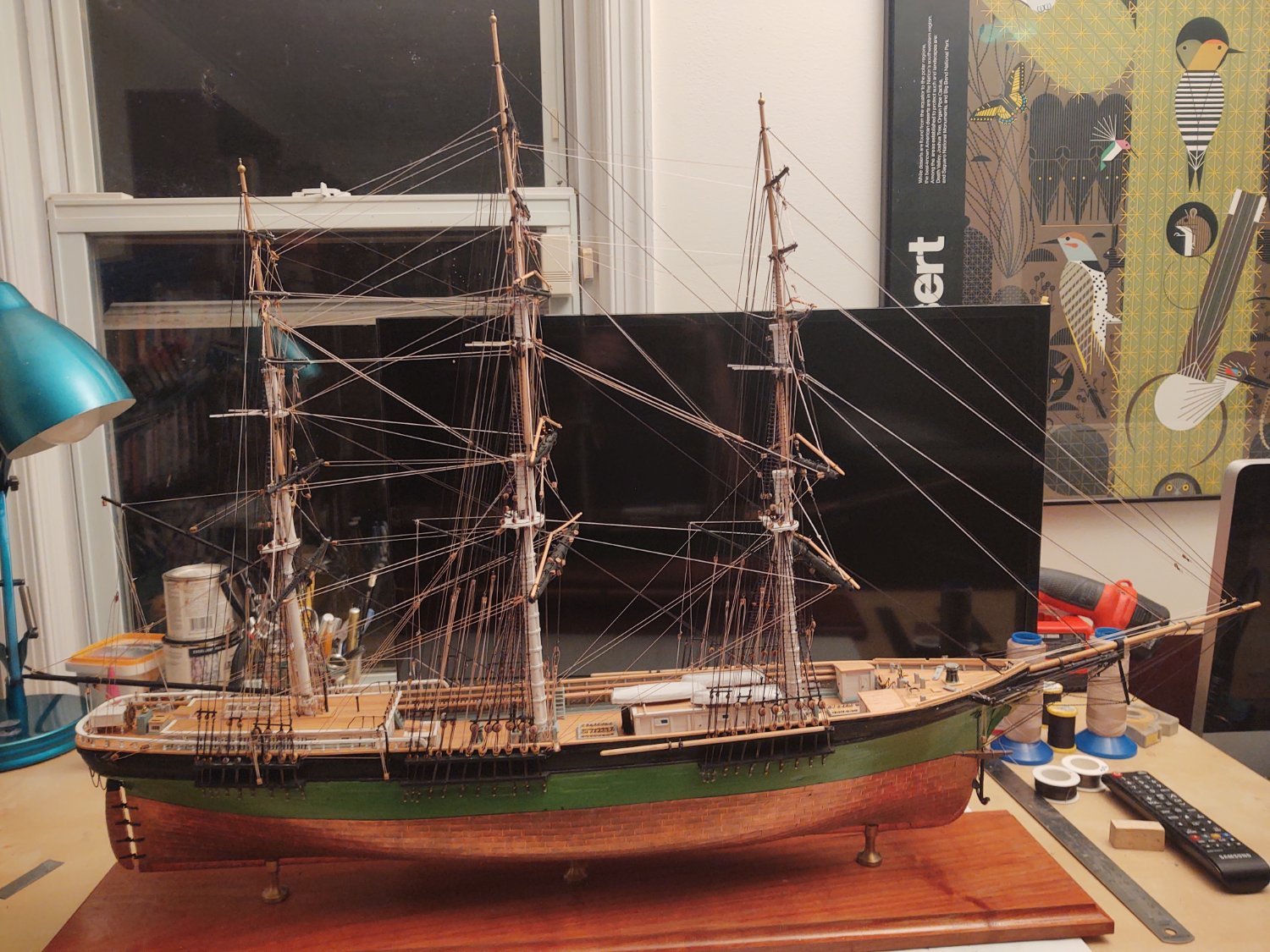
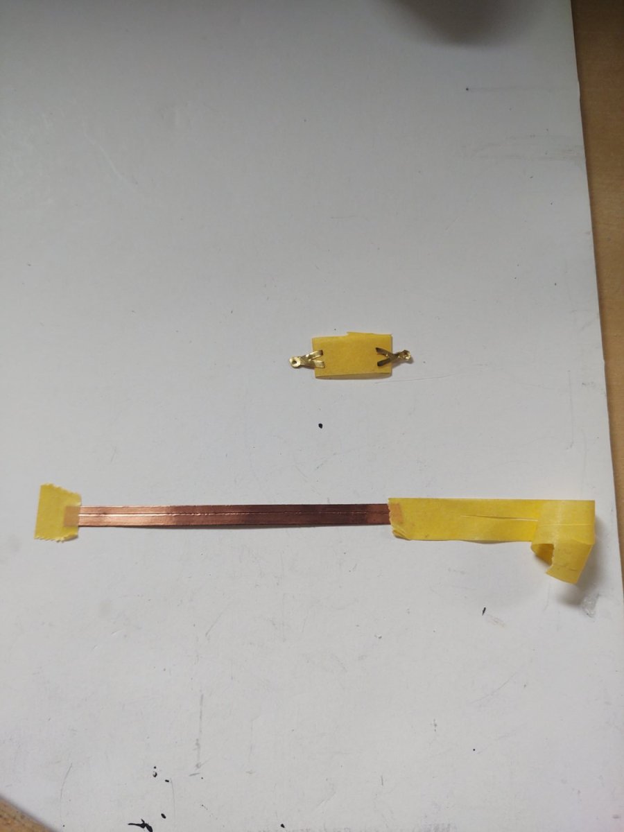
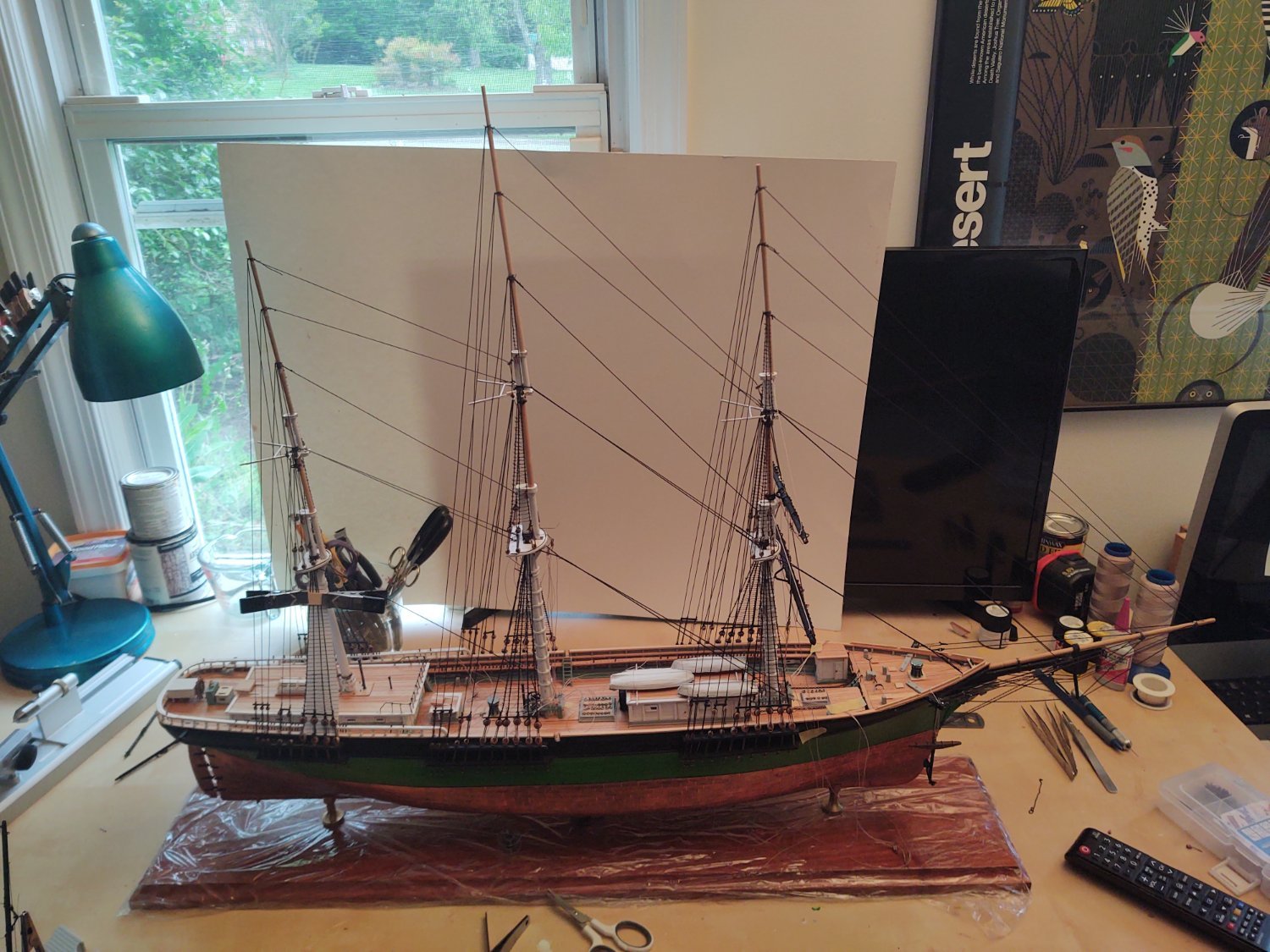
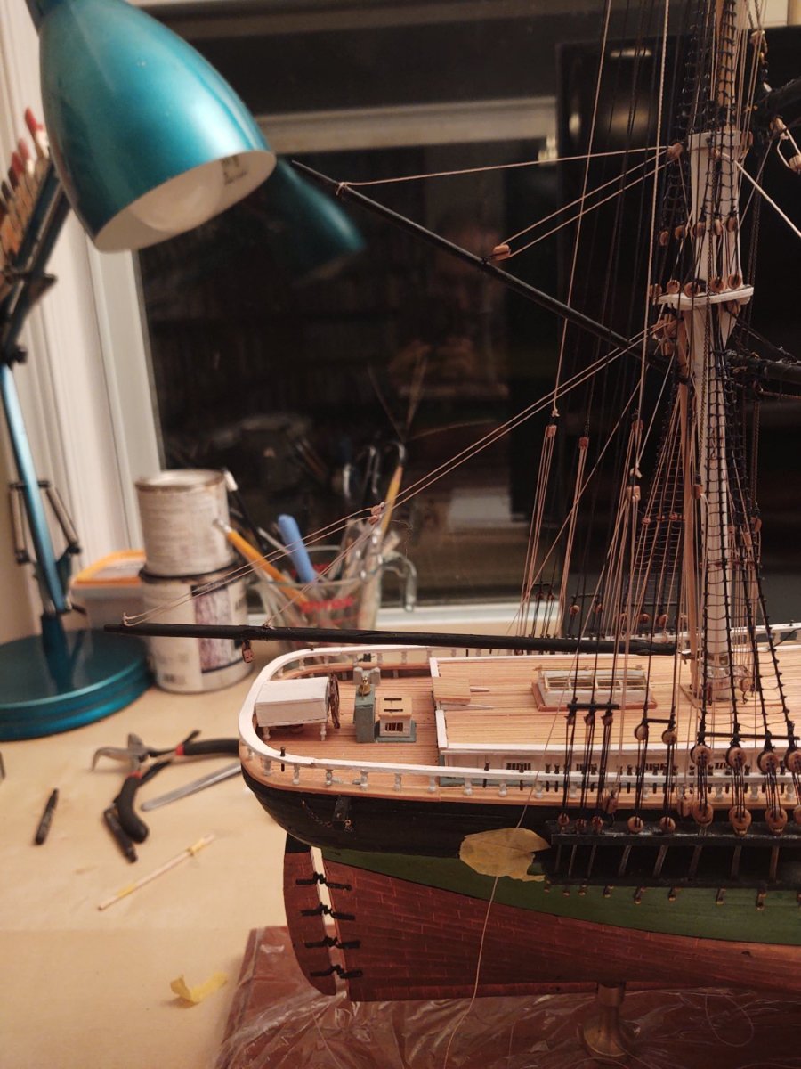
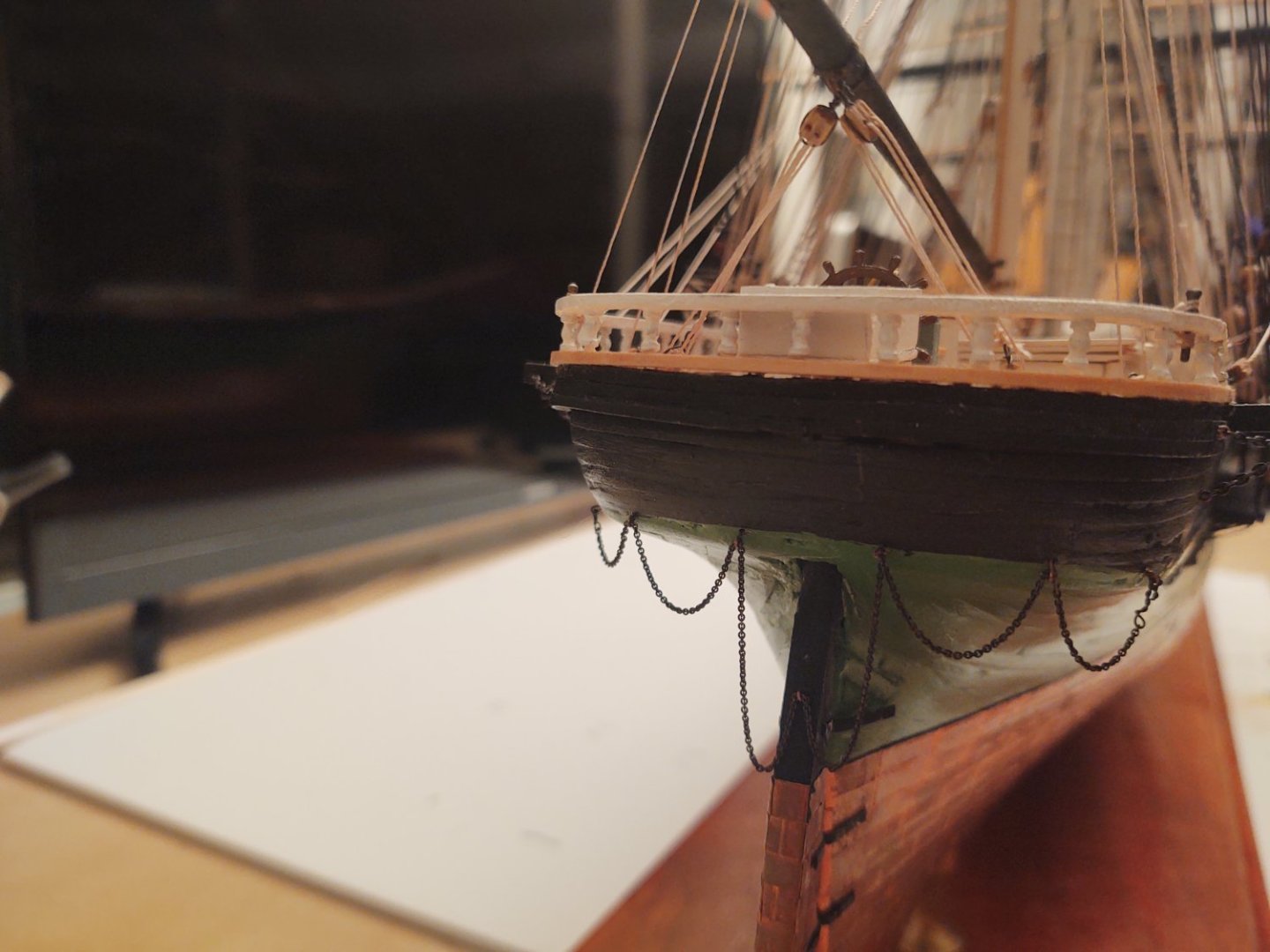
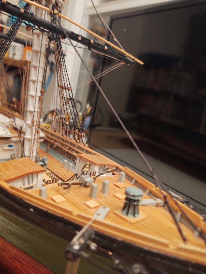
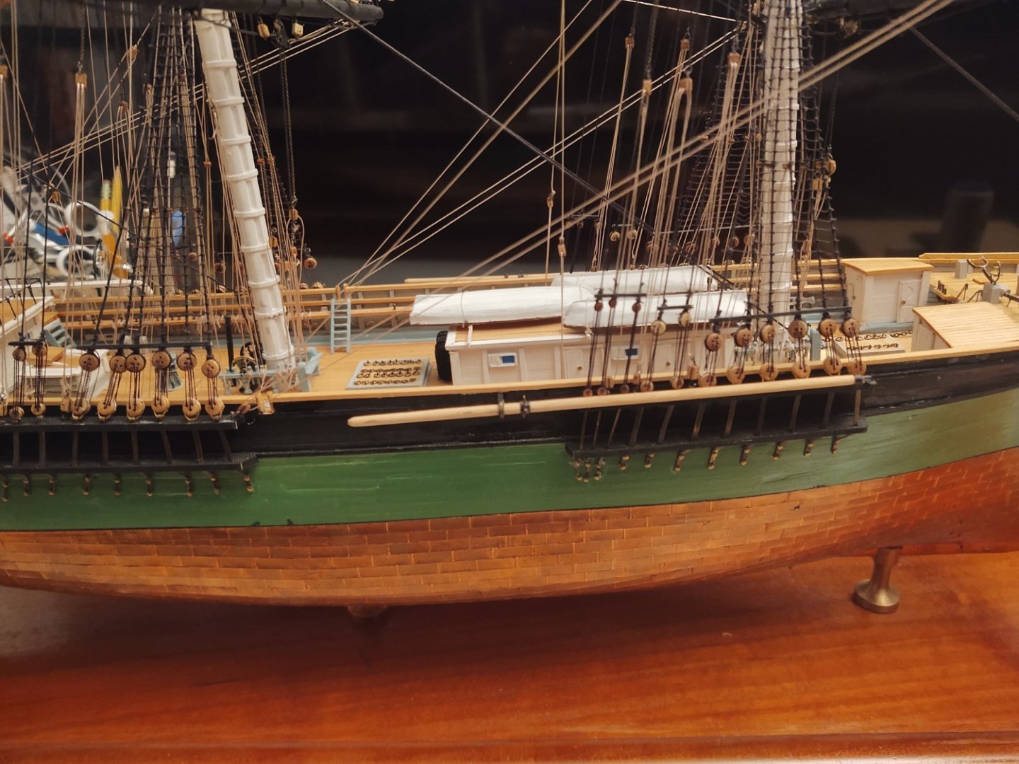
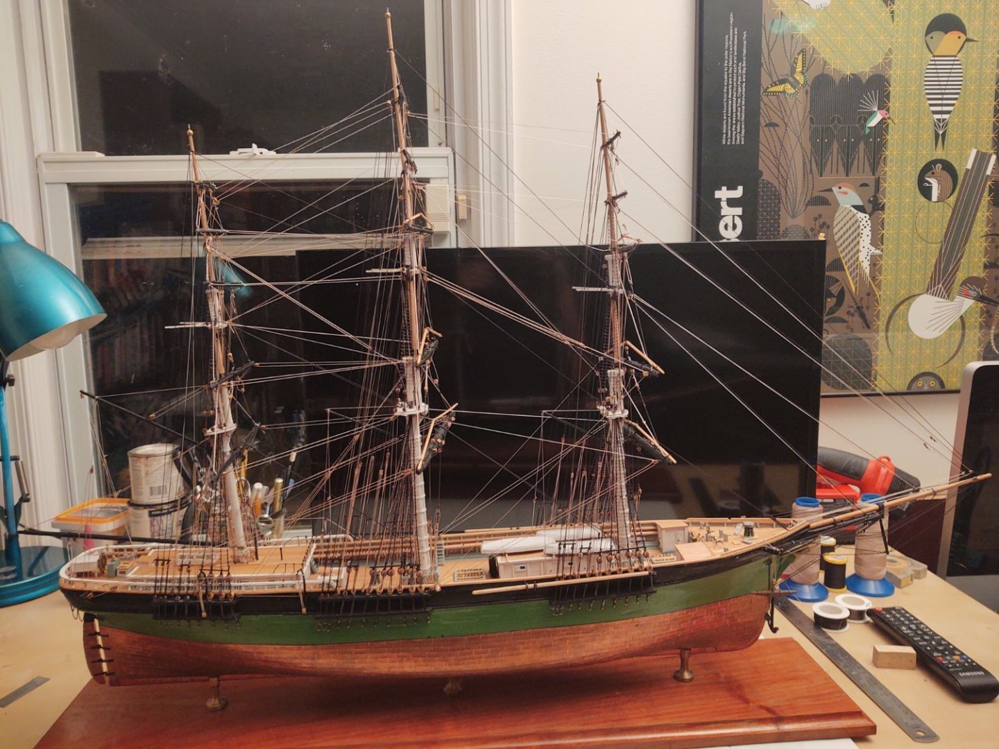
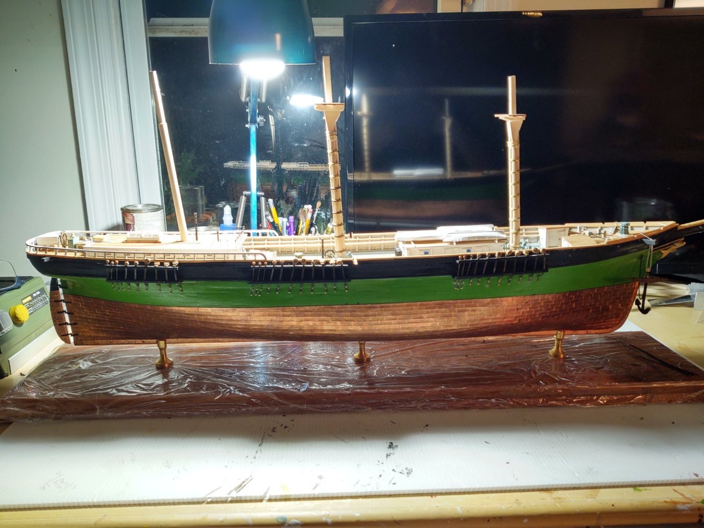
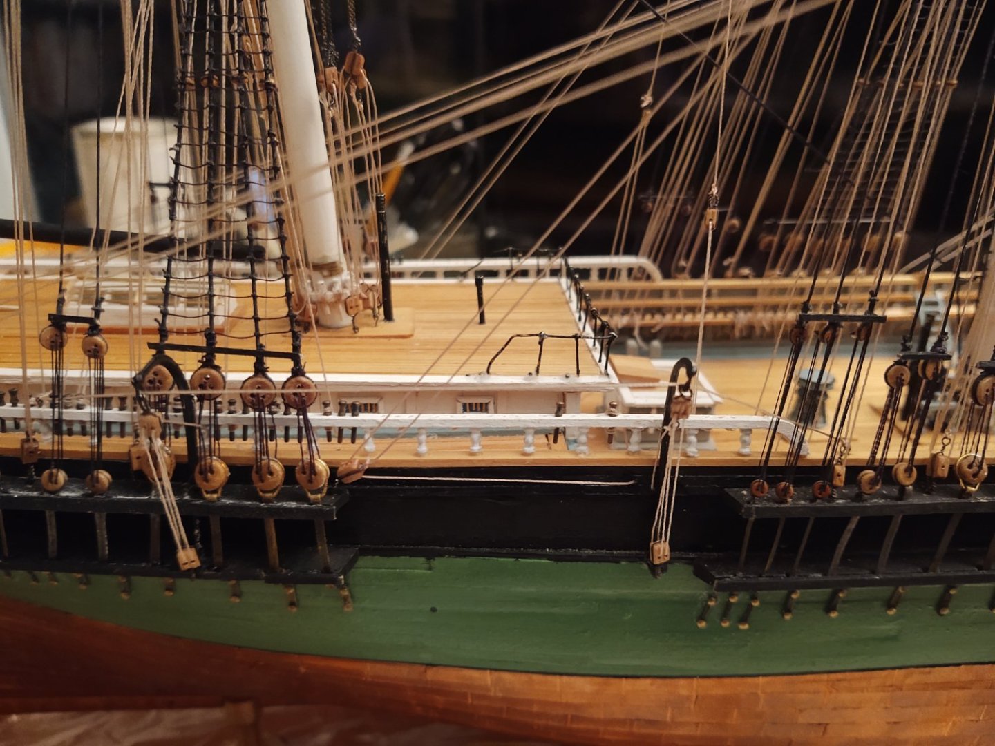
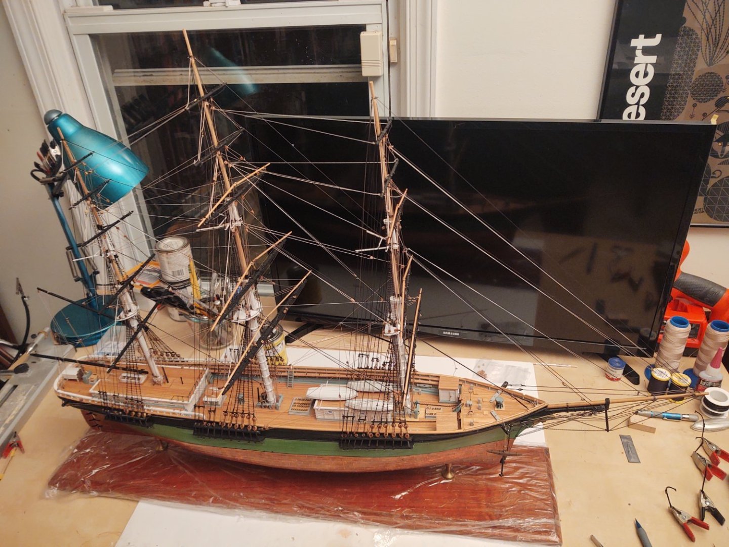
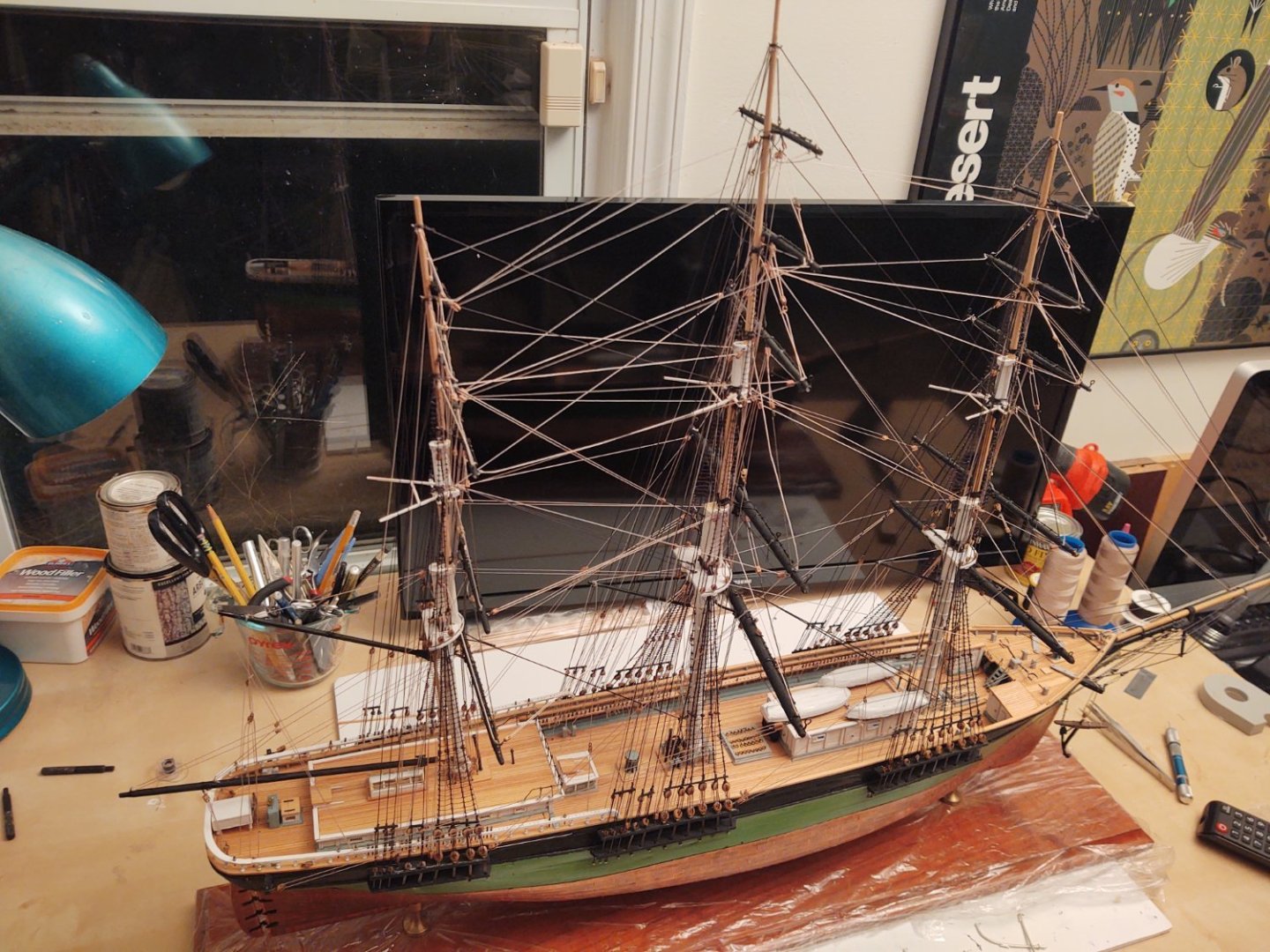
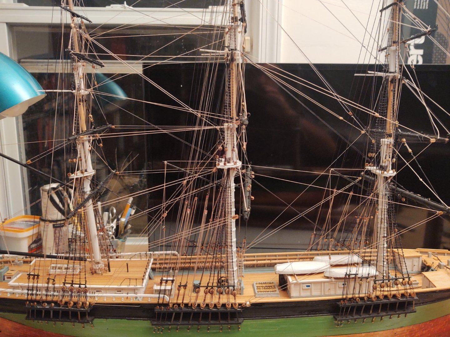
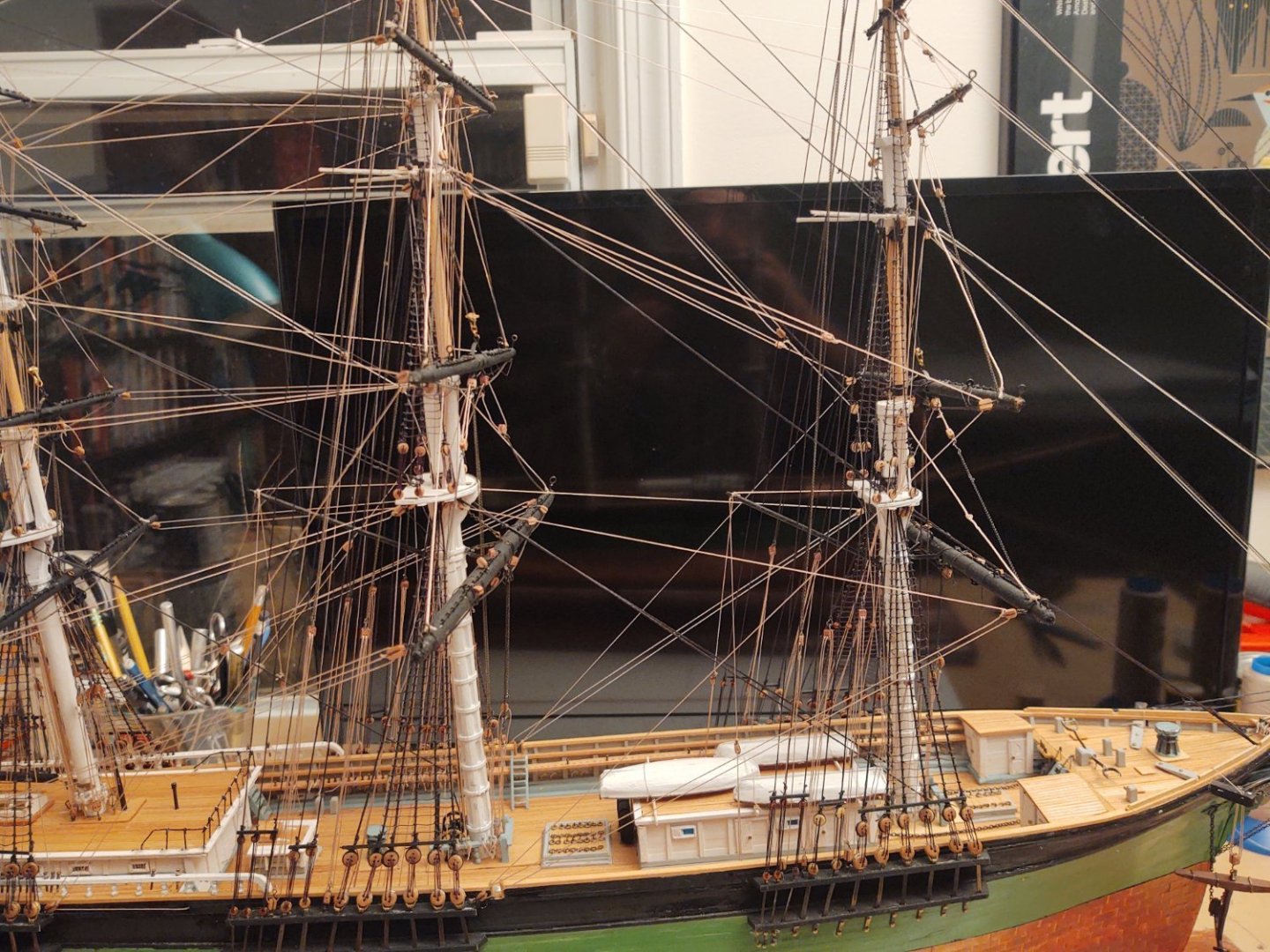
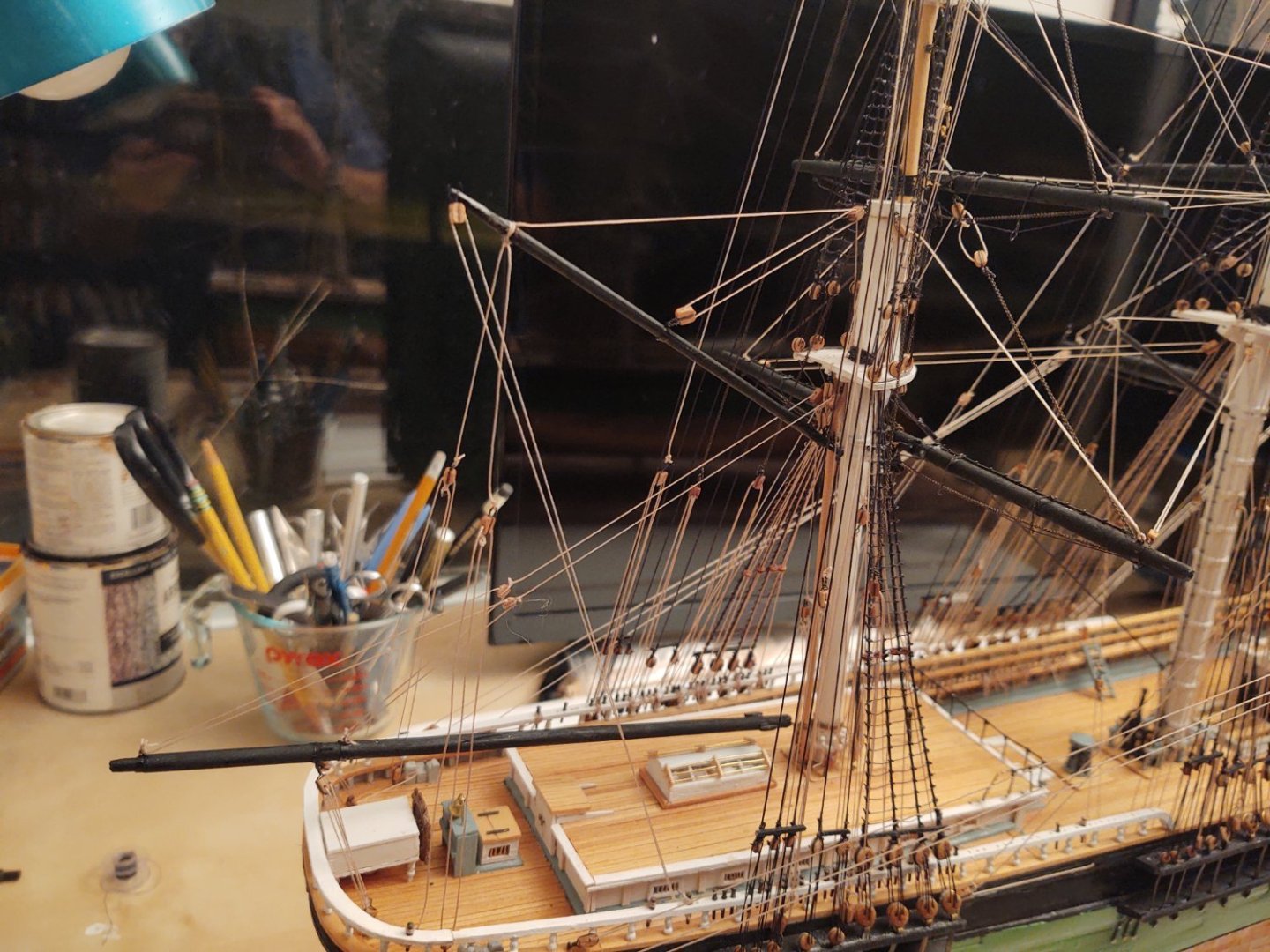
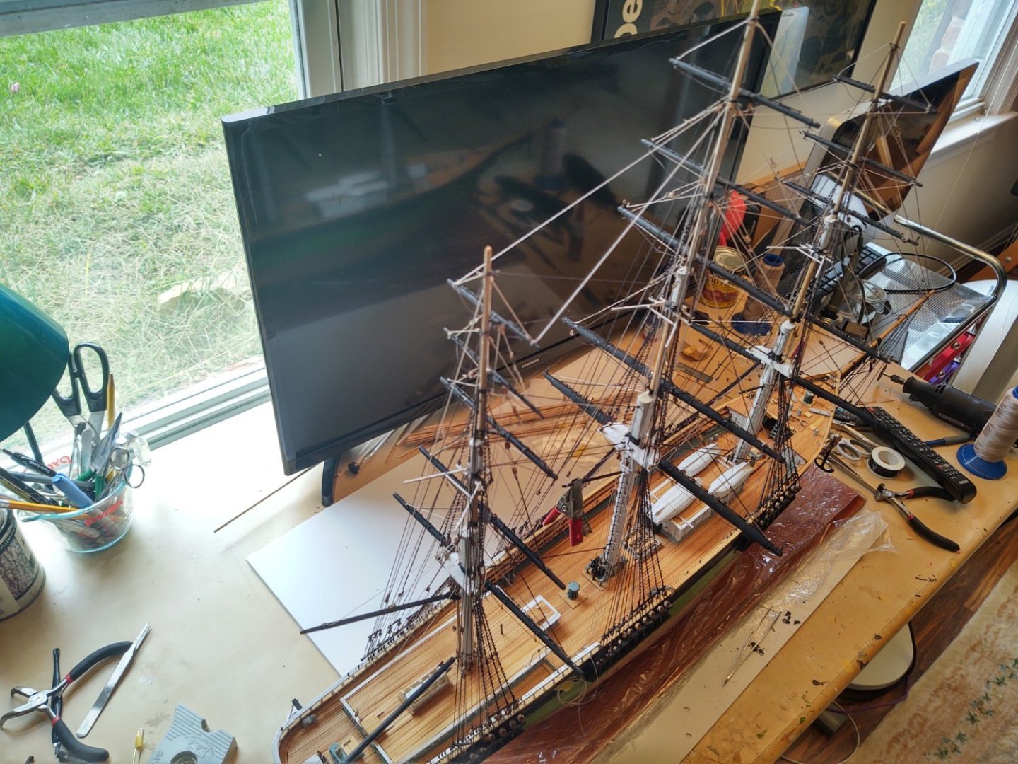
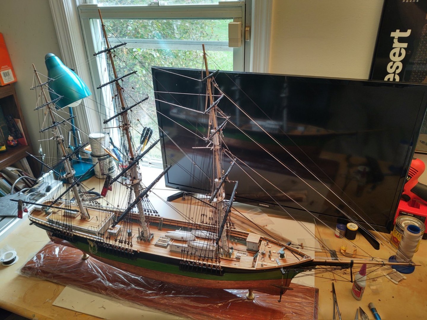
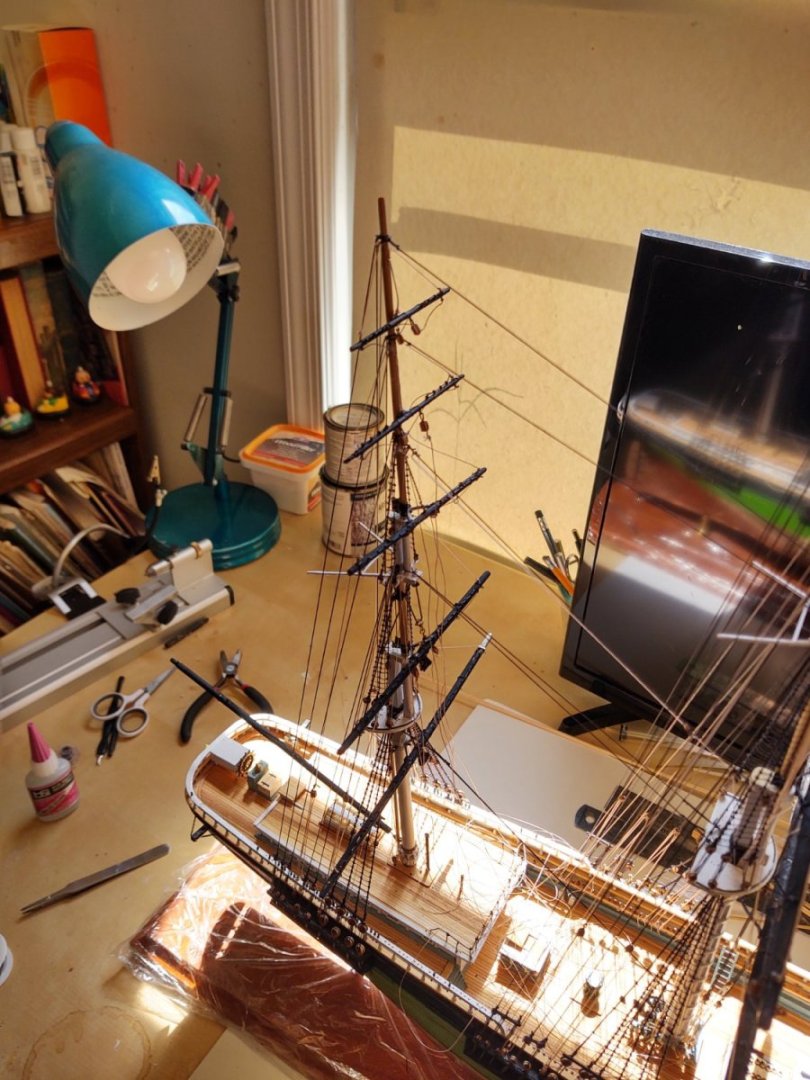
 Well, I still need to buy some transfer letters to make the name, but I've removed the Saran wrap covering the base and I'm calling this one FINISHED. 2 years, 355 days after starting. I don't have a lot of great photos (I'll take them during the day and in a better setting), but I've got a couple of the now completed ship. First, couple of snaps of the last steps. The preventers on the rudder: The forward bell: The lower, fore stuns'l boom mounts (I lost one of the ones shown and had to remake it), and the mounts+booms in place. The mount was made from sheet brass, the boom iron from copper venture tape painted black, and boom rest from 1/16 by 1/32 brass, with the lower support made from annealed steel wire. Finally, please take a journey with me, having a look at the ship at approximately 6 month intervals. NOVEMBER 2020: MAY 2021 (6 months) NOVEMBER 2021 (1 year) MAY 2022 (1.5 years) NOVEMBER 2022: (2 years) MAY 2023: (2.5 years) And finally, completed, November 4, 2023: (3 years) Thank you all for your suggestions, assistance, and for following along so that I didn't give up somewhere along the way. As I said, I'll post more, better pictures in a couple of days. Now I need to figure out what is going to be next. Regards, George


- 602 replies
-
- 16
-

-

-
- Flying Fish
- Model Shipways
- (and 2 more)
-
No new photos today. But, completed: Portside davits, guy, and boat tackle Gilded balls on mast trucks: I used a couple of about 3 mm beads from my wife's stash, used a belaying pin to represent the top coming from ball, painted them gold and installed them. Preventer chains on the rudder. Somehow I missed them before. That leaves: Stuns'l booms on hull: 2 Forward bell: 1 Decals: 3 I'm starting to wonder if I dreamed the decals. There is a flag sheet in the parts list, but no decals. I will try to find some good transfer letters to make the name. My guess is that there are train ones that will work. If that's the case, all that's left are the booms and the bell. I'll go over the ship and see if I'm missing anything, but with any luck, I'll be done this weekend. Regards, George
- 602 replies
-
- 2
-
-
- Flying Fish
- Model Shipways
- (and 2 more)
-
Honestly the casks look great as is. Don't know that I would bother doing anything to them Regards, George
-
Okay, well, I have mounted the starboard side davits. Here is a photo: The photo isn't great, but here are the basics. Fore davit on a small platform I built at the planksheer. Aft between shrouds 3 and 4. I put the guy in, but simplified the rigging. The plans show a bolt at the after end, and a tackle, belayed to a pin on the main rail forwardl. I just ran it to a eyebolt on the main rail. I looked at rigging the boat tackles in an X pattern but didn't like the look, so they are rigged vertically, with the hooks attached to the lower channel or the platform directly beneath the davit. It doesn't look vertical (it's an artifact of the photo), but it is. The list: Stuns'l booms on hull: 2 Davits: 4 2 Boat tackle: 4 2 Guy wires on davits 2 1 Gilded balls on mast trucks: 3 Decals: 3 Total = 13 Regards, George
- 602 replies
-
- 4
-
-
- Flying Fish
- Model Shipways
- (and 2 more)
-
Yeah, there are two things constraining the location of the forward davit - need to be aft of the freeing port and forward of the sheave for the main course brace. As depicted on both paintings, they seem different than the davits on something like the Cutty Sark, in that the guys would seem to limit their ability to rotate. In that case they would only be able to easily launch and recover the specific boats in the davit, more like modern lifeboat davits. How the heck they launched the boats stored on the cabin is a mystery to me. You'd need to manhandle them over to the davits first at a minimum, and if they can't rotate, getting the boat in place must have been challenging, but I could well be missing something. Regards. George
-
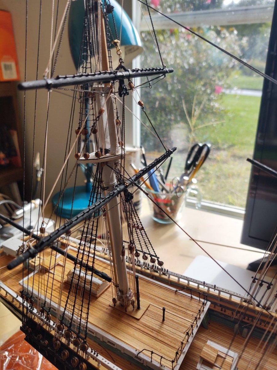
Well, the yard mounted stuns'l booms are done. They are shown as per the plans, which is to say tied to various convenient halyards. Here are a couple of photos of the ship and the booms: In the first photo you can see the boat davits drying after being painted black. I ultimately drilled the hole for the aft davit between the 3rd and 4th shroud as in the Buttersworth painting rather than the plans (between shroud 1 and 2) or the China Trade painting (between the shrouds and backstays). They are drilled on both sides, ready to be mounted once the paint dries. The list: Stuns'l booms on yards: 12 Stuns'l booms on hull: 2 Davits: 4 Boat tackle: 4 Guy wires on davits 2 (maybe) Gilded balls on mast trucks: 3 Decals: 3 Total = 18 We will see if I ultimately put the guy wires on the davits. They would need to be run behind the shrouds and backstays and that area is really inaccessible right now. I'll probably try, but there is a limit to how much damage I'm willing to do at this late stage to add two lines. FWIW, for those that are working on the Fish, it might be worth installing these before the course and top braces so that you can access things a little easier. Anyway, the end does appear to be approaching. I'll probably do the davits, then the two hull stuns'l booms, and see if my wife has any beads of the right size to make the gilded balls for the mast trucks. The decals will be the last step. Not sure if I'm going to apply the name directly or whether I'll put it on a very thin piece of black painted wood. It needs to be discreet, there were no head or trailboards. I have a case that my father bought for the Revell USS Constitution* I made for my parents, but which he dispensed with when they moved into his current apartment. The case was way too tall for the Constitution, and it's too tall for the Fish at the same scale, so I'm going to cut the wooden corner elements shorter and have a glazier cut the glass down to appropriate size, but it's already available. Hopefully I will finish her by the end of this weekend, as November 14 will mark 3 years of work on this project. I'm really looking forward to closing this one out and working on something new. I appreciate everyone who has looked in and helped me along. Regards, George * PS: There is a bit of a story as to why I gave my parents a Revell USS Constitution. My maternal grandfather (who died in January 1969) built plastic models while he was living with us from 1967-1969. He built two Revell Cutty Sarks (and the Nichimo 1:200 Yamato, the notorious flat bottom Revell USS Midway, etc.) which were displayed in our house. Why two of them - I don't know; I assume he wanted to do better on the second try, although they both looked great to me. He was working on the Constitution when he died. I tried to pick it up when I was about 12 years old, but it was beyond my skills, had been sitting in the house for 8 years and was probably missing pieces, and I ultimately gave it up. In the interim, my brother, sister, and I had pretty much destroyed both of the Cutty Sarks playing with them. When I took up modeling again as an adult, I decided to build the Constitution that my grandfather never finished, and to give it to my parents to replace the ships we destroyed as kids. I think that they appreciated it, particularly my dad, as my maternal grandfather had been so kind to him after his own parents more or less disowned him for marrying my mother.
- 602 replies
-
- 7
-
-
- Flying Fish
- Model Shipways
- (and 2 more)
-
Thanks Rick! I look at yours to see how I should have done it. I've been working on the stuns'l booms. The yard mounted ones are all shaped, stained, and 8 of them are mounted. I'll post some photos once they are all mounted and the ties are in place. In the interim, I was hoping someone might have some insight about the location of the of the davits. (I've started prepping them for installation) The China Trade painting and the Buttersworth painting both show black davits (so that is clear) and the forward davit mounted just aft of the mainmast channels but one shows the after davit mounted between the 3rd and 4th mizzen shroud (counting from the forward end) and the other shows it between the mizzen shrouds and the mizzen lower backstays. If anyone has any insight from other McKay clippers (or wherever) I would appreciate it. The practical answer would seem to be to put it between the shrouds, (a) because there seems to be more room there to drill a hole and the shrouds are a little more out of the way than the backstays (plus there is currently a block from one of the halyards there) and (b) because it would seem to separate the fore and aft davits much longer than the apparent length of the boats. I'm actually not going to mount the ships boats (they are off on business somewhere), mainly because the castings are so bad, so it won't matter in that sense, but I would prefer to do this properly. Any insights appreciated. Regards, George
- 602 replies
-
- 1
-
-
- Flying Fish
- Model Shipways
- (and 2 more)
-
Lots of progress Jared; looking absolutely great!
-
They do have good customer service. I needed more brass for my Fish
-
Well, the Fish is rigged. I still have some things to do, but we are definitely on the home stretch. The list: Stuns'l booms on yards: 12 Stuns'l booms on hull: 2 Davits: 4 Boat tackle: 4 Gilded balls on mast trucks: 3 Decals: 3 Total = 28 As always thanks for looking in, George

- 602 replies
-
- 10
-
-
-
- Flying Fish
- Model Shipways
- (and 2 more)
-
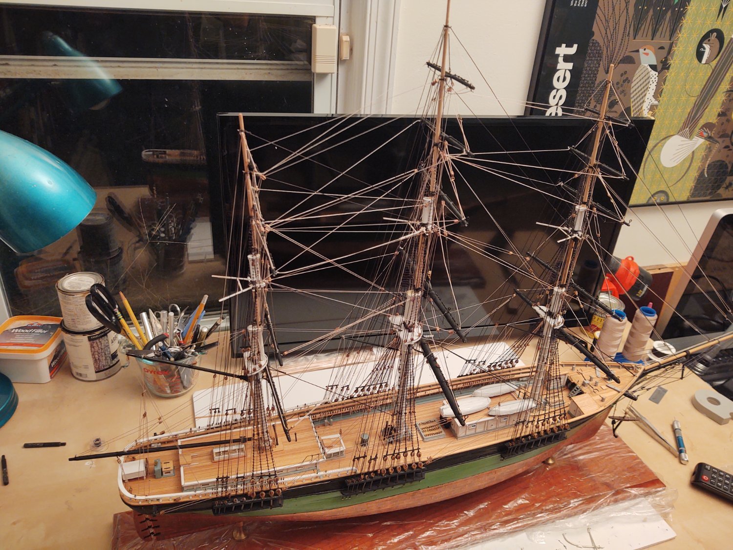
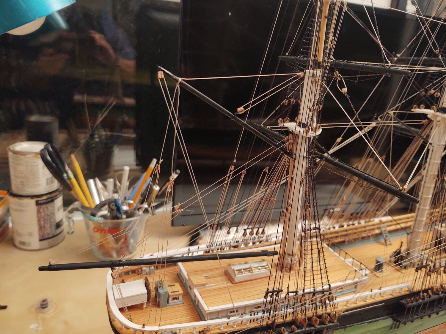
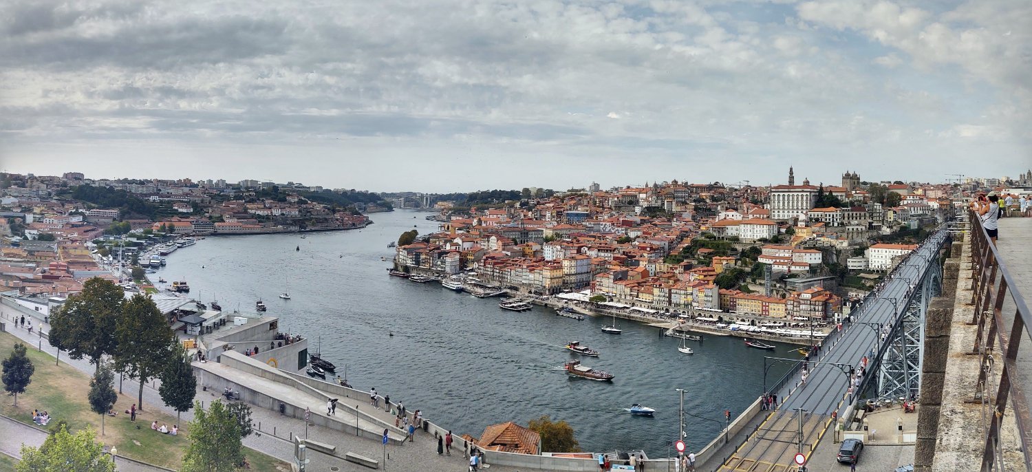
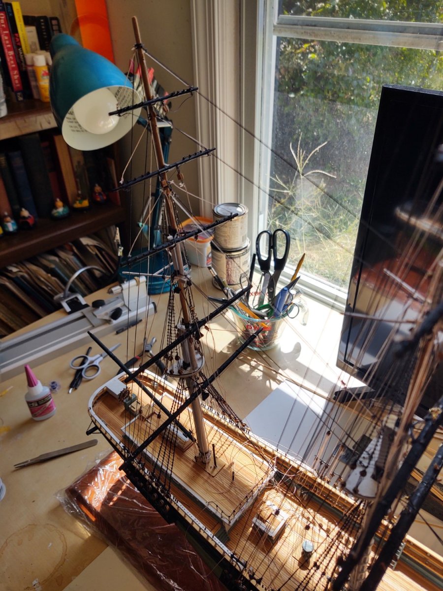
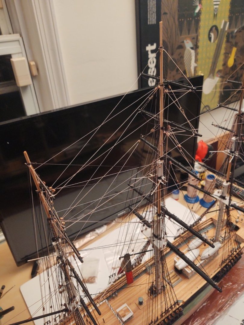
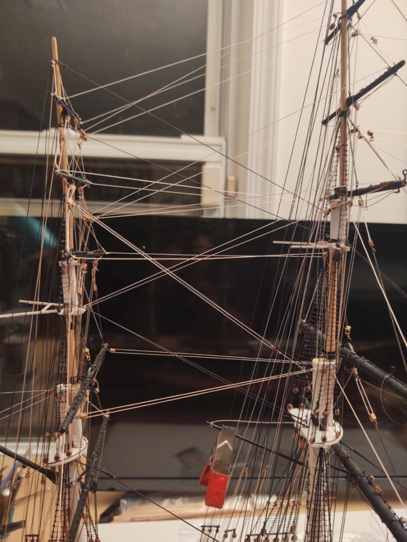
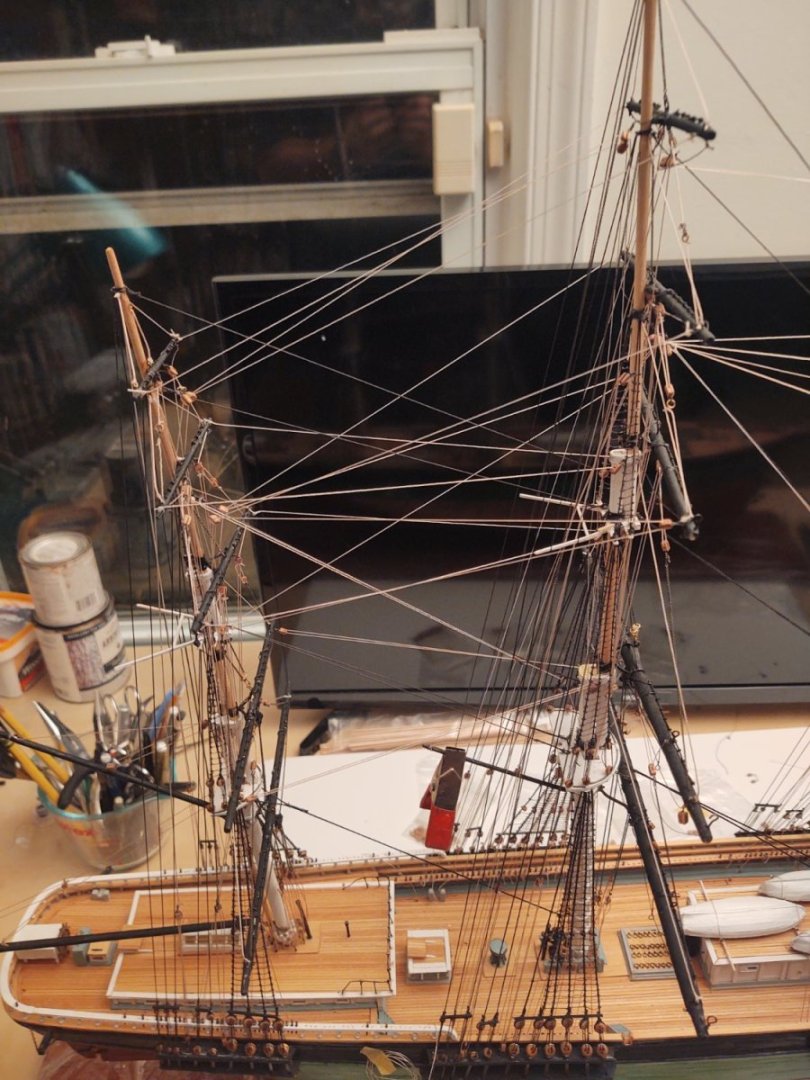
Well, we got back from vacation on Monday, a day late. Unfortunately, United downchecked the aircraft after we had boarded, so we waited for 5 hours before they cancelled the flight. Given that it was avionics, I don't know why they didn't just cancel it right away - we would have found something more interesting to do in Lisbon than just sit around the plane (at least they let us walk onto the gate area). Anyway, Portugal was very nice - we took a boat trip up the Duoro River from Porto, ate great and had lots of delightful wine and Port, so, can't really complain. One shot of the Duoro in Porto itself, taken from the Mosteiro da Serra do Pilar (which is technically in Vila Nova de Gaia (Porto is on the north side of the river) where all of the Port houses are. You can see some of the boats used to transport the wine - unfortunately I forgot to take a photo of a rabelo boat, the old school shipping sailboats. The bridge in the foreground is the Ponte Luiz I which was designed by a student of Gustav Eiffel, hence why the arch may remind you of some other structure.... So, back to the ship. Since I've been back I've been working on the braces. I have now completed all but the fore course and top, main course and top, and mizzen course, which is to say, I've been attaching main and mizzen braces. Here are some photos of the work to date: And here is the ship in its current state: I also wound up repairing a previously mounted brace that was interfering with the spanker. So, the reduced list: Spencer gaff: 2 Braces: 30 10 topping lifts: 2 Stun'sl booms on hull: 2 vangs: 4 2 Stun'sl booms on yards: 12 Spanker boom: 1 Davits: 4 sheets: 2 Boat tackle: 4 Topping lifts: 2 Decals: 3 Spanker gaff: 1 Gilded balls on mast trucks: 3 peak halyard: 1 Throat halyard: 1 vangs: 2 ensign halyard: 1 Change: 0 Additions -12 (12 braces) Net = -12 Remaining items: 45 Finally dropped below 50. Of course, the remaining 10 braces are the complicated ones, each probably worth 2 normal braces. But, I'm sticking to the 45 items number. I'm also probably going to start fabricating the stun'sl booms. The kit only provides 5/32 dowels for them, but I bought some 1/16 dowels and am going to try to make them scale appropriately to the yards. Main course: 3/32 Main top: 1/16 Main topgallant: 1/16 (not sure - going to see what it looks like, may sand it down) Fore course: 1/16 Fore top: 1/16 (not sure - going to see what it looks like, may sand down a bit) Fore topgallant: 3/64 (ish) - basically going to sand the 1/16 dowels Those 5/32 dowels are 9 inches at scale. Except for the main - that's way too big. I can try to lift the diameters by measuring the plans, but I'm probably just going to eyeball it. As always, thanks for looking in! Regards, George

- 602 replies
-
- 5
-
-
- Flying Fish
- Model Shipways
- (and 2 more)
-
Very nice casks! I tossed the kit one as well, as it was very poorly cast, even compared to the one you have. FWIW, I once accidentally bought brass jewelry wire that was apparently coated to resist tarnish, and as a result it wouldn't blacken. Maybe that's what you have going on there. Regards, George
-
Another option for the bunts and leeches is to leave the blocks on the yard and tie a knot in the sail end so that the ends of the lines tied to the jackstay on the photos is held by the block on the yard rather than by being tied onto the jackstay George
-
Heading on vacation for a week tonight, so last update for a bit. What I've done in the last couple of days (not a huge amount, but something). Attached and anchored the spanker boom topping lifts with their tackles. Attached the main spencer gaff and its topping lift Installed the mizzen skysail braces Installed lines for the main spencer vangs (although not the vangs themselves). I'm avoiding the vangs for now so I can get easier access to the pin rails. So a couple of views: BTW, I guess I need to confess that I have not slavishly copied the belaying plan. I have, to paraphrase the instructions, put things where convenient as needed. This has been particularly true of the braces. I know - a shocking confession - but the plans were guides, and they are being belayed at least near where the plans suggest. Reducing the list: Spencer gaff: 2 Braces: 30 22 topping lifts: 2 Stun'sl booms on hull: 2 vangs: 4 2 Stun'sl booms on yards: 12 Spanker boom: 1 Davits: 4 sheets: 2 Boat tackle: 4 Topping lifts: 2 Decals: 3 Spanker gaff: 1 Gilded balls on mast trucks: 3 peak halyard: 1 Throat halyard: 1 vangs: 2 ensign halyard: 1 Change: 0 Additions -6 (2 spanker topping lifts, 1 spencer gaff, 1 spencer gaff topping lift, 2 braces) Net = -6 Remaining items: 57 As always, thanks for looking in, and I'll hopefully have an update in about 10-14 days. George

- 602 replies
-
- 5
-
-
- Flying Fish
- Model Shipways
- (and 2 more)
-
@Jared, you might consider strengthening the spreaders a bit. I glued a strip of brass on the underside before painting. It's not obvious and it kept things from breaking on more than one occasion.
- 431 replies
-
- 2
-
-
- Flying Fish
- Model Shipways
- (and 2 more)
-
I was a microbiologist as an undergrad, and my PhD is in Molecular Biology and Biochemistry. I left the lab in the mid '90s to do computational work full time.
-
Thanks - appreciate the compliment. I tend to find that my hands start to shake after a certain amount of very fine work even without COVID, although it is annoying that I am still testing positive. With that said, a short update. I finished the remaining sheets and clews on the mizzen royal and skysail yards. And, I've started dealing with the spanker. I've mounted the spanker gaff and boom. The gaff has both the throat and the peak halyards fully mounted. I've also put in the topping lifts, but I'm not going to mark them as done because I have to put in the tackles that connect to the live ends. So, the list: mizzen yards: 5 Jib halyards: 4 lifts: 10 Jib downhauls: 4 sheets: 8 Staysail halyards: 2 clews: 8 Staysail downhauls: 2 halyards: 4 Spencer gaff: 2 1 Braces: 30 24 topping lifts: 2 1 Stun'sl booms on hull: 2 vangs: 4 2 Stun'sl booms on yards: 12 Spanker boom: 1 Davits: 4 sheets: 2 Boat tackle: 4 Topping lifts: 2 Decals: 3 Spanker gaff: 1 Gilded balls on mast trucks: 3 peak halyard: 1 Fairleads on shrouds: 8 Throat halyard: 1 vangs: 2 ensign halyard: 1 Change: -3 (only 1 throat halyard, not doing 2 outhaul sheets) - also adjusted topping lift to spanker boom, and throat halyard to gaff) -8 (spanker gaff, Spanker boom, peak halyard, throat halyard, 2 clews, 2 sheets) Net = -11 Remaining items: 63 As always, thanks for looking in, and for the likes and comments. Regards, George
- 602 replies
-
- 4
-
-
- Flying Fish
- Model Shipways
- (and 2 more)
-
Yeah, the case for my Niagara cost more than the kit. It was a little over $500 for the wood pieces (Bluejacket) plus the cost of the glass/plex and the poly. That said, there is a lot of work out into these things, it's nice cherry wood and it seems safer and more secure...
-
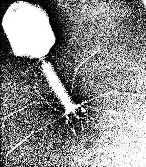
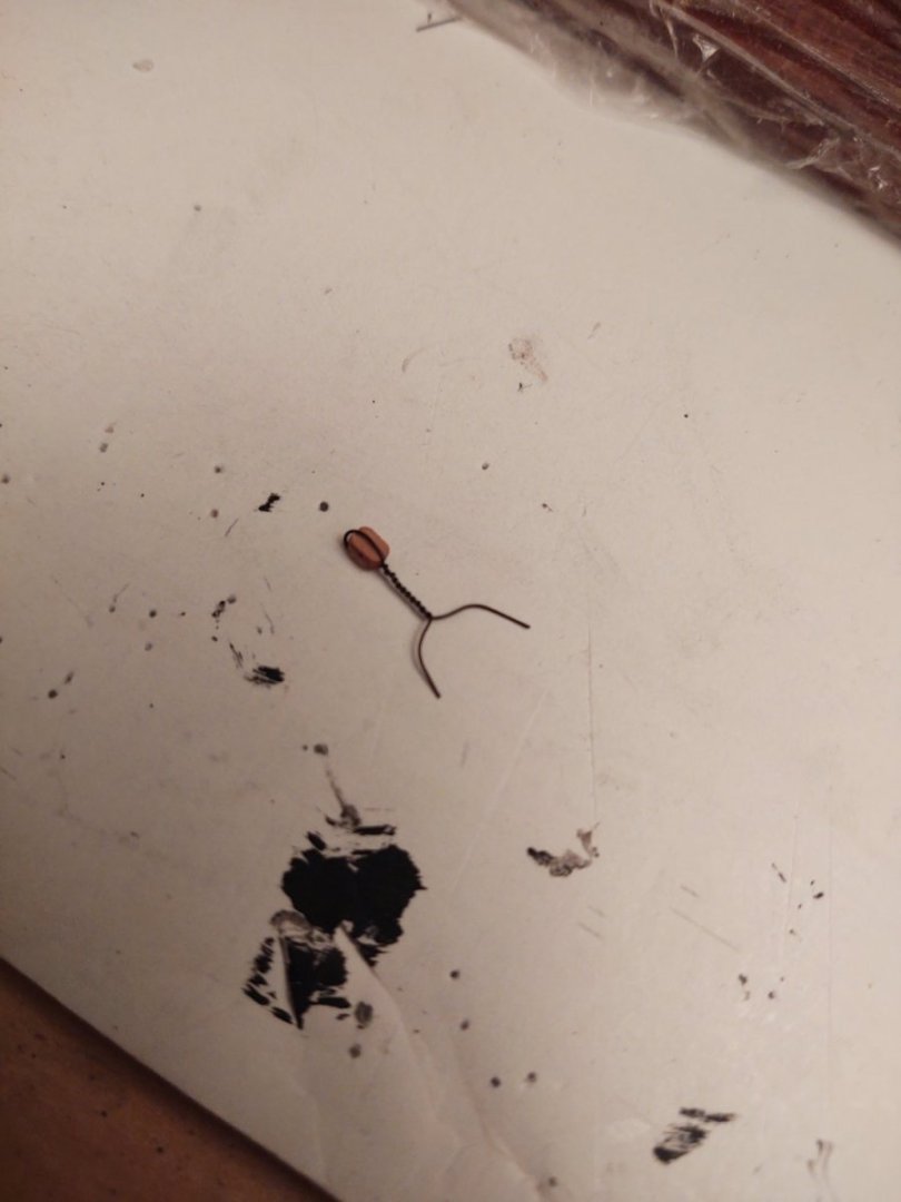
Thanks again for all the well wishes! I was back to work (from home obviously) last Monday but I am still testing positive 9 days later which is rather annoying. Still grateful for having a mild case, despite the long testing tail. Between COVID and the dreadful weather I've had some time to work. So, current status. The mizzen top and topgallant sheets (the chain ones), their tackles the and associated clews are mounted on both sides. The royal and skysail sheets and clews are mounted on the starboard side only. I have lines made but have only installed the royal clew as my hands were starting to shake. Not ideal when there are lines and yards everywhere. While on virus themes, as I was stropping blocks with some wire, just how much they resembled bacteriophage T4, an E. Coli virus that was a common genetic research organism while I was an undergrad and grad student. (Photo CC-BY from Wikipedia) Anyway, I doubt current students bother with this sort of thing since we only used it because we couldn't sequence or synthesize DNA, but it amused me nonetheless. The list: mizzen yards: 5 Jib halyards: 4 lifts: 10 Jib downhauls: 4 sheets: 8 2 Staysail halyards: 2 clews: 8 2 Staysail downhauls: 2 halyards: 4 Spencer gaff: 2 1 Braces: 30 24 topping lifts: 2 1 Stun'sl booms on hull: 2 vangs: 4 2 Stun'sl booms on yards: 12 Spanker boom: 1 Davits: 4 sheets: 2 Boat tackle: 4 Spanker gaff: 1 Decals: 3 throat halyard: 2 Gilded balls on mast trucks: 3 peak halyards: 1 Fairleads on shrouds: 8 topping lifts: 2 outhaul sheets: 2 vangs: 2 ensign halyard: 1 Change: +0 (Nothing Added!) -12 (6 clews, 6 sheets) Net = -12 Remaining items: 74 As always, thanks for the likes and for looking in. George

- 602 replies
-
- 2
-
-
- Flying Fish
- Model Shipways
- (and 2 more)
-
Thanks guys, I appreciate the well wishes! Saturday and Sunday we're pretty bad, mostly fever, headache, and body aches with a sore throat and occasional cough. Fortunately none of the bad symptoms (shortness of breath, difficulty breathing, poor oxygenation, mental confusion), plus I'm relatively young (well, I'm 58, that sure as heck seems young now whatever I might have said 15 years ago) and had received the initial series, plus like 3 boosters. I was waiting on the new vaccine, thinking it made more sense to wait a couple of weeks and get the up to date one in September rather than in March, but that may have been a miscalculation. Hindsight is 20/20 I suppose. As I was researching the reentry to society rules on the CDC website, I found the formal difference between mild, moderate, and severe, and I definitely wound up in the mild category. So far my wife and my younger kid (who was visiting us) are clear, so, fingers crossed, it's only me. If the fever continues to stay away tomorrow, I can start moving out of my isolation some (while masking) and can ditch the mask early next week. That may mean access to my workbench later this week, so we shall see. Regards, George
-
Friday, I had mounted the starboard side chain sheets, set the blocks on the starboard clews, and was thinking I was going to be on a roll. However, after being a NOVID for all this time, I now have it, so likely going to be a gap before much in the way of additional progress. Regards, George
-
From the Boston Daily Atlas (underline mine): Her heavy standing rigging is of four stranded, patent rope, made to order of the best Russian hemp, and varies from 10½ to 8 inch. The running rigging is principally of Manila hemp. Her iron work is the same as that in general use, but stout in proportion to the other details of her rig. She has chain topsail sheets and ties, and iron trusses and futtock rigging. Looks like you are good to go.
-
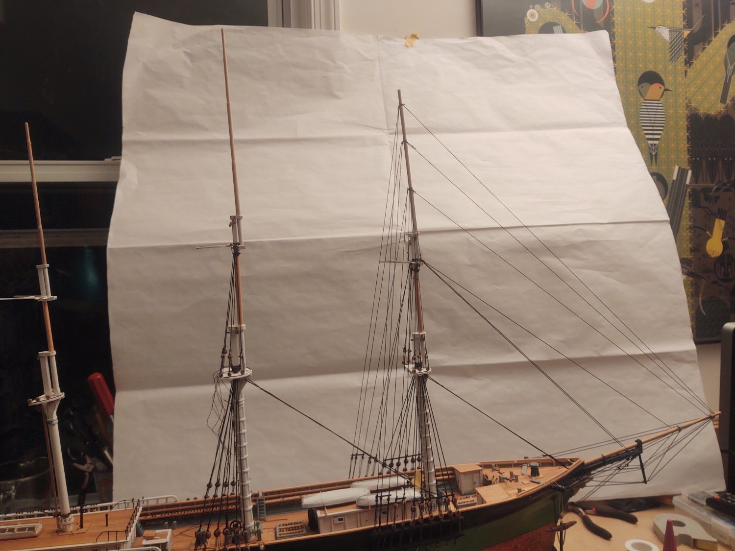
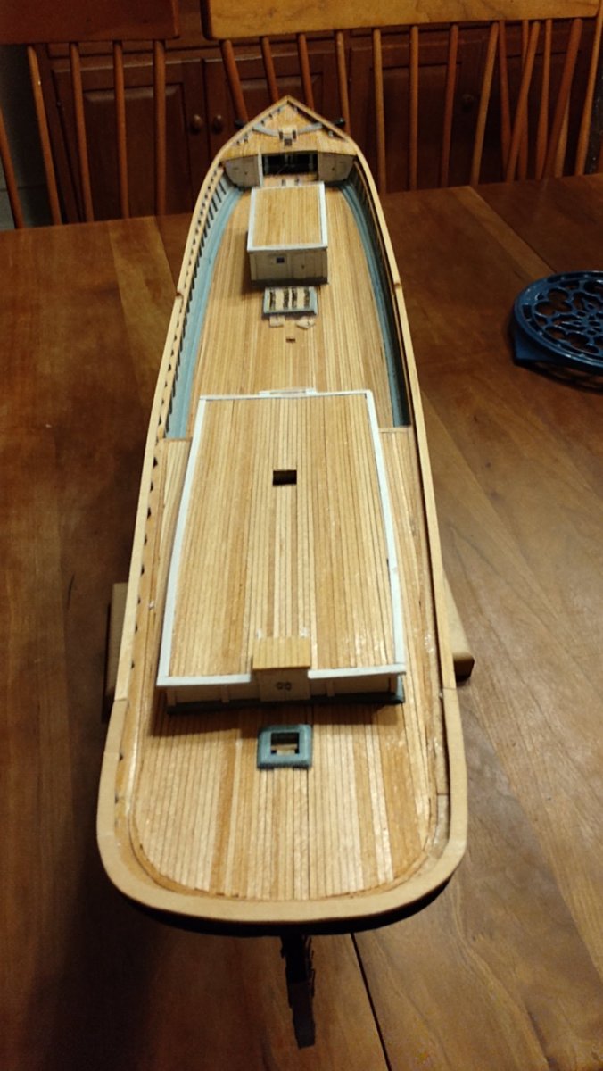
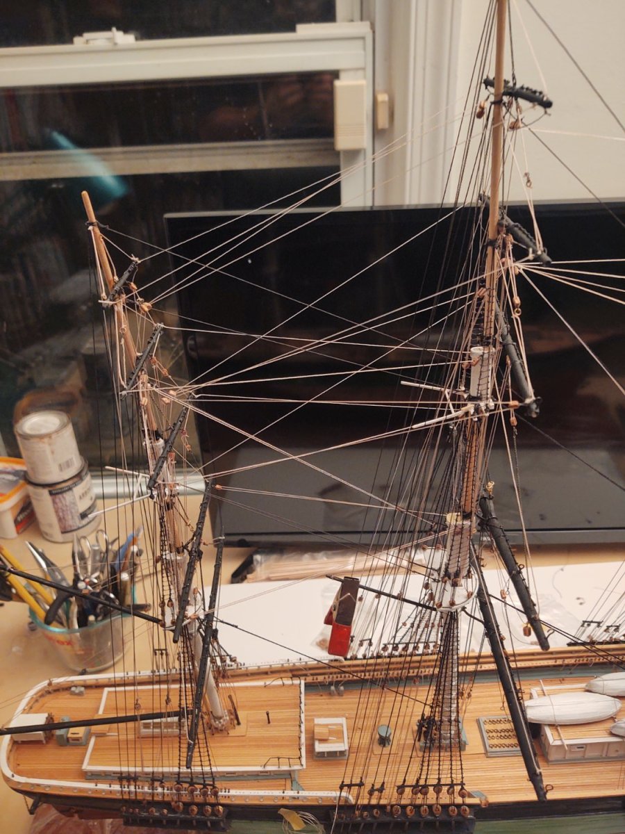
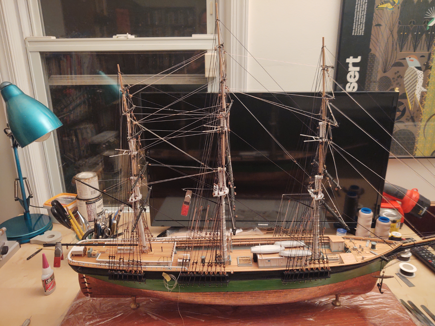
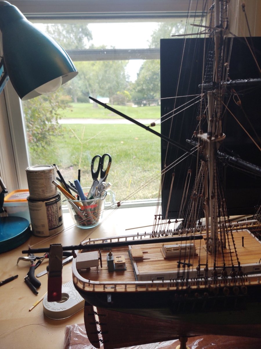
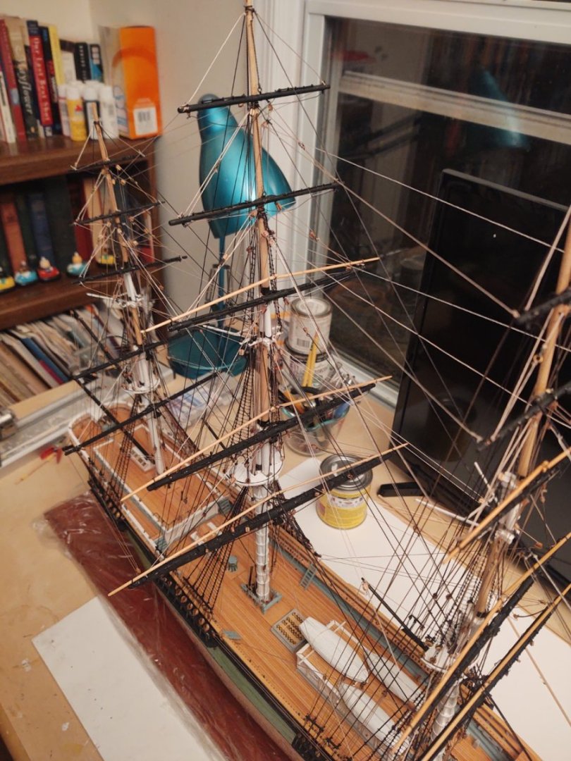
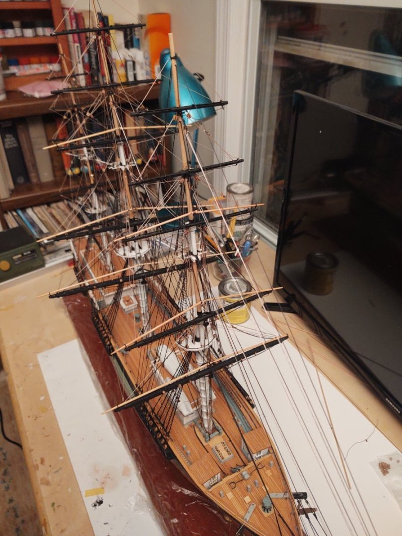
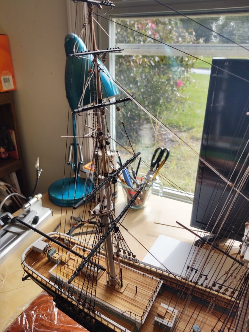
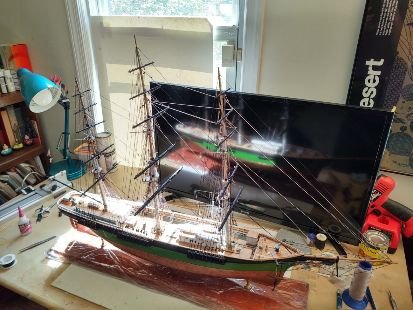
Thanks @douglaspbrown! Well, back from Boston, where I was one of many gray haired men helping move adult children. My younger daughter is out of college - she (now) works in Boston rather than goes to school there - but I have to say that many of the parents of the students moving in on that same day were alarmingly young, at least to me. We had our kids relatively late (we were both 33 and 35 when they were born), but seeing so many mid-40's parents taking their kids to college definitely makes one feel one's age. Anyway - build logs aren't supposed to be philosophical treatises, so, progress. All of the square yards are now bent; having installed the mizzen royal and skysail yards, along with their halyards and lifts. All the yard blocks are installed, including the blocks that have six of the eight clews (the ones that use tackles - the top, topgallant, and royal) with their associated lines, but not with the actual clew blocks yet. The not yet done anything with clews are the lines clogging the deck that you can sort of see in the second photo which I will deal with as I add the corresponding sheets. I've also added the remaining 4 trucks that are used as fairleads. The ship as a whole. At some point I will move this to a location more conducive of good pictures, but for now this will have to do. So, the list: mizzen yards: 5 Jib halyards: 4 lifts: 10 Jib downhauls: 4 sheets: 8 Staysail halyards: 2 clews: 8 Staysail downhauls: 2 halyards: 4 Spencer gaff: 2 1 Braces: 30 24 topping lifts: 2 1 Stun'sl booms on hull: 2 vangs: 4 2 Stun'sl booms on yards: 12 Spanker boom: 1 Davits: 4 sheets: 2 Boat tackle: 4 Spanker gaff: 1 Decals: 3 throat halyard: 2 Gilded balls on mast trucks: 3 peak halyards: 1 Fairleads on shrouds: 8 topping lifts: 2 outhaul sheets: 2 vangs: 2 ensign halyard: 1 Change: +0 (Nothing Added!) -12 (2 yards, 2 halyards, 4 fairleads, 4 lifts) Net = -12 Remaining items: 86 As always, thanks for looking in! George

- 602 replies
-
- 5
-
-
- Flying Fish
- Model Shipways
- (and 2 more)
-
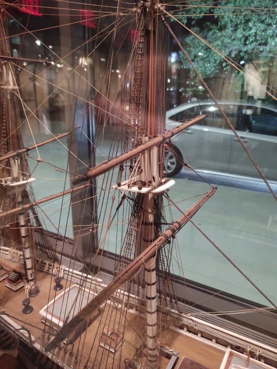
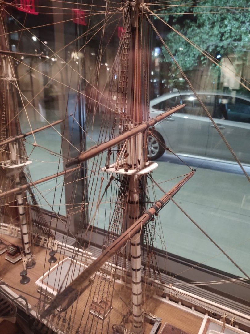
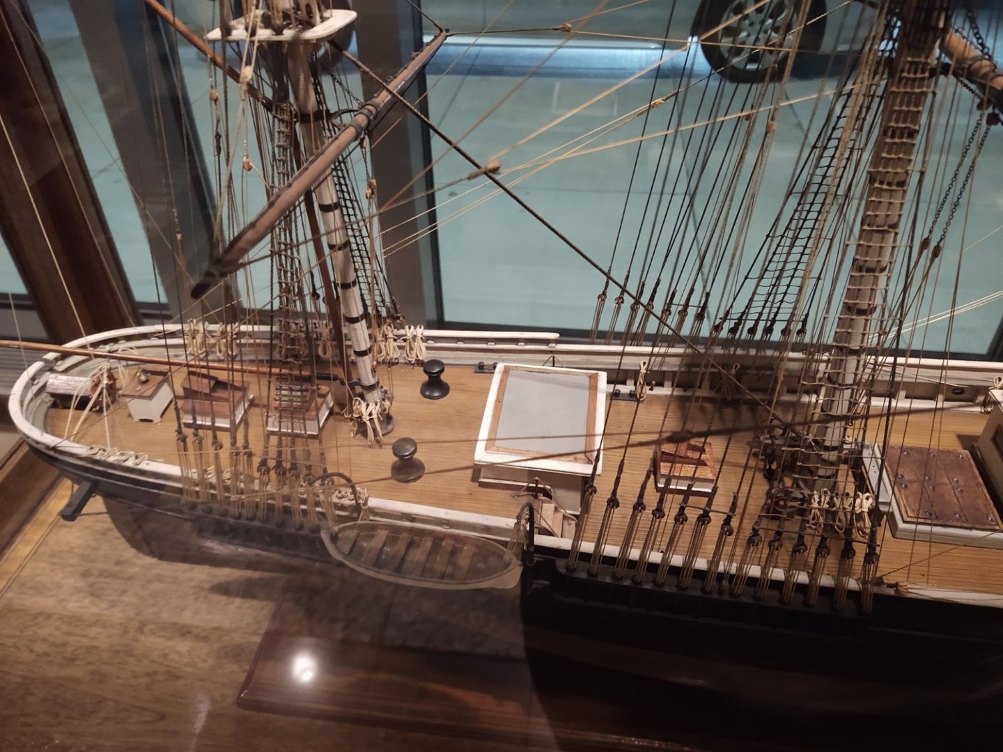
Here are a couple more It's a beautiful model. Interestingly, it is really nice looking but is rather light on the running rigging. It has the halyards, lifts and braces, and the sheets, but dispensed with the clews, staysail outhauls and halyards, bunt and leech lines and associated blocks, and the footropes. Amazing how beautiful a model you can make with just the basics.
- 602 replies
-
- 3
-

-
-
- Flying Fish
- Model Shipways
- (and 2 more)