HOLIDAY DONATION DRIVE - SUPPORT MSW - DO YOUR PART TO KEEP THIS GREAT FORUM GOING! (Only 72 donations so far out of 49,000 members - Can we at least get 100? C'mon guys!)
×
mikiek
-
Posts
2,276 -
Joined
-
Last visited
Content Type
Profiles
Forums
Gallery
Events
Everything posted by mikiek
-
 Nirvana - glad to have you along. I have been looking at the section kits for some time now, but nothing really grabbed me. I would call this one more of a chunk than a section. The level of detail is what attracted me. The whole layout is very busy. Excellent point on the laser burns. Some of that will be planked over, however a good review and sanding now would be prudent as it is only going to get harder to do that as the build goes on.
 -
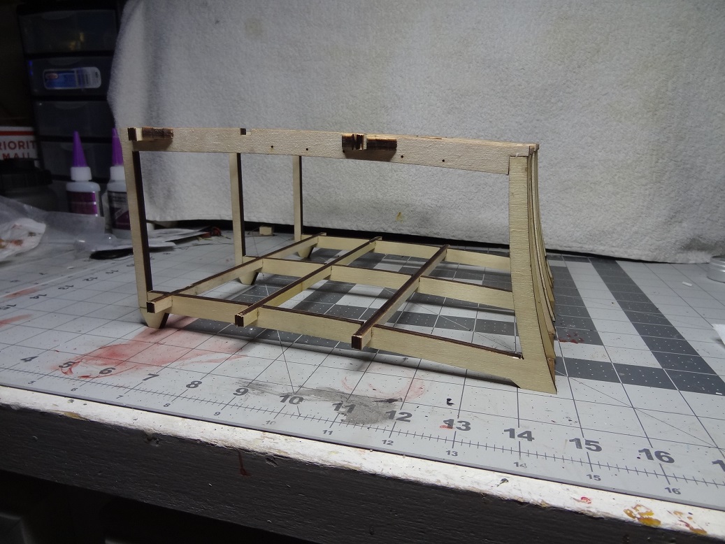
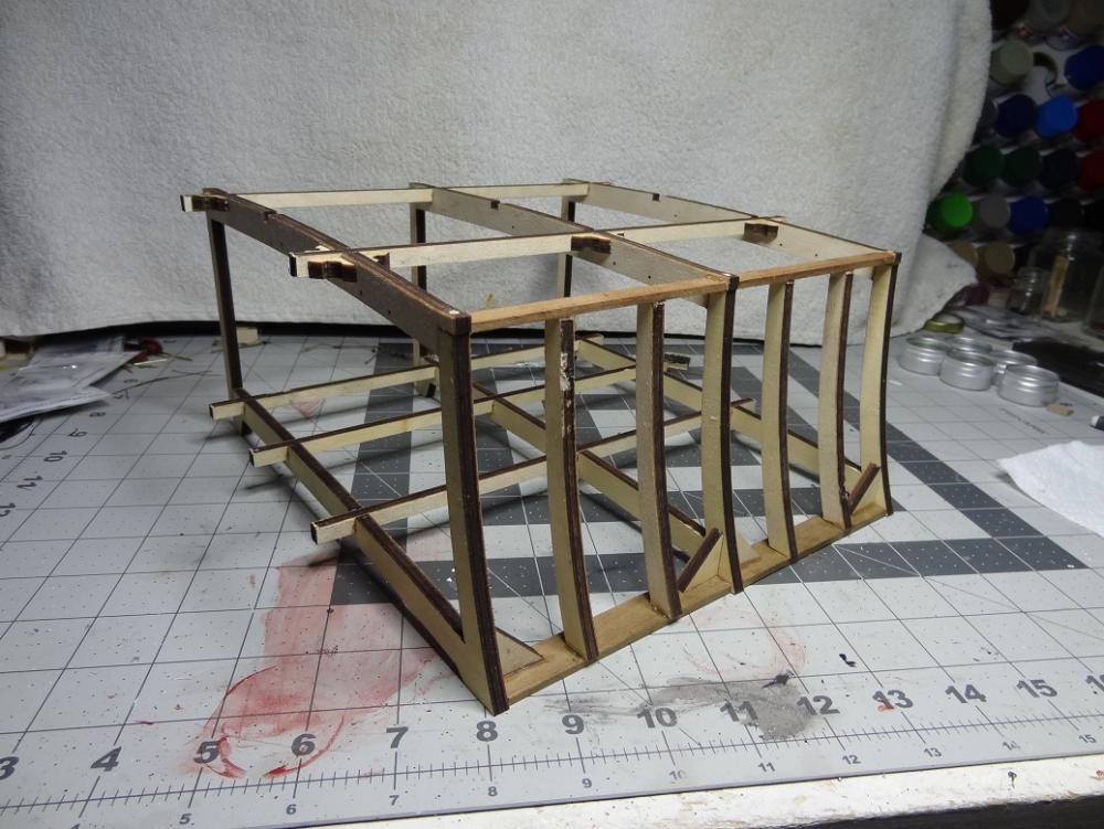
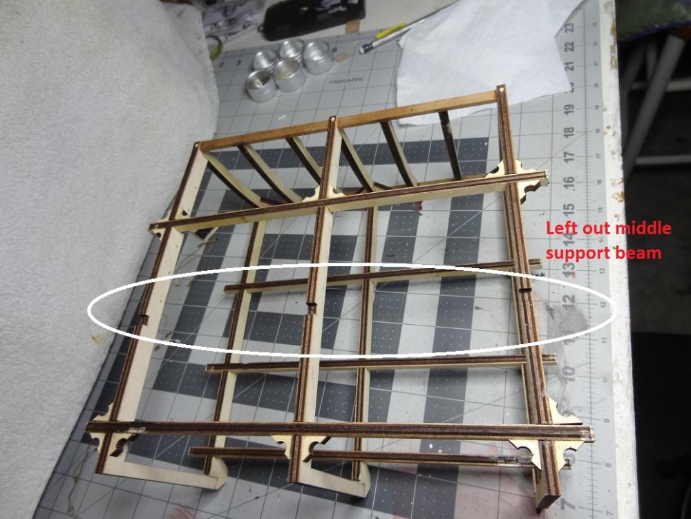
I have had this kit for a few months - on the shelf. Niagara being my main effort to this point. Watching Bob a.k.a. Cobr@ work this kit got my interest up. I am also at a stage with Niagara that is painfully monotonous, so this will be a good distraction. I don't plan on adding every gory detail to this log. Bob has done a fantastic job of that. I will make notes on what happens along the way with this build. One interesting thing already - Niagara's scale is 1:64. This kit is 1:23. Parts are huge in comparison, notably the 1 1/2" long gun barrel on Niagara is about 5" here. The kit has a lot of pieces - buckets, cannonballs, etc. that could not be replicated at 1:64. I will spare you the pix of the kit, but I will say the materials seem fairly good. The wood is well cut, brass is clean with no casting sludge on it. The one negative I have run into has to do with the laser cut parts. There are several places where the laser did not get all the way thru. Had the sheets been basswood this would be no big deal. Not sure what wood the ply sheets are but it's pretty hard and also 1/4" thick. Trying to get thru that with an Exacto has been an ordeal. I have been tempted to pull out the scroll saw as one place where the laser failed is some of the cannon carriage wheels, meaning a round cut. Next note - this is probably no biggy for most of you but as this is my second build, it is my first with plans in a non-english format. So far not a real problem as I am not paying a lot of attention to them. Most steps are pretty obvious and a look at the pix in the instruction book ( each step is described in one or two words - like 'glue') help to determine what part to use. I started putting together the frame. It was pretty flimsy at first, but Panart did a good job of providing braces/knees to beef the structure up. Each piece I add makes the whole thing a bit stronger. Here's where I'm at tonite: The gun deck is the 'ground level' deck in this build. There will also be a portion of the main deck above that. I am refraining from putting the some of the main deck supports/beams in yet. I can already see it's going to get tight trying to build the gun deck so any extra room to move hands around is a bonus.

-
A more hard core approach would be to do as was done back in the day. Cut the seizing, replace the rope, seize again. The first 2 no problem the last one - eh. Like Brian said, the eyebolt should come out without much of a fight. Worst case cut it off at the bulwark and drill a new hole right next to it.
- 648 replies
-
- 2
-

-
- niagara
- model shipways
- (and 1 more)
-
Once again, I try to make things so difficult. With those dividers I can get virtually the exact spot on both sides, which would not be the case if I drilled all the way thru. Hopefully there's nothing between the outside and inside. The kit comes with what I thought could be a lining. It's a piece of metal tube maybe 1/8". One end of it is flared. problem is there is only 1. Last I checked there is an anchor on both sides. I'm still trying to find the pic I saw that showed the wood slats as a liner. I have duplicated this, but don't yet have a hole to try it in.
- 843 replies
-
- 2
-
-
- niagara
- model shipways
- (and 2 more)
-
Good call on the breech line. Could be the pic but it seems a bit fuzzy. The rope I used also has more twist.
- 648 replies
-
- 3
-
-
- niagara
- model shipways
- (and 1 more)
-
Plans call for a protective block on the waterway. There is a slight downward groove on that. I'm thinking if I cut that groove correctly it will be my guide to go on into the bulwark. I have interesting idea for a lining. I'll take a few pix when I get back to town. Darrell, Mr Woodworker - what's the best speed for drilling a 1/8" hole into our side? Fast? Slow? Got a new Foredom a while back - it will go anywhere from barely turning to 15K rpm. I just don't want to splinter anything up. Especially when the bit comes out the hull.
- 843 replies
-
- 4
-
-
- niagara
- model shipways
- (and 2 more)
-
Just curious Darrell - with the 'false deck' under your planking, have you adjusted for that on the bulkhead frames where you will set the deck down? I guess put another way - you have raised the deck planking by the height (thickness) of the false deck when it is set down on top of the bulkhead frames.
- 648 replies
-
- 3
-
-
- niagara
- model shipways
- (and 1 more)
-
Not trying to steal your show Bob, but your fine work and great log have been enough of a push to get me started on this one. Thanks.......
- 206 replies
-
- 4
-
-
- battle station
- panart
- (and 1 more)
-
And speaking of hawse pipes - how in the world does one drill those? I mean it's easy enough to find the spot to start from but how do you get the proper angle? Do you start from the inner bulwark and drill out or the outside and drill in? I'm guessing the former as it is more important where that hole is located. Obviously the outside hole needs to be lower than the inside. I saw a pic somewhere that showed an actual lining for the hawse pipe. It was slats of wood run thru the hole with one flat side against the outer edge of the hole and the slats edge to edge in a circle. The slats were cut flush with the bulwark and hull. I haven't found anywhere on the plans where it mentions what to do after the hole is cut.
- 843 replies
-
- 4
-
-
- niagara
- model shipways
- (and 2 more)
-
many builds = many workbenches I have one of those but not the other. But seriously, my dad has been laid up for over a month now with no end in sight. I have considered taking a kit to his place and doing it with him. This might be a good candidate, especially because of the larger sized parts. Of course that means hauling my tools over there. Has the build required any odd tools or supplies? Just the usual stuff - cutting, gluing sanding? Any need for power tools or soldering?
- 206 replies
-
- 4
-
-
- battle station
- panart
- (and 1 more)
-
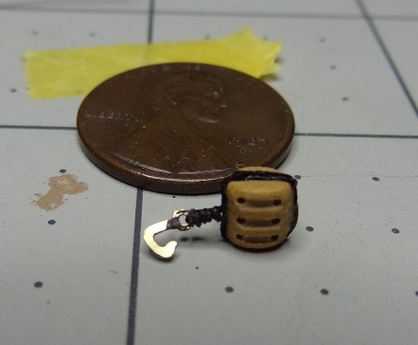
Looking over the cathead rig again last nite, I have decided it needs a slightly larger hook and anchor ring. I came across some specs stating a 1st rate ship anchor block was approximately 26" wide and the hook was 20"-24". The anchor ring is supposed to be wrapped - canvas in real life, probably rope for modeling. This would be easier to do with a bigger ring. I realize Niagara's were probably smaller than that but proportionally the hook should be almost the same size as the block width. I used a 4mm PE hook. I think it needs to be a little beefier. I started making some hooks from wire last nite but have not yet come up with the right size yet. Will work on this more tonite. I have not reviewed the general rigging plans in detail yet but I got to wondering how widespread the use of stropped hooks are in that application.
- 843 replies
-
- 5
-
-
- niagara
- model shipways
- (and 2 more)
-
If you don't have some already, a craft/hobby store has beads small enough. That's where I got mine. The package had brown & black beads of several sizes & shapes.
- 287 replies
-
- 3
-
-
- niagara
- Model Shipways
- (and 1 more)
-
Thanks everyone for the comments. I have the extra bit of rail installed. I was missing a cleat behind it for lashing. As far as stowing, I was trying to decide whether to leave the cable clinched or not. I suppose that a Captains call. I don't recall what the plans say about what to do with the cable that comes inboard thru the hawser. I would assume it goes below deck pretty quick but not sure where. I have too much rope in the tackle, but that made me wonder how much is enough? If I understand the weighing process, the cable is being hauled in via the messenger and capstan. At this point the cable is going directly thru the hawser (cathead not involved)? When the ring breaks the water surface, it is doing so below the hawser, not the cathead. Catting then hooks the cat block to the ring. If yes, then the cat block needs to be able to extend to about water level in front of the hawser? I may sound like I'm knit-picking but there is not a lot of space to put extra rope from the tackle. Plans say to belay rope to pins in cathead base but the pins are not long enough to wrap much rope. Will probably pull those and use some longer ones. Assuming the block is extended far enough to reach the ring, how much rope is required on the hauling end? Is he overthinking this one?
- 843 replies
-
- 4
-
-
- niagara
- model shipways
- (and 2 more)
-
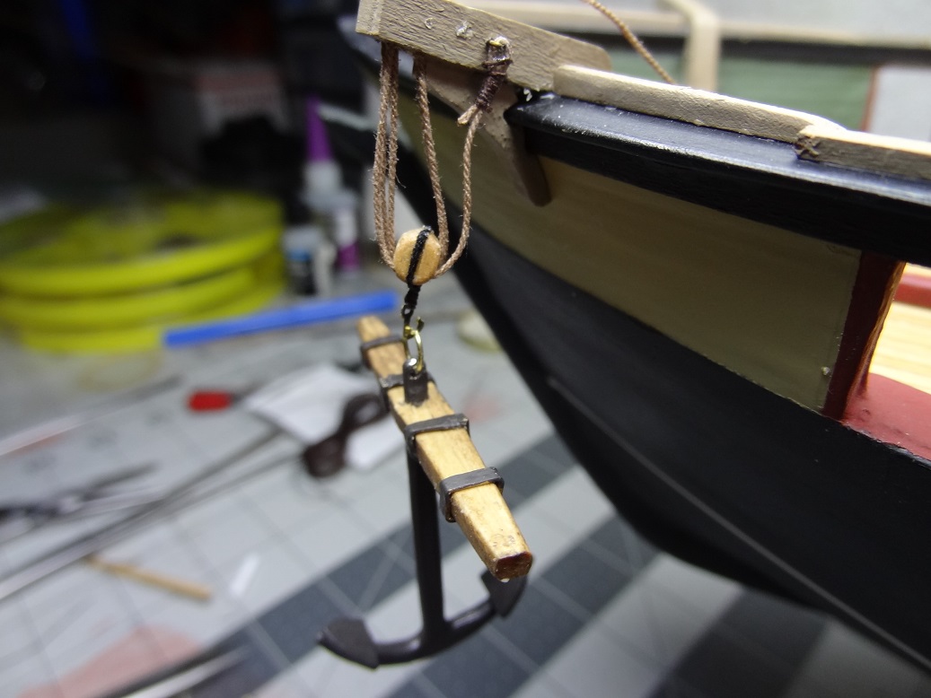
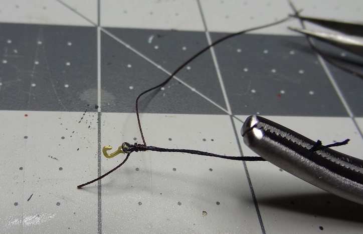
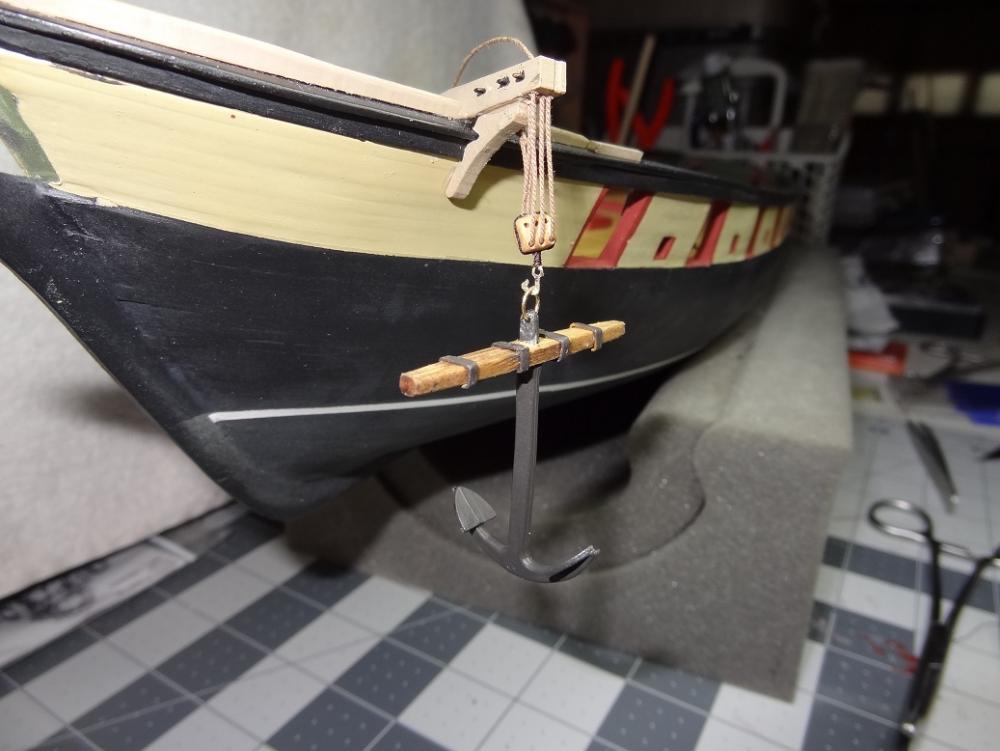
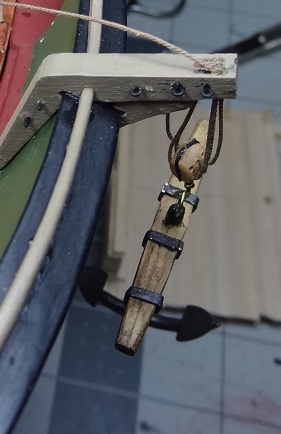
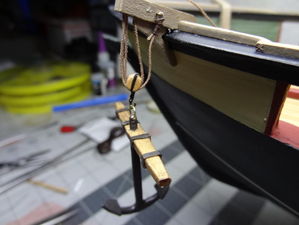
Finally something finished - or at least 1 of 2. The cathead assembly with anchors. It's funny how some days you "got it" and some days you don't. I wasted an entire evening trying to make brass collars for the anchor stocks. For crying out loud, it's just a rectangle (4 corners) from brass strip. Couldn't make one if my life depended on it. Some not square. Some too big. Some too small. Right size but too much solder. Next nite, cranked out all 8 in about an hour. Go figure. Did a few basic rigging things - seizing, stropping hooks to blocks. Really makes me wonder if I have the patience for the real rigging job coming up. Maybe Niagara becomes an Admiralty style build The research for this was interesting. How anchors are laid and taken in. I forgot about a couple of books I had on basic seamanship and life on board. Both had good write ups on anchors and dealing with them. "Seamanship in the Age of Sail" - John Harland and "Nelson's Navy" - Brian Lavery. I'm not sure I would call them "must haves" but I will say there is some fascinating information in both. And on with the show: Seizing a hook. I cheated here. Just glued the seizing cord to what will be the stropping rope, wrapped a few times and glued the other end. I had always wondered where the triple block was used. Anchor and cathead with cat block assembly A few minor steps left. Wrap the anchor ring. Touch up the paint. Decide how to stow the anchor - the books show several different ways.

- 843 replies
-
- 3
-
-
- niagara
- model shipways
- (and 2 more)
-
Haven't had to do what you are questioning yet. The first thing I am going to try is getting the 2 lateral and 1 rear breach tackle tight. That, in addition to the pin in front will go a long way to keep them from moving - at least along the plane of the deck. That assumes no more turning the hull upside down. If that isn't enough, the next thing will be a spot of glue under the carriage at the hole for the pin. Either that or epoxy on the pin before setting the carriage on it. I would try to limit how many places are glued in case you have/want to move them in the future.
- 648 replies
-
- 2
-
-
- niagara
- model shipways
- (and 1 more)
-
Welcome back. You're leading the way on rigging. I'm sure someone in the know will jump in.
- 287 replies
-
- 4
-
-
- niagara
- Model Shipways
- (and 1 more)
-
You know I just remembered I have a serving machine gathering dust in a cabinet. Those can be used for seizing as well as serving. I'm getting tired of all my digressions but that might be worth trying. It does seizing very well, but it takes some time to get everything into position. Something else to do tonite........
- 648 replies
-
- 3
-
-
- niagara
- model shipways
- (and 1 more)
-
Darrell - are you still using the premade seizing? If yes, how do you thread the rope thru the seizing?
- 648 replies
-
- 3
-
-
- niagara
- model shipways
- (and 1 more)
-
Two things I noticed while fixing the catheads: 1. The support knee extends a little too far outwards and actually covers some of the holes drilled for the sheaves. 2. With the Ch in place, all of a sudden you have to be a lot more careful about setting the hull down. You can't set it upside down anymore either. I imagine I will be breaking them a few times, kinda like the bulkhead timberheads before they were planked over.
- 843 replies
-
- 1
-
-
- niagara
- model shipways
- (and 2 more)
-
This one is on my shelf. Thanks for continuing with it and letting us have a peek.
-
I should have thought about that book. It has just about everything else. Nelson's Navy also has a good segment on weighing anchor but only mentions guiding the cat block with lines. I forget how much information those 2 books have. I'll bet they send the "new guy" over the side Thanks for chasing that down.
- 843 replies
-
- 1
-
-
- niagara
- model shipways
- (and 2 more)
-
I'm posting this here mainly because it has to do with the metal parts I glue to my build. Everyone seems to say epoxy is the best choice for metal to wood. I won't argue with that. What I really dislike is going to the trouble of mixing up the 2 parts for what is often times just a few pieces. Most of what is mixed is either thrown out or dries too quickly in the mixing cup. I'd love to find something in a tube or bottle that could be squirted or applied with a toothpick. Am I dreaming?