
HOLIDAY DONATION DRIVE - SUPPORT MSW - DO YOUR PART TO KEEP THIS GREAT FORUM GOING! (Only 24 donations so far out of 49,000 members - C'mon guys!)
×


mbp521
-
Posts
1,003 -
Joined
-
Last visited
Content Type
Profiles
Forums
Gallery
Events
Everything posted by mbp521
-
 John, I found it easier to blacken the entire 24" strip first then cut it into 3" (in my case 5") sections. Once cut, all I had to do was to blacken the one end to mate up with the next board in line. It's just my opinion, but since you are going to stain/varnish the deck, it looks much more realistic to have the variations in color than to have them all look the same. These variations would occur naturally with the timbers used for planking from the different trees anyway. To help with hiding the area that was not planked, I painted the deck black inside. Most of it is hidden by the boiler but I also built up some simulated crates to screen the emptiness of the machinery room. I also printed out a couple of steam engine pictures and glued them to black foam board and mounted them in the engine room. This is barely visible though the wall grate, but I thought it was a neat touch. Just throwing some ideas out there. It all depend on how far you want to take your details. That's the good thing about this kit, it leaves you open to throw as much or as little detail into it as you want. All in all, your planking is progressing nicely, and looking great! It is a pain to do, but definitely worth it. -Brian
- 157 replies
-
- 1
-

-
- chaperon
- Model Shipways
- (and 1 more)
-
Wooohooo! Another Cairo build and another Cathead log. Really looking forward to following along on this journey. Glad to see you back at the bench again Eric. -Brian
- 113 replies
-
- 4
-
-
- Cairo
- BlueJacket Shipcrafters
- (and 1 more)
-
I had to ask. With all the other small detailed metal bits that you made, I wasn't sure. -Brian
-
Tom, I'm a little late to the party, I just happened to stumbled across this beautiful build the other day and have been reading through. I purchased this kit a few months ago, and hopefully will have it on the bench soon. Thanks for putting together this log and pointing out all the gotchas and pain points. I'm definitely following along the rest of the way. -Brian
- 163 replies
-
- 1
-
-
- Model Shipways
- Constitution
- (and 2 more)
-
Hard to say what the plank length was on the actual Chaperon, if I’m not mistaken I went with 20’ planks myself. I think the Chaperon, like many others had her decks painted to protect against weathering, so if you were to look at the pictures of her there would be no way to tell what length they were. I chose not to paint my deck, just leaving the natural wood color. This is something that I have done on all of my ship models so far. Although not authentic, I like the way the natural deck looks. -Brian
- 157 replies
-
- 2
-
-
- chaperon
- Model Shipways
- (and 1 more)
-
Guilty. John, it is a very long and drawn out process to plank the decks and carve out all the notches, but it will be worth it. Once you are done, I think you’ll be very happy with the results and glad you did the extra work. That finger joint was my biggest gripe about the kit. I understand that it was done due to packaging and cost limitations, but I’m sure there could be a better way to go about it. Your Chaperon is coming along very nicely! -Brian
- 157 replies
-
- 1
-
-
- chaperon
- Model Shipways
- (and 1 more)
-
Interesting article George. There was a lot of litigation and controversy surrounding the bridge in the beginning. Seems like there still is a bit of controversy as well, with people not knowing how to read road signs. Especially the instances where several busses have tried crossing it with clearly marked signage and height barriers. I haven't looked into it, but I wonder if the bridges construction led to the steamboats having to redesign their smokestacks with hinges to clear the bridge. -Brian
-
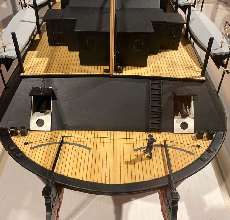
I see what you are referring to now. I actually didn't notice that until now, thank you for pointing that out. I didn't use this model as a reference too much for my research, since there are several inaccuracies with it, but It would make sense to have the doors in that configuration with the smaller guns back there. There were several "executive decisions" that I made throughout this build due to lack of information. Many of the decisions I based on the photographs or additional documented information of the sister ships, especially the Cincinnati and Mound City since they were all built in the same shipyard in Mound City. These boats were designed for frontal assaults, this was the reason for all the big guns to be located in the forward position and the reinforced forward casement. I read somewhere (I forget the reference, it might have been in the "Hardluck Ironclad") where someone had stated that Cdr. Selfridge had the Cairo's guns arranged in an unusual configuration. I do not recall the reasoning behind it, but strategically it made sense, and she was setup quite differently than her sisters were. -Brian
- 739 replies
-
- 13
-
-
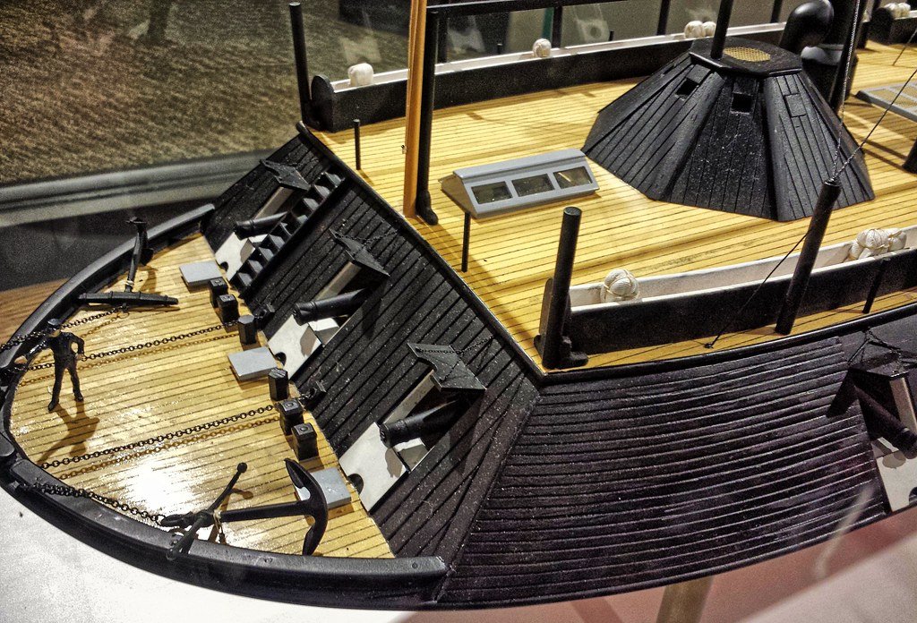
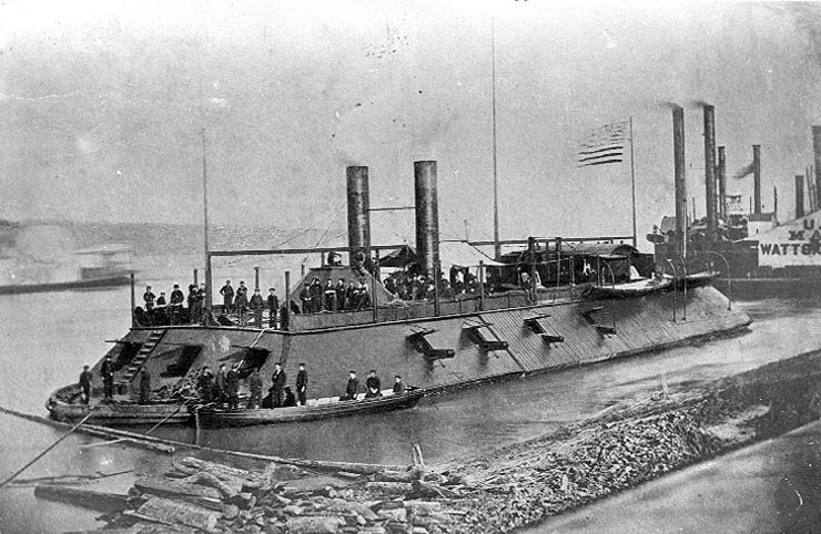
Leiste, I'm not real sure of which model you are referring to, The Cairo museum only has two models on display, one which is a representation of the current display outdoors showing the cradle and the existing original fabric. This model, like the actual boat does not have the forward gun port doors on it. The other model is complete boat with the side cutaway, and it does have the forward gun port doors pierced on the upper and lower sections. In the contemporary photo of the Cairo, you can see that the forward gun port door were pierced on the tops and bottoms. Only the Port and Starboard #3 & #4 gun port doors were pierced on the lower section only. This was the location of four of the smaller 32lb guns. As for the aft gun ports, it is hard to tell if they were pierced on the top and bottom or just the bottom, since there are no photographs of this are on the original boat, bit they were also smaller guns (32 pounder and 30lb Parrot) and could have been pierced on the bottom only. I just went with the photos of her sister ships that have the aft gun port doors pierced top and bottom. -Brian
- 739 replies
-
- 11
-
-
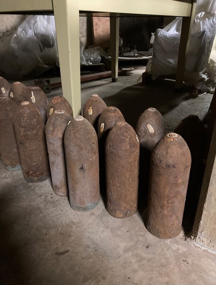
Lieste, Thank you for the specification on the munitions. I totally agree that the Parrot would have most likely not used round shot. At the time I made up the ammo crates I wasn't thinking that much of this would have been seen and didn't put too much focus into the interior details in this area. As the build progressed, I started focusing more on the details but eventually this area got covered up and it was too late to go back and change. Unfortunately this area still cannot be seen. This past May I had the opportunity to see first hand the actual ammunition that Cairo carried and you are correct, they did indeed use ogive shot in the 30lb Parrot. These are some of the 30lb Parrot rounds recovered from the wreck. -Brian
-
Johnny, Thank you for the very useful info. I've got a feeling that this will most likely be the route that I take on the construction of the intermediate link. Still researching, but it seems to be the most reasonable solution. Roger, I totally agree with the turnbuckle. I would think that over time the hemp rope would stretch causing the rudders to get out of alignment, or bending of the tillers for that matter, making adjustments necessary. Turnbuckles on the intermediate link and internally on the control lines would help with the adjustments. Mark, I was thinking the same thing. Wire rope could also cause some wear and tear on the hawse pipe as well. Similar to what I mentioned previously with the chain theory. Thank you all for the valuable input. -Brian
-
Thank you Roger for the additional input. It truly helps give me some direction. An executive decision is most likely what I will be doing here, it definitely wouldn’t be the first time. I’m still doing a little digging to see if I can turn something up that can confirm my suspicions. At the moment I am seriously leaning towards the solid rod for the intermediate link and hemp rope for the control lines, I just want to make sure that I do my due diligence first. I wasn’t aware that Eades had built a suspension bridge in WVA, most of the research I’ve done on him focused on his bridge in St. Louis, I guess since it is the one still standing. The man definitely had his hands in a lot of projects. You definitely bring up a good point on the hog “chain” theory. I hadn’t even thought about that. I’ll also need to keep that in mind while researching to make sure that I am clear on the specifics of the reference. As for her being a riverboat, Cairo’s (and her sisters) hull design was not new, they were based on Sam Pook’s existing hulls for some of his earlier boats, and that is what I am researching right now to see if any of these boats have a similar steering system. So far I haven’t found much, but I’m still looking. -Brian
-
You are correct, the area on the fantail was exposed, as were all control lines from the hawse pipe to the tillers. They were susceptible the elements and enemy fire. After reading the comments above, I got to thinking even more about this. I am not so sure that what I thought was wire cable in my initial post, could have not actually been an iron connecting bar that got bent during the salvage. An iron connecting bar makes better sense given the pressure of the water and the push pull action on both rudders. Like you said earlier, even severing one side of the control line would disable the steering functionality regardless of the makeup of the intermediate link between the tillers. This also got me to wondering about the control lines to the ships wheel. If the exposed area was actually chain, how much wear and tear on the hawse pipe would that cause? Seems to me that the constant steering adjustments made when the ship was under way would cause significant rubbing and wear in this area creating frequent maintenance problems. It would also seem that if it were chain, it would have still been attached when they pulled that section up from the river. In the salvage video, there is no sign of chain or linkage where this would have been attached on the tiller. This leads me to believe that the outboard control lines were hemp rope that had rotted away. -Brian
-
Amazing work as always Keith. Do you have a current shot of what she looks like now, or did I overlook one in a previous post? -Brian
-
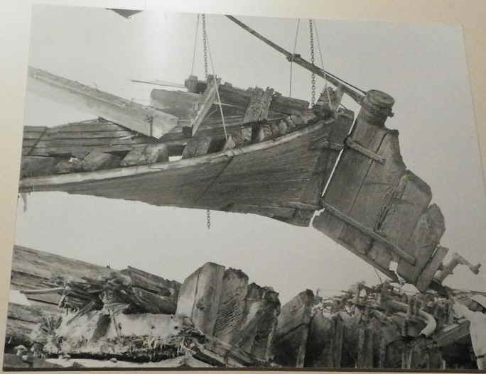
Eric, I am assuming you are talking about this semi-circular feature here. If so, that is the tail of the lifting cable that is looped through the shackle. I had to go back and re-watch the video to be sure. In that picture it does look a bit odd since it somewhat blends in with the shore in the background. The tiller is actually still attached to the top of the rudder. Here is another photo that shows it from a different angle when they were offloading the piece from the barge at Ingalls Shipyard. Unfortunately, the cable cannot be seen in this photo and could have been removed during transport or just not shown, and the chains in this picture are part of the lifting sling. Mark, indeed this is a deep rabbit hole. Now you and Eric have really got me to thinking even more. I am now wondering if the control lines from the wheel to the outboard sides of the tiller was made from hemp rope and the connecting line between them was wire cable. This would explain the absence of the rope on the outboard side of the tillers, as it could have rotted away and the presence of the cable on the inboard side of the tillers would indicate that they were made from two different materials. That is a great question, but unfortunately this is the only City Class gunboat in existence, and of the remaining Ironclads (3) none of them had any of the stern section recovered and none had a similar style of steering system. I am going to have to see if I can dredge up some info on other Ironclads that had this type of steering system and see what was used on them. And the search continues. -Brian
-
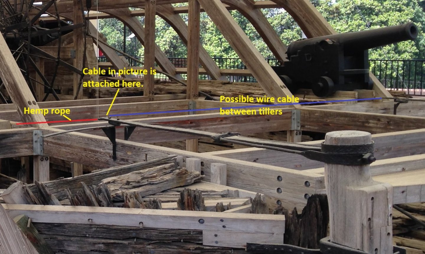
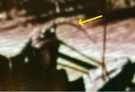
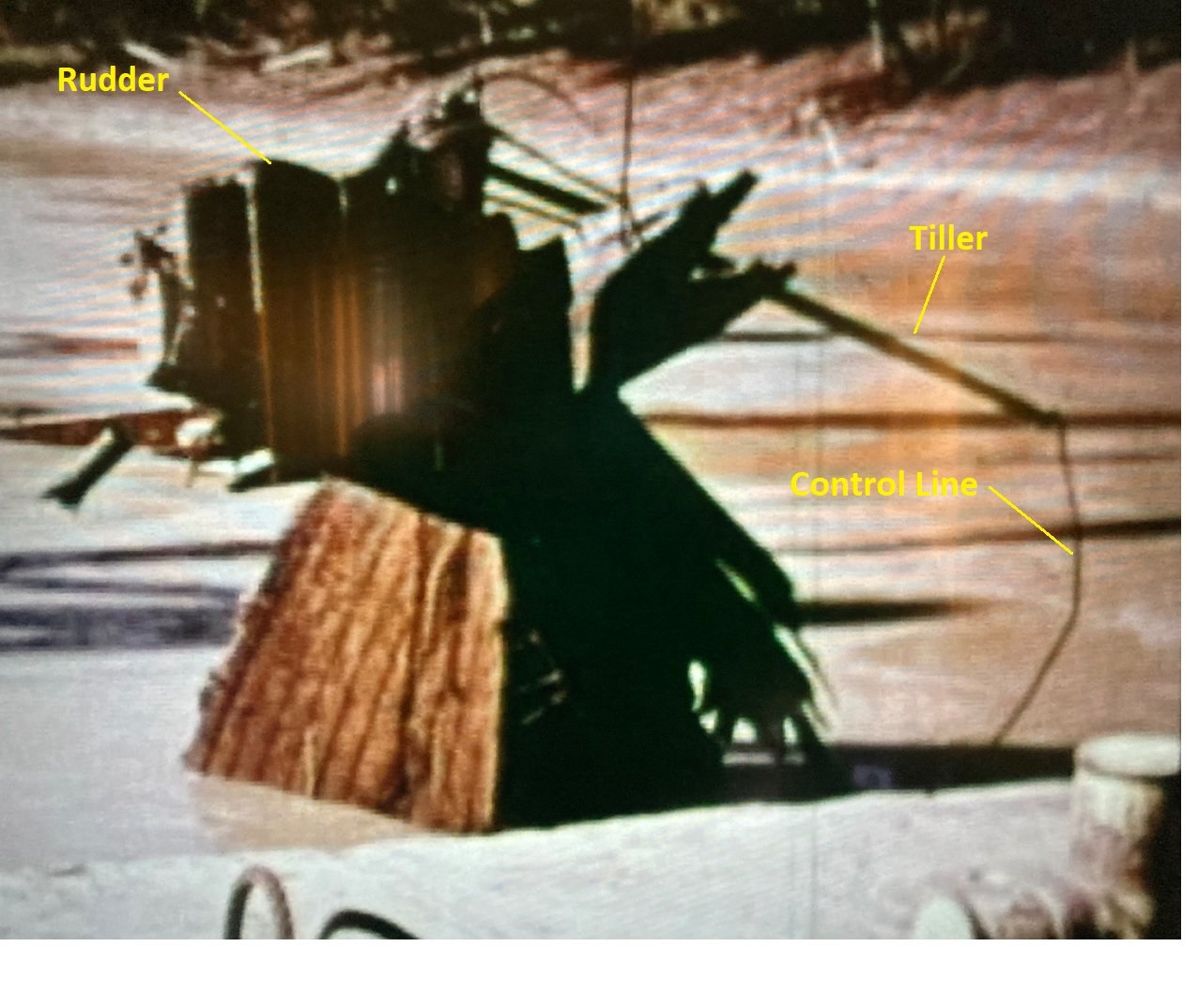
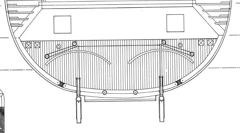
Greetings everyone, I have hit a snag on my build and wanted to throw this out there to see if I could get an opinion from the experts to help me out. I am fast approaching the installation of my rudders and have been doing a considerable amount of research on how they were controlled. On the City-Class gunboats, the pilot house was mounted on the hurricane deck housing the ships wheel. The control ropes for the rudder tillers ran through the gun deck, most likely along the roof beams toward the aft casement, where they dropped down to deck level and through the casement just above the deck. They were then rigged through another series of pullies on the fantail where they were attached to each of the rudder tillers on the outboard sides. There was also a connection between each of the tillers on the inboard sides of each one to keep them aligned. I have read several stories of where sharpshooters would target these exposed control lines for the rudders in an effort to disable to boats and make them easier targets. I have also read, and had several discussions that conflict on what the makeup of the control lines were. They have been referred to as rudder ropes, rudder chains, rudder cables and rudder lines in several documents which makes it difficult to determine what they used. I have also read references that they may have had some sort of hybrid makeup where the control lines from the ships wheel to the aft casement were made of rope. They were then tied to chains which ran through the casement, around the pullies and attached to the tiller. But through my research, the majority of the accounts say that the exposed control lines were chain. Some of my thoughts on this were that if the control lines were made from rope the entire length, they could have easily been severed by a well-placed shot. If the control lines were made up of chain, it seems like it would have been a little harder to take out the control lines with a mini-ball. Not saying it would be impossible, just a little tougher. The chain option could have also been a retrofit after several rope lines were severed. Seems that retrofitting happened a lot with these boats. This brings me to the theory that the control lines could have been made up of wire rope, or steel cable. Wire rope had its beginnings in the early 1830’s Europe and was primarily used for elevators and cranes, but not widely used for much more. I have also been having trouble trying to find any information on when steel cable was incorporated into marine usage, but I am pretty sure it could have been during the mid 19th century. However, I managed to get my hands on the salvage video of the Cairo and stumbled across an interesting shot that helps prove my cable theory. In the below snapshot from the video (apologies for the graininess, it’s hard to take a picture of a TV screen and have it come out clear), it shows the Port rudder being pulled from the Yazoo River, and if you look closely, you can see what appears to be a wire rope (steel cable) attached to the tiller on the right side of the shot. The reason that I believe this is a wire rope is due to the kink in the middle, between the tiller and the waters surface. Seems to me that chain would hang straight down as would regular rope. It would also seem that you would be able to see the links in the chain or at least it wouldn’t have as smooth of features if the chain was caked with mud blocking the links. Anyway, I was hoping to get some opinions on my theory that the rudders were controlled on the Cairo by wire rope and not chain or regular rope, before proceeding with my rudder installation. As always, thank you for stopping by. -Brian
-
The bikers are usually there on the weekends. It supposed to be nice here Saturday so I’m sure they will be there. -Brian
-
Stéphane, mon français est un peu rouillé, ça fait plus de 40 ans que je l'ai pris à l'école. Cependant, avec l'aide de Google Translate, je peux peut-être réussir. Merci beaucoup pour les gentils commentaires. Je suis heureux que certains de mes conseils aient été utiles et je suis toujours heureux de les partager. I hope I got that right. -Brian
-
@Keith BlackHere you go Keith, thought you might like this. From the booming town of Tioga. -Brian
-
Glad to help out. If you follow the below link there are several contemporary photos of the Chaperon in her hey day. The link is to the University of Wisconsin - Madison La Crosse and they have an excellent collection of old photographs of not just the Chaperon, but numerous other steamboats, Some of these photos also show many of the changes Chaperon had through her career and a couple of them from back when she was the JC Kerr. If I am not mistaken, in some of the photos you can see the changes the area in question above went through over time. If anything, the old pictures are neat to look at. https://search.library.wisc.edu/search/digital?q=chaperon&filter[facets][collections_facet~Historic+Steamboat+Photographs]=yes -Brian
- 157 replies
-
- 1
-
-
- chaperon
- Model Shipways
- (and 1 more)
-
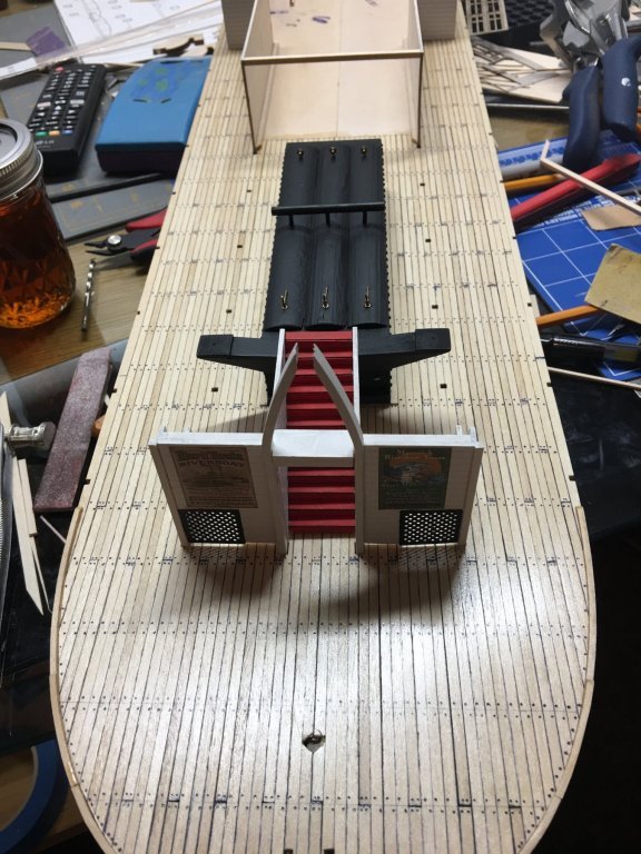
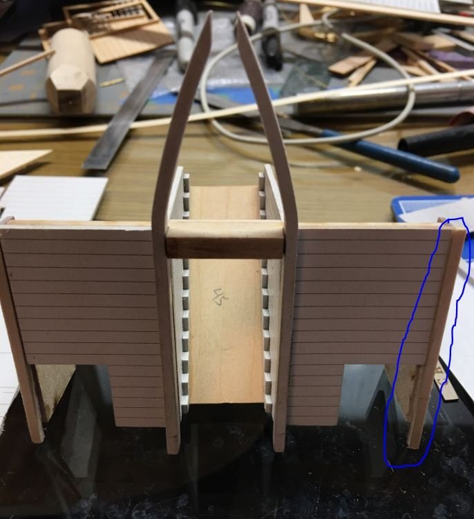
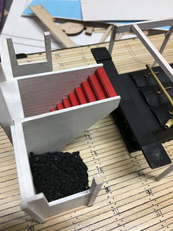
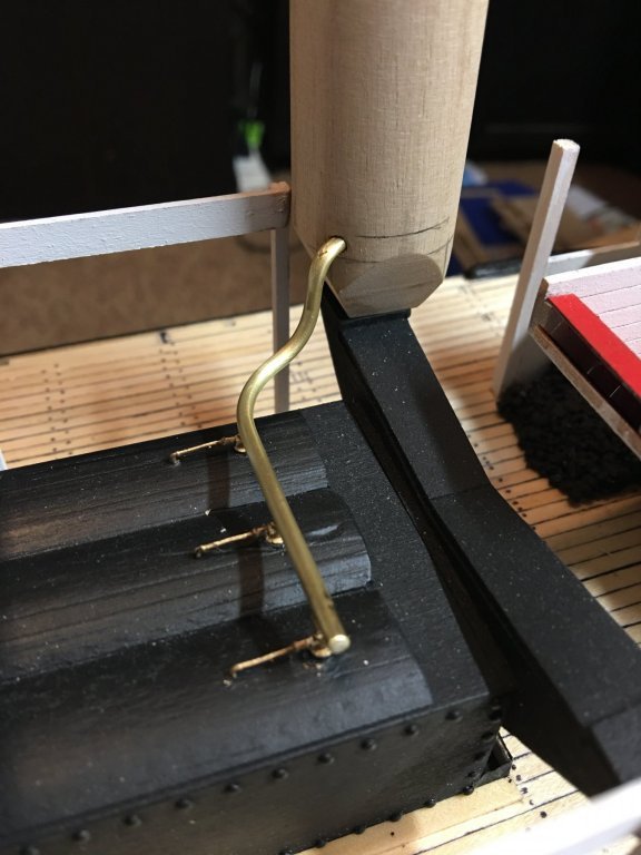
John, Eric has described it correctly and should be installed per the drawing and his instructions in the above post #42 from your log. There is a gotcha in there though, before you glue the corner strips in, align the pieces 37P/S up with the holes in the deck to make sure they go in properly. You can reference entry #11 on page 1 of my build log to see how I assembled everything and the trouble I had getting it all together. The picture that Eric provided is after the installation, entry #45 and entry #41 is the installation These are on page 2 of my build. I also posted the pictures below, but the build describes the process a little better. Also, when you get to this point, here is the way that I built the vent pipe for the safety valves. I formed it up before installing the hurricane deck since it was a lot easier to access. Once the deck was installed I came back and installed the pipe. It was still a little tricky, but it was a whole lot easier without the deck in place. Hope this helps. -Brian
- 157 replies
-
- 1
-
-
- chaperon
- Model Shipways
- (and 1 more)
-
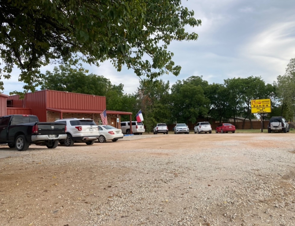
All of these small towns are starting to grow. Everyone wants to get out of the Metro-mess. Love Clark’s Outpost. Eat there pretty regularly. They actually burned down about five years ago. Took them a couple of years to get back up and running in their new building, but they are still just as good. -Brian

