
HOLIDAY DONATION DRIVE - SUPPORT MSW - DO YOUR PART TO KEEP THIS GREAT FORUM GOING!
×


mbp521
-
Posts
1,002 -
Joined
-
Last visited
Content Type
Profiles
Forums
Gallery
Events
Everything posted by mbp521
-
 Man Keith, even with your quick builds your work is remarkable. I’m sure she’ll be more than happy with her gift. -Brian
 -
Thank you John, I appreciate the nice comments. The LED’s that I used are the multi resistor, micro led’s that I purchased off of Amazon. I used the Golden Yellow color since I thought it represented the coal oil lamp light the best. If I remember correctly, I have about 25 of these installed and they are all powered by a single 9v battery. The link to them is below. Micro LED's I look forward to following your build. -Brian
-
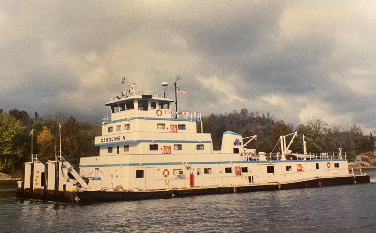
Thank you Roger. She was built by the Jeffboat Company in Jefferson, IN. She was originally laid down as the Louis H. Meece in 1973. She was later renamed the Caroline N. after my friends wife was born. When my friends father in law retired, he sold the company to Marquette Transportation out of Paducah, KY and she was renamed again. Not sure what the new name is just yet. Haven't gotten that far into my research yet. Hopefully I'll know more by the time I start my build log. -Brian
-
Thank you Eric for the kind words. The towboat was not in my original plans, I wanted to start another scratch build of the City of Baton Rouge Ferry, but when my friend approached me about the towboat, I thought why not. To top it off he offered to pay me for it, and wasn't taking no for an answer, so here we go. I still have about six new kits sitting in my closet, two partial builds that I need to finish and the NRG Capstan project that I have to do as well. Looks like I have the next several years planned out for me. Hopefully my towboat project will help you out when you get around to that one. As for swinging by on your Oklahoma road trip, no need to beg, my door is always open and we enjoy entertaining company. -Brian
-
Thank you all for the kind words. Keith, after a short break, I will be stepping outside of my comfort zone a bit and into the 20th century. A good friend of mine asked me to build a model of a Mississippi River towboat that was owned by his father-in-law. His father-in-law named the boat the Caroline N. after his daughter (my friends wife). He wants me to build it as a birthday/anniversary/Christmas gift, whenever I can get it completed. It should be interesting, since I have never built a modern boat before. We'll see how this one goes. I'll definitely be doing a log for it though. -Brian
-
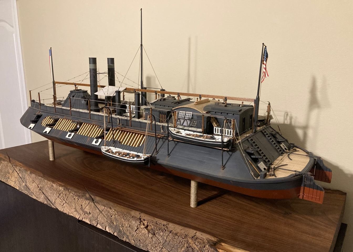
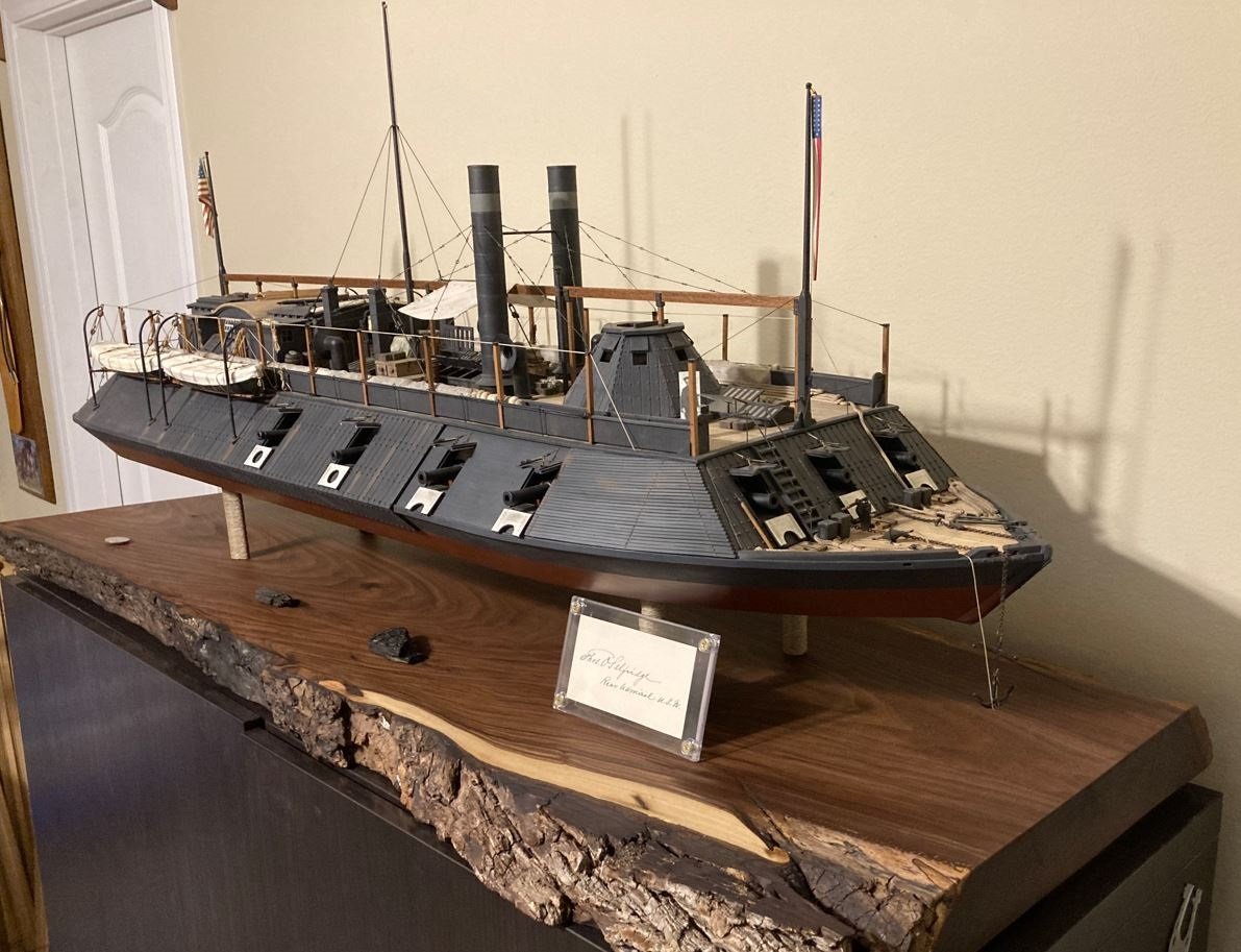
Eberhard, there are still a couple of items that I need to add to the display. One is the data plaque that I am having engraved for it, the other is a mirror to go under the paddlewheel. I put so much work and detail into the building the paddlewheel that it was a shame to hide it. It is almost impossible to see it through the cutaway, so I decided that I would elevate the model from the base and place a small mirror under it. When the lights are on, it should highlight the paddlewheel nicely. If you notice, there is a coin located on the starboard aft of the base. This is a US Quarter for the Vicksburg NMP. The quarters obverse has a depiction of the USS Cairo on it, and I thought it was a nice addition to the display. The Quarter also functions as the switch to turn on the internal lighting of the boat. Once I get these other items completed, I'll get more pictures posted. -Brian
-
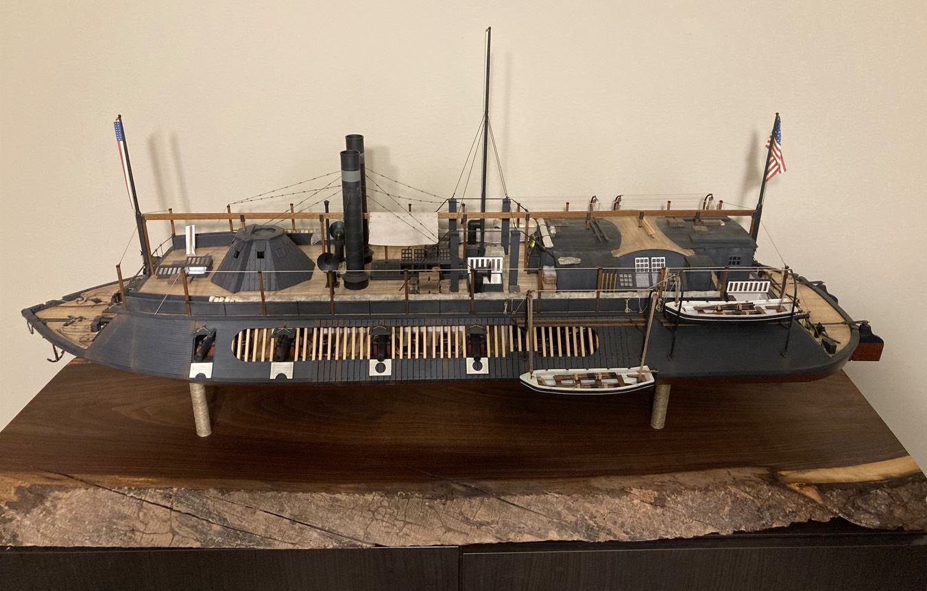
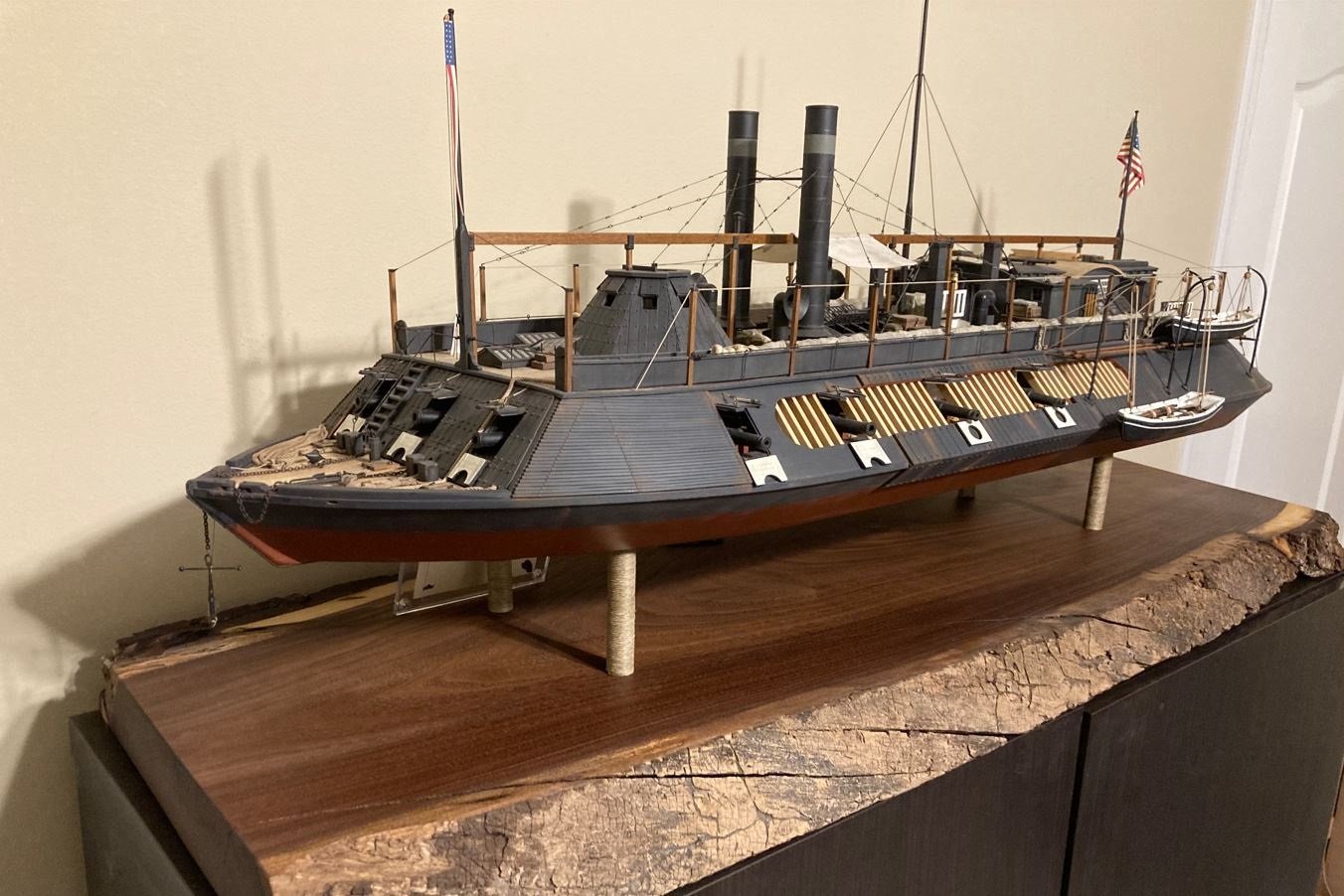
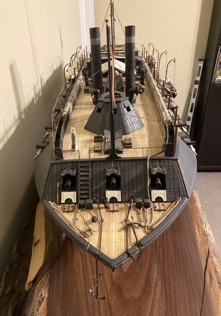
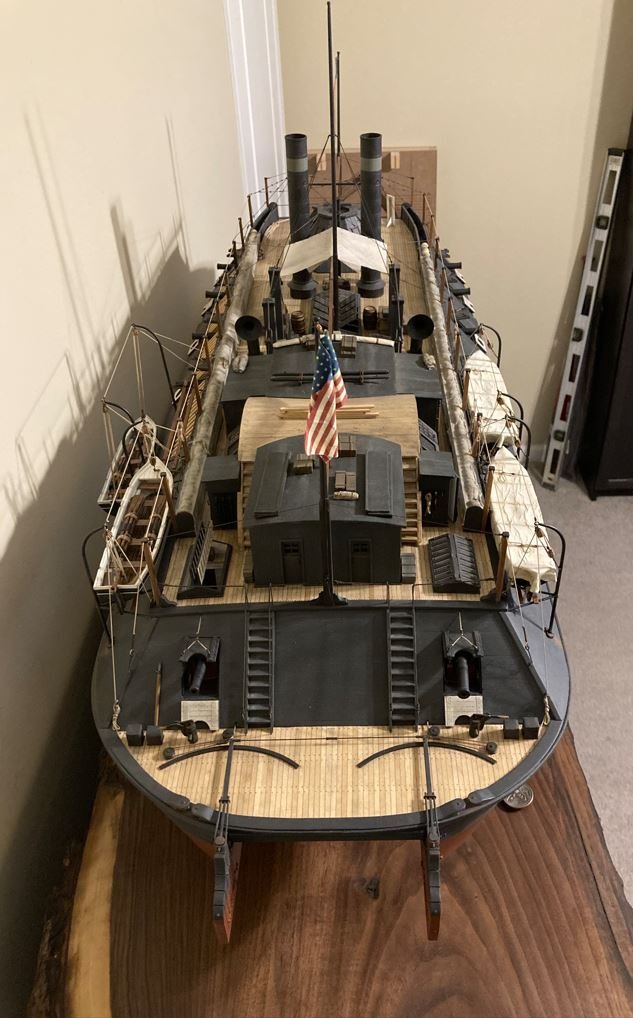
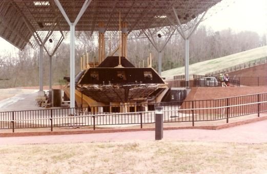
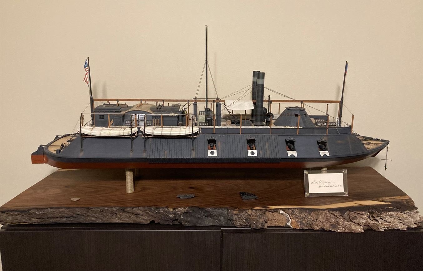
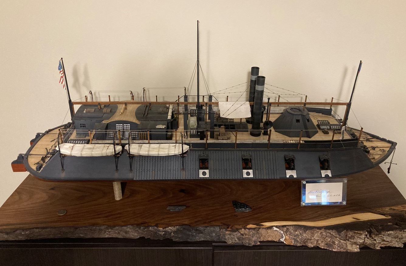
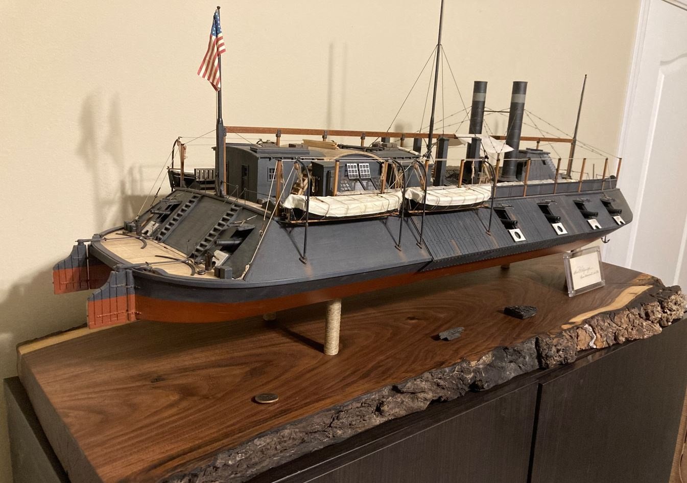
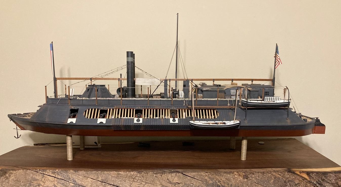
Hello again everyone, 160 years ago today, December 12, 1862, the USS Cairo had her rendezvous with destiny. While patrolling the Yazoo River about six miles north of Vicksburg Mississippi, Commander Thomas O. Selfridge and his crew of 175 men were on a torpedo (mine) clearing mission along with another City-Class iron clad the USS Pittsburgh, the Union Ram Queen of the West and two other tin clads, the Marmora & the Signal. Roughly four hours into the mission, two loud explosions in rapid succession, rocked the Cairo tearing a huge hole in her portside bow. As the forward hold started to fill with water, Commander Selfridge ordered his pilot to run the ship aground on the east bank of the river. Once the ship was on the bank he ordered part of the crew to secure a hawser to tree on the riverbank and the rest of the crew to abandon ship. 12 minutes after the explosions doomed the Cairo, she slipped her hawser and slid into her muddy resting place for the next 100 years. Not a single life was lost. In 1956 Edwin Bearss and two associates, Warren Grabau and Don Jacks, discovered the wreck and set out on a mission of their own to pull the Cairo from the muddy riverbed. On December 12, 1964, 102 years to the day of her sinking, the final piece of the sunken Ironclad was set on top of the recovery barge. The wreckage was then towed to Ingalls Shipyard in Pascagoula Mississippi where the pieces were to be reassembled, tagged and catalogued. Finally in 1977, after several years of neglect, red tape and debate, funding was secured and what remained of the Cairo was transported to Vicksburg National Military Park where she, along with the thousands of artifacts recovered with her, could permanently be displayed properly. In November of 1980 the Cairo reassembly was completed, the protective shelter built and the museum was opened to the public. I first saw the Cairo in the fall of 1984 when I was a Boy Scout. Our troop had taken a trip Vicksburg to hike the park tour road as part of some of our merit badge requirements. A few months prior to our visit, I had just finished my first ship model, Revell’s 1:96 scale USS Constitution. This was the model that started my life long love of model shipbuilding. I still recall as we came down the hill to the Cairo museum and I fist laid eyes on the display, I said to myself that one day I am going to build that ship. A photograph from my first visit to the Cairo in 1984. Well time passed and life went on, but that thought still remained in the back of my mind that one day I would get around to building my model of the Cairo. In 2011, I moved away from plastic models and started my first wooden ship model, ironically enough it was the USS Constitution cross section. Since that time I have been hooked and have not looked back. In 2014, on our way back from Parris Island, SC to see my daughter graduate from Marine Corps Boot Camp, the Admiral and I decided to take a side trip to Vicksburg NMP. It was then that my interest in the USS Cairo was renewed and I was finally determined that the build was going to happen one way or another. So I searched and searched, but could not find a model kit of the Cairo that I personally felt was good enough (or big enough) to feed my desire to fulfill my dream. So I decided that it was going to have to be a scratch build. Well with only three years of wooden ship building under my belt, I felt that my skills were just not there yet, so I set out to hone my skills by completing more model kits until I felt the time was right. During my Chaperon build, I did a lot of additional research and I added a lot of extra scratch-built details that I had found from contemporary photos of her and from a lot of help from people here on MSW. So in 2020, after completing my Chaperon kit I felt that I had enough practice under my belt that it was time to knuckle down and start a full scratch build. In my mind there was no debating that the Cairo was going to be that build. So here it is, after 38 years of dreaming and over 2 ½ years of work, my final product of the USS Cairo City-Class Ironclad circa 1862. I want to thank all of those who have stopped by to have a look and those who have stuck with me through this build, offering up your suggestions, comments and words of encouragement. It means so much to me to have you following along. I’ll have better pictures coming soon for the Gallery. My daughter works with a professional photographer that is going to do a shoot for me. She is a bit tied up through the holidays, but hopefully after the new year I should have some good ones to add. I am going to take a short break through the holidays, I need to have a procedure done that will put me out of commission for a few weeks, but I need to get it done this year so insurance will pay for it. After that, I will be back at it. I’ve got another scratch build planned that is a bit outside of my wheelhouse, but it should be fun. Thank you all! -Brian
- 739 replies
-
- 30
-

-

-

-
John, those bends are a bit precarious, especially along the scribed lines. Compound that with the instructions having you increase the scribed depth, and you are just asking for the piece to break. In my case, I did break my pieces and had to resort to gluing some card stock to the backside to help hold the bend. Thankfully the battens helped hide the breakage on the outside. Thanks for the tutorial on the proper way to bend this area. If I had used something solid instead of the provided jig, my results would have been so much better. -Brian
- 157 replies
-
- 2
-
-
- chaperon
- Model Shipways
- (and 1 more)
-
John, your build just keeps getting better with each post. Different approach to coloring your ropes, not only does it allow you have the color you want, but I would think that the paint would help stiffen the rope as well giving it a nice taught look. -Brian
- 238 replies
-
- 2
-
-
- Robert E Lee
- steamboat
- (and 3 more)
-
Thank you Keith, I am glad you saw that to. That is exactly the look I was going for. The grain of the wood matches the shape of the bow almost perfectly. 😁 -Brian
-
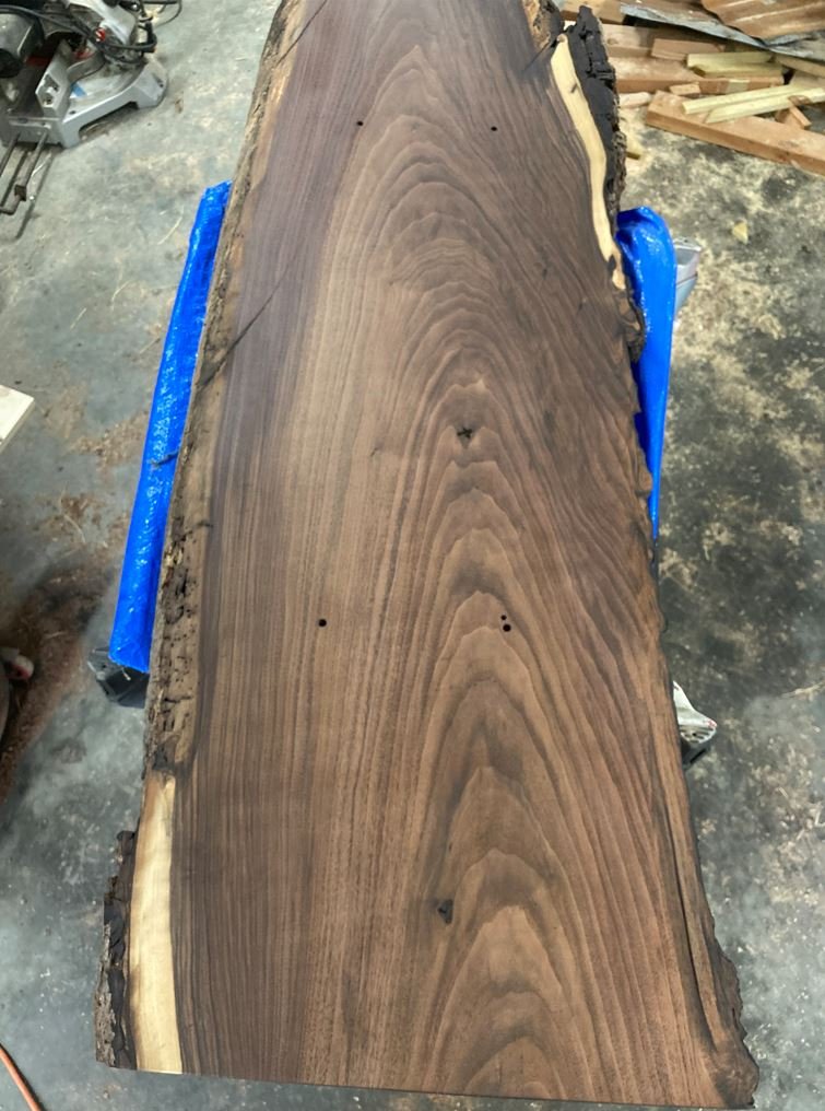
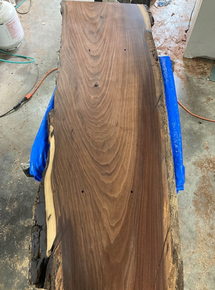
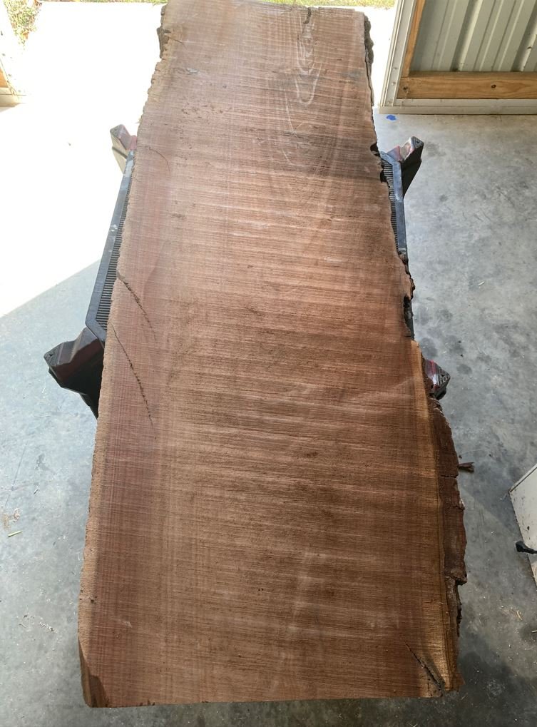
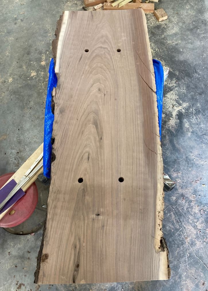
Hello everyone, It's getting down to the final details of my build, I am almost done. I just wanted to share this one update right quick on a little gem that I found this weekend. I was trying to decide how to display model properly. My plan was to build another case and mount it in there, eventually. Then the Admiral came up with the brilliant idea to mount it to a slab of wood. I tell you, I'm not sure what I would do without her. So I looked around on the interweb for some ideas and then it came to me, a live edge black walnut slab. So headed down to the sawmill and picked up this beautiful piece of wood. It is a tad bit thicker that what I was wanting (about 2" thick), but I think it will work out perfectly. So I took it out to the barn and gave it a good sanding to get the sawmill chatter marks out of it. Started off with an 80 grit and worked my way up to 400 grit and then a final rub down with some #000 steel wool. Once sanded and dusted, I then applied one coat of Tung Oil to it and let it dry. and then a second. Just finished with this coat and I think that should do it. There are some pretty porous areas on the edges that will need a few extra coats to soak in, but the main part looks perfect. Once this coat cures I am going to flip in over and work on getting the base ready for the light switch and battery compartment. Can't wait to see what the boat looks like mounted to this beauty. Oh, did I mention this son of a gun weighs about 40 lbs. (without the boat). I'm going to have to find a heavy duty shelf to put this on. -Brian
- 739 replies
-
- 18
-
-
-
As usual Keith beautiful work. I generally use a small soldering iron and run it up and down the sides of the heat shrink tubing, not touching it, but close enough to get it to shrink. I use this method in the more delicate areas, or where the surrounding area can be affected by the heat gun. -Brian
-
I have a set of diamond needle files that work great for fine sanding wood in those hard to reach places, but have never used one on a saw. Seems that the speed factor would tend to gall up the blade pretty quick with the wood fibers. -Brian.
-
Roger, I had looked at those several years ago, but they were way too expensive. They are also proud of their saws as well, and having to replace the cartridge every time it was used can get a little pricy. What a steal! I bought my Craftsman about 20 years ago and paid about $1500 for it, and that was the floor model. Not to mention it didn't come with a trailer. Had to haul it home in the truck and have three friends help unload it. 😁 -Brian
-
Eric I’m starting to get the feeling that the instructions for this model are not very useful. This may be a build as you go and use the instructions just for parts placement. The side casement armor does indeed sit under the hurricane deck trim/water ways. It overlaps the armor plating, I would guess to keep most of the runoff from going between the plates and the casements. I noticed that the forward railroad irons do the same thing that I had an issue in with my build where the top few rows tapered up into the hurricane deck trim. Later on in my build I found the reason for this was that the angles between the forward casements and the side casements were different. The HSR plans have both casements at a 45 degree angle but later research shows the forwards were 35 degrees. I love the toddler tenacity of wanting to work on your model right now! 😁 -Brian
- 113 replies
-
- 5
-
-
- Cairo
- BlueJacket Shipcrafters
- (and 1 more)
-
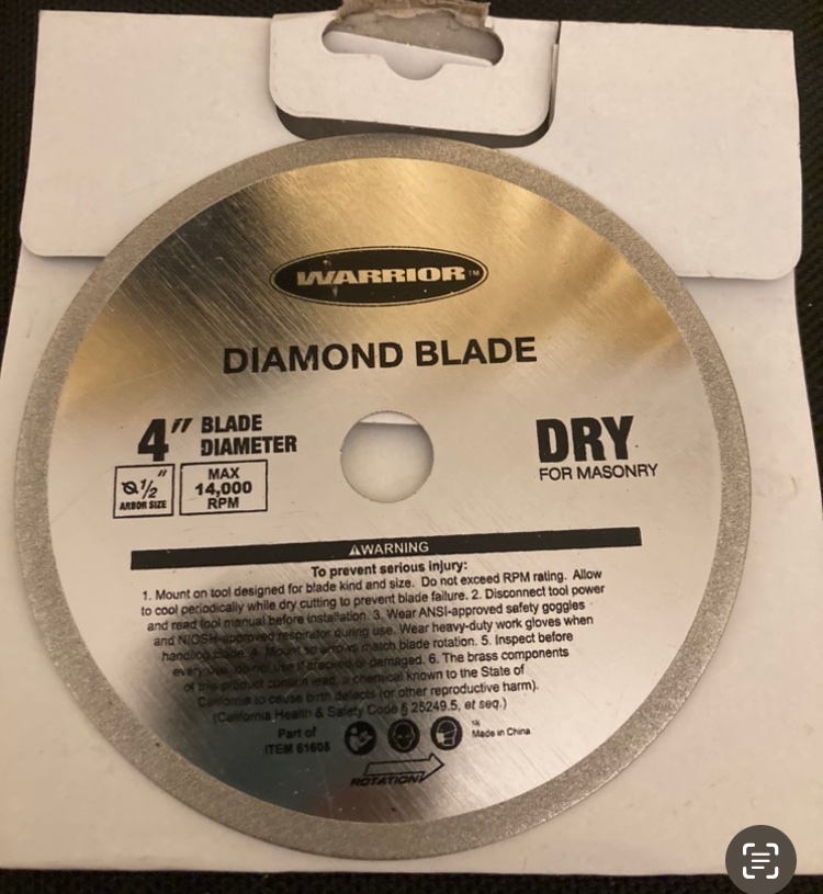
I can’t speak for the UK Keith but over here we have a place called Harbor Freight. They sell tools really cheap, but of course they are cheap. Several years ago when I first got into wooden ship building I purchase one of their cheap mini table saws for something like $20. Needless to say, you get what you pay for, and it wouldn’t cut a clean line for anything. Long story short, it came with a diamond blade, but it does say for masonry. Never thought to try it on wood. Good to know that digit reattachment is easier with the Byrnes. Good selling point. I sure hope this information doesn’t come from personal experience though. 😁 -Brian
-
Camel by RGL - FINISHED - Machinen Krieger - 1/20
mbp521 replied to RGL's topic in Non-ship/categorised builds
Beautiful work Greg! Definitely an interesting subject, but it looks great. -Brian -
Hi Kurt, unfortunately I do not have a zero clearance insert for my saw. I had never really thought that I would use the saw for small detail work like ship modelling. However, that is something that I will look into if I can't swing the Byrnes for a while. I'll definitely bring the finger saving idea up to the wife though. If no one hears anything from me for a while I may be recovering from a mysterious frying pan upside the head accident. 😁 -Brian
-
Alex-Ks1, thank you for stopping by. I have been eye-balling a Byrnes precision table saw for some time now, it just hasn't been in the budget as of yet. I cut the bulkheads on my Craftsman 10" Industrial table saw from 1/4" plywood, with a brand new carbide tipped blade. Even with a new blade I just couldn't keep the plywood from shredding. Of course the plywood was not of the best quality either, but this is the reason for all the tear-outs. Fortunately all the bulkheads were hidden and none of the "nastiness" of the plywood can be seen. For the finer stuff, I used an Xacto saw blade and a lot of sandpaper. One of these days I may be able to talk the Admiral into a Byrnes (fingers crossed). -Brian
-
Glad to see another update. I’m not a huge fan of ME paints. They do have some nice colors that are, for the most part, true to some of the originals, but I find them a bit thick and in need of thinning before applying. I love the Vallejo paints. They have so many more color options available and they apply nicely right out of the bottle. Fantastic job on getting the hull shaped, and I love the plan you have to weather the deck. I’m a big fan of natural wood decks. I wouldn’t sweat the PE too much. I found that it was easier to work with than I first thought as well. Well, at least the bigger parts are. Haven’t had the joy of working with the tiny stuff yet. 😁 -Brian
- 113 replies
-
- 4
-
-
- Cairo
- BlueJacket Shipcrafters
- (and 1 more)
-
Thank you John for the kind words. I see that you are new to MSW and I hope you are planning to do a build log on your model. There are so many wonderful resources here at MSW and I would love to follow along and help out where I can. - Brian
-
Looks like you handled the pressure pretty well. Nice work on the pilot house. -Brian
- 238 replies
-
- 2
-
-
-
- Robert E Lee
- steamboat
- (and 3 more)
-
Timber-framed outdoor kitchen - Cathead - 1:1 scale
mbp521 replied to Cathead's topic in Non-ship/categorised builds
Nice quarry Eric. Looks like the freezer is beginning to get stocked. -Brian -
Looking beautiful Tom. I use the CA on the thread method all the time. It certainly helps when threading the smaller ropes through the blocks. -Brian

