HOLIDAY DONATION DRIVE - SUPPORT MSW - DO YOUR PART TO KEEP THIS GREAT FORUM GOING! (Only 13 donations so far - C'mon guys!)
×


mbp521
-
Posts
1,002 -
Joined
-
Last visited
Content Type
Profiles
Forums
Gallery
Events
Everything posted by mbp521
-
 Keith, I second Glen’s comment above. I feel as if I am getting the proverbial leg pull that this is your first attempt at a ship build. What amazing work for a first-timer! -Brian
 -
Eberhard, I can sympathize with you on this one. All the work that goes into the fine details that will eventually get covered up is a bit heartbreaking. Thank goodness we have the build log pictures to fall back on to see the wonderful work you have done. -Brian
-
Guilty, on every wooden model I have ever built. Something about the lure of creating sawdust and seeing the uneven planks laying there tempts me to get them sanded immediately. I just can’t help myself. I’m going to have to look into those clamps. I like the pointed ends on them. -Brian
- 157 replies
-
- 1
-

-
- chaperon
- Model Shipways
- (and 1 more)
-
Amazing work as always Keith! The pictures were well worth the wait and the tease. 😀 Still looking for the clutter though. -Brian
-
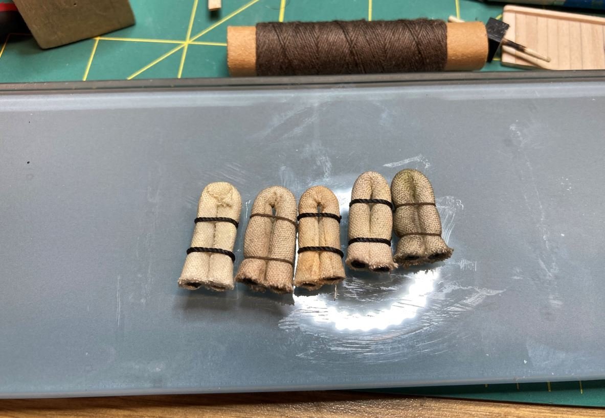
Keith, To be honest, each one of these little projects were done in one sitting, with the exception of the davit sockets which I had to wait on the Milliput to harden and the hammocks. So over the past month+ since my last update, this adds up to about maybe seven days at the workbench. Not as much time as I like to spend. As for the fireman's hammock, I think I did get carried away with the weathering a tad bit on that one. This picture is of my first few attempts and I did get a little heavy handed with the weathering powder. I'm sure that some of the sailors carried their gear with them from ship to ship, so this hammock may have belonged to an old sea dog whos seen a lot of action over his years. Sounds like a good story anyway. I really appreciate the comment on this being one of your favorite MSW builds. Given the quality of some of the other builds I've seen on here, that truly means a lot my friend. -Brian
-
LJP, Just ran across your build, and what a beautiful job you have done so far! Fantastic detail on the engines and boilers. I'm going to pull up a chair and follow along. -Brian
-
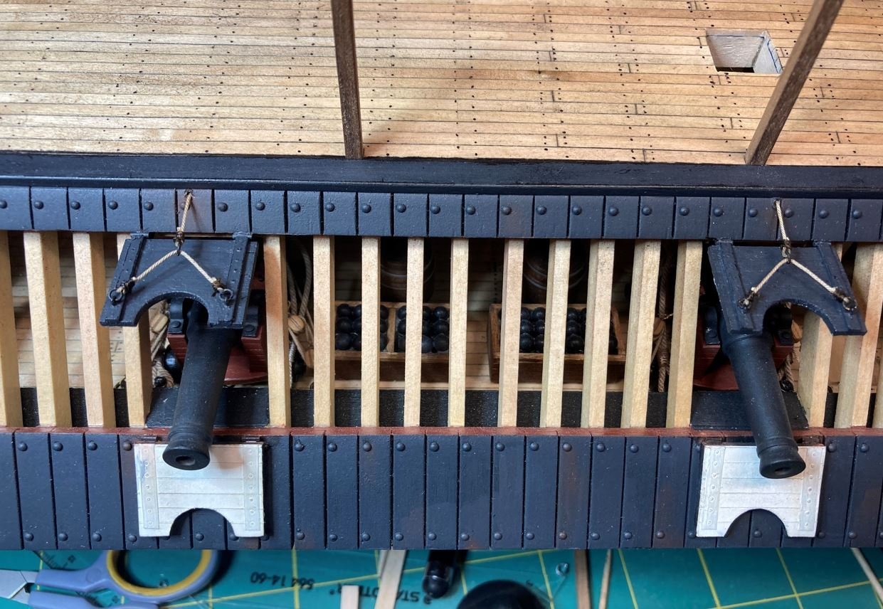
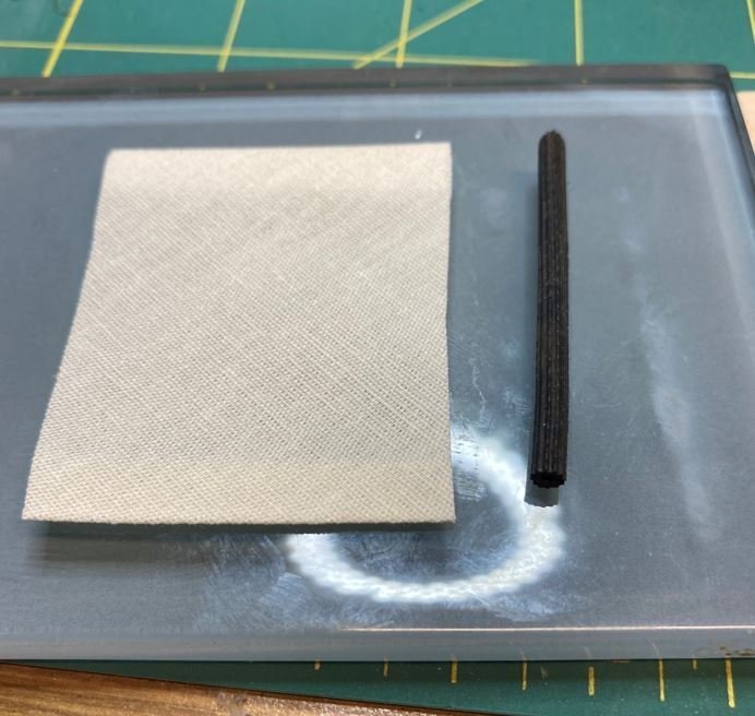
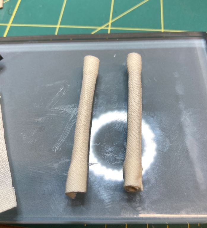
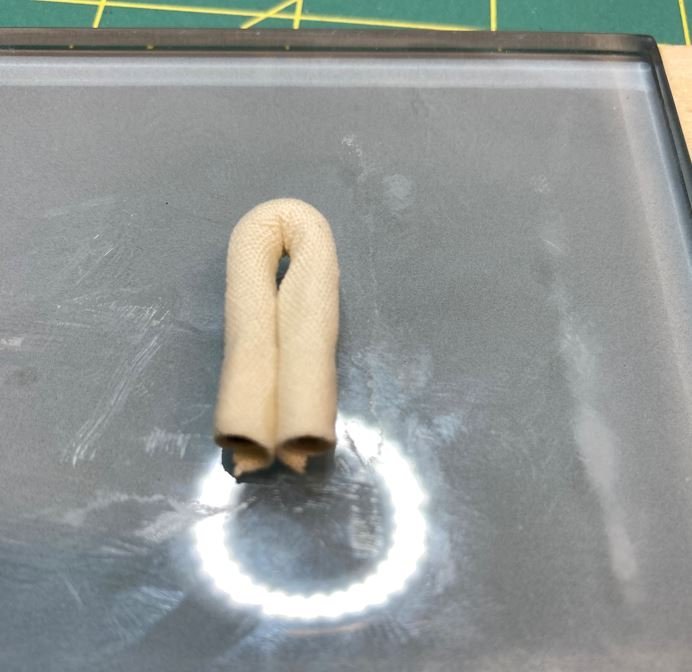
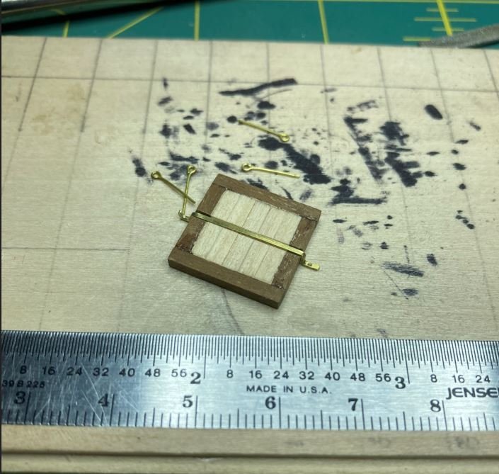
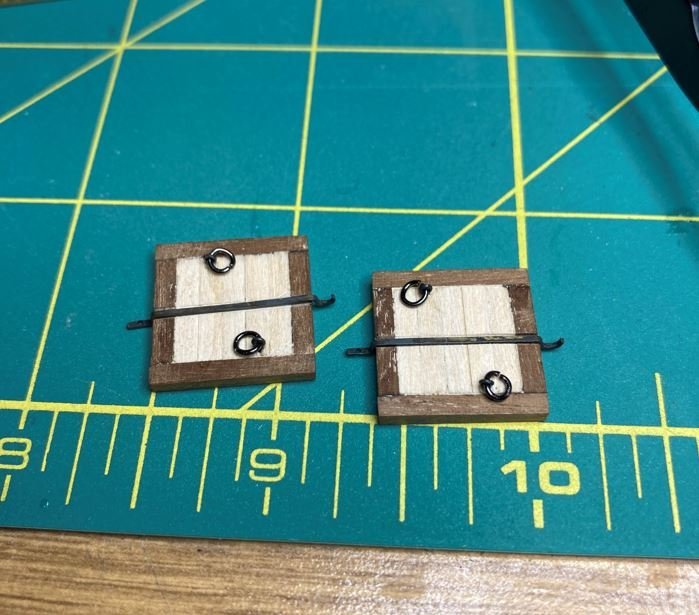
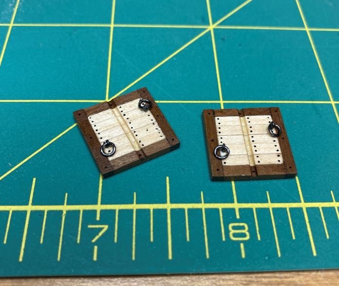
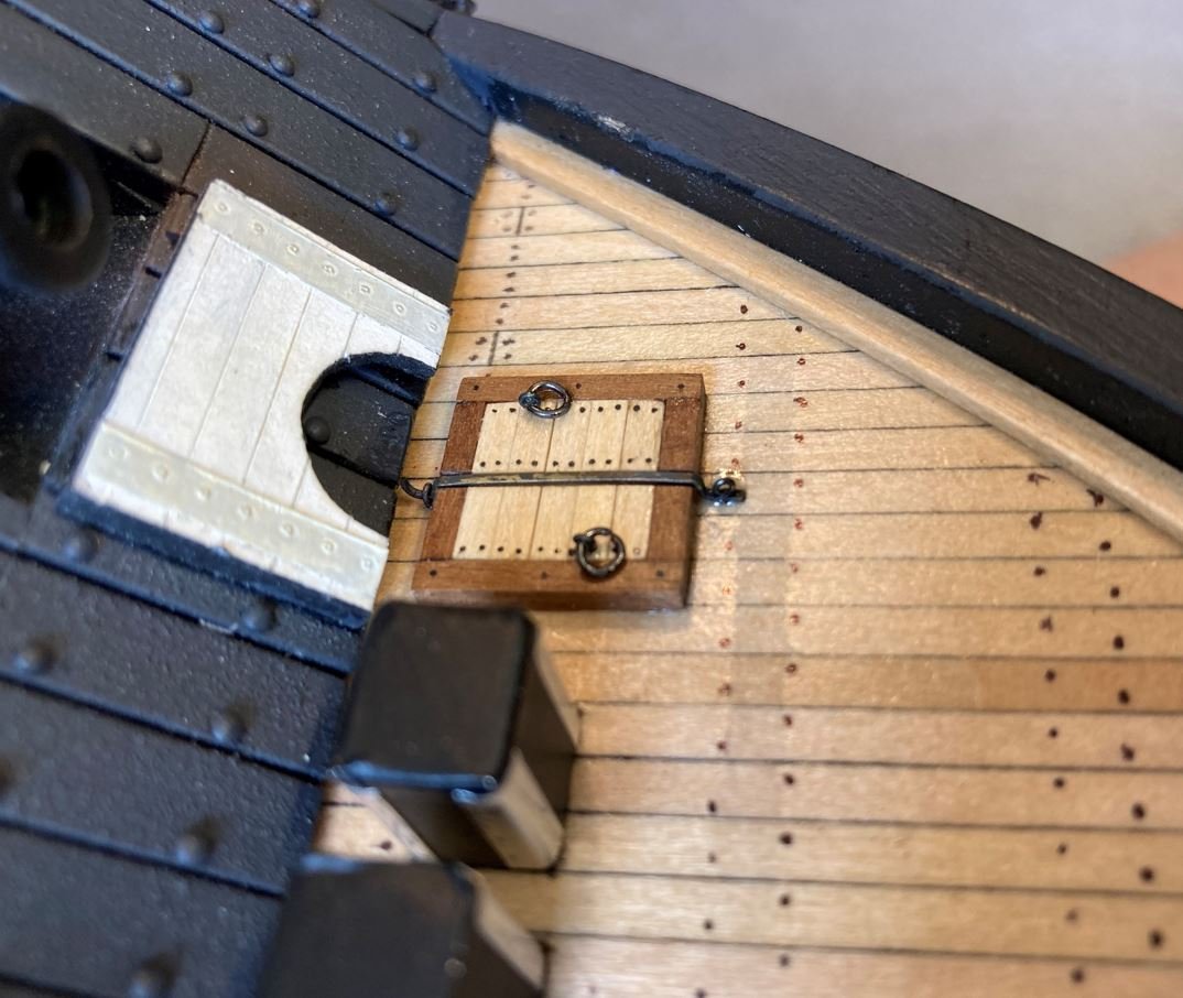
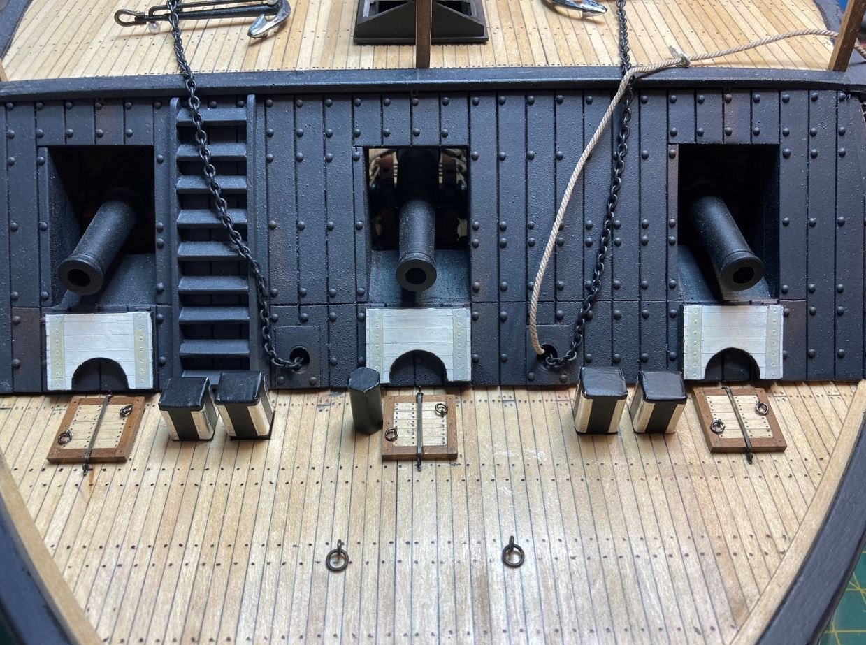
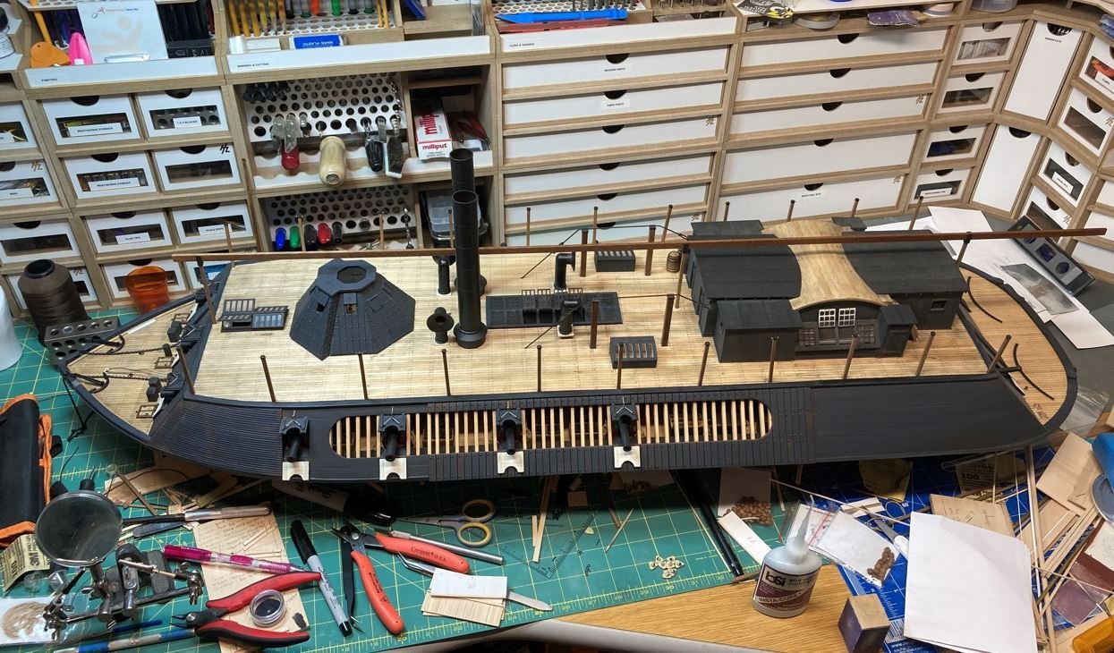
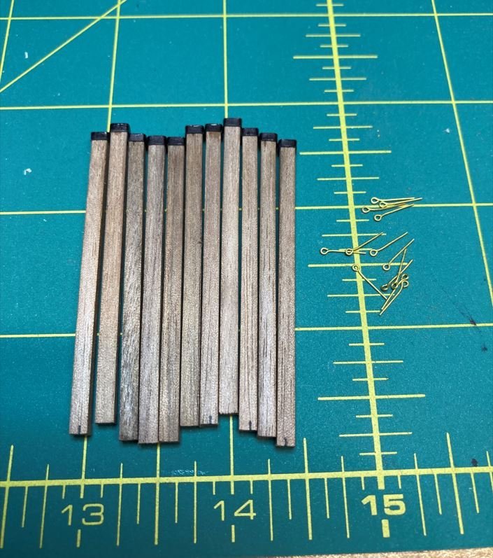
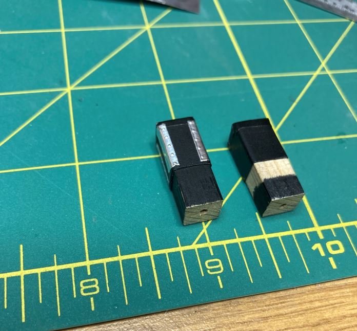
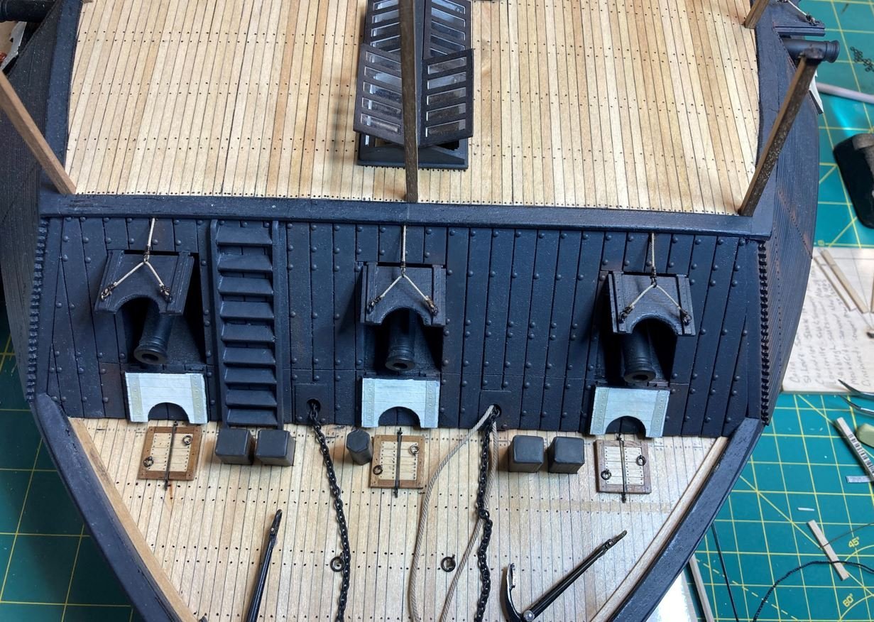
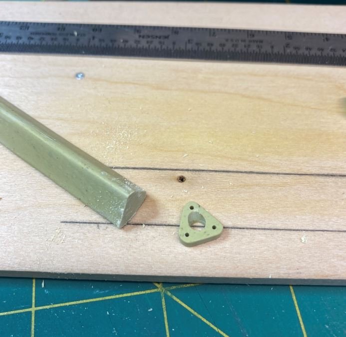
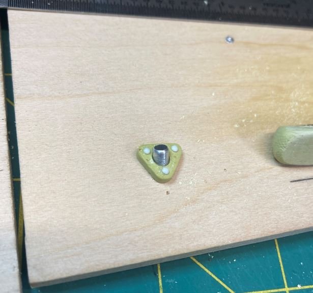
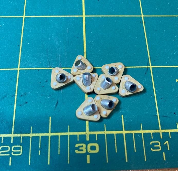
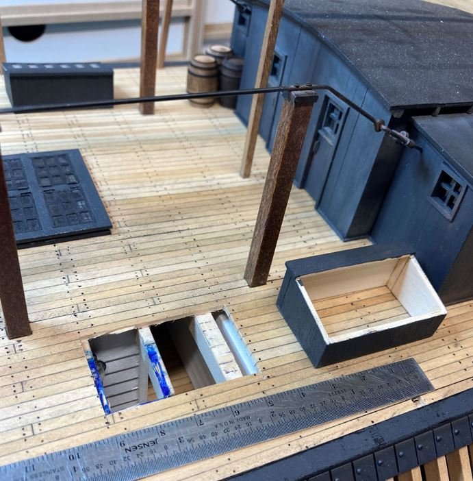
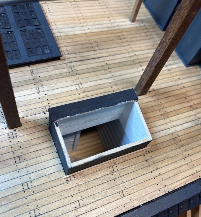
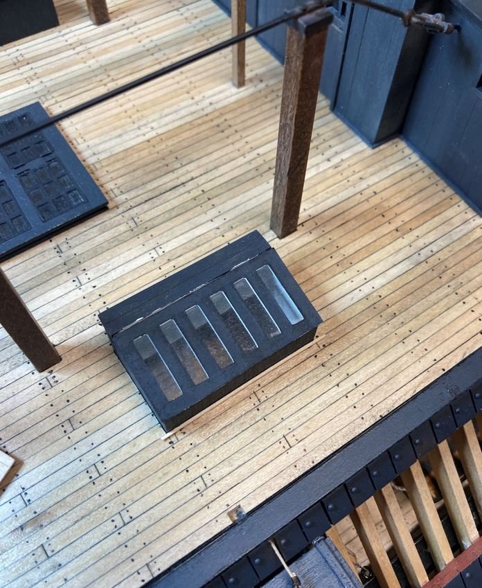
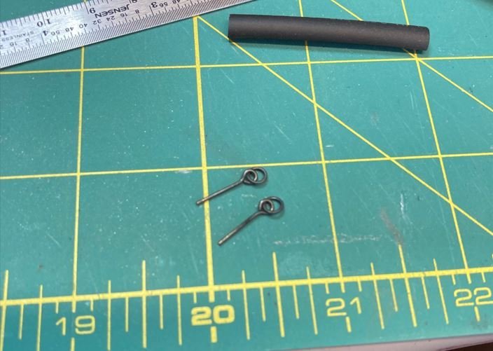
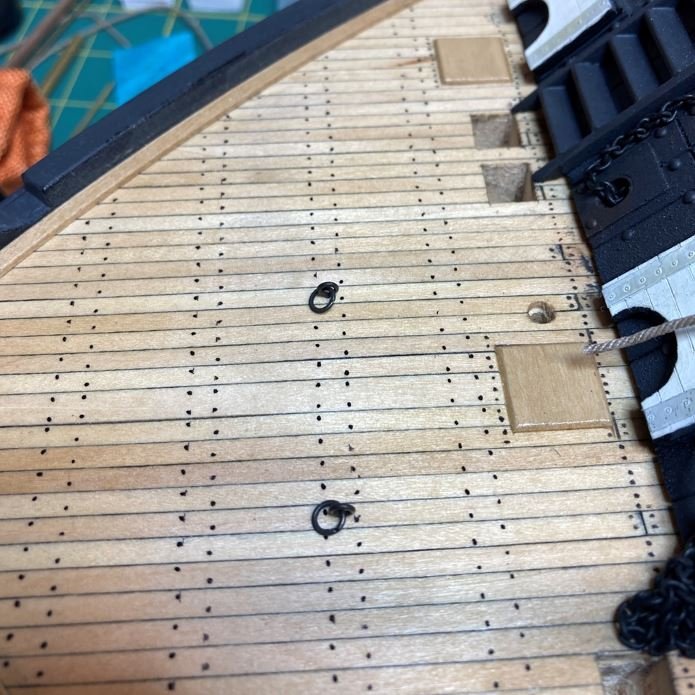
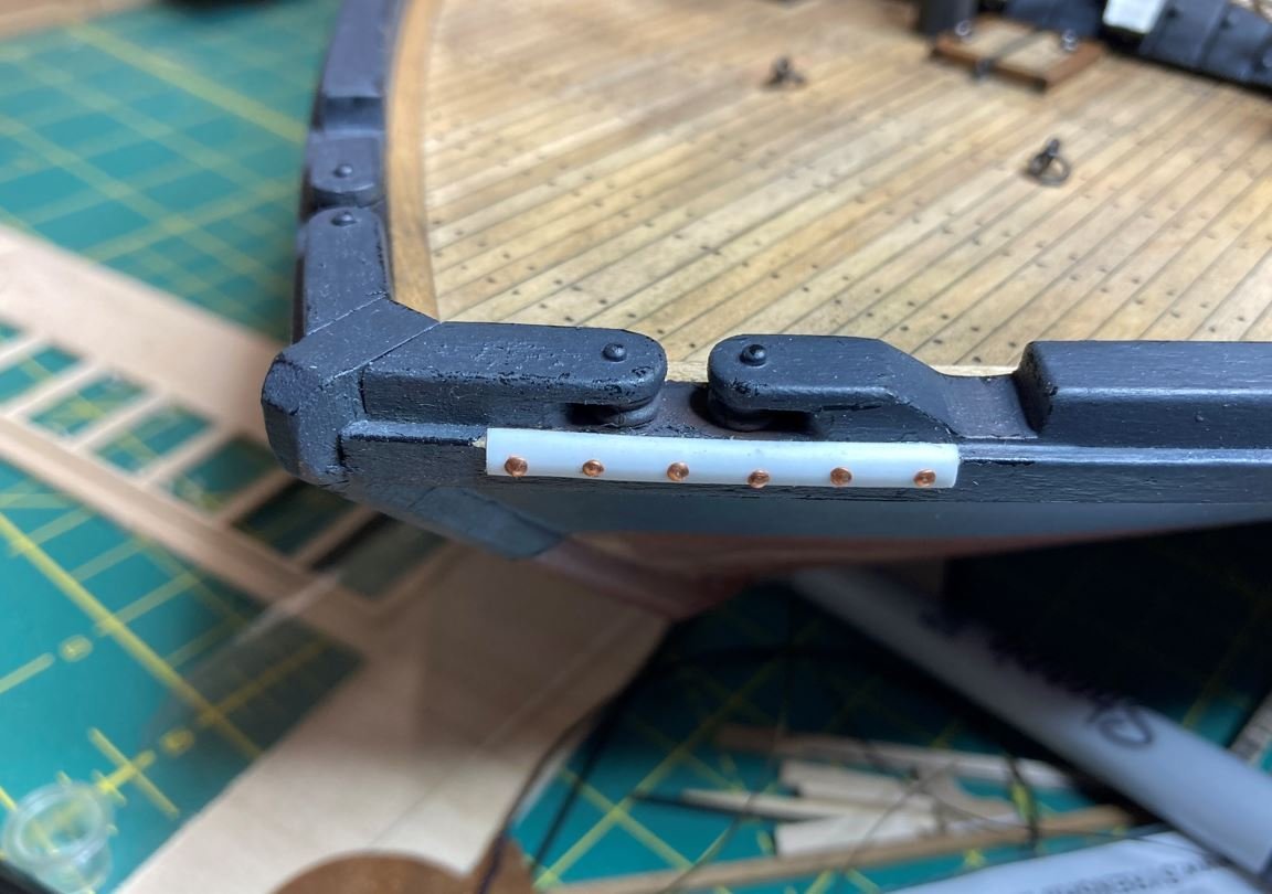
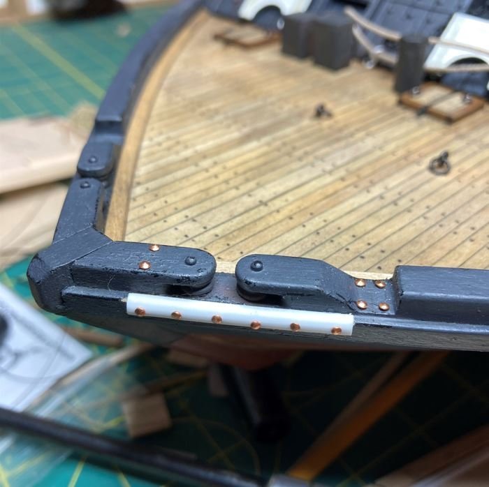
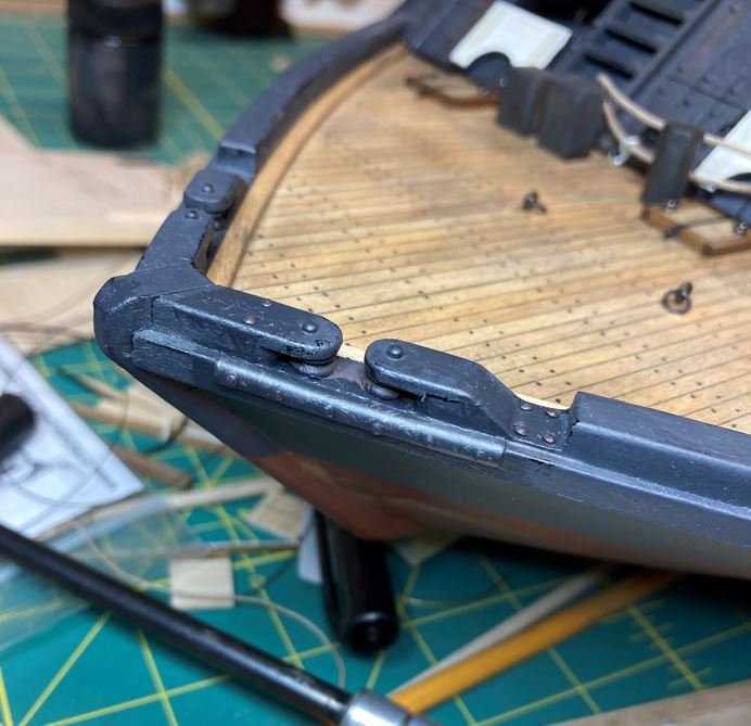
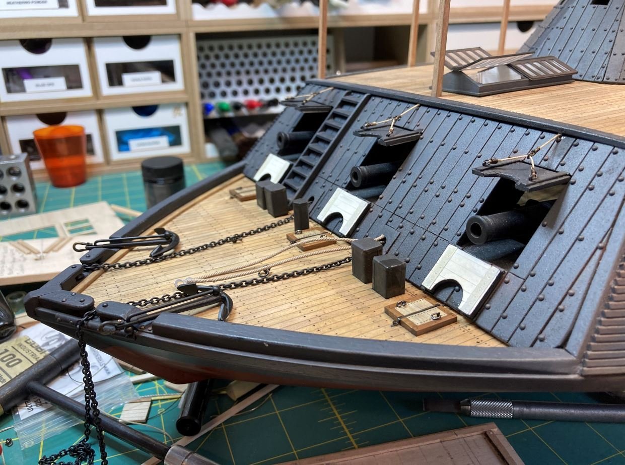
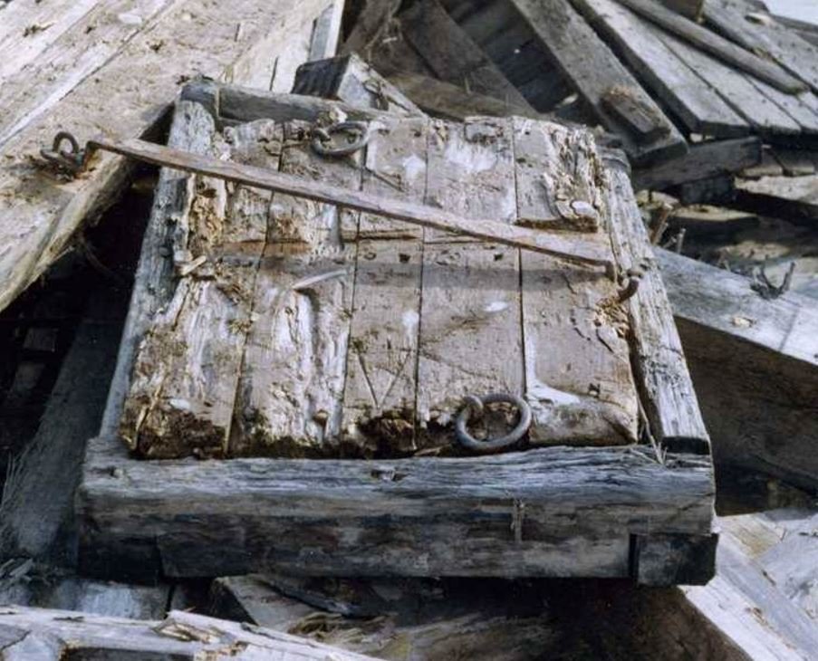
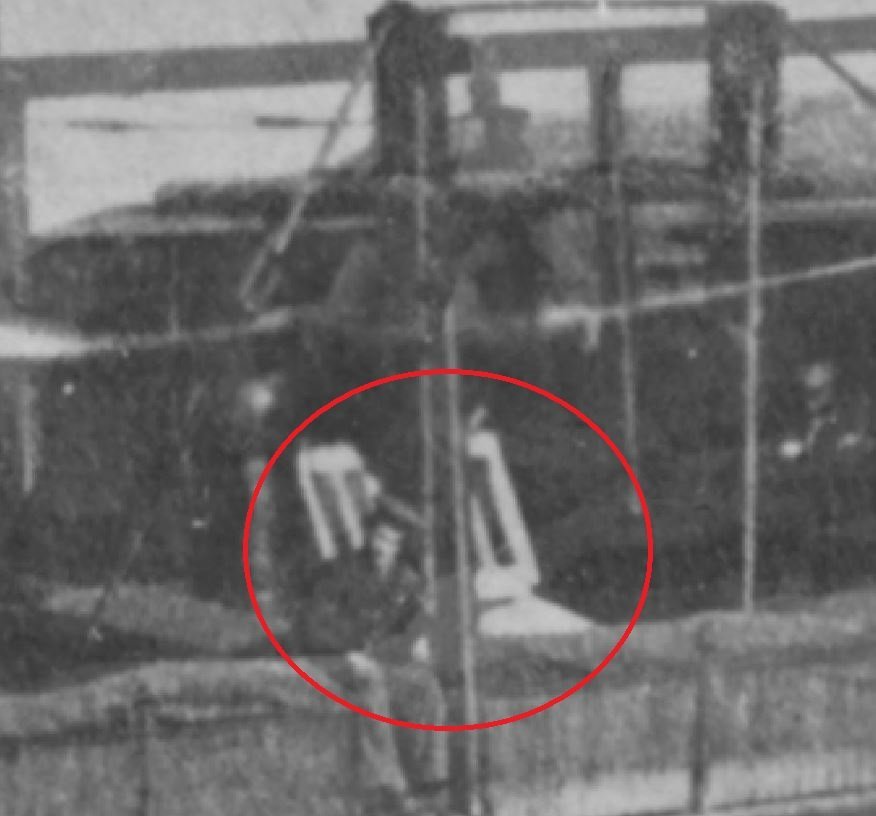
Hello again Everyone, I'm back with a short update. Not a whole lot has been done lately, Unfortunately I have been spending a lot of build time on research and not much building, but I want to make sure that I get things right. Most of the work as of lately has been small projects. I started off with making some of the hammocks. My plan is to cover most of the hammock racks with a tarp, but leave a few exposed for details and some of the racks empty to show other details. I started by using a small square of sail cloth and some rubber screen spline, I glued one side of the cloth to the spline and rolled it up to cover the entire spline. Next, the assembly was folded in half and glued together. Finally, I tied the sides together and added a little weathering to give each one a unique look. This was the first batch. I made up about 40 of these and I will get them installed in the hammock racks, once I get them built. Up next was the stationaries (best guess at what these were called, since they were pretty unique to these vessels). These were were used as attachment points for the hammock racks, chimney support cables, canopies and numerous other purposes. They were pretty straight forward to build, I just used 3mm square mahogany stock cut to length. I added strips of heat shrink to simulate the caps and small eyebolts to the tops for anchor points of the various attachments. During my research and many hours of staring at old (and new) photographs, I discovered that I missed part of the metal plating on the bollards. These look to be added to prevent wear of the timbers from the shoring ropes. I just simulated these with some aluminum tape and wrapped them around the corners. Another redo on the build were the deck hatches on the forward deck. I ran across a photo from the salvage of the Cairo that showed great detail of the hatches. Unfortunately, most of these were located on the gun deck, inside the casements and it was too late to go back in a fix my error. However, there were three hatches located on the forward deck, just in front of each cannon. I can find no other information on what happened to the hatch in the picture below. From what I can recall, it is not on the boat itself and I do not remember if it is in the museum or not. However, the picture gives good detail of what they looked like so I rebuilt the three that I had access to. Original hatch from the recovery. New hatch in place along with the redone bollards. Another small install were the eyebolts placed on the deck. Overall view of the forward deck with the bollards, hatches and eyebolts. I was having a difficult time trying to figure out how to build the base sockets for the davits. I had initially tried making these from wood, but I couldn't seem to get a consistent size on them. I finally tried making a triangle out of Milliput and cutting the pieces from that. I drilled out the center for the anchor point as well as the three bolt holes that secure them to the casements. I then put a piece of aluminum tubing for the anchor point and then simulated the rivets with small styrene, in the same way that I did the rivets for the armor plating. One down, seven more to go. All eight completed. I finished up the fairleads that I started a while back. I had intended to do this back when I initially built them, but it was one of those things that I forgot about until I was looking at the pictures, and realized, oh yeah, I need to do that. To get the rounded effect, I took some 1/8" styrene tubing, split it in half, and contoured the deck to fit in position. I added some small nails for the bolt points and glued everything into position. More nails were added to show other mounting points. Then the gaps filled in and everything painted up. A little touchup paint and some weathering. I also went ahead and added the port side upper cannon doors and rigged them up. Finally, one area of research that has taken up most of time lately was trying to figure out if there was a hatchway from the Hurricane Deck to the Gun Deck below, located between the hog chain supports. To me this definitely looks to be some sort of access and my justification it is that it looks to be constructed similarly and painted in the same scheme as the forward skylight, the long narrow windows, black exterior and white interior. What else could it be? Another deciding factor was the location of the hatchway. If it was indeed located where it is shown, it would place the inboard side of the hatchway wall directly in line with the exterior wall of the boiler room. They could have placed a ladder on the outside boiler room wall with easy access to the hatchway above and not be in the way of foot traffic on the gun deck. Well after I searched and searched for any information on this and coming up empty, I made the decision to go ahead and build it up as described. Previously, I had built these up on the off chance that I could find information on them, and since I went through the effort of building them, I was going to go ahead and use them. With that being said, I put my model on a table in the middle of the room to try and get the same view angle of the model as the photograph that was taken of the Cairo way back when. I did this to try and get the proper location of the hatchway in relation to the supports as well as get the proper location of the funnels. The HSR plans show the funnels located just outboard of the hog chain supports and directly between them. This is definitely an error on the plans. From the snip below I have circled the hatchway in red, and just forward of that you can see the portside funnel, and it shows it to be forward of the forward hog chain support. When I aligned my view angle up on my model with the photograph, this position was correct. So armed with this information, I am placing the hatchway between the hog chain supports and moving the funnel forward of the supports and slightly outboard so that there is clearance enough for the funnel to rotate a full 360 degrees with out encountering any obstacles. This is my decision and I am sticking with it. Location of the hatchway to the Gun Deck. Hatchway in place. Note how the walls line up and provide a perfect place to mount a ladder inside. I am happy with my decision, and di believe that I am on the right path with this one. That is all for this update, hopefully I can make better progress for next time now that my hatchway obstacle is out of the way. I am going to continue to work on the starboard hatch and build up the ladders and get them in place. Then, hopefully I can get started on building the hammock nets. Thank you all for stopping by and liking my work, and I look forward to any additional comments you might have about my decision on the hatchways. -Brian Oh yeah, and the overall view as she sits today.

- 739 replies
-
- 20
-

-
-

-
George, I've used their replacement line on a couple of occasions and I have to say that it is quick and painless. I have dealt with Ed each time and he is very good at getting the parts out to you, for the most part, within a week. Nothing but good things to say about it. Thanks for sharing the pictures of your trip, Looks like a good time. Looking forward to your updates. -Brian
-
Tim, Stunning work by the entire group. I am so glad that you are posting these. Thank you! -Brian
-
John, no laughing here. I do the same thing with a similar setup. Sure helps keep things organized and easy to find. Hope your jig is able to get the tilt out of your stern. Funny how the slightest things out of kilter can just nag at you until you finally give in and fix them. -Brian
- 157 replies
-
- 4
-
-
- chaperon
- Model Shipways
- (and 1 more)
-
Tim, I’m loving these updates! What a wonderful job you guys did on the canons. You would never know they were wood from the way they were painted. -Brian
-
USS Merrimack 1855 by threebs
mbp521 replied to threebs's topic in - Build logs for subjects built 1851 - 1900
And away you go! Nice to see the build under way. Great start. -Brian -
George, she is coming along very nicely. I love the description of “practice side” as being the non-display side. I’ll have to keep that term in mind. 😀 -Brian
-
Absolutely beautiful work Eberhard! I love all the minute details that you are able to get in to such a small scale. It just amazes me. -Brian
-
John, you are rolling right along with this build. Beautiful job so far. -Brian
- 238 replies
-
- 1
-
-
- Robert E Lee
- steamboat
- (and 3 more)
-
Beautiful Keith! This is the point where I think ship models start coming together. To me, the rigging adds a certain beauty them. 😀 -Brian
-
John, For the most part, the deck boards are all that the rub rail will be glued to. Since you are planning to plank the decks, this will give you another 1/32" more, but still not that much in relation to the width of the rub rail planks. On the real boats, there would have been support beams spaced along the sides to give more attachment surface for the rub rails, and for more realism you can add these if you want to. I chose not to add them since this area was not that visible. With the deck boards and added planking, I didn't have any trouble getting the rub rails to stay in place, especially with a liberal amount of CA applied. This definitely is an issue with the laser machine either not being set up correctly, or possibly the wood board used for the deck thinned a bit toward the outside edge. Either way, it is easy to see the piece was not processed correctly. Ed at Model Expo is excellent at getting replacement pieces sent out quickly, so hopefully it wont hold you up too much. Glad to see that you were able to overcome your "mishap" on the keel. As you stated the repairs will never be seen. I can also neither confirm or deny the same thing happened to me during my build. 😁 But a word of caution, watch those deck extension that run along the sides of the paddle wheel. They can be a bit fragile, I may or may not have broken those a time or to as well. 😜 -Brian
- 157 replies
-
- 1
-
-
- chaperon
- Model Shipways
- (and 1 more)
-
John, Glad to see you are under way with your Chaperon build, and great start so far! I finished mine a couple of years ago and have to tell you, this is a fantastic kit. There are a few minor things that you may need to tweak or add as you go, but nothing that will prevent you from completing a beautiful build, and as a bonus, there are plenty of steamboat knowledgeable people here on MSW to help you out along the way should you get stuck on something. Really looking forward to following along on your journey. -Brian
- 157 replies
-
- 3
-
-
- chaperon
- Model Shipways
- (and 1 more)
-
Johnhoward, what great information! This definitely clears up the nonexistence of the hatches over the fire room. Thank you so much Pat. I’m still trying to dig up more information on the hatchways between the hog chain supports, but I am almost convinced that the aft ventilation funnels on Cairo were located inboard of the hog chain supports and not outboard like the plans show. I’ve even gone so far as to set up my camera at the similar angle as the original photograph and located the funnels where they are in the photograph in relation to the supports and chimneys and they definitely look to inboard. I’ve still got some playing around to do with this, but I should have some resolution soon. -Brian
-
No need to feel guilty Keith. Research all part of it, and I have had a blast researching mine. No matter how frustrating at times the research is, the conversations that are inspired by said research, are priceless. However, with that being said, I have already begun research on one of my next projects. Fortunately, there is a little more documented history on it so it won’t be near as hard to get things right. -Brian
-
Keith, I love the old photos! Thanks for posting them. They seem to bring life to the ships we build. What I wouldn’t give to have this type of collection on the Cairo. Sure would save a lot of guesswork in my build. It’s funny how the Navy can have an over abundance of photos of one ship an only a single one for another. I guess that ships like the Tennessee were more likely to dock at more populated areas where cameras were readily available, whereas the Brown Water Navy tied up to the riverbanks in more remote locations. Regardless, that is a great collection you have there. Thanks again for sharing. -Brian
-
Very nicely done John. Big fan of the lighting. I find that it just adds just the right amount of realism to the build along with highlighting some of the otherwise hidden details. -Brian
- 238 replies
-
- 2
-
-
-
- Robert E Lee
- steamboat
- (and 3 more)
-
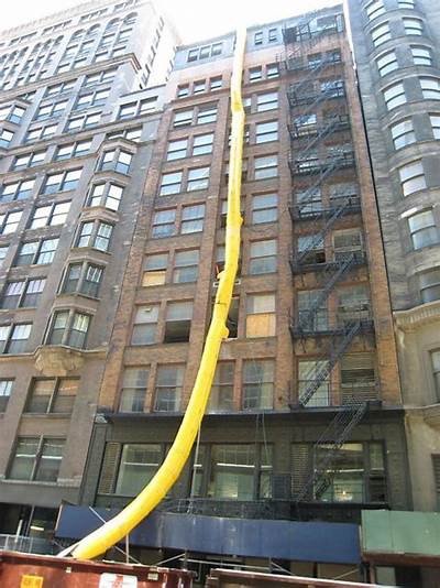
Here is another thought. To keep the ash from being blown around everywhere they employed an ash chute to dump the waste overboard. This could be similar to the trash chutes you sometimes see on multi-story buildings under construction. Maybe something like this. The chute would have been flexible, made of canvas or asbestos and could have been folded or rolled up for easy stowage. -Brian