HOLIDAY DONATION DRIVE - SUPPORT MSW - DO YOUR PART TO KEEP THIS GREAT FORUM GOING! (Only 13 donations so far - C'mon guys!)
×


mbp521
-
Posts
1,002 -
Joined
-
Last visited
Content Type
Profiles
Forums
Gallery
Events
Everything posted by mbp521
-
 I’m having trouble distinguishing between the model and the real launch. Amazing! -Brian
 -
Keith, My apologies for being way late to the party on this. I just spent the last couple of days going through all 63 pages of this magnificent build. Man have I been missing out! What a beautiful model you have going on here. You are definitely a master of your craft and I feel so insignificant now. I know I am jumping late, but I'm definitely on for the remainder of the journey. -Brian
-
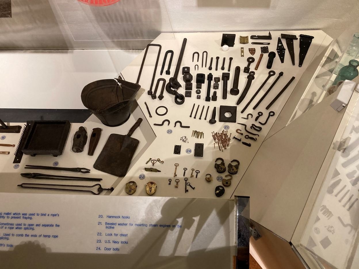
Slow is good. We are a patient group, and it just means you are taking your time on a quality build. Beautiful job so far! As for the bottom planks being lined up, a good sanding and a few coats of paint should cover it nicely. And if you are going to mount it directly to the base, they’ll never be seen. -Brian
- 157 replies
-
- 1
-

-
- chaperon
- Model Shipways
- (and 1 more)
-
John, Glad to see you back at it. Nice job so far on the hull planking. You are correct, you can never have enough clamps in this hobby. -Brian
-
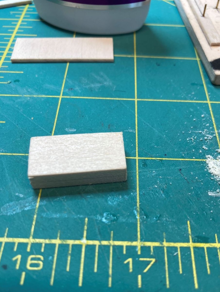
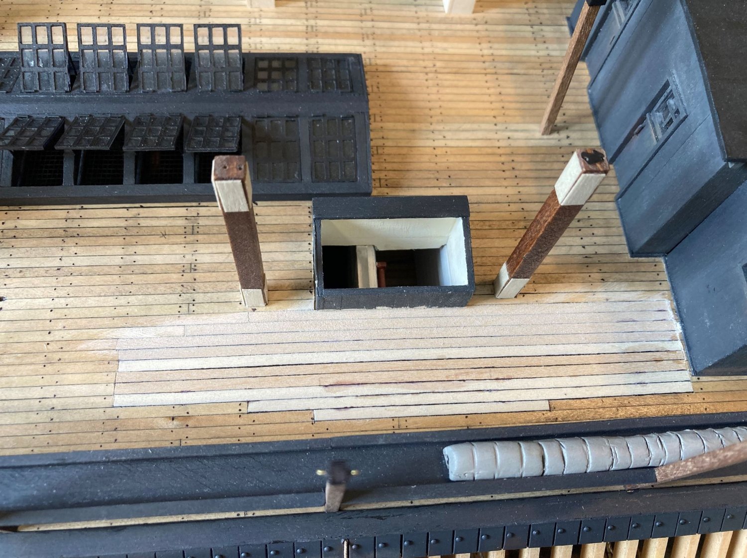
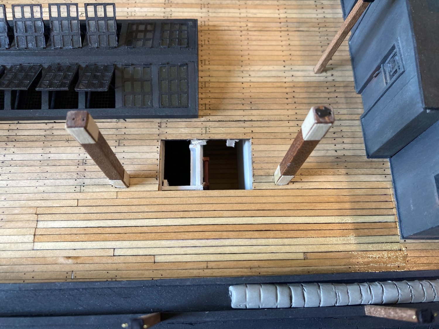
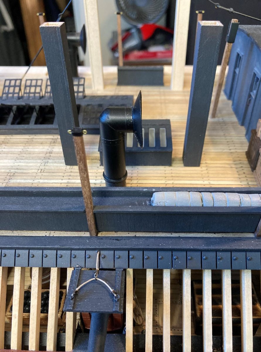
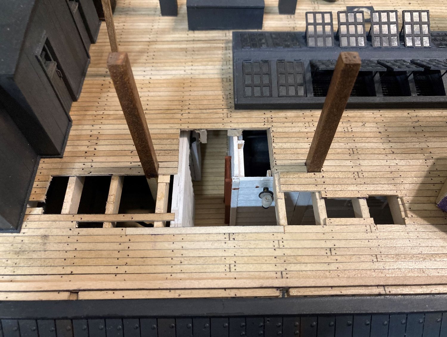
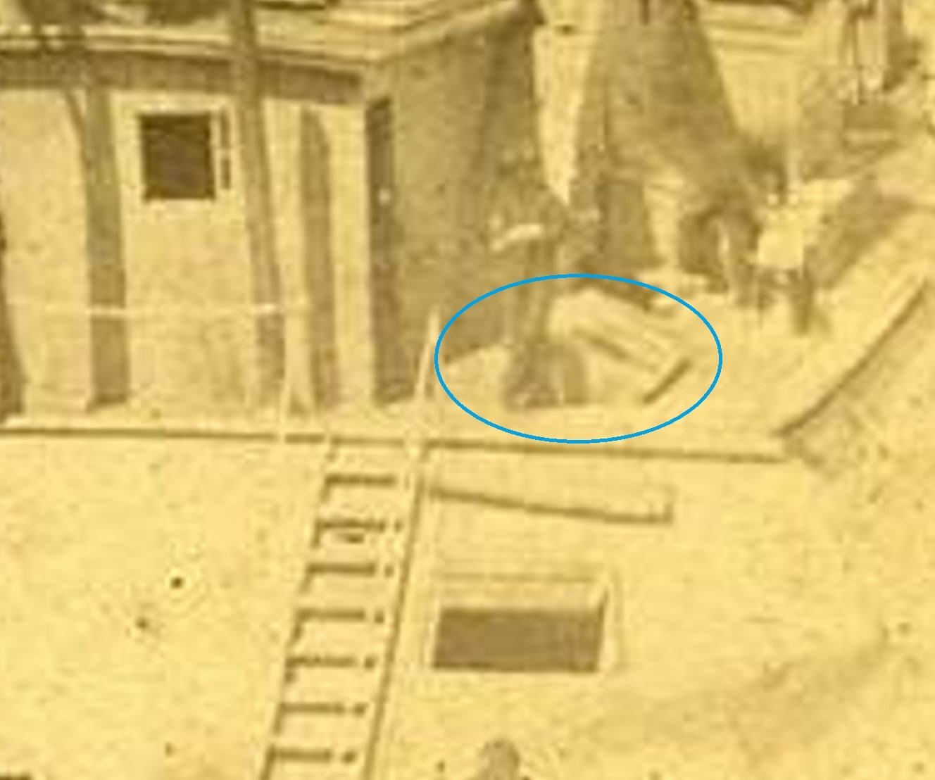
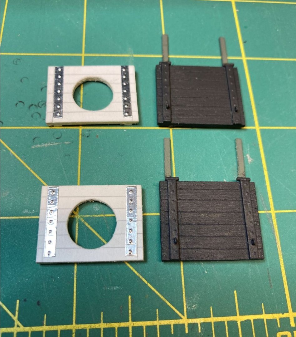
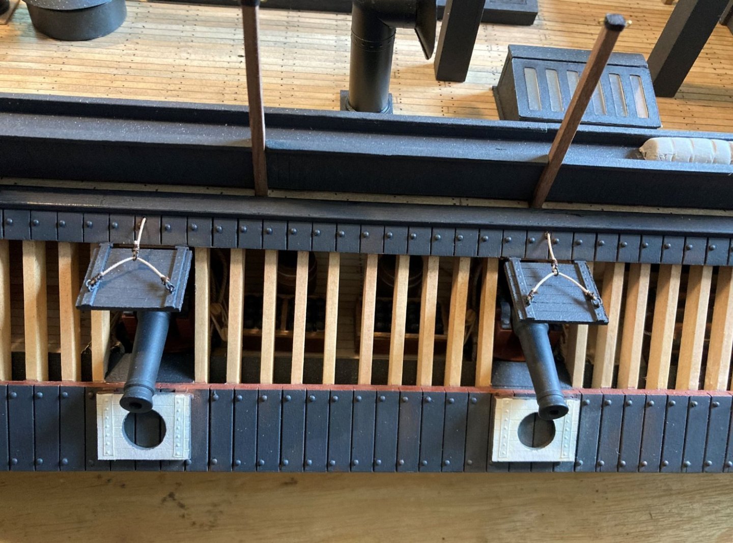
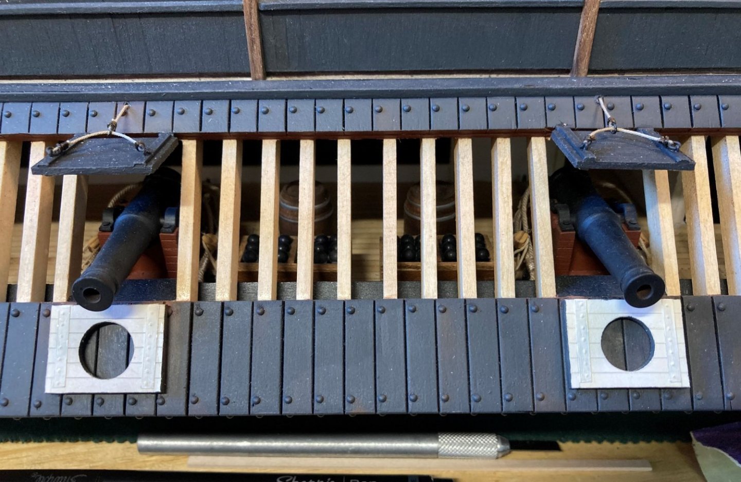
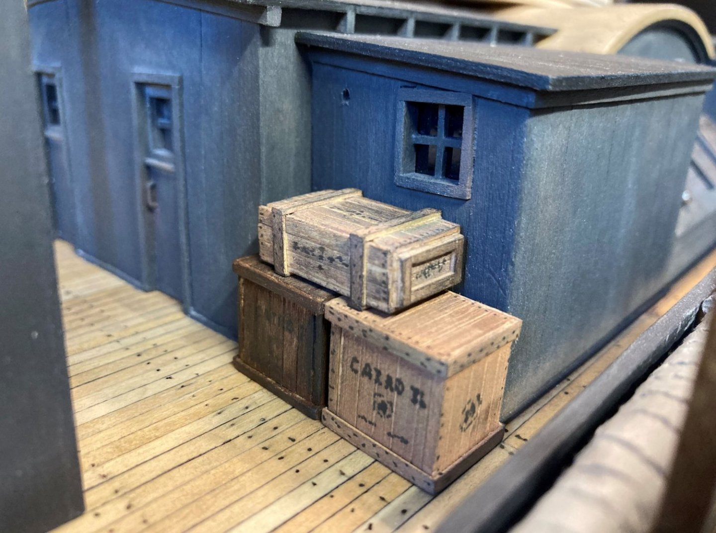
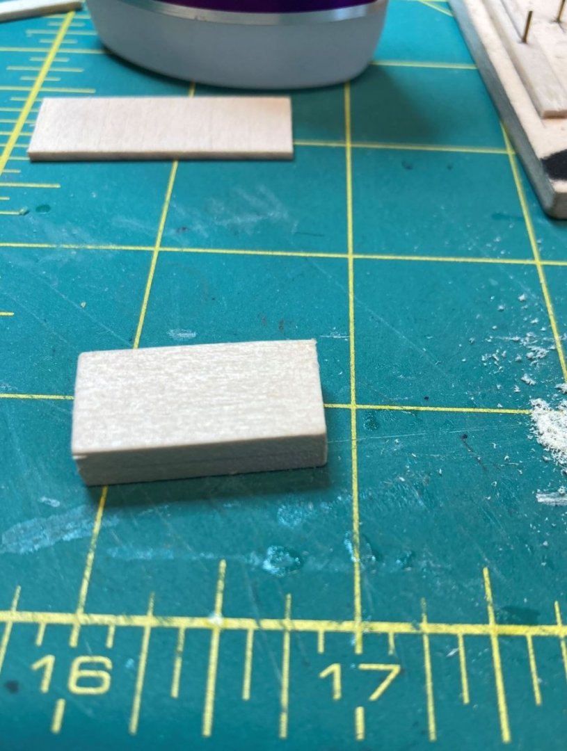
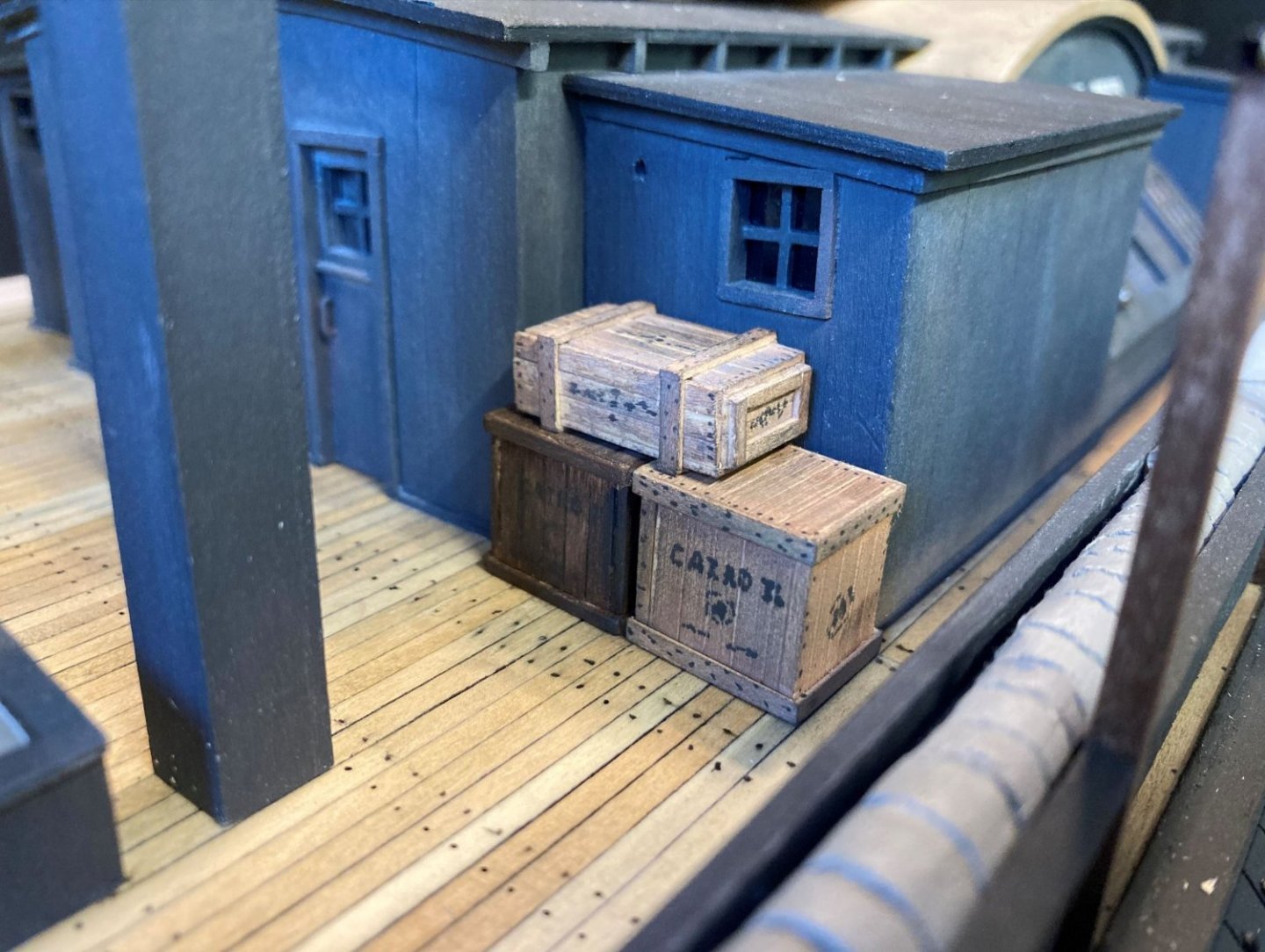
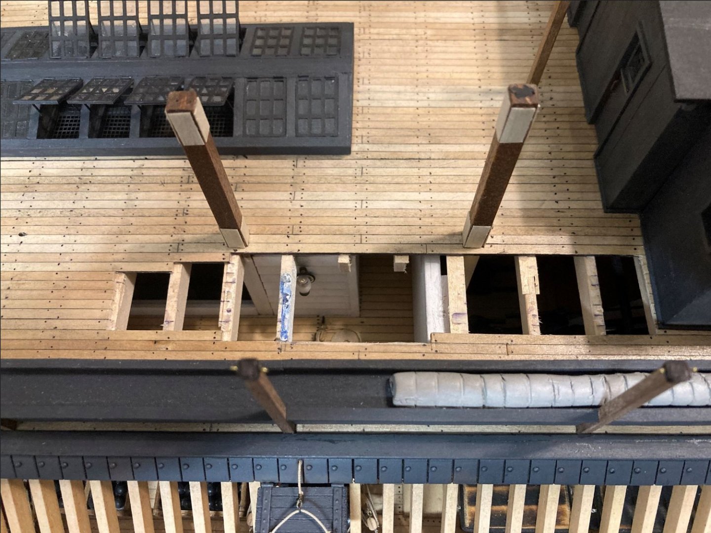
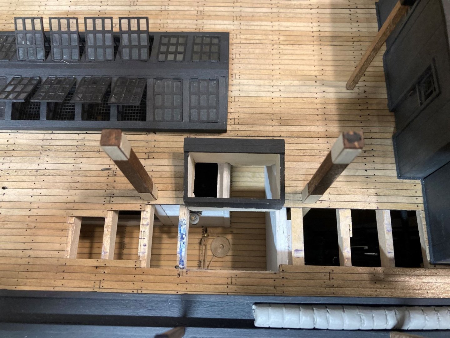
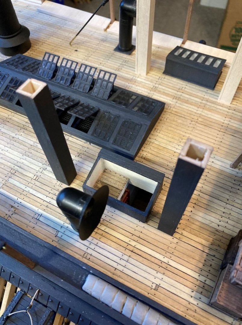
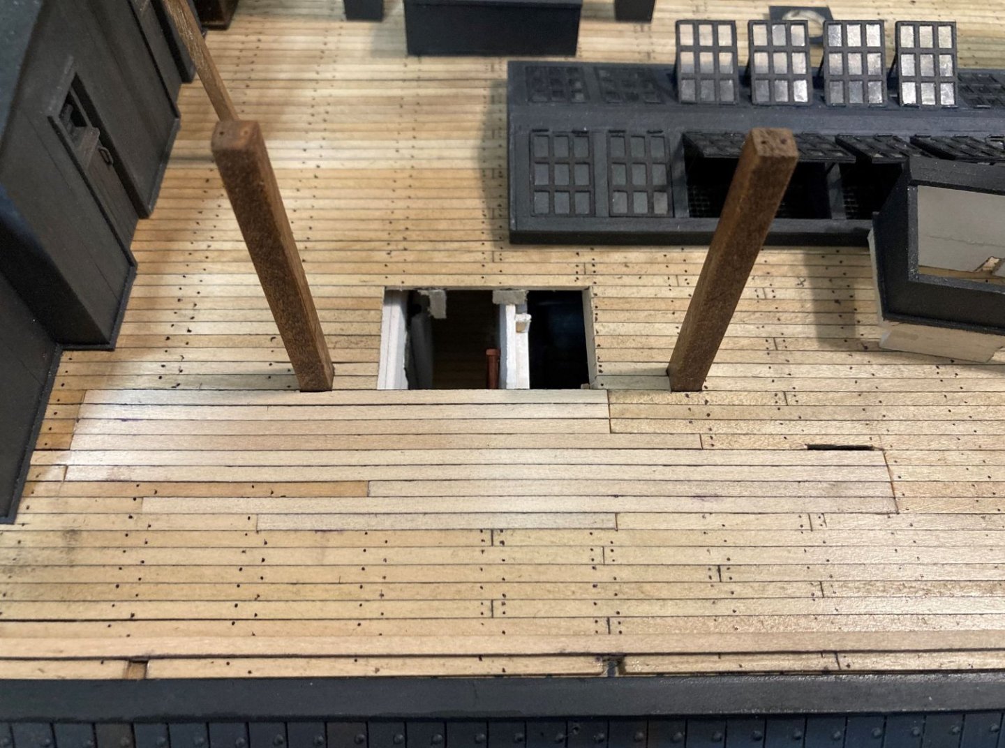
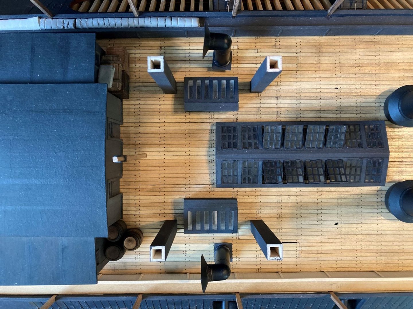
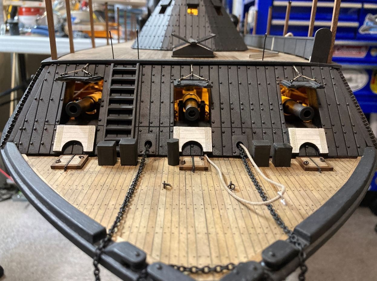
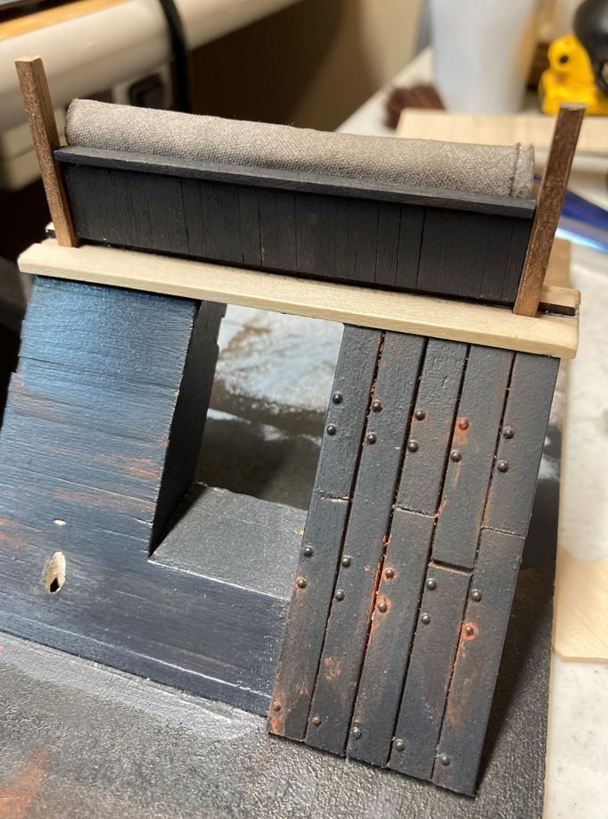
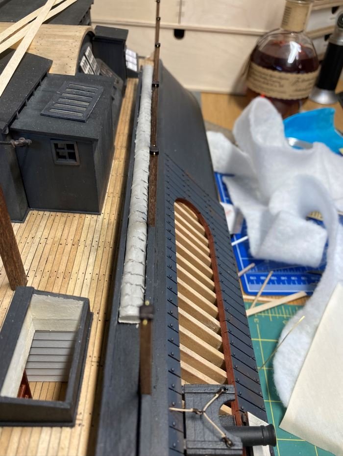
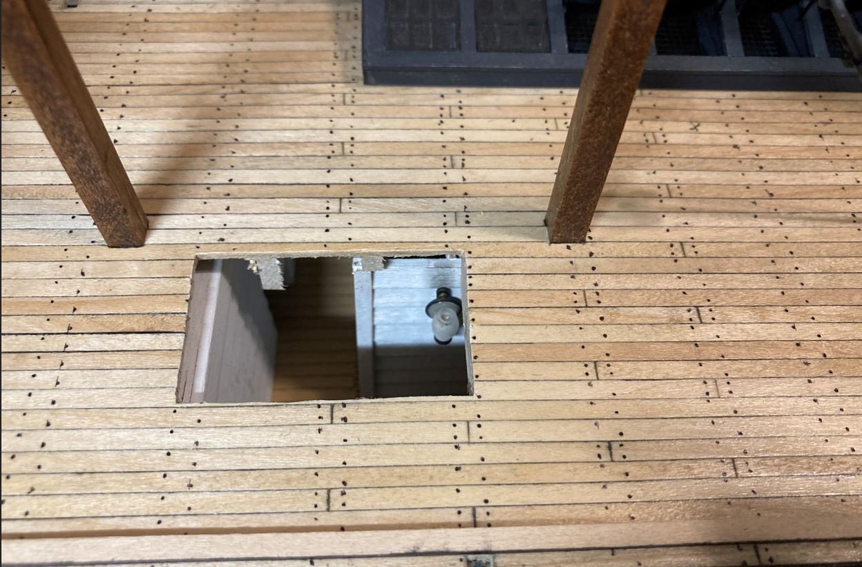
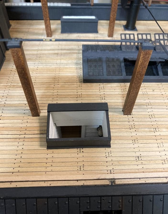
Hello again everyone, I have returned with another update. This time around it is not so much the progress made, but reworking areas that I found I built in error after more research and discussion. The first redo, were the port and starboard #3 & #4 gun ports. I had built all 13 gun ports the same, with the piercing in between the top and bottom doors. After my trip to Vicksburg and seeing the actual doors (not the ones on the display, these are wrong as well), I discovered that these four doors were designed slightly different in that they have a solid top door and the bottom door is pierced. This was also evident on the contemporary photograph of the Cairo, I had just not noticed it before. I guess I was too busy looking at other areas and overlooked this little detail. New doors. I cheated a bit on these, with the addition of the tabs on the top doors. There isn't a lot of contact points on the small hinges to glue the doors to the boat, so I placed the tabs underneath and filed out slot in the door frame to receive the tabs. This makes them a lot more stable against accidentally knocking them off while working around them, not to mention it helps hold the doors in the proper position. I did do a bit of new work just playing around with some deck furniture. I made up a few crates, to see how they would look. My plan is to populate the hurricane deck with several items. From many of the old photos you can tell that these decks were not clutter free, they were very busy. The beginnings of one of the crates. My first attempts all weathered up. Another redo were the hog chain posts. On the plans the posts are shown to be fairly narrow and sort and I built them according to the plans. After researching these more I found that they were more "beefier" and actually extended above the long beam that runs the length of the hurricane deck and provides a center ridge for the canopies. Not sure of what this beam is called. I didn't take any pictures of the construction of the new hog chain posts, but I constructed a square tube to slide over the existing posts and placed small shims on the smaller ones to fill in the gaps. In the next few pictures you can sort of see what they look like and how I built them. I haven't installed the caps on them yet or the hog chains themselves, I wanted to leave them off until I was finished working on the other rebuilt details of the deck. The last bit of rework that I did was the skylight/hatchways and aft funnels. There has been a lot of discussion on my build about this topic lately and I finally think that I have figured out how these were situated on the deck and used. First off, I believe that I was mistaken in the placement of the aft funnels. I have to agree with Johnhoward that in the old photo of the Cairo, the port aft funnel has been moved from it's normal place on the deck and set aside and that their actual placement is outboard of the hog chain posts and just aft of the forward ones as they are drawn on Ashley's HSR plans. Where I made the mistake was that I placed the skylight outboard of the posts instead of inboard of them. My initial thoughts on this placement was that the inboard wall of the skylight lined up perfectly with the exterior wall of the boiler room. This provided the perfect place for a ladder to go, enabling access in and out of the gun deck. However, moving the skylight inboard actually works better in two ways. One, it moves the ladder to the walkway area between the boiler room and the engine room getting out from directly behind the port and starboard #4 cannons. And two, it places the skylight halfway over the boiler room which allows for a standing platform to place supplies on while hauling it up and down the ladder to the holds. So I set out removing and replacing the port side deck boards in this area. (note the shims on the hog chain posts). New placement of the skylight. The area on the left side of the skylight is the overlap of the boiler room and where the platform will go. New planking going in. New planks sanded. Varnished. Platform and ladder installed. Funnel temporarily installed, deck nails added. All it needs is a bit of weathering and I should be good to go. Starboard side being reworked. Starboard side planks replaced. And both sides completed. I know that it is ugly right now, but the two areas where the deck board seams all line up will be covered with deck furniture so it will not be seen. Now I am 100% confident that I have this right. The funnels are where they are supposed to be according to the plans and the skylight/hatchways are installed per the photographs. The interior of the skylight/hatches may not be exact, but there is no photographic or documented proof that I have been able to find of how they were built, so this interpretation seems to make the most sense. Now on to finishing up the starboard side hammock racks and other deck features. Thanks to all for the likes and stopping by. -Brian


- 739 replies
-
- 19
-
-

-
I think I’ve said it before, but it bears repeating. It’s just amazing at what you are accomplishing at this scale! -Brian
-
Pat, Thank you for the info. It's hard to tell if doors were actually used on the City-Class gunboats for these areas since they were all (with the exception of the medical room) located in the hold. The medical room was supposedly located on the port side of the gun deck, across from the port engine in line with the junior officers quarters. These boats were designed with several hatchways spread throughout the floor of the gun deck to access the compartments from above. It is possible that some of these compartments had a passthrough to the next one and could have had doors on them. Some of the door knobs and locksets could have also come from the structures on the hurricane deck. There were at least four doors located here to access the storage rooms/showers. No telling if there were any other doors located within the structure since this section was all constructed of pine and had long rotted away before the salvage. A few years ago there was a LIDAR scan done of the boat and they put together a neat little "Fly Through" video of the hold area. It's pretty cool to check out, and will kind of give you an idea of how cramped the hold area was. -Brian
-
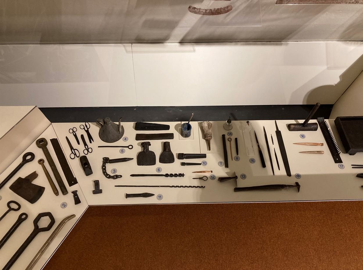
Roger/Eberhard, I would say that there was most likely a forge on board Cairo. Among some of the artifacts recovered were blacksmith tools and an anvil. Unfortunately I have not run across any mention of a forge yet, but with all these tools on board one would think that she carried one. There was a lot of activity on the hurricane deck during their down time, hence the reason for the canopies and the crew was known to have cooked some of their meals on makeshift stoves up on the hurricane deck, so it could be a possibility that the forge was located there and washed down river when she sank. This could explain the lack of additional ventilation from below deck. Just my thoughts. -Brian
-
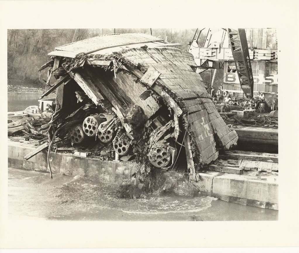
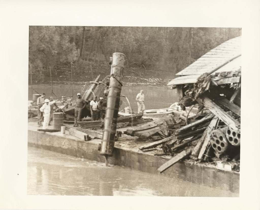
Johnhoward, funny that this drawing is more accurate than some of Doug Ashley's, at least in the fact that they got the guy anchor point located in the correct places. Would you happen to have a full picture of these drawings to share? I'd like to get a better look at the overall drawings to see how the SLCWM interpreted the design. This is a tough one. During the salvage there were numerous door knobs and locksets recovered and one almost fully intact door. The door is believed to have come from the captains quarters, however, there is no explanation of the other door knobs and locksets. Where did they come from? Could these have been from the junior officers quarters? Some descriptions of the junior officers quarters are they were made of canvas walls that could be taken down expediently, so it seems that there would be no need for doors there. My other thoughts are there had to be other doors somewhere else on the ship, Possibly access doors from the gun deck to the boiler room or engine rooms? There is written documentation that when the Cairo was refitted with the railroad irons on her forward casements, the crew also used some of the same materials to fortify the boiler room walls on the gun deck to prevent a catastrophe similar to the one on board the Mound City. Since there were walls along the sides of the boiler room, would there be the possibility of doors along these walls allowing access to the fire room from the gun deck as shown in Ashley's plans? if so, this could account for at least two other doors. Where were there others? The walkway between the boiler room and the engine room was the location of where one of the cuts were made by the salvagers when they decided to bring the boat up in three sections, so not a lot of this area survived. Personally I believe that some of the documentation of this area is left to interpretation by Ashley. It was also through this area where the "Doctor" pump was lost and the skylights & aft funnels were as well, so there is no telling what else fell out when this section was brought up. Some photos of the center piece of the boat being recovered showing the aft side of the boilers and the steam drum coming up. In the first photo, you can make out what looks to be a solid deck running behind the boiler tubes, Not sure if this would be that walkway or not, but it is possible. The skylights and the aft funnels would have be located in the area that is sitting on top of the barge, These pictures bring tears to my eyes sometimes. Man did these guys make a mess of the recovery. -Brian
-
That would be an extremely nice addition, but you are correct sir, a tad bit too rich. -Brian
-
Keith, take all the time you need. We are here for you and you will continue to be in our thoughts and prayers. -Brian
-
Eberhard, your patience on these small boats must be commended. It was all I could do to maintain my sanity making my four ships boats at 1:48 scale. At 1:160 scale they would have to carry me out in a straight jacket drooling and babbling to myself. Amazing work. Looking forward to the next installment. -Brian
-
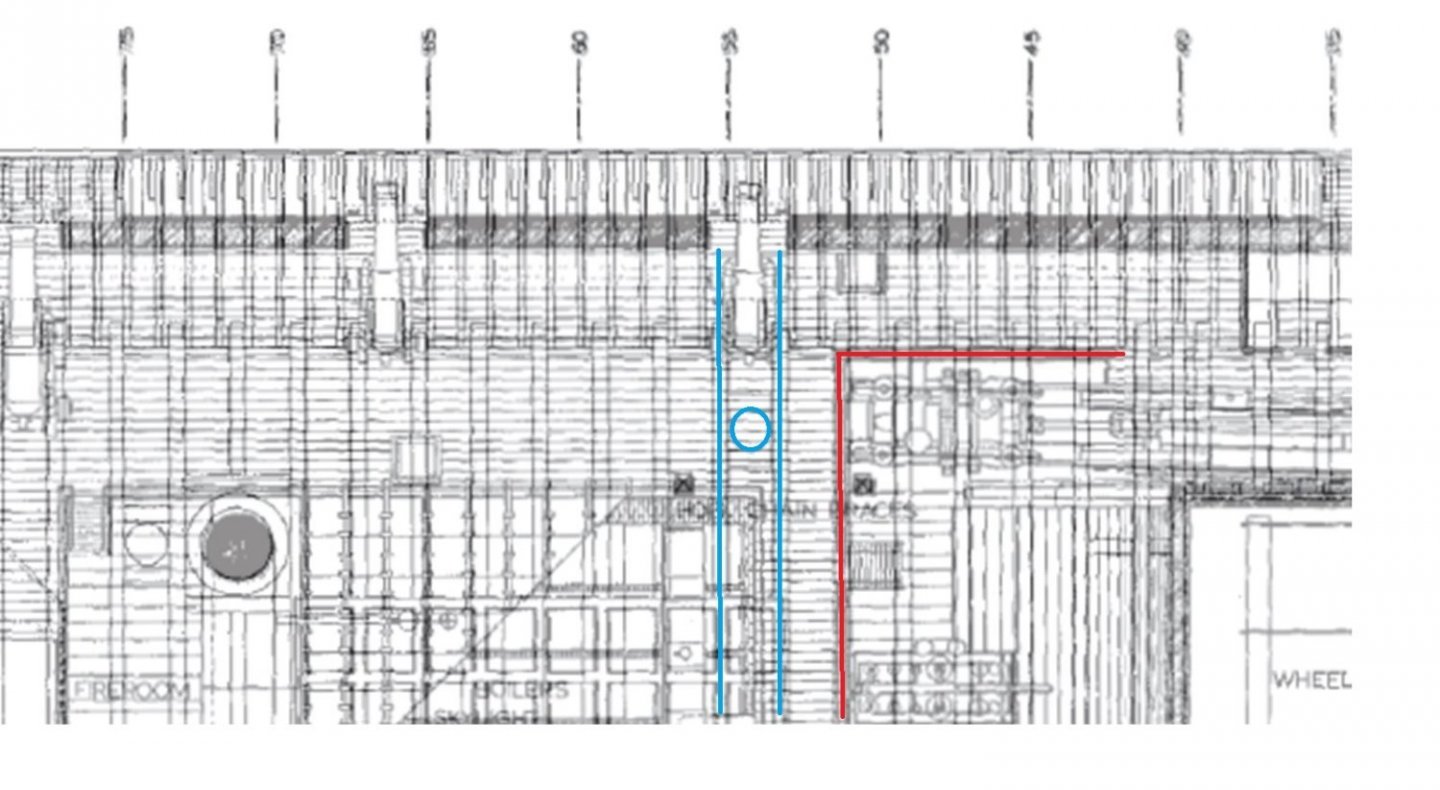
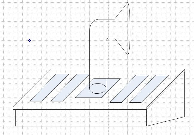
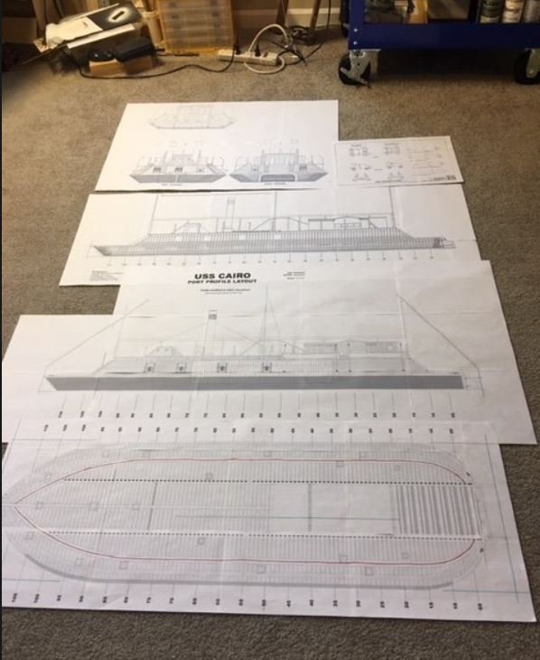
Johnhoward, Oh how I wish someone would have taken aerial photos of these boats. It sure would make building them a whole lot easier. However, then it would take all the fun out of researching and interpreting what information we have to make the best representation possible. Not to mention we would not be able to have these great conversations about them. This option had crossed my mind. I had thought that the funnel tube through the deck could be located inside the hatchway, putting it pretty much in line with the plans. The main reason for not taking that route was the fact that the door to the hatchway (skylight) looks to be closed framed with long narrow glass panes in it, Now, on the picture of the Cairo that does show this skylight, the middle section is blocked by the hog chain post and a crewmember so there could possibly be a pass through area where the funnel could be installed when the skylight is closed. Doesn't seem real efficient, but it could be a possibility that they could have the funnel in the location shown on the plans, they remove the funnel, open the skylight, and use the hatchway to load supplies, then put everything back together when done. A simplified drawing of this possibility. I agree with this consideration 100% that they would indeed provide perfect ventilation for the engines. The issue I see with this is, although the funnels are directly in line with the engines, they are too far forward going by their location on the HSR plans. I took the Gun Deck and Hurricane Deck plans and overlaid them in a CAD program (see picture below), and given the location of the framing shown on the plans, in relation to the engine room, the funnels would have been roughly 10' forward of the forward most part of the engines. If the interpretation of the plans are correct, they show a wall structure surrounding the engine room on the forward, port and starboard sides, which would render these funnels ineffective in removing heat from the engine room given their location. If this wall structure does not exist, they may be somewhat effective at removing some of the heat, but the majority of the airflow through the Gun Deck would be rearward (while underway) so placing the funnels forward of the engines to remove that heat seems like a design flaw. I have to ask though, the drawings that you have on your last post. Which ones are those? I have the Ashley drawings, the Bob Hill Plans and the ones from the HSR, but I don't believe that I have seen those. They have a great diagram of the guys for the chimneys and masts and show their accurate locations anchored to the hog chain posts and stanchions as opposed to the other drawings that have them anchored to the Hurricane Deck. -Brian
-
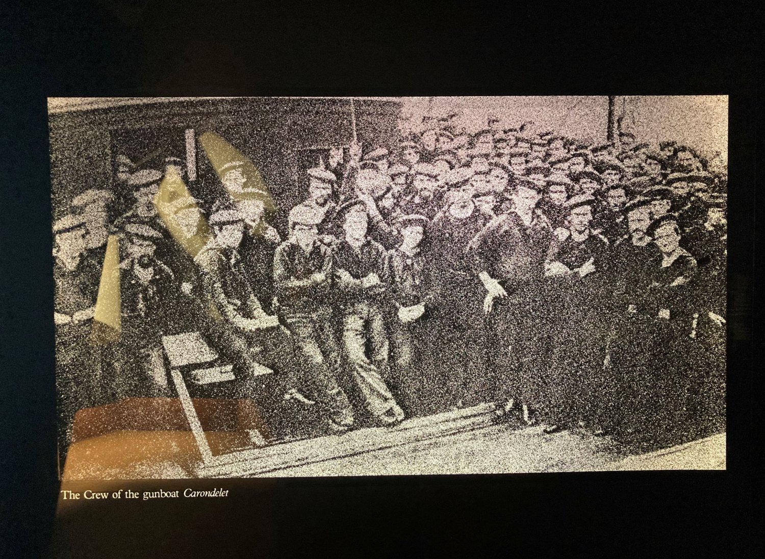
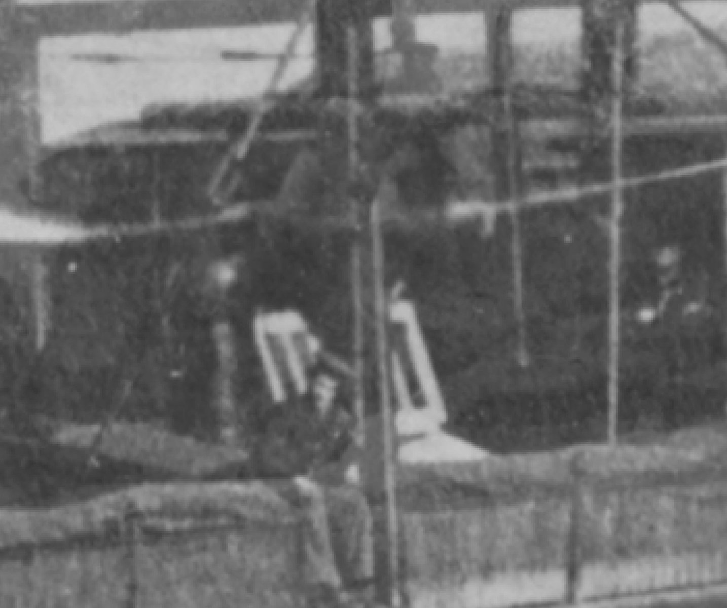
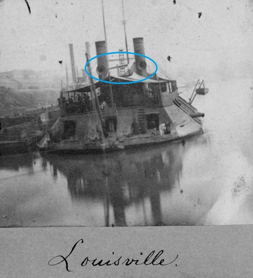
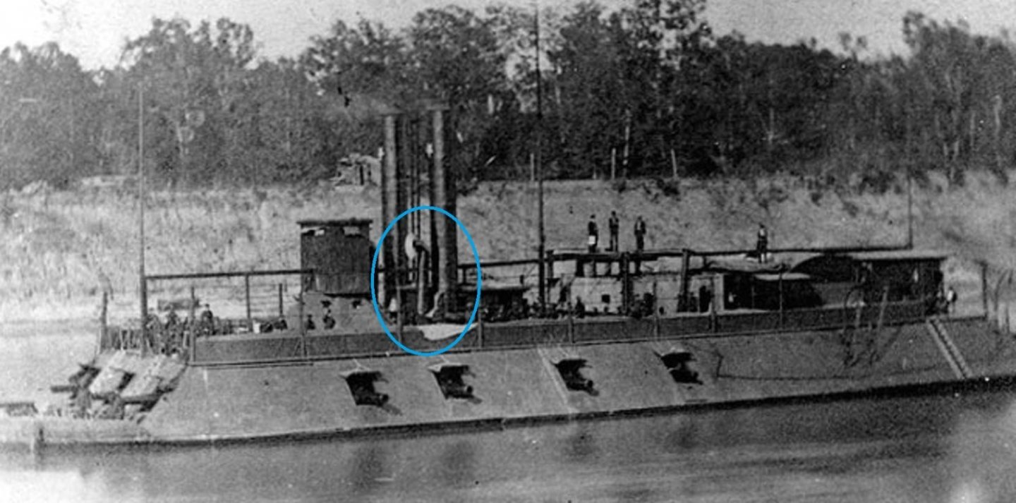
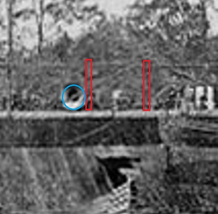
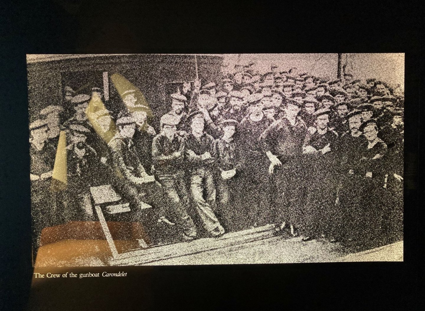
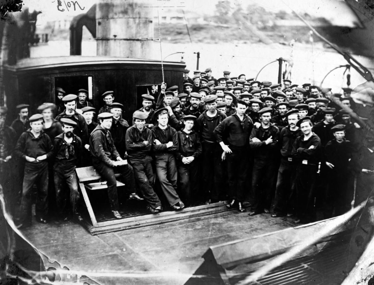
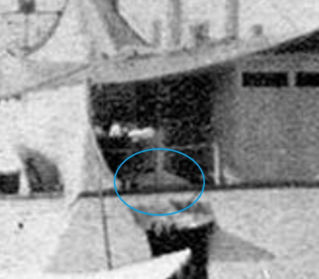
Thank you all for the likes and comments. Eric, not sure if Hallmark is hiring or not, but you might make it at as a greeting card writer as a second job. 😁 Johnhoward, You are most welcome. The photos of the tent that you attached are actually a diorama display in the Welcome Center at the park entrance. This display shows as a representation of the standard field tents used during the siege and not indicative of the junior officers quarters onboard the Cairo. I had thought that I had taken some pictures while we were in the Welcome Center, but I guess I didn't. My wife took several pictures of our tour as well, but I haven't downloaded those picture from her phone yet. Once I do, I'll peruse through them and see if she got a picture of the placard on this display. I'm not sure that I can truly explain the difference between the Ashley's NPR drawings and the photos, other than that back in 1981 they didn't have the luxury of the internet which made it a little harder to look up information as easy, and much of the earlier documentation was based off of old, limited information that they were able to obtain and what was salvaged from the Cairo. Based on my conversation with Ray at Vicksburg, there have been many details, that after further study, have shown to be in error. In the 40+ years since the HSR and drawings were published a lot of study, research and technology has helped identify certain areas that were incorrect on the initial survey of the wreckage. Hopefully I don't sound like I am beating up on the museum, that is truly not my intention, but I did discover that there was a error with one of their display facts. They have a side room from the main gallery of artifacts, a little alcove that gives a brief history of the City-Class gunboats. On one of the displays they show what is labeled as the crew of the Carondelet. At first I thought, I need to locate a better picture of this since it might be a great study picture to hopefully get some deck details from, and since the photo in the museum was a bit grainy. I managed to find a high resolution version of the photo and soon discovered that this was actually the crew of the USS Choctaw. I wonder if the museum knows of this error? This is a snapshot from the museum display. Original photograph from the Naval History and Heritage Command website. (they do list these photos as public domain and allow their reuse). If you look closely at the photo of the St. Louis you attached, you can make out what appears to be the same skylight/hatchway structure between the hog chain posts (outlined in red below) as the Cairo, and the funnel looks like it is in front (outboard) of this structure. On the old photos of the Cairo and the Pittsburg the funnels are located forward of the hog chain posts and outboard of them. Granted, since these photos are not dated, there could have been several modifications and repairs done to these boats during that time. The Cairo photograph has been well documented that it was taken shortly after her commissioning in January 1862, so she would not have been modified too terribly much. This is evident by the missing railroad irons on her forward casements (added May 1862) as well as the additional reinforcements to the forward side of her pilot house and viewport covers (added March 1862). These two photos are what I based my location of the funnels on. However, the Cairo's aft funnels could have been located in the same position as the ones on the St. Louis and, like you mentioned before, removed temporarily for some reason or another, and stood up in it's location in the photo. The only doubts I have about this would be that there was not a lot of room between the skylight/hatchway and the hammock rails to walk around and that two different boats appear to have them in the same location. St. Louis skylight/hatchway Pittsburgh Pittsburgh's port hog chain posts shown in red with the aft funnel located forward of the posts. I would think that there could be some slight variances in the construction of these boats and could constitute the differences in the funnel placement. Many of the structures on the Hurricane deck were made from pine, including the deck boards (on the Hurricane and Gun Decks). Since this area was exposed to the water the longest after she sank, and pine not being a very durable wood when exposed to water for any length of time, a lot of this area rotted away before the salvage. This could also explain why they are not shown on the 1968 drawings or the 1981 HSR. But in my opinion, I do believe that the structure circled below on the Cairo photograph is a another hatchway to the Gun Deck and is something that was not included when they published the HSR. I wasn't sure if the next photo is the one that you are referring to, but it is the one that I referenced in an earlier post of the Mound City forward funnels, However, after further study, I don't think that the funnel is leaning against the chimney, but rather looks to have been extended upward with somewhat of a lean to it. The same modification looks to have been done on the Louisville as well judging by the second photo. Mound City Louisville Thank you all again for stopping by. -Brian

-
Ok, now that is one of the more interesting builds. Great patience and great job!! -Brian
-
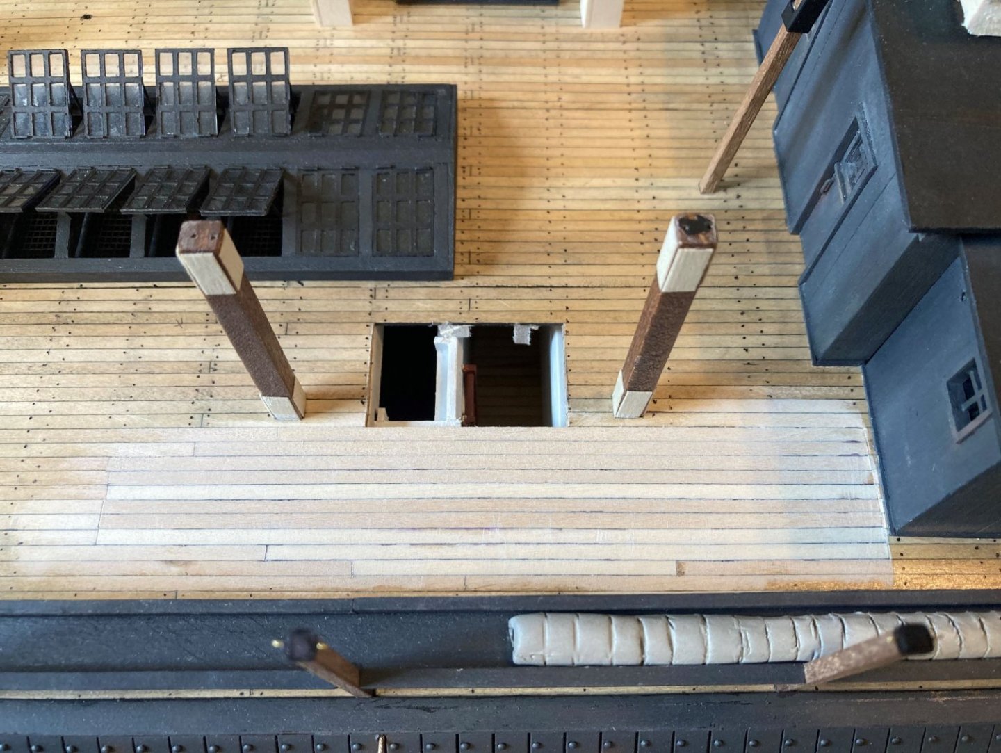
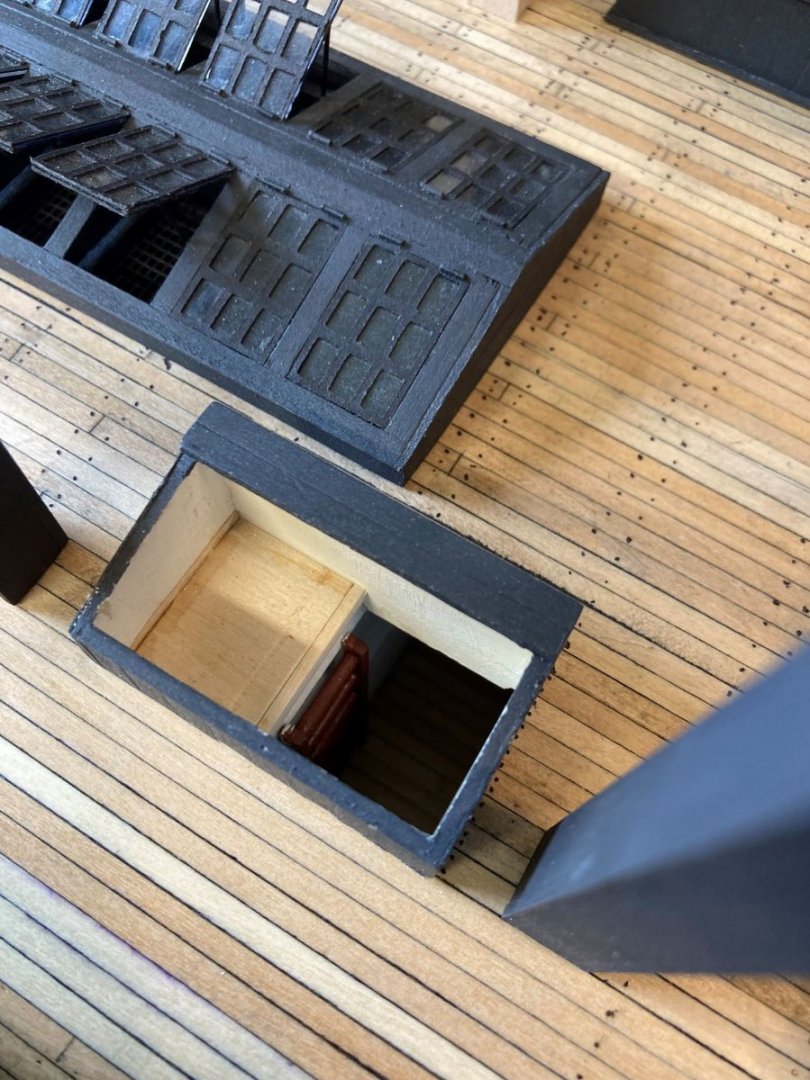
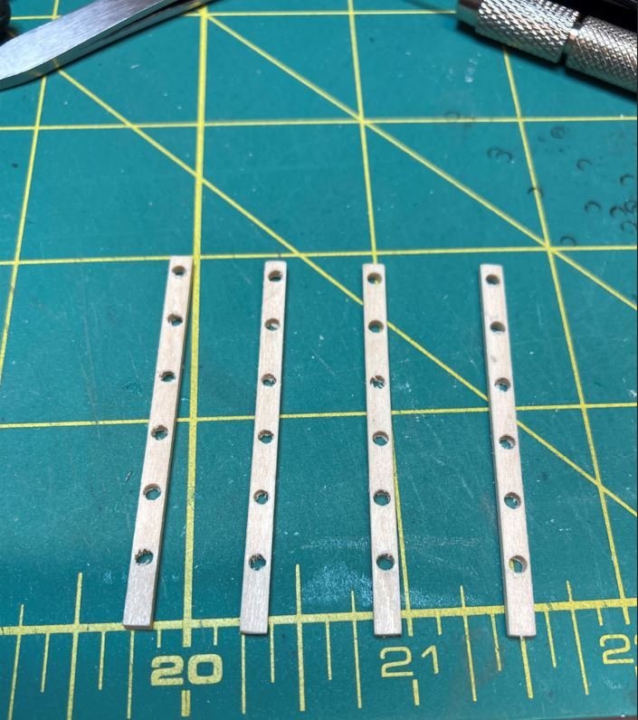
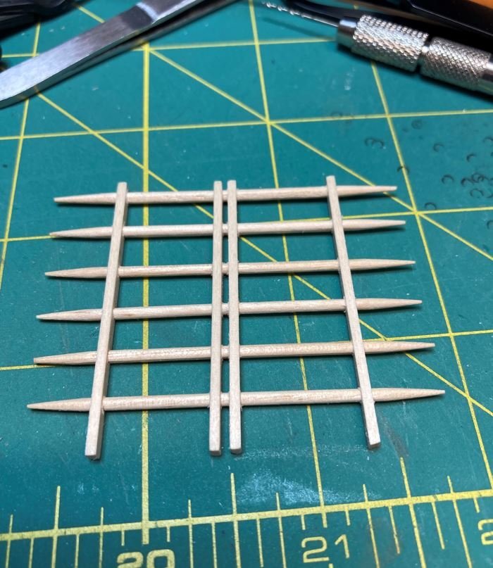
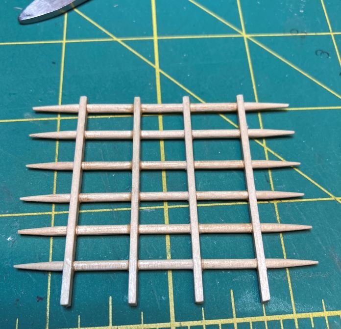
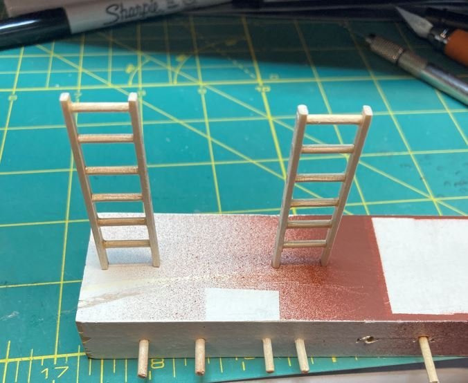
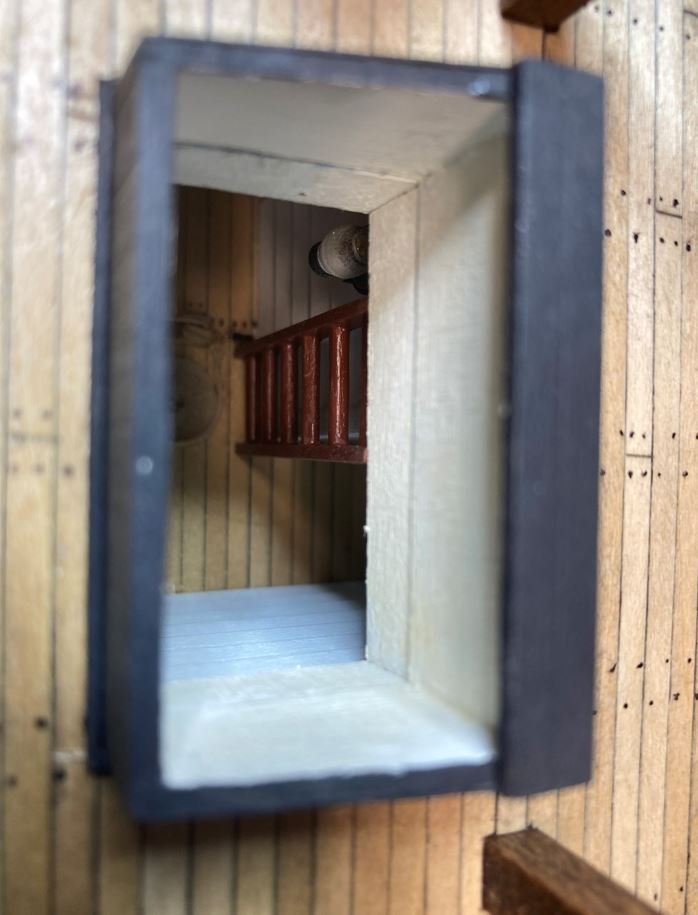
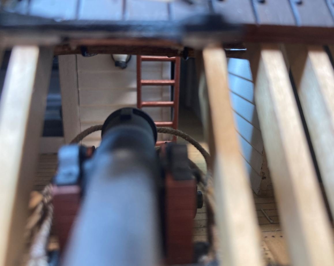
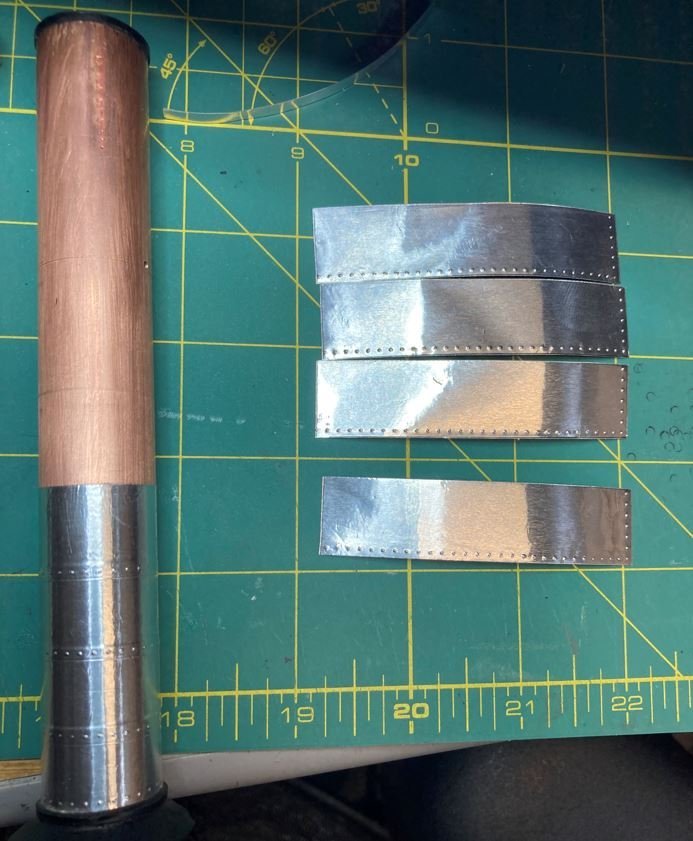
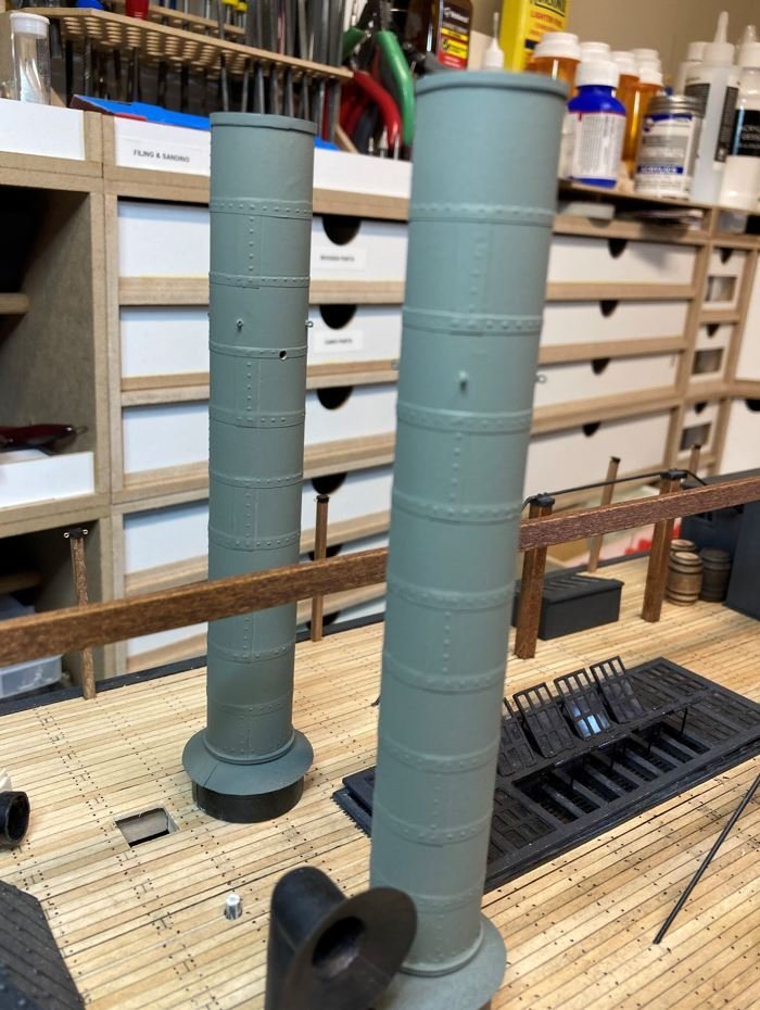
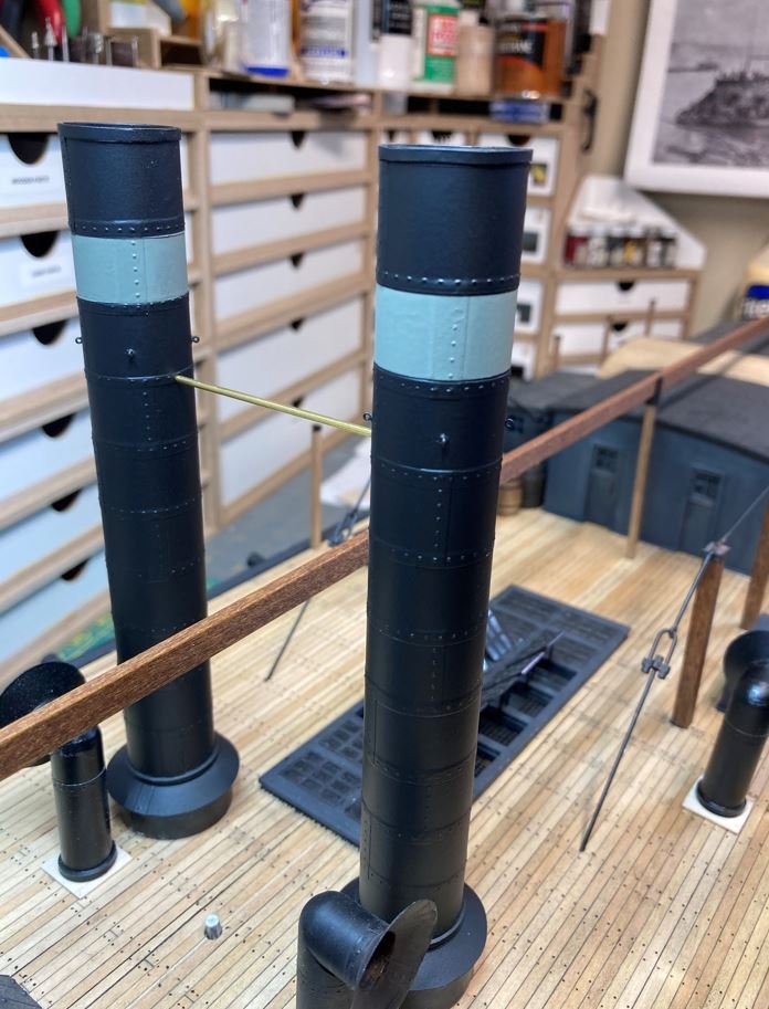
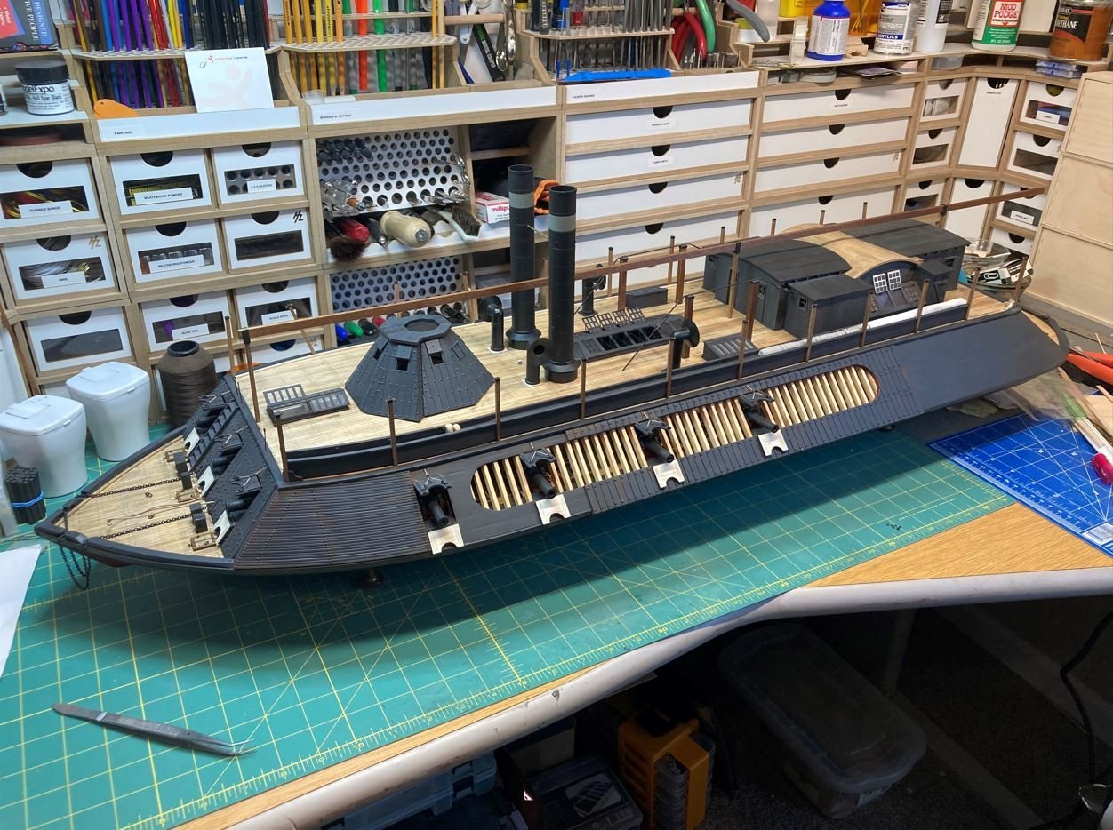
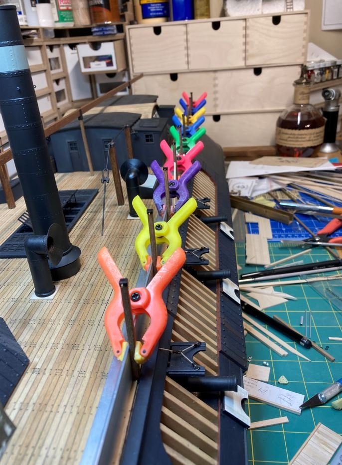
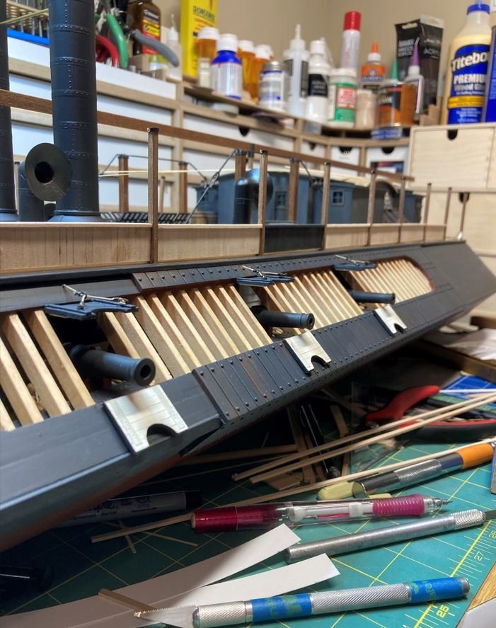
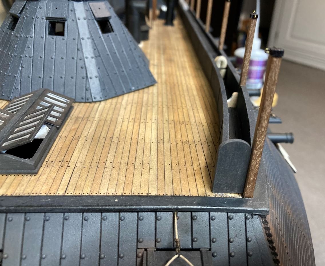
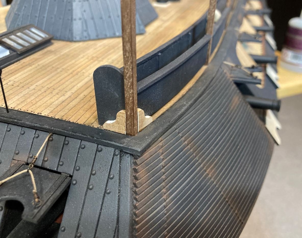
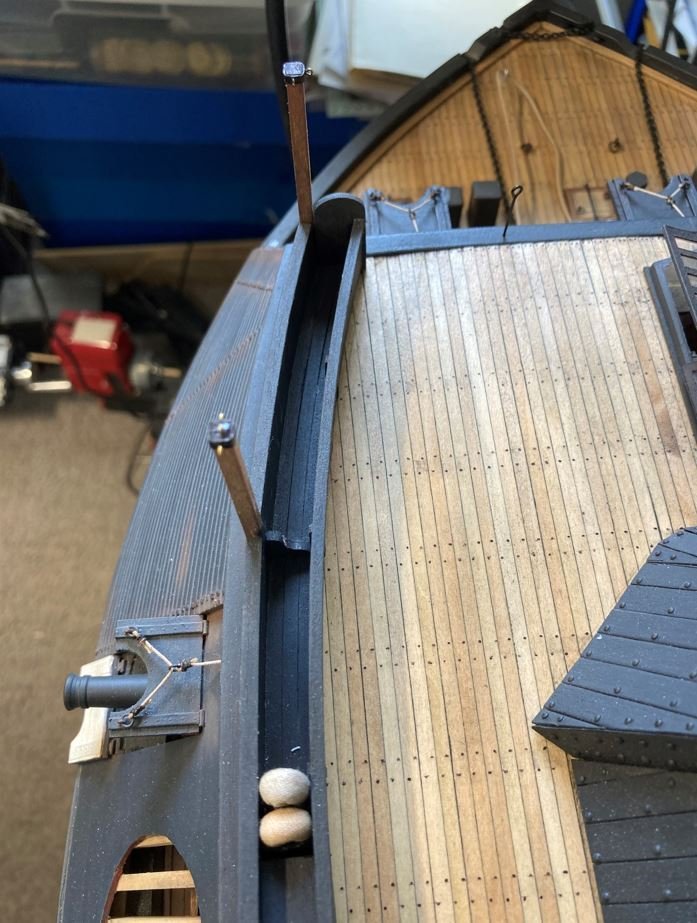
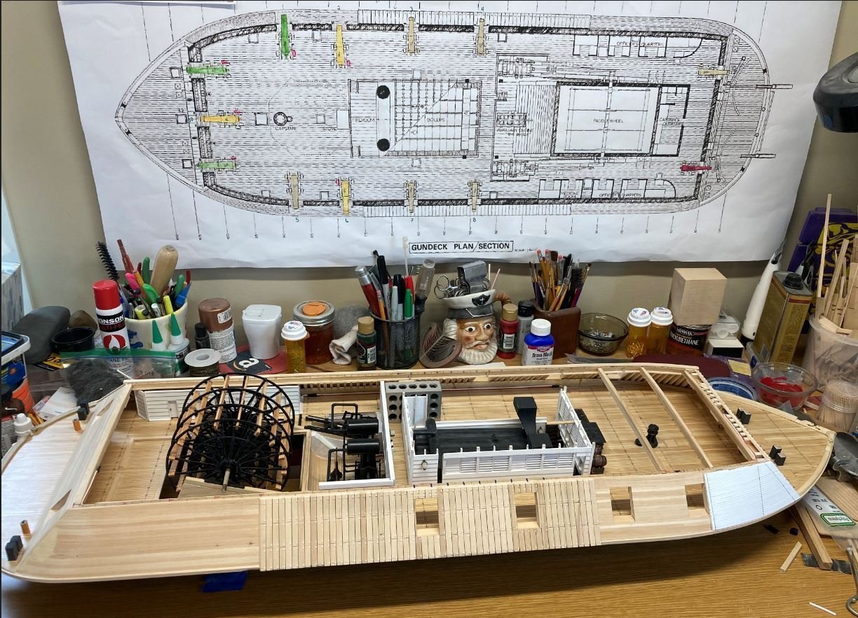
Hello again everyone, It's hard to believe that I have been working on this build for two years now. My how time flies. So for my second anniversary I though I would post a brief update. I finished up on the hatchways between the hog chain posts. I am 99.9% confident that this is what these are, and where they are located from the old photograph of the Cairo. I previously completed the Port side hatchway and finished up the Starboard one. Once these were completed, I started construction on the ladders. I used the same technique and style that was used on the ladder to access the pilot house, just a standard wooden ladder with round rungs. First, holes were drilled in the side support. I used toothpicks for the rungs and pieced the whole thing together to get the rungs evenly spaced on both ladders. Next I got the spacing for the width of the ladders and glued the rungs in place. Finally, I separated the two ladders, glued them to a scrap piece of board and painted them up. I forgot to take a picture of them painted, but here are some of pictures of them after they were installed. Next up, after more research I found out that I didn't get the chimneys built correctly. Due to an error in my math, I had the spacing of the segments too far apart. So I stripped everything down and rebuilt them using the correct measurement this time. I triple checked my math this go-round. I used the same method as before, using aluminum tape and a ponce wheel to simulate the rivets, then wrapped them around the 3/4" copper tubing. Once they were wrapped, they were painted with a special primer that helps paint adhere better to aluminum, another step that I forgot on my previous attempt. Finally, the black paint is applied and the signature Gray Band that was assigned to the Cairo. Finally it was on to the hammock racks. I used my handy dandy little mock up to get an idea as to how I wanted to build these up. Since it was confirmed that the Cairo's hammock racks were indeed constructed of wood from my conversation at the museum, this was how I was going to construct them. Satisfied with they way they looked on my mockup, it was on to adding them to the Port side deck. Outer walls going on. Each of the stanchions have a knee brace pointing inboard to support the rails as well as support for lateral movement from the masts and chimney guys. Getting everything straight. One of the internal knee braces. Hammock rack end cap (or tombstone as I like to call it) installed. External knee braces in place. I started to work on the simulated stowed hammocks that were going to be covered. I was using some DAS Clay to form the shape of the hammocks and was going to cover that with some muzlin with a coat of paint and weathering, but it just wasn't coming out the way that I'd hoped it would. So I am going to play around with a few other ideas and see what looks best. I was messing around with the lighting and a few other things when I snapped this shot. I just thought that it looked cool, so I included it. Finally, in celebration of two years worth of work. Day 1: Day 365: ...and Day 730: She's starting to come together. I did clean up my bench somewhat for this picture, it would have been way too embarrassing to post a picture of it sitting in the clutter. Now on to building the hammock racks on the Starboard sides and the aft skylight/hatchways. Until next time, thank you everyone for stopping by and all the kind comments and likes. Everyone stay safe and healthy. -Brian
- 739 replies
-
- 16
-
-
-
Keith, I am so sorry to hear of the passing of your son. We will keep you and your family in our thoughts and prayers. -Brian
-
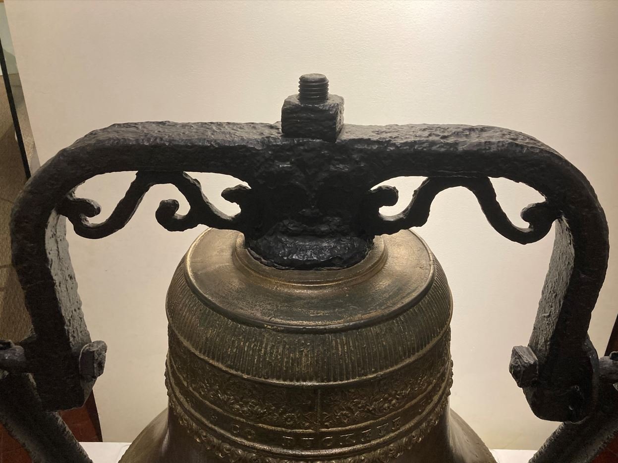
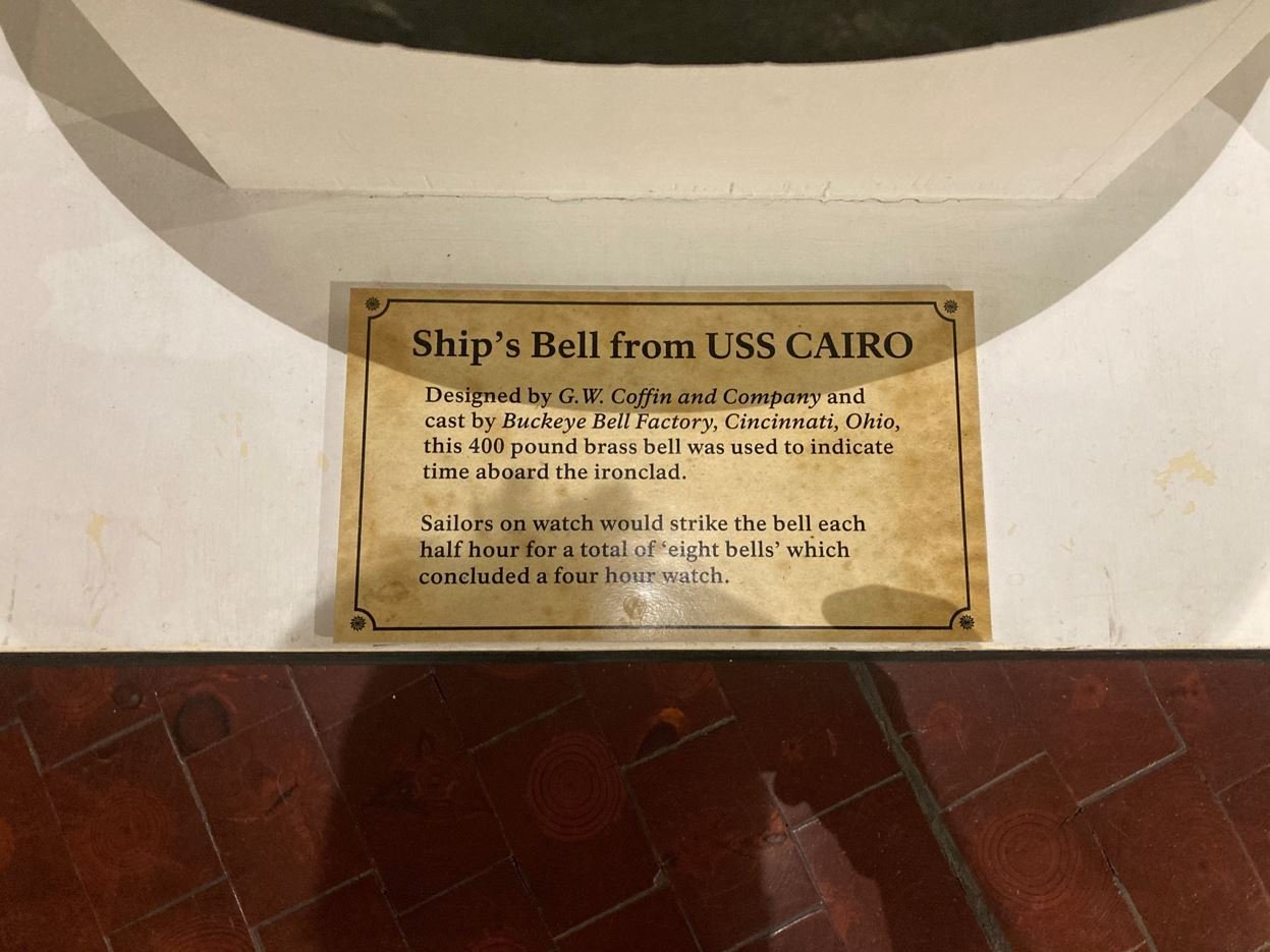
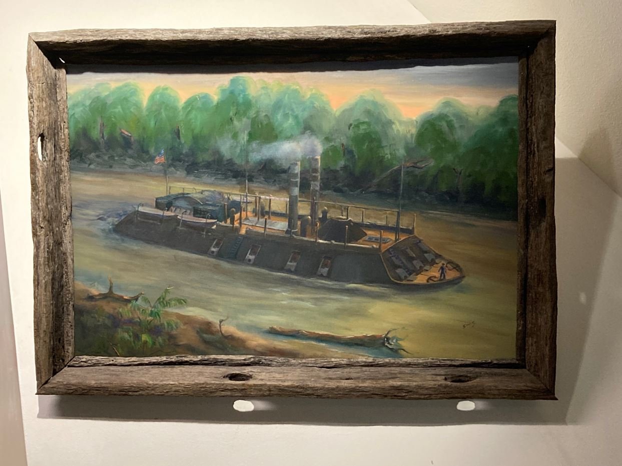
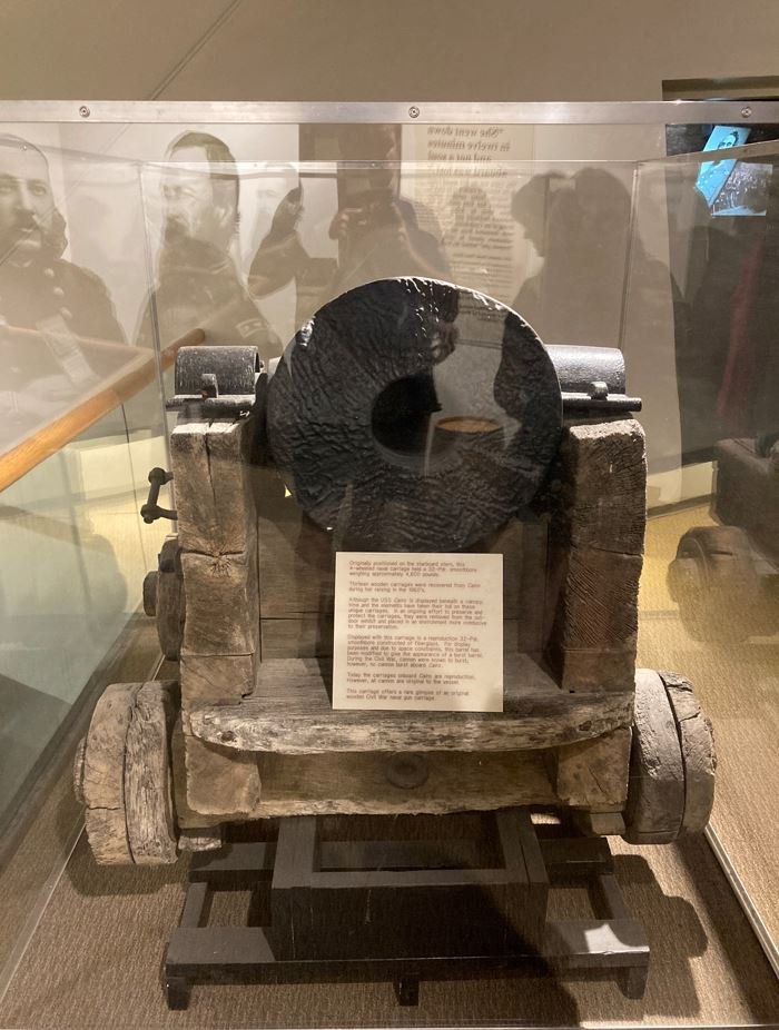
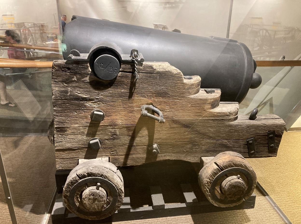
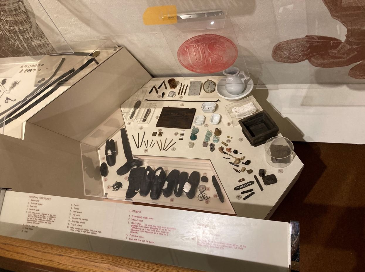
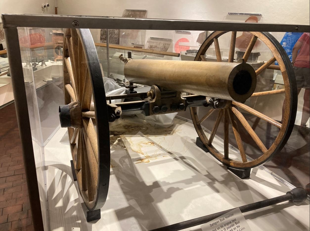
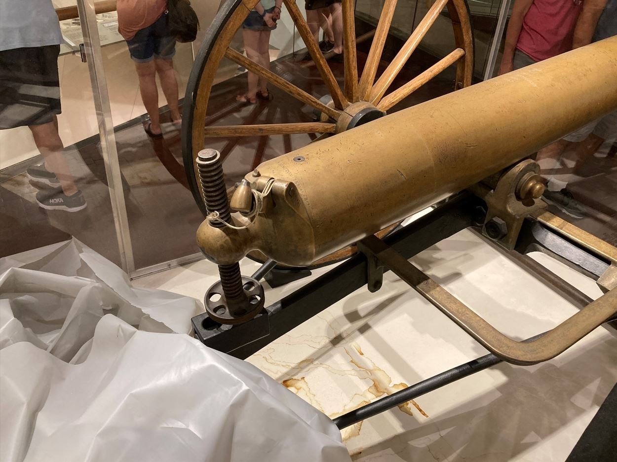
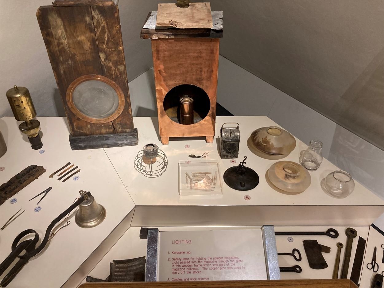
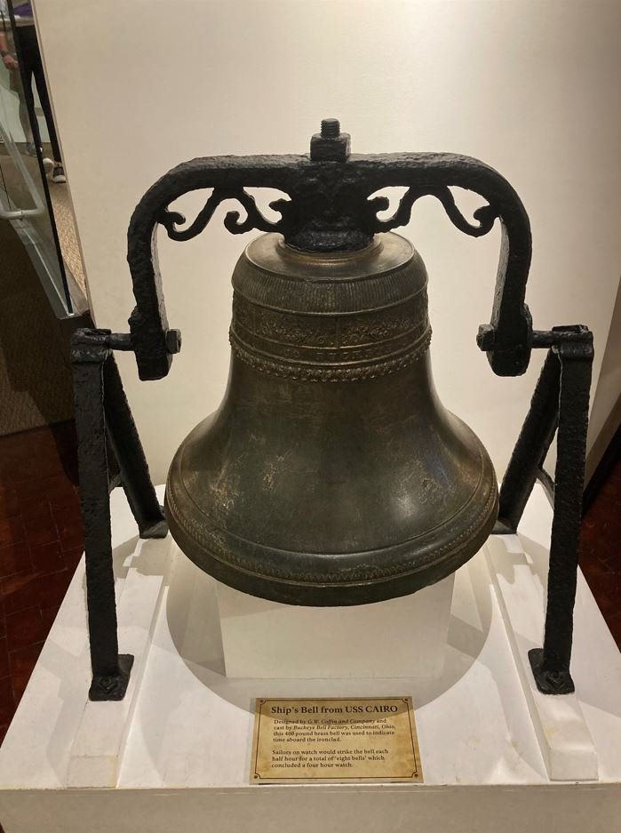
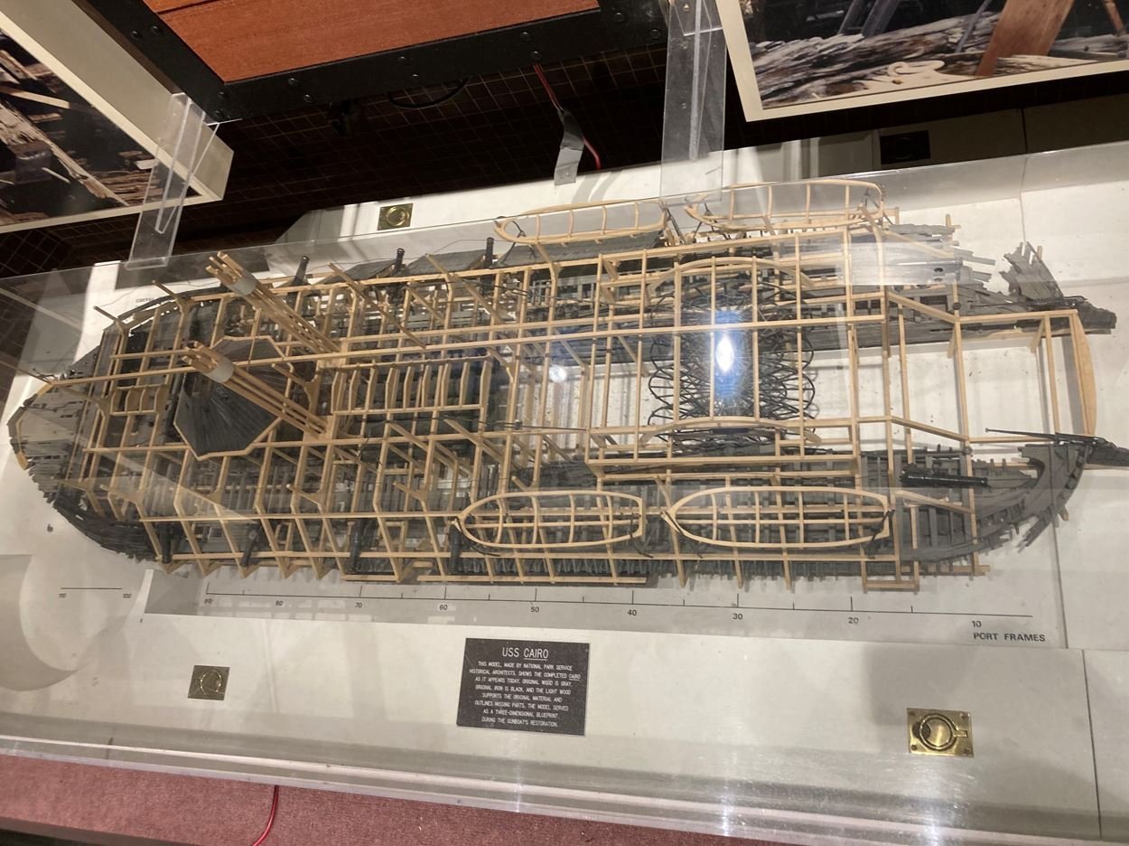
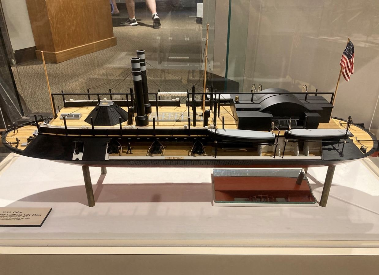
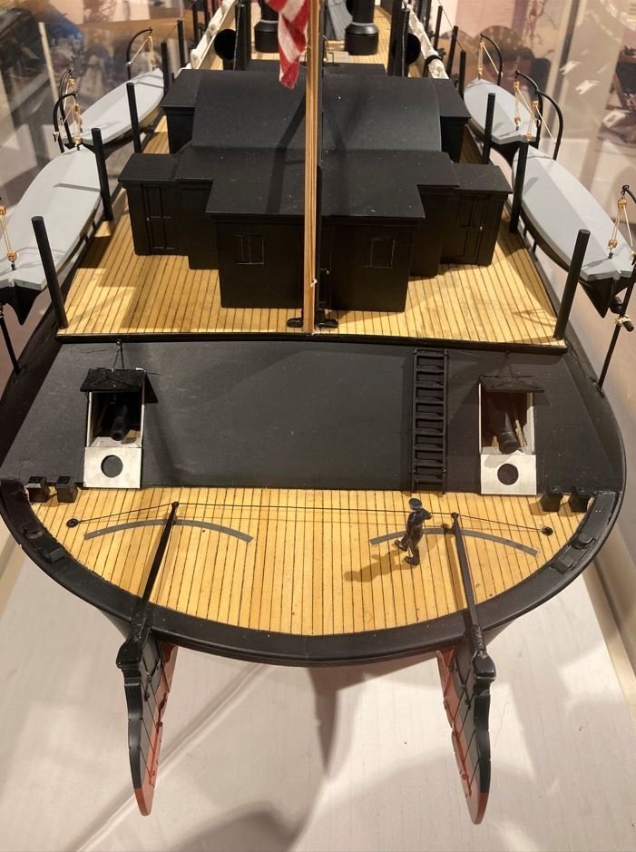
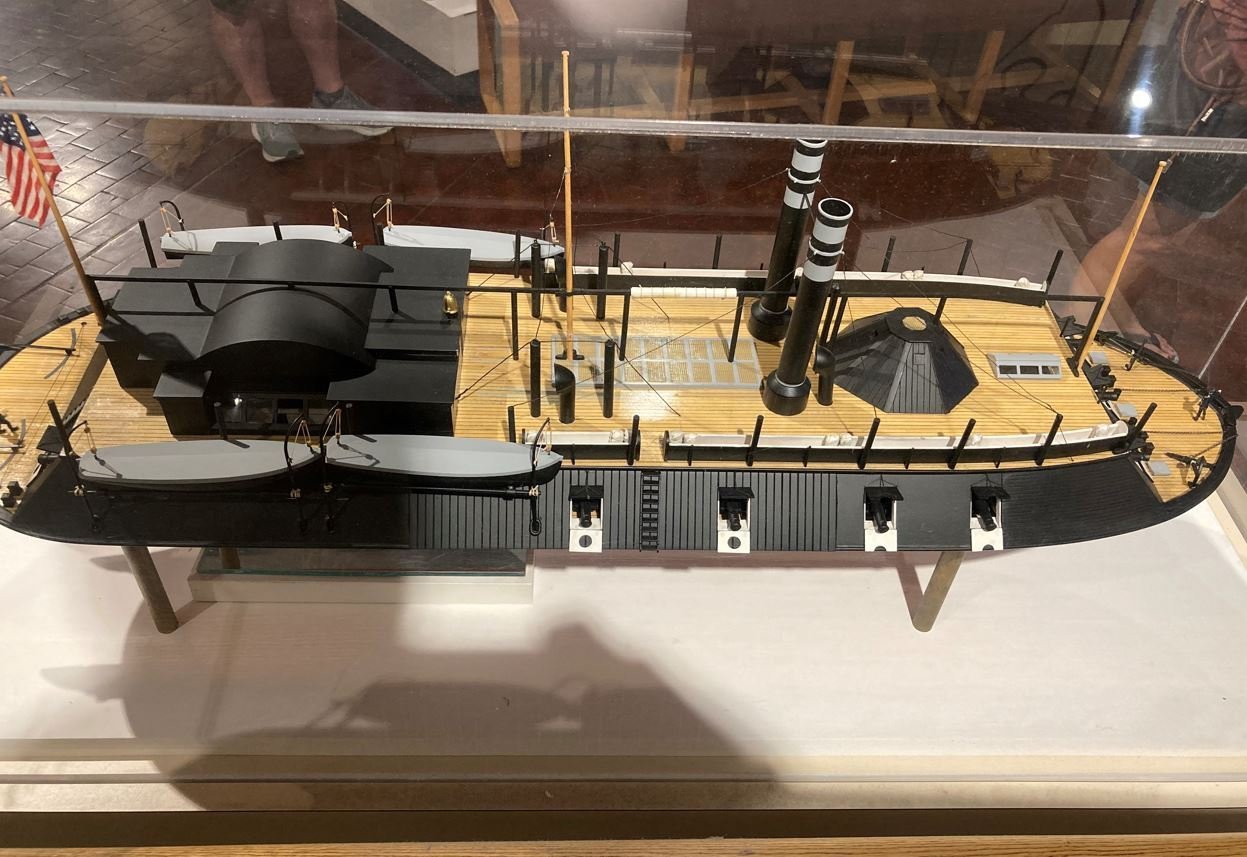
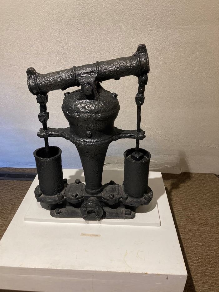
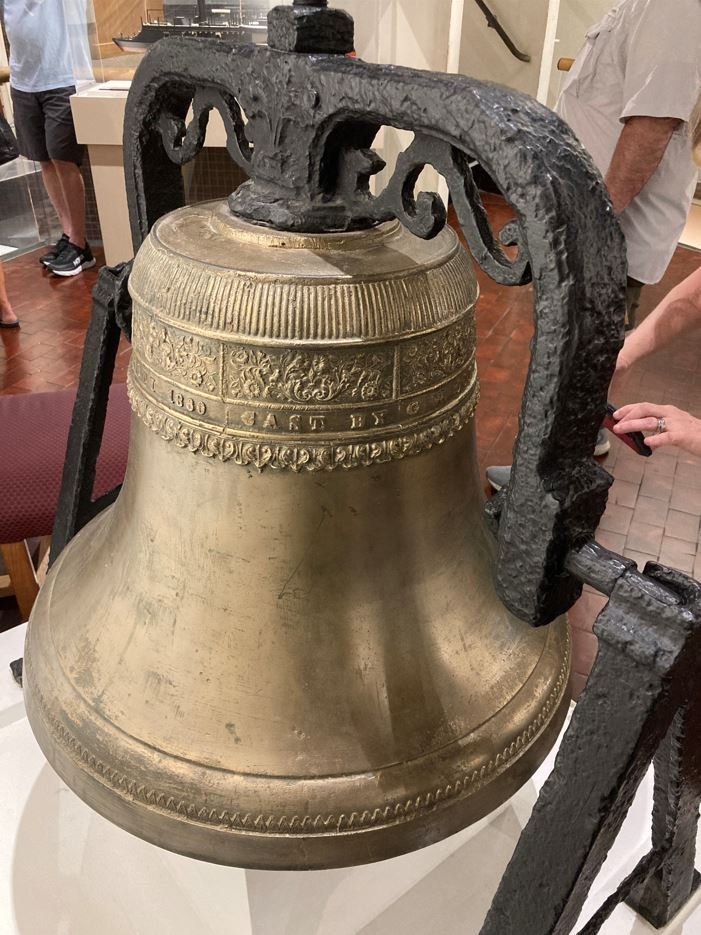
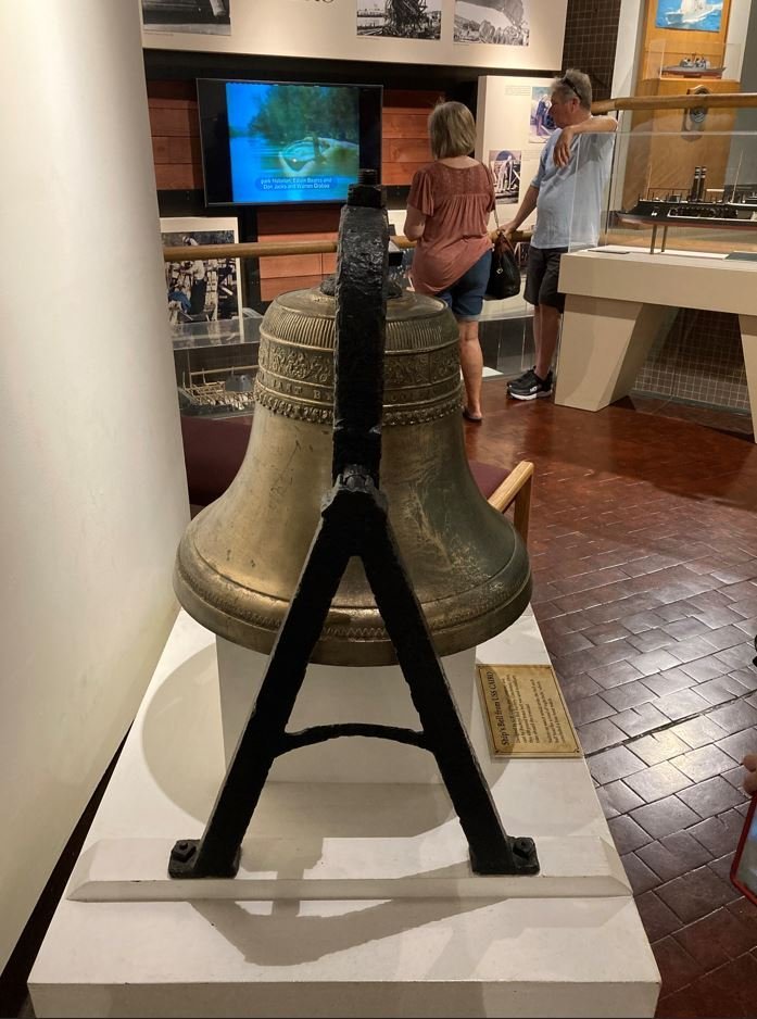
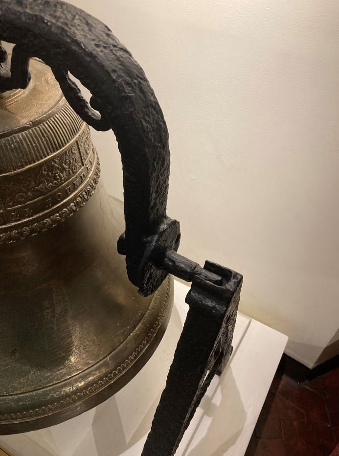
Johnhoward (Part 2), I was able to get pictures inside the museum as well. For your viewing pleasure. Ships Bell. I took these from all angles so that I can get my representation correct. One of the cool stories of the bell is that when it was discovered during the salvage, an air bubble trapped in it from 1862 was released and travelled to the surface. Original cannon carriage with a fiberglass mock up of a burst barrel. Deck Howitzer from the USS Pittsburgh. The Cairo's Howitzer was removed shortly before Cdr. Selfridge took command, so it was not on board at the time of its sinking. Many of the artifacts on display in the museum. One of the copper clad lanterns used in the powder magazine. Original wood fabric and display model. Cutaway model. Cairo's Bilge pump. One of my favorites. This painting hangs behind the front desk of the museum. I am not sure of the artist, but what intrigued me was the frame was made from some of the original wood taken from the Cairo. -Brian

- 739 replies
-
- 15
-
-
-
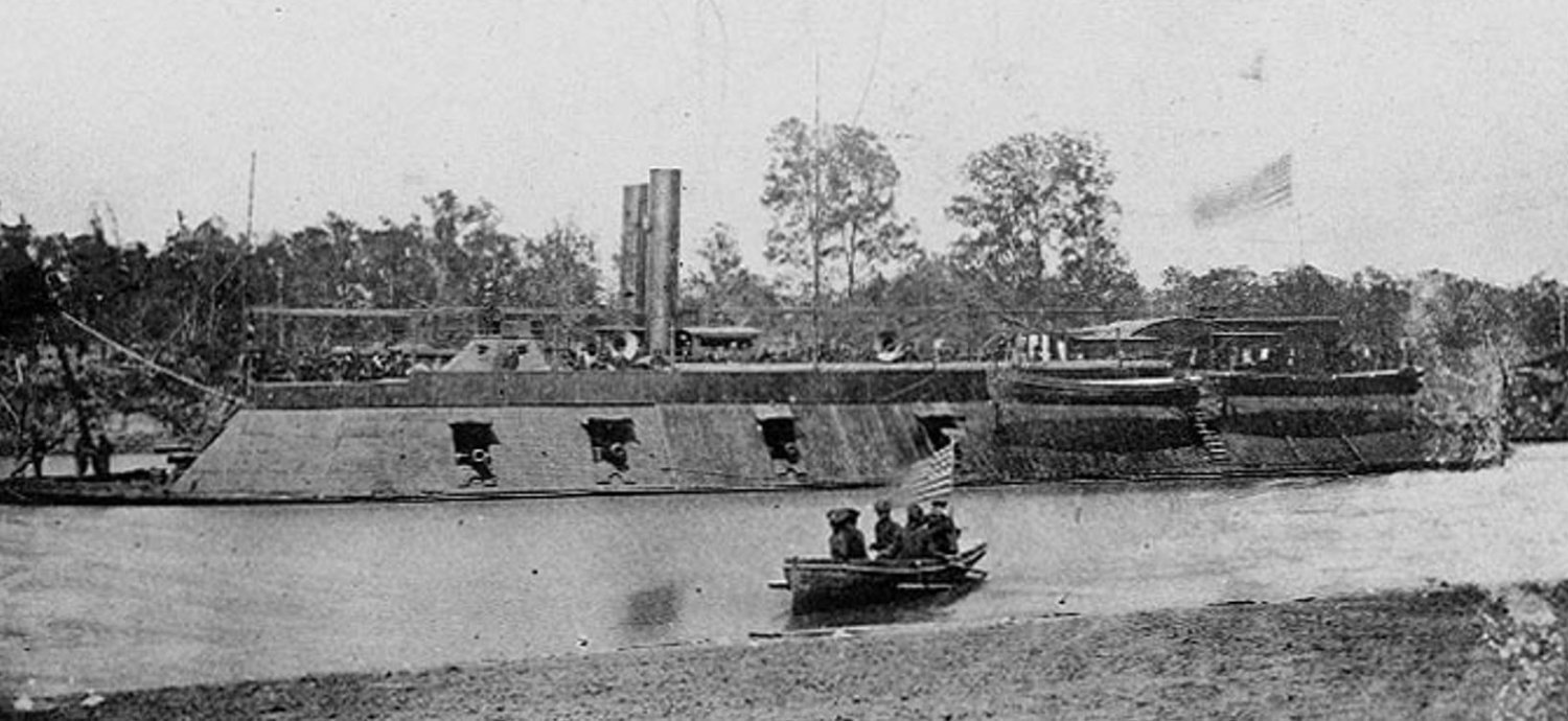
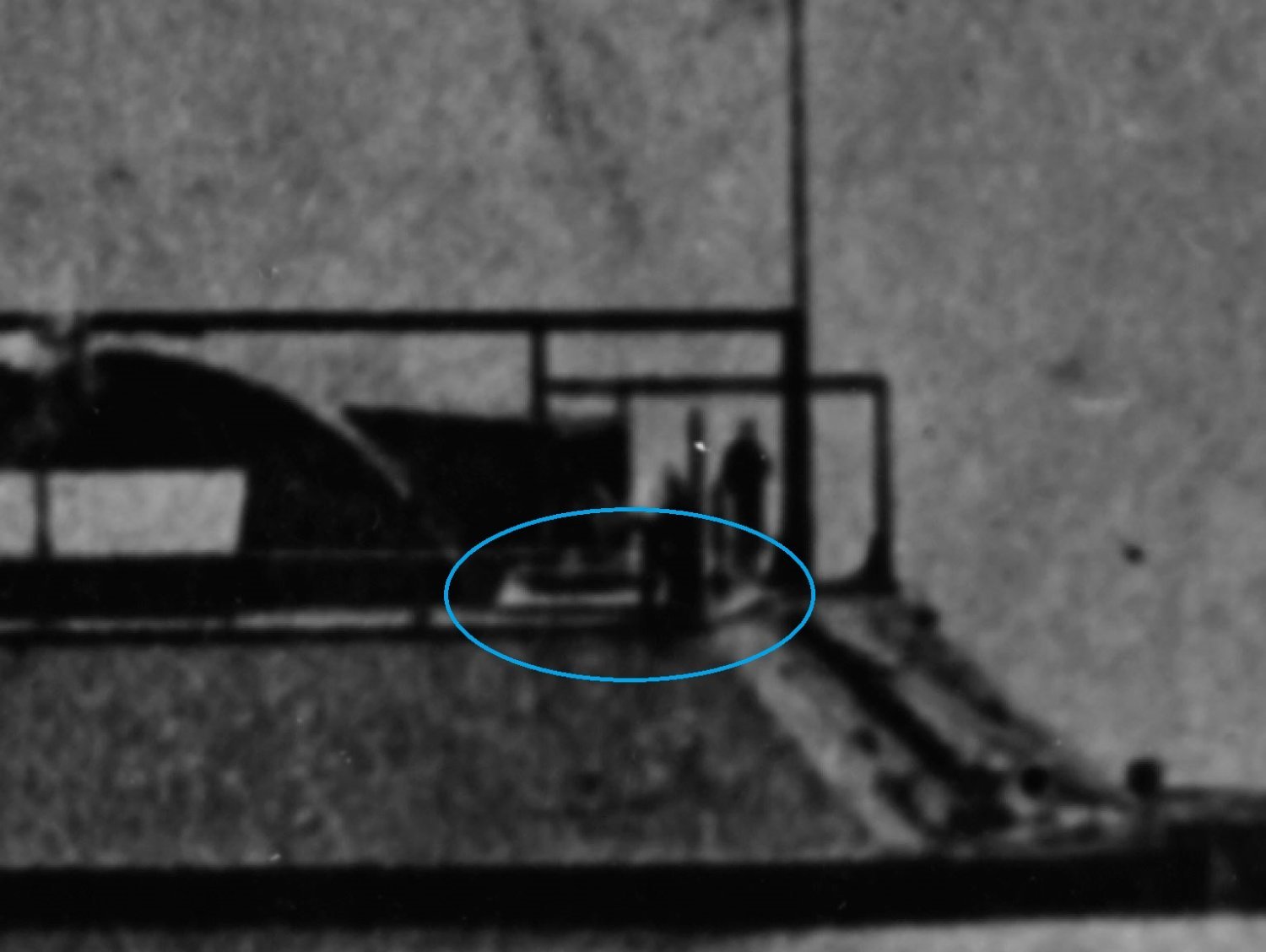
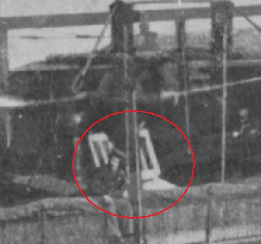
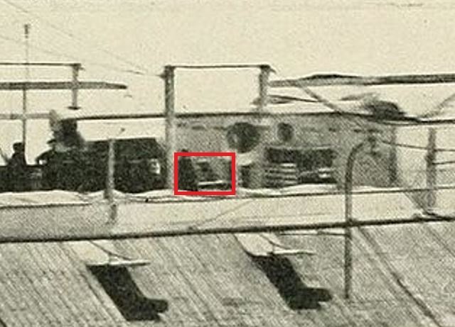
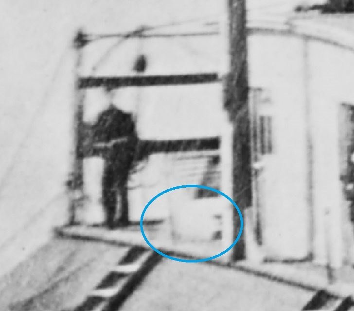
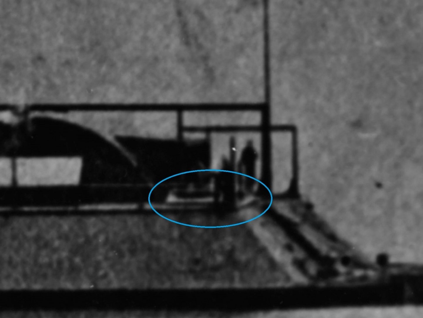
Johnhoward, how right you are. I am still having to pinch myself at how lucky I was to get to see the lesser seen parts of the museum and boat. A once in a lifetime trip I would have to say. I am going to have to say that there was indeed a skylight located between the hog chain posts, at least on the Cairo. I have not been able to determine this section on any of the other photos of her sister ships, but I just may not have found the right picture yet. Looking at the picture below, it is clear that there is access way down to the gundeck located in this position. This is one of the topics that Ray Hamel and I discussed at length, and he agreed. If you look closely, you can see that the hatchway door itself is constructed just like the forward skylight with long slender windows and the interior is whitewashed like the forward skylight as well. As for the positioning of the funnel, I struggled for a long time on this one trying to determine if the funnel was located inboard or outboard of the hog chain posts. I have played around with several angles of my model to get the view just right and have come up with their location being just forward of where Doug Ashley has them on the HSR plans. In this position, there is still room for them to rotate 360 degrees without any interference. I would not think that they were removed and stored in this picture, they look to be the same height as the rest of the photos that have them in position. There is one picture of the Mound City that has the forward funnels removed and stood up on deck and they are significantly taller when removed. However, these were over the fire room and may have been longer given that there was no gun deck directly below them. This is just my observation though. For the aft skylights, there are several pictures of these. The photos below are snippits from the St. Louis, Carondelet and Cincinnati all showing skylights located above the aft cannons. You can also just make out this skylight out on one of the pictures of the Mound City. Being that the Cairo, Cincinnati and Mound City were all constructed together at Mound City, IL, my assumption is they would have been built pretty much the same way. St. Louis: Carondelet: Cincinnati: Mound City: Given all of this research, I feel pretty confident that these are skylights and would have been located here on the Cairo as well. These would have provided several places to assist with the loading and unloading of supplies. They are somewhat located above the gun deck hold hatchways that are shown on the HSR plans, and they would have provided mores egress points in the case of the ships going down. Having these skylights/hatchways could also account for all 175 crew members making it safely off the Cairo in just under 12 minutes. -Brian


-
Roger, another good example, albeit not ship related, is the Centralia, PA coal fire that has been burning underground since the early 1960's, and could possibly burn for 100's of years more. As for the gunboats, if I remember correctly, the powder was stored as far from the boilers as possible in the aft pontoons on either side of the waterway. The holds were lead lined and they had special copper clad lanterns to help with lighting, but prevent any accidental discharge of the powder. The coal bunkers were located in the hold, forward and to the port and starboard sides of the boilers fire boxes, I believe these were open to the fire room so they could have possibly vented any gasses though the funnels and skylight located above the boilers. Not too much remains of this structure, so it's hard to tell if there were any other ventilation methods used, but given the design of these boats, all of the coal would have been stored under the floor of the enclosed gun deck. All munitions were stored in the forward holds under the exposed foredeck. -Brian
-
Thank you Ken. I pretty much said thank you to him so many times that he may have gotten tired of hearing it. Interesting factoid, you have here. To be honest, I have never given too much thought to how coal was processed. I have seen hundreds of coal cars on trains and piles of it outside the power plants (in south Louisiana as a kid), but up until just last year I had actually never physically touched a chunk of coal. The admiral and I were at Cumberland Falls in Kentucky walking around, and I picked up what I though was a black rock, but it was extremely light for its size. Come to find out it was pieces of cola that had washed downstream and settled on the flats just above the falls. As for coaling the boilers, the Cairo was documented to burn up to a Ton of coal an hour when underway, so I can see why the stokers were fit, shovel work will make a man out of you real quick. -Brian
-
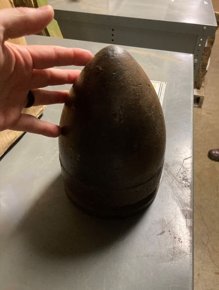
Mark, these memories will definitely last a lifetime. I am right there with you. With so many people out there trying to to erase certain parts of our history (apologies if that sounded political) it would be a shame if this piece suffered that fate. It's is a beautiful exhibit, one that every one should see. Keith, love what you did there with the pun. 😁 I still have a hard time believing my luck or fate, whichever way you want to look at it. I just look back and think that I wasn't even going to go back into the museum to see if Ray was there on the second day or not, and to run into him as we were leaving. It was just meant to be. The funny thing is that the day before, I was telling my wife, as we were standing at the stern of the ship, how much I would love to get down there and take some up close pictures. The pieces are a true treasure. They will go along nicely with the Adm. Selfridge signature that you guided me to, to go along with my display. I just need to figure out how I am going to fit it all in and show it properly. Snug Harbor Johnny, That is some very interesting information. I had not heard of the Hunley being made from a converted boiler tube, but it does make sense. The Hunley was definitely cramped for space. Not sure if that would be on my list for a scratch build. I have several projects in the works once my Cairo is completed. But you neve know, it would be an interesting build. Eric, I was more than happy to share my experience, especially with those that can truly appreciate it. I know what you mean about placing a face to a person. I took over a new group with my company back in September last year. We are a 100% work remote group and I have yet to see what anyone on my team looks like. I like knowing what the person on the other end of the line looks like. Most of us on MSW know each other by what our hands look like, since that is usually all we get to see of them. 😁 I miss following your builds, hopefully you can recover soon and get back to building. Pat, My pleasure. I do hope that they are able to do something soon to help protect it. I found an old picture that I had taken on my first visit to the Cairo, shortly after the exhibit opened in 1984. I did a side by side stare and compare to a picture I took this weekend. Over the past 38 years, there has been a noticeable change in the original fabric, especially on the more exposed areas. Although they did try and prolong the decay by building the new "Tent" structure that you see today, it still needs to be in a controlled environment to prevent any further damage. Roger, Thank you. I am sure I made his day. My wife said that he was just as excited to talk about the boat as was seeing it. The great thing about it was that all I asked him for was to look at his models. Everything after that, he offered up without me asking. The only request that I asked him for was to take pictures and handle some of the artifacts. The tour was all his generosity. And after working at the Cairo for over 15 years, he was well knowledgeable on all aspects of the boat. He even agreed with a lot of the errors that I was able to find through research with the HSR and current display, like the skylights/hatchways and hammock nets. Thank you for the kind words and following along Brian. As I mentioned to Roger above, I was just wanting to discuss some of my questions that I had about my build to make sure that I was getting the details as accurate as possible. I hadn't even give a thought to asking if I could get a VIP tour. I guess it wasn't something that I thought that they did. Thankfully Ray offered it up, I was not about to refuse that offer. The grapeshot stand is about 10' tall and weighed about 75lbs (it was surprisingly heavy). From what I could tell was most likely used in the 8" Dahlgren, since it was a smoothbore cannon. I am not up too much on the ordinance (yet) but that is my best guess right now. The 42lb projectiles were about 14" long and about 7" in diameter and probably weighed in the neighborhood of 75lbs as well. -Brian
- 739 replies
-
- 11
-
-

-
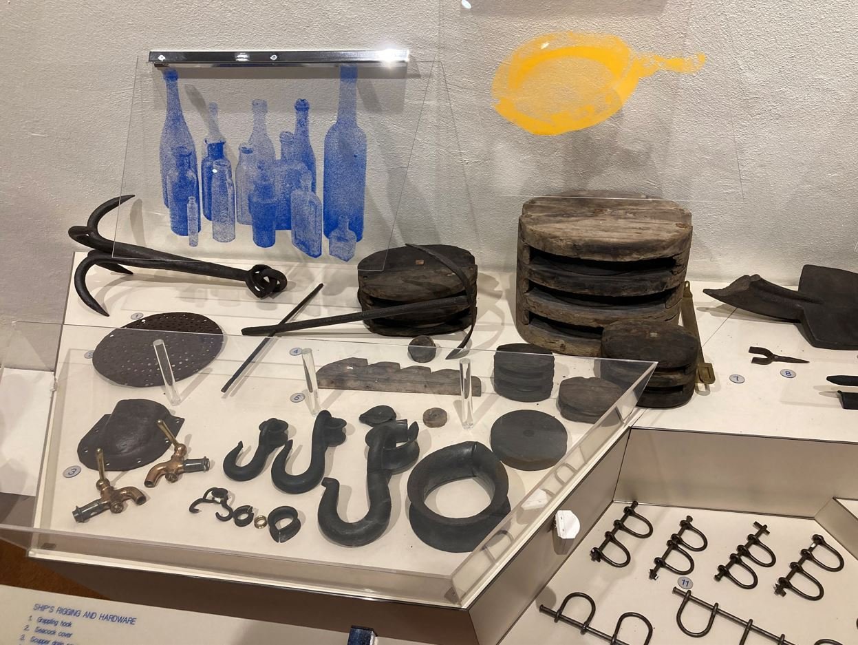
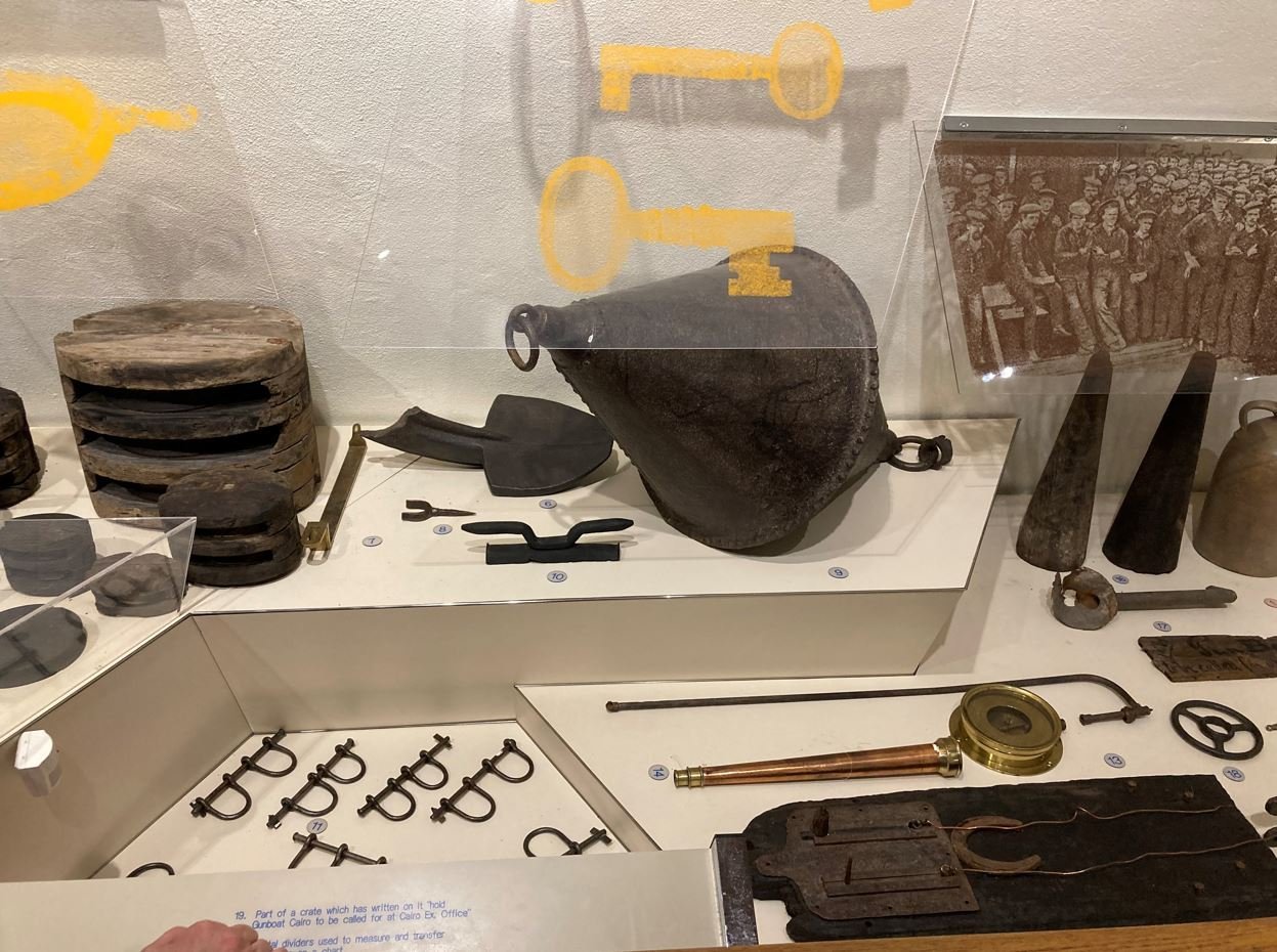
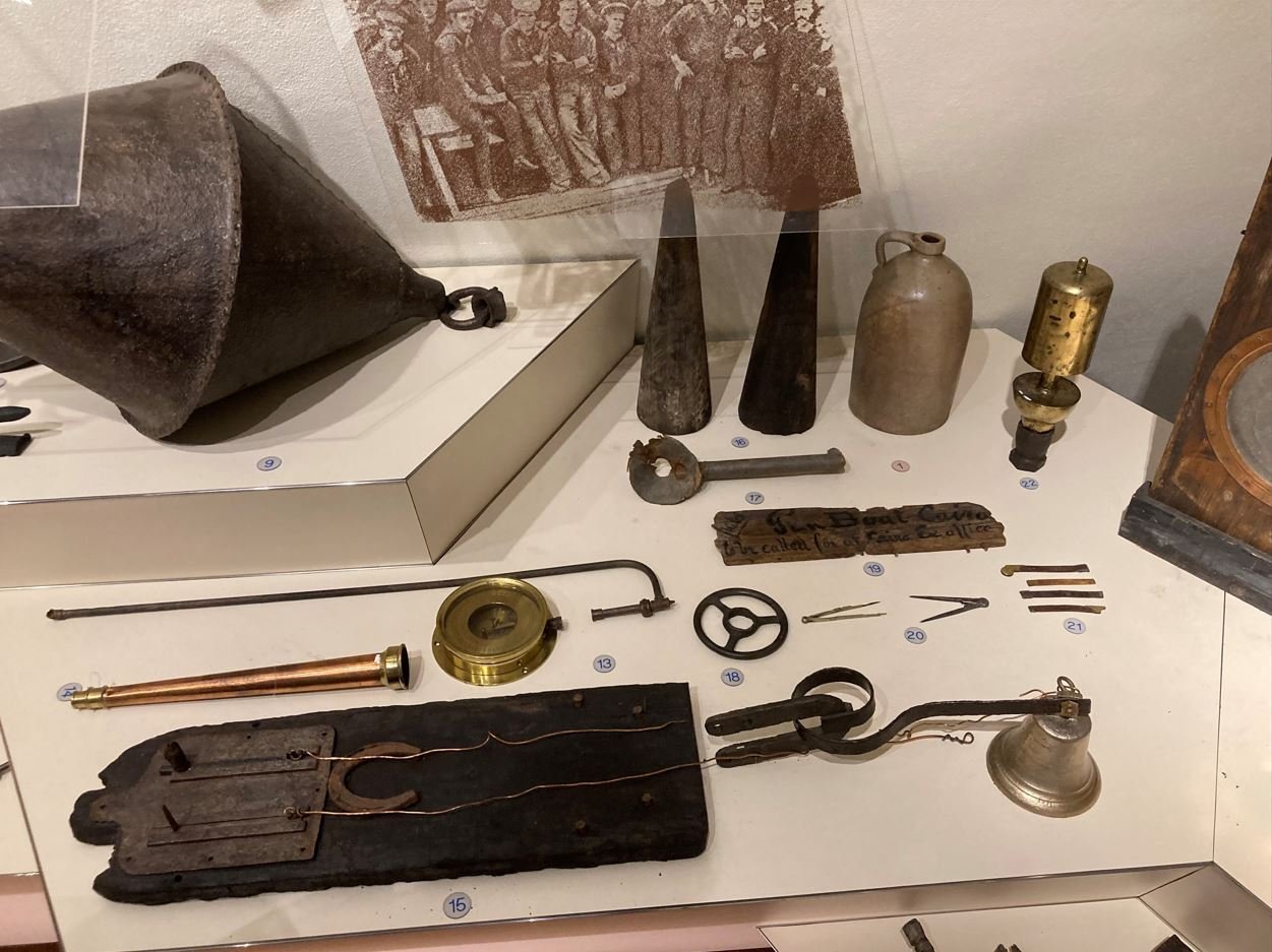
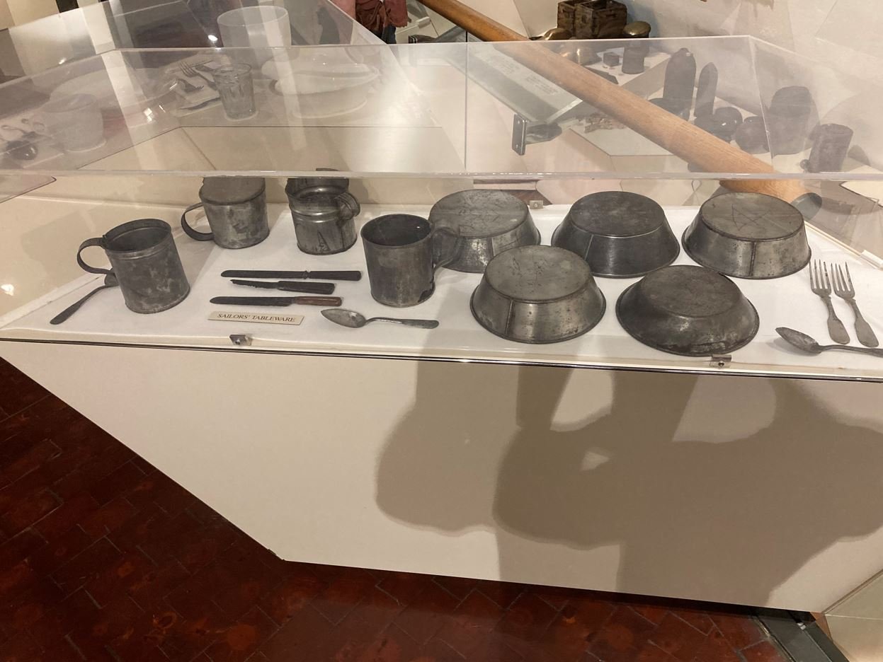
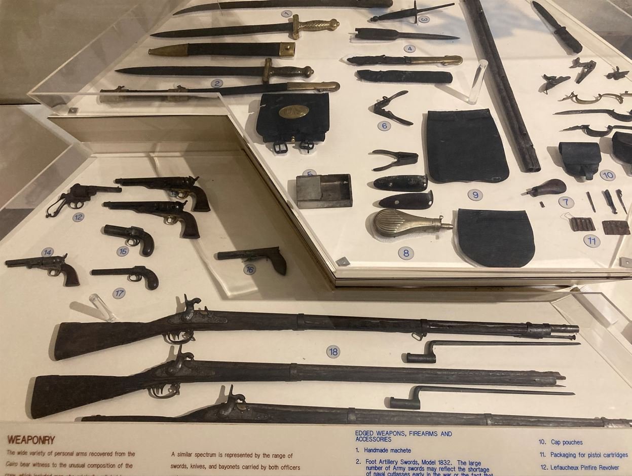
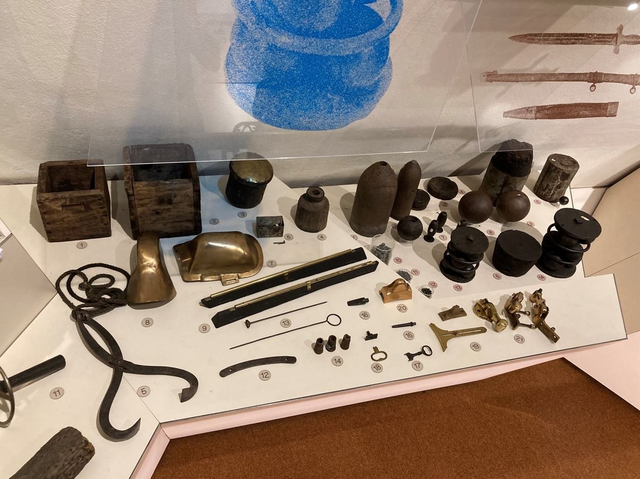
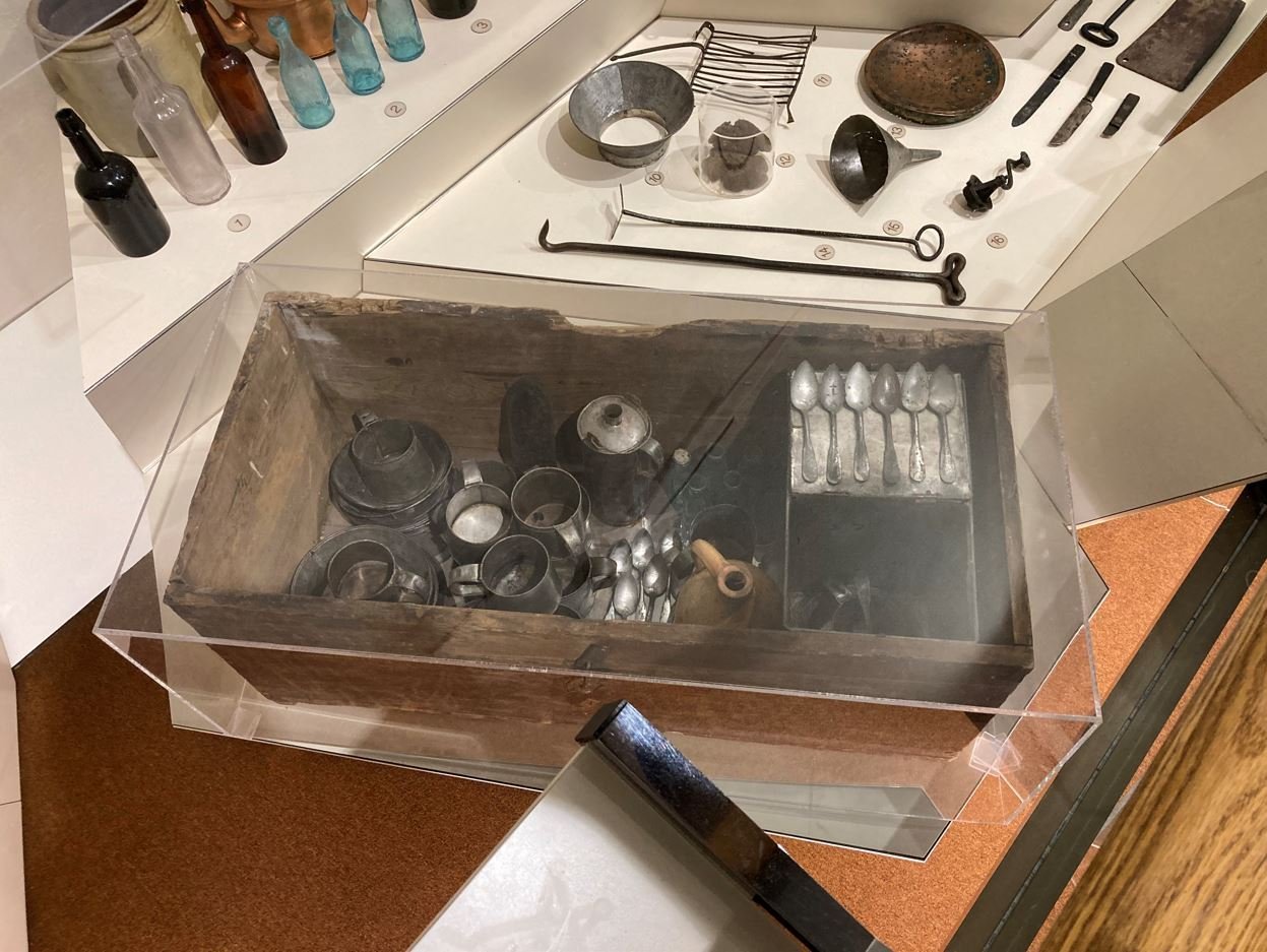
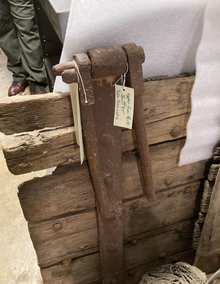
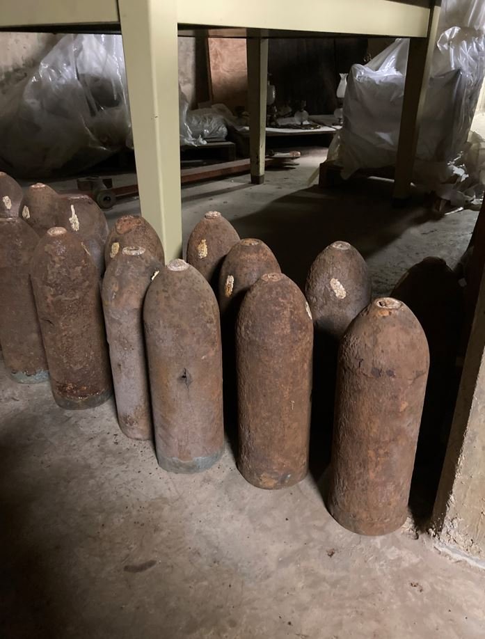
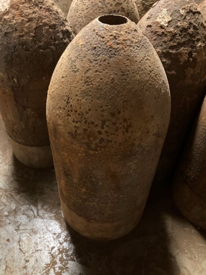
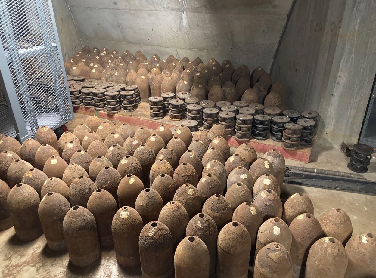
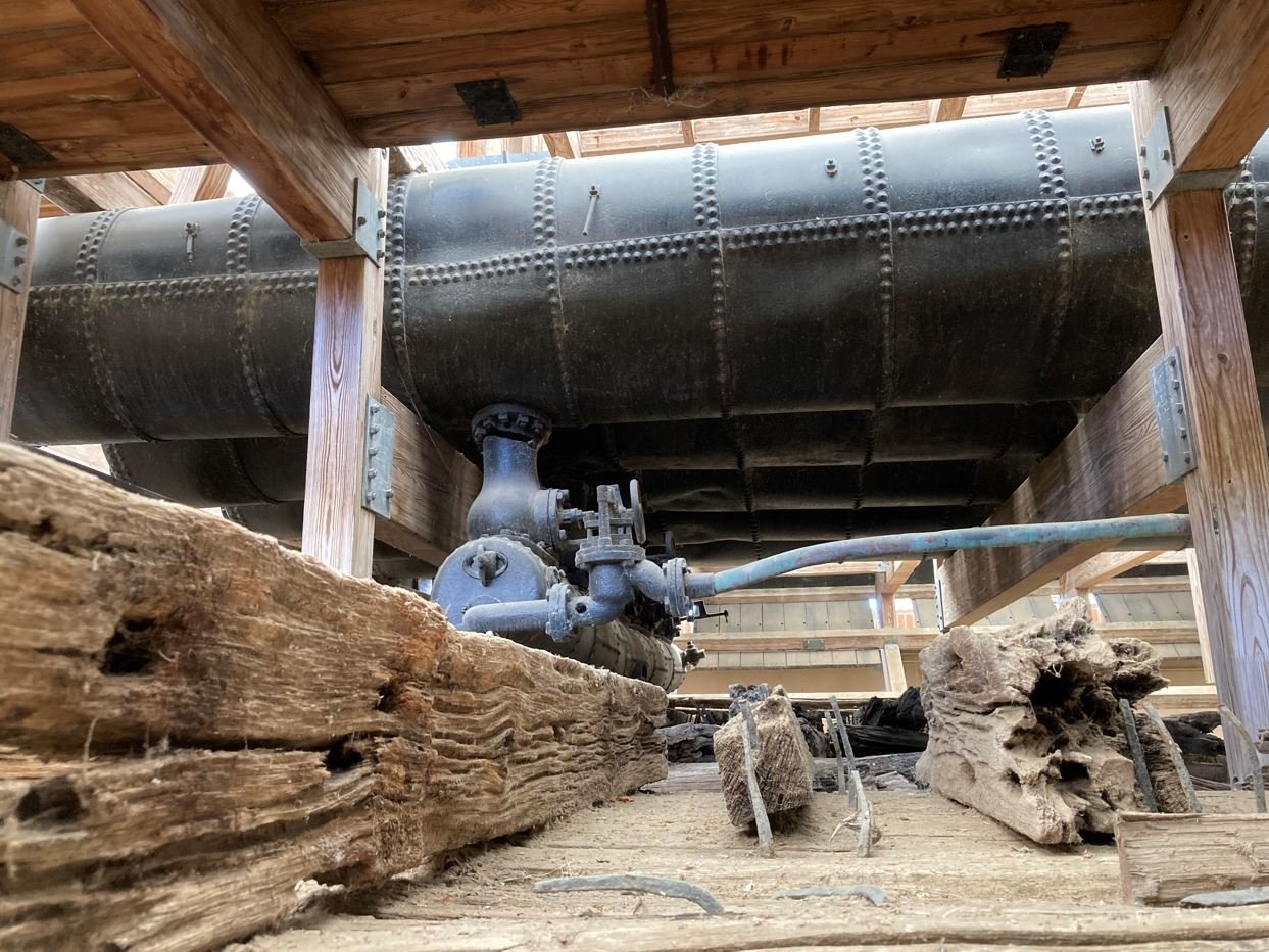
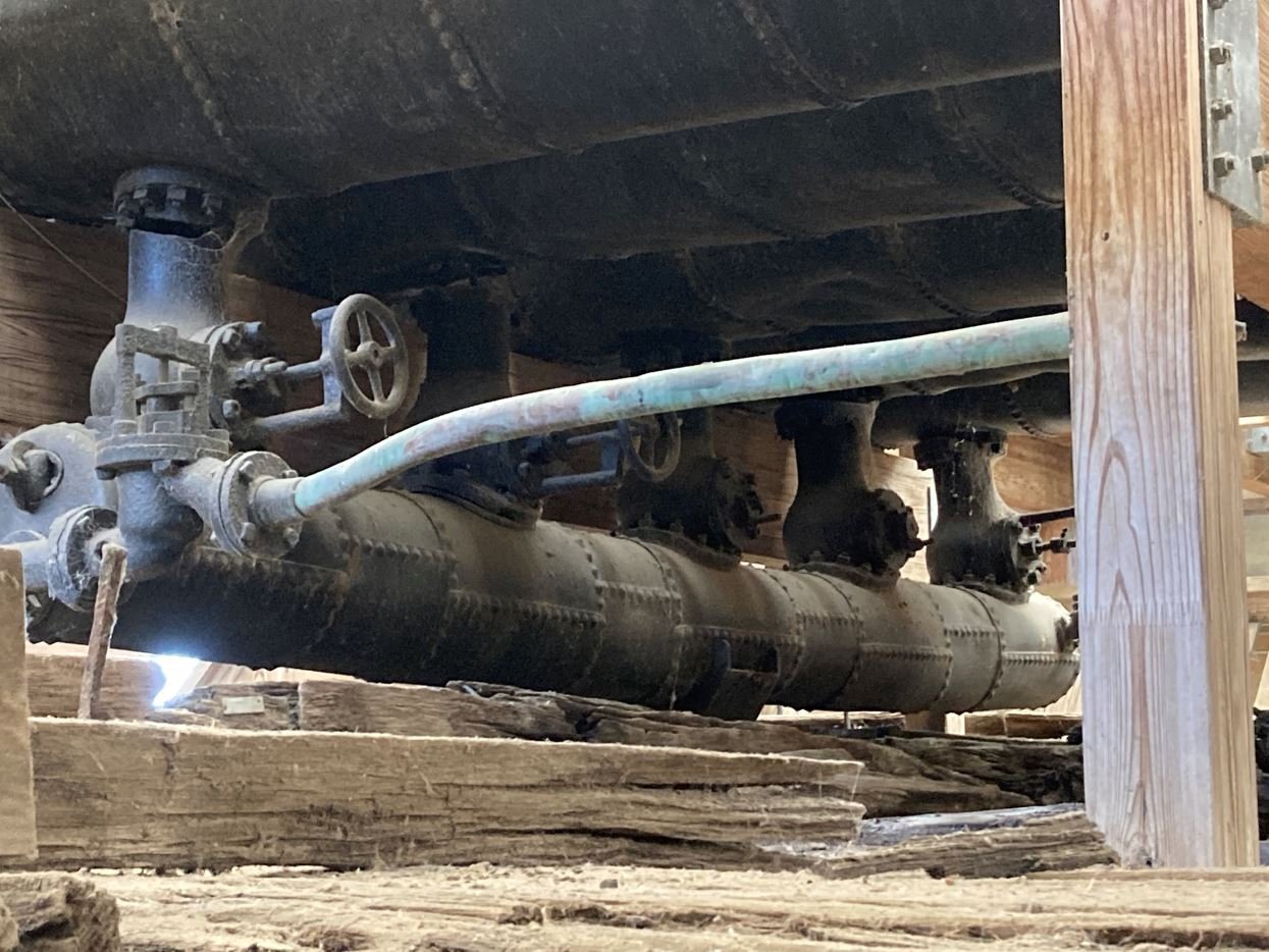
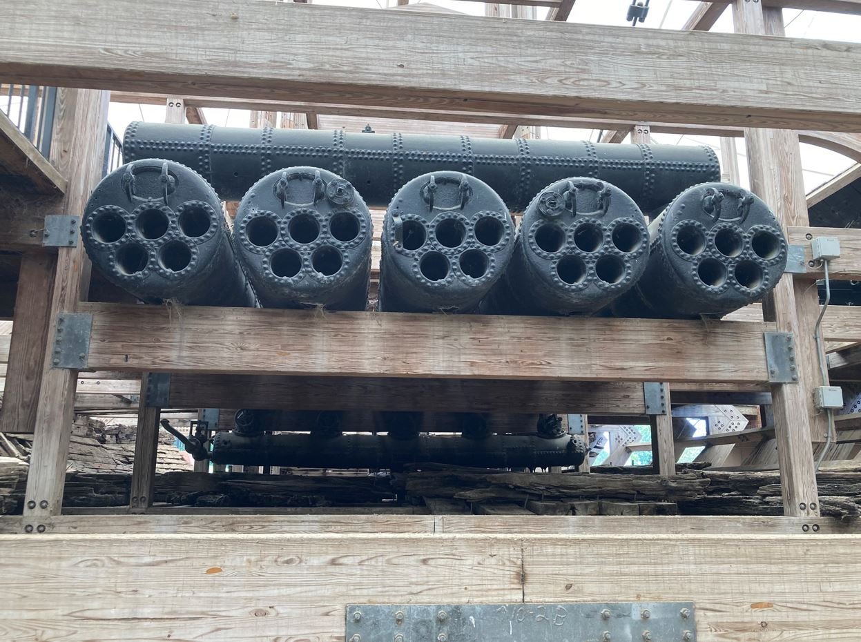
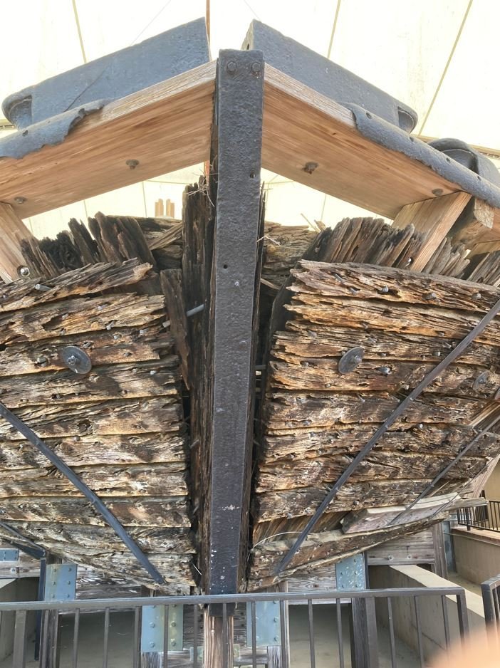
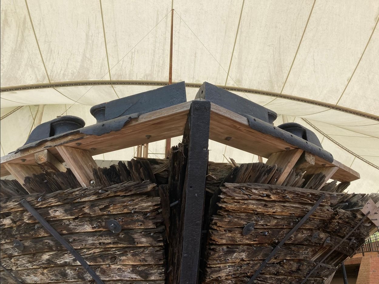
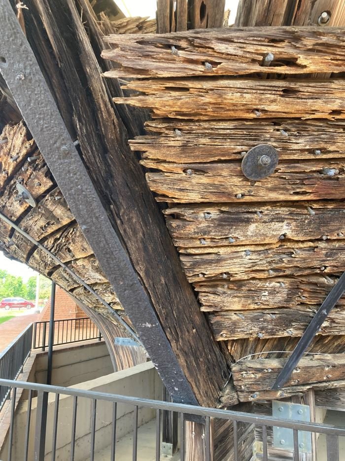
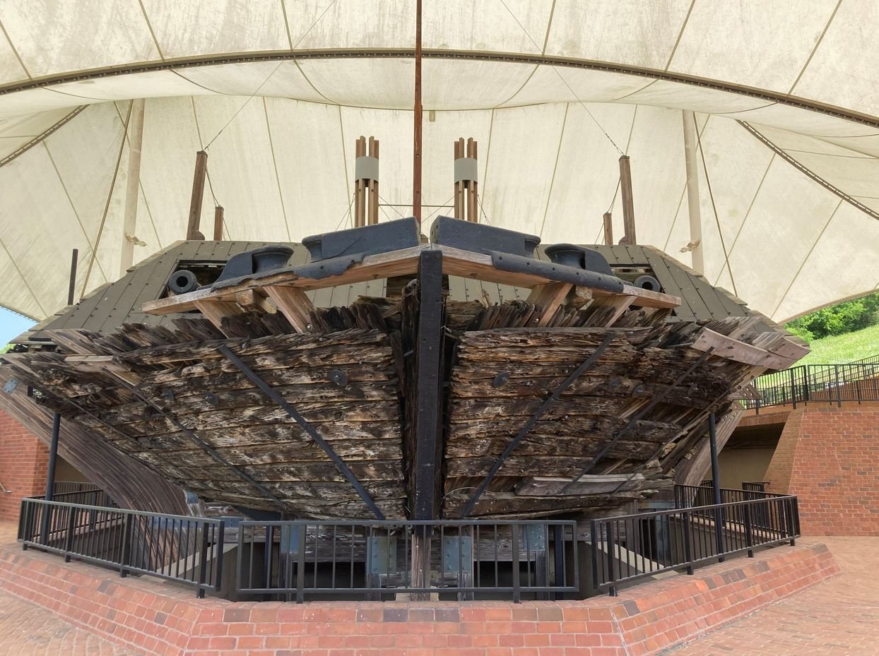
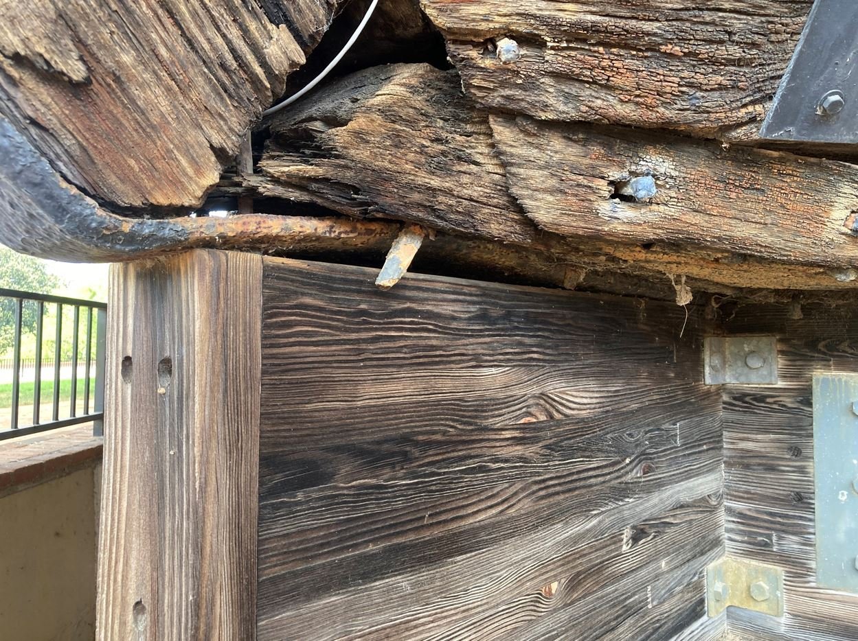
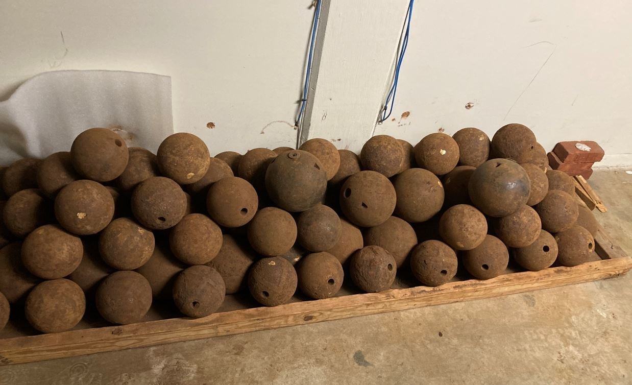
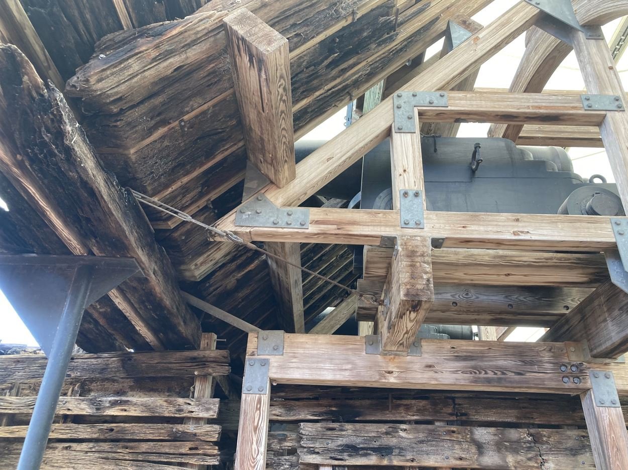
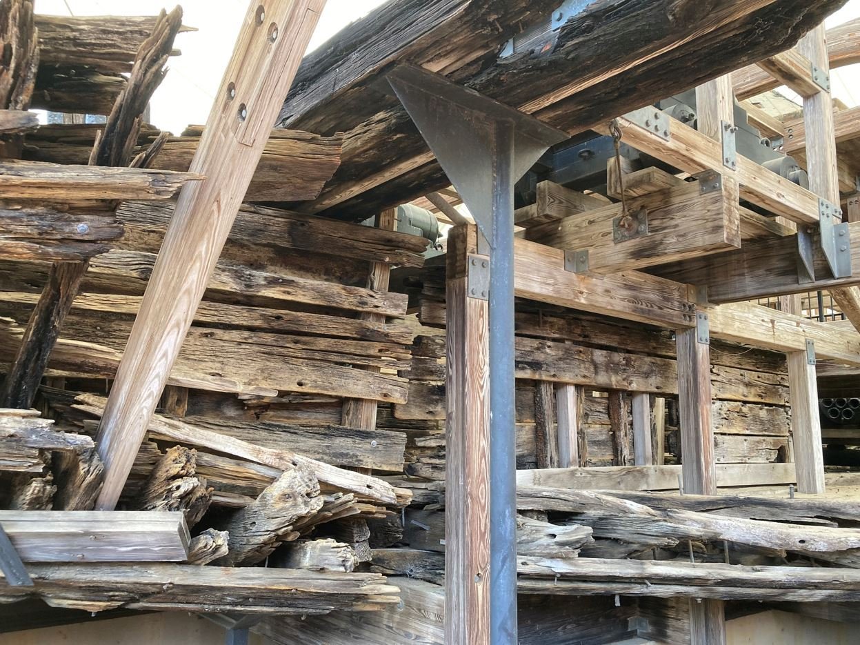
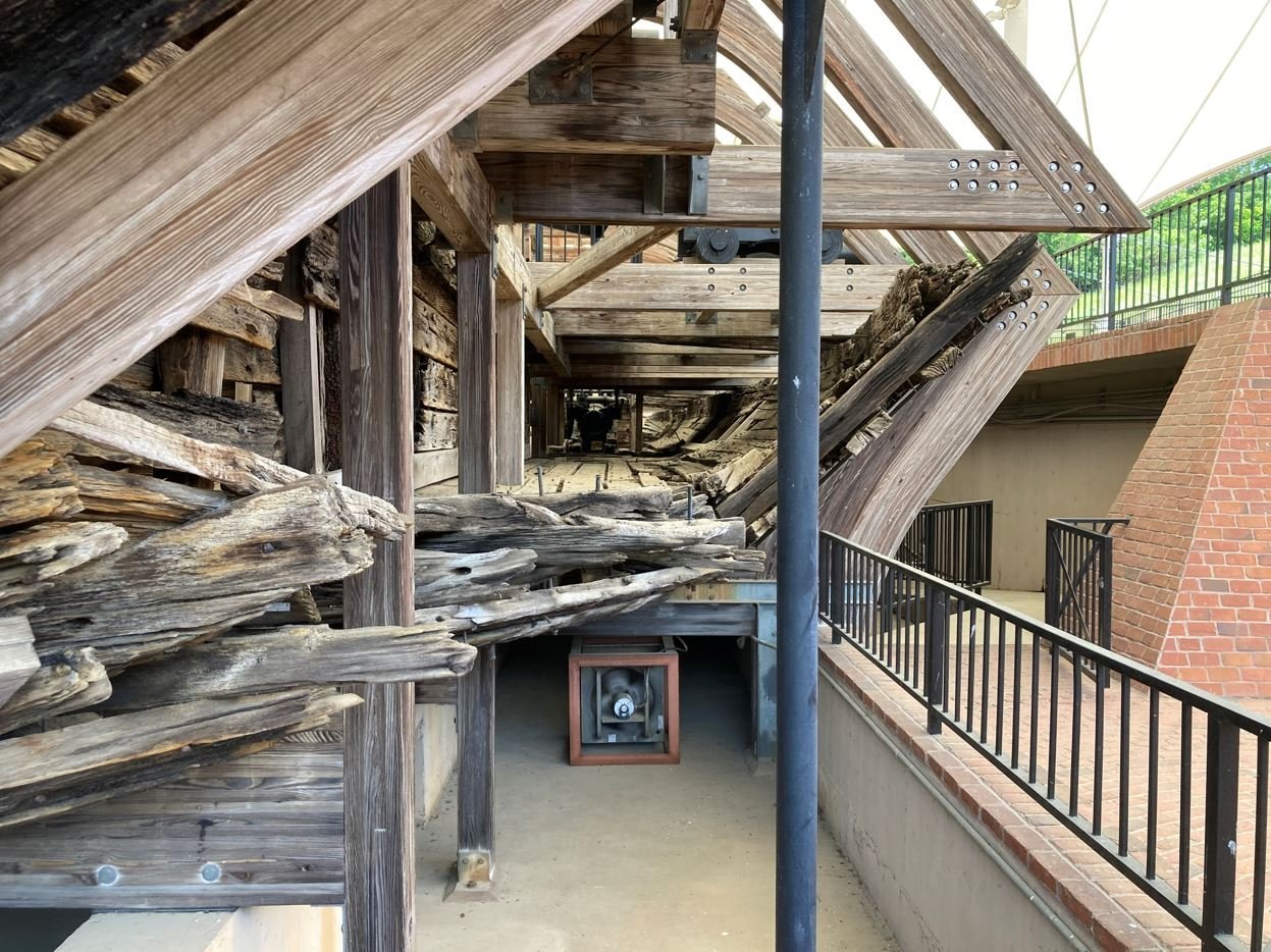
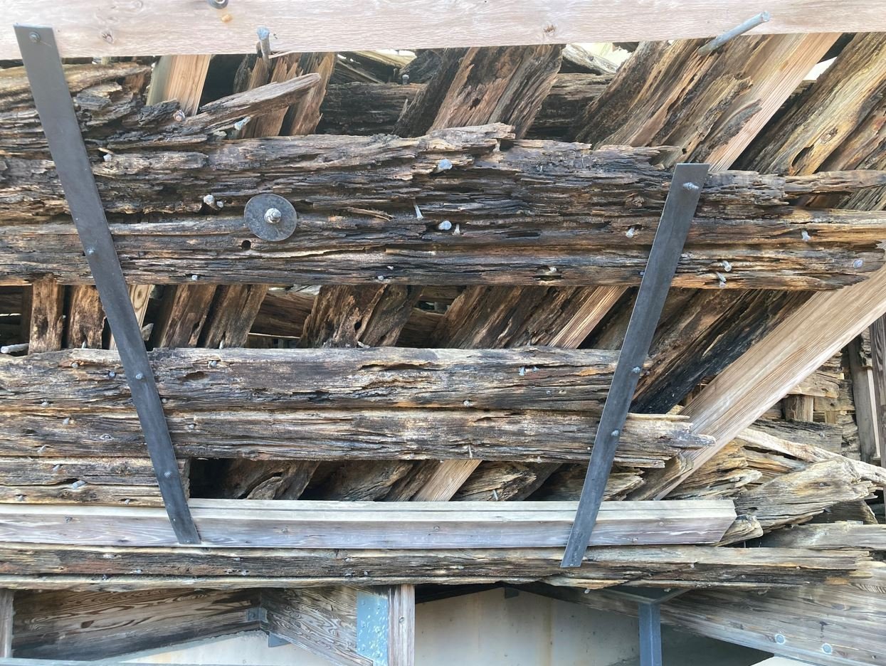
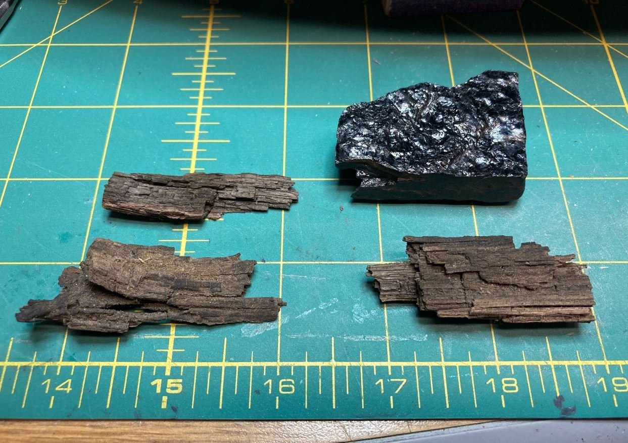
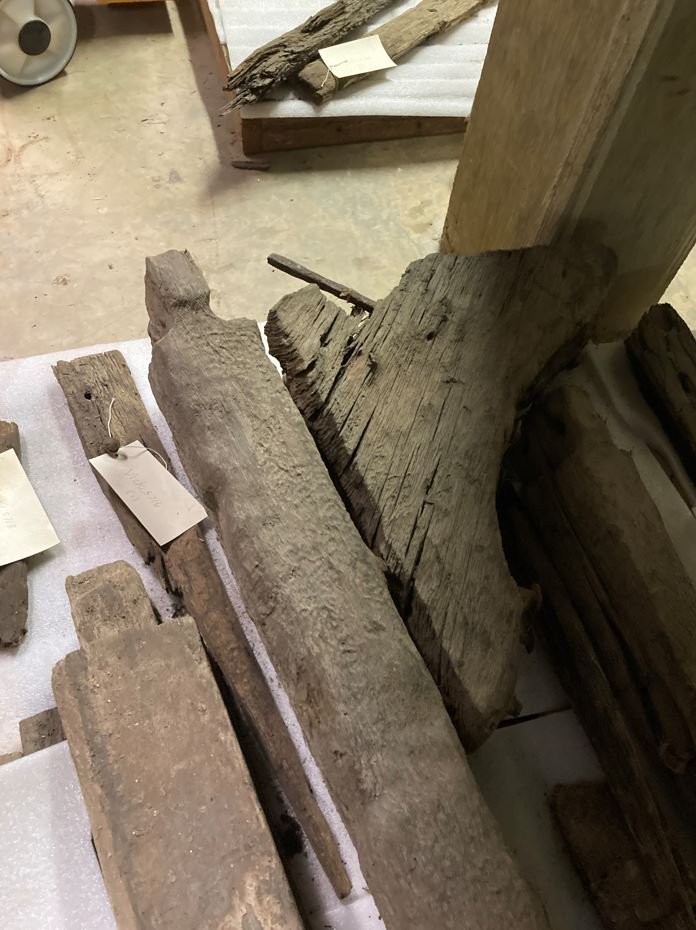
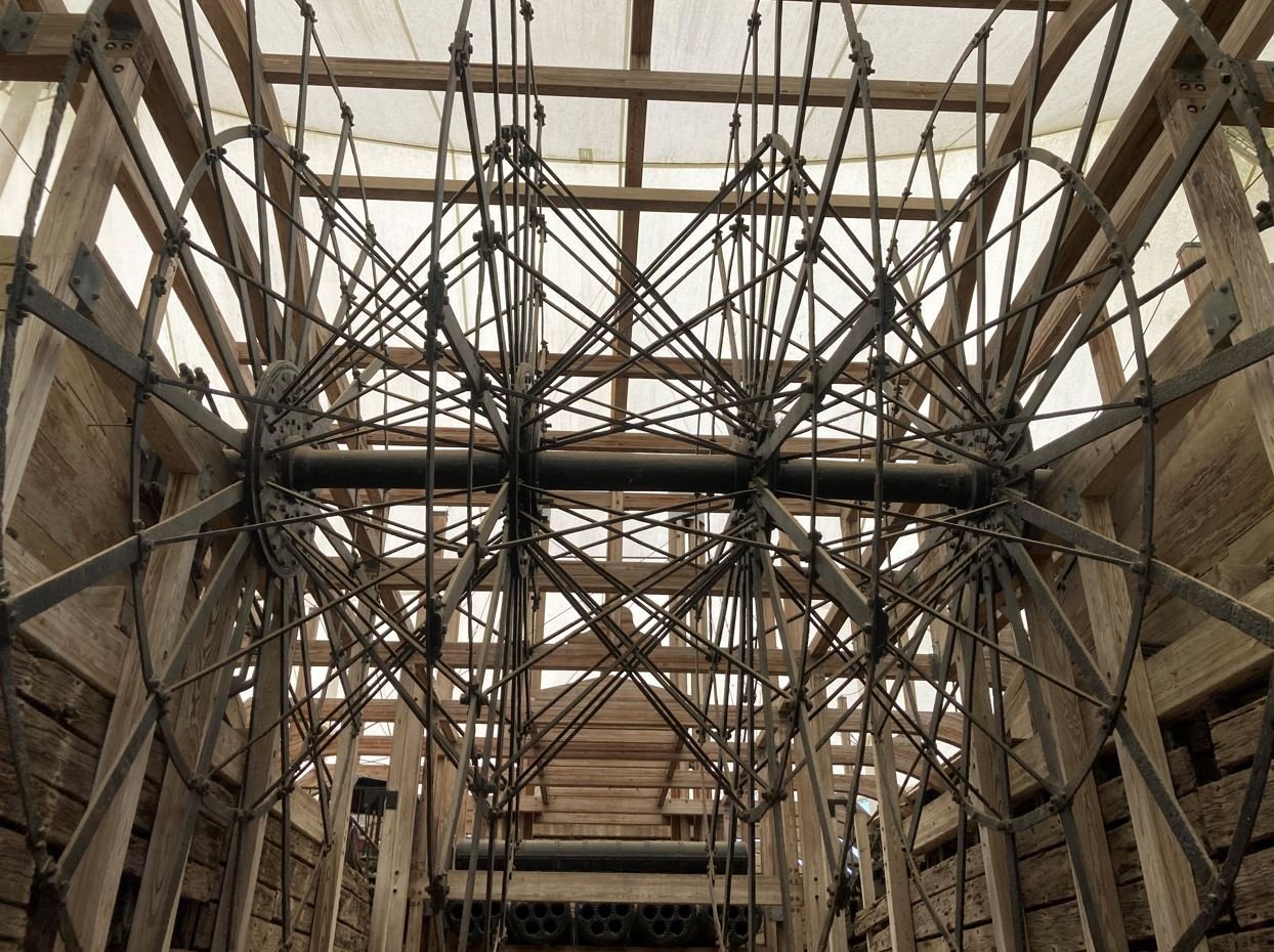
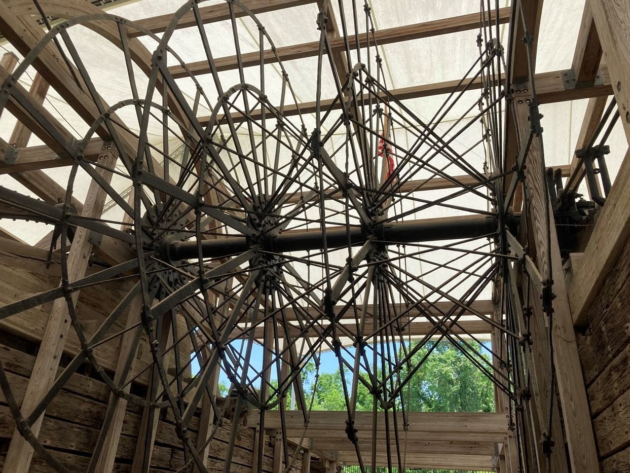
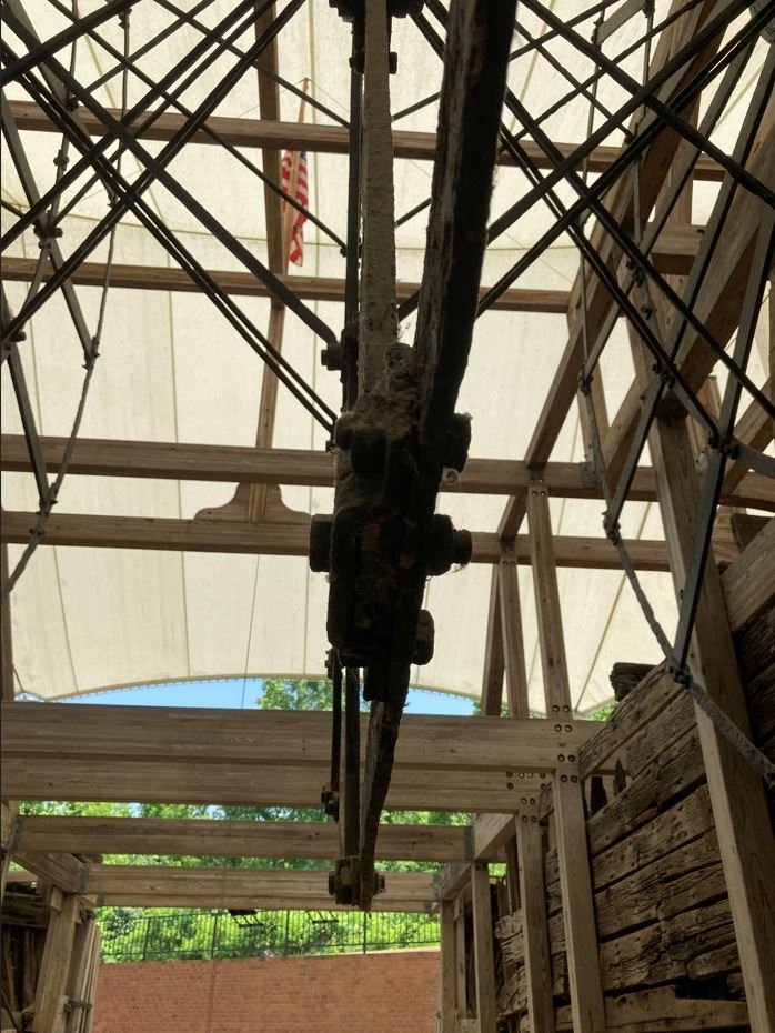
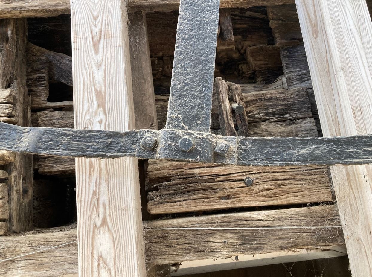
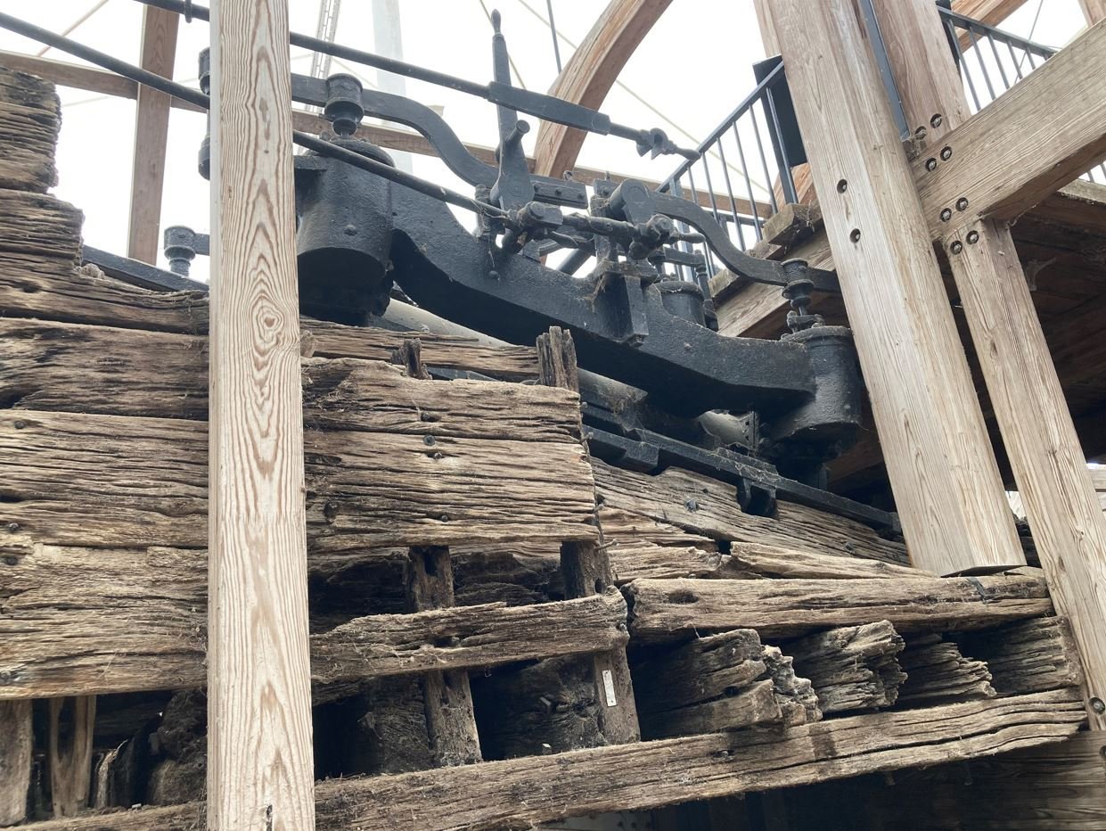
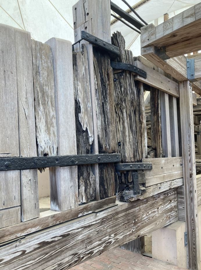
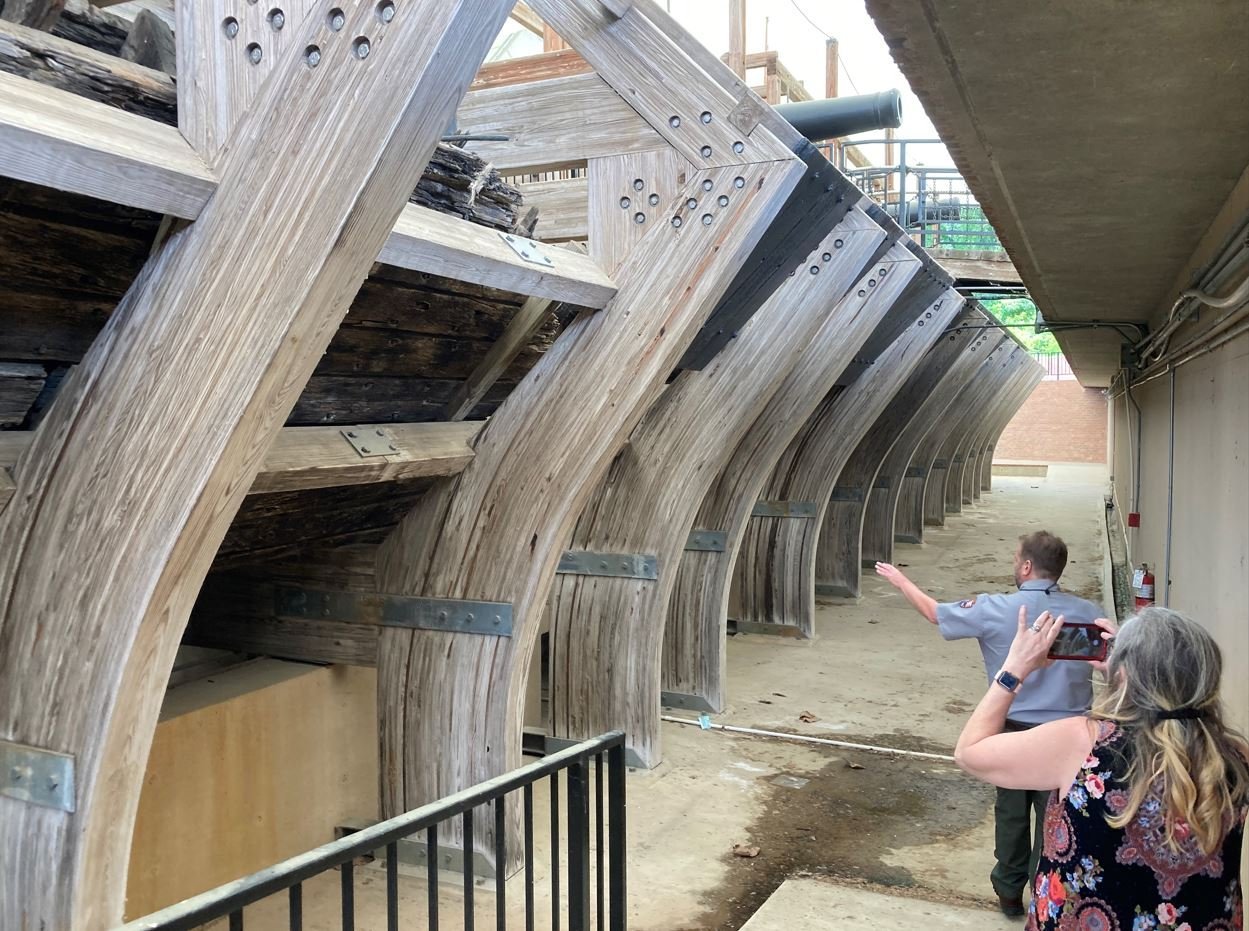
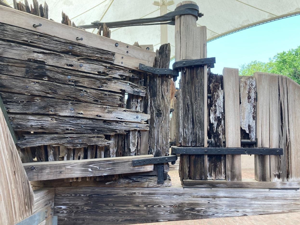
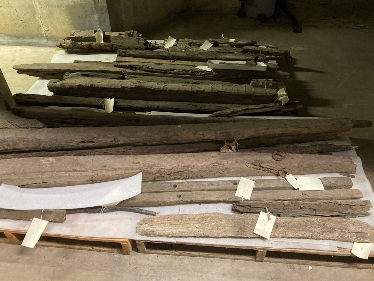
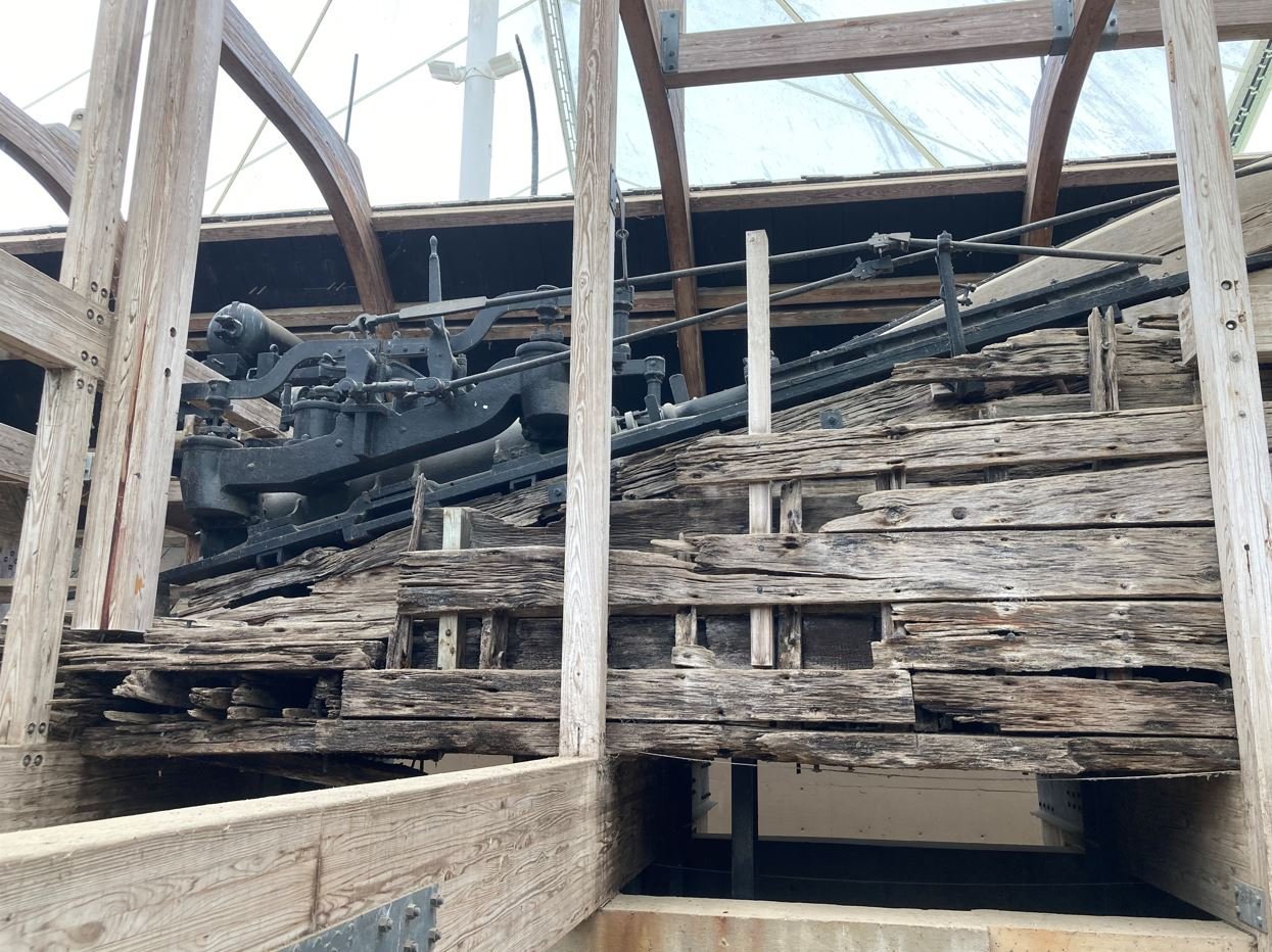
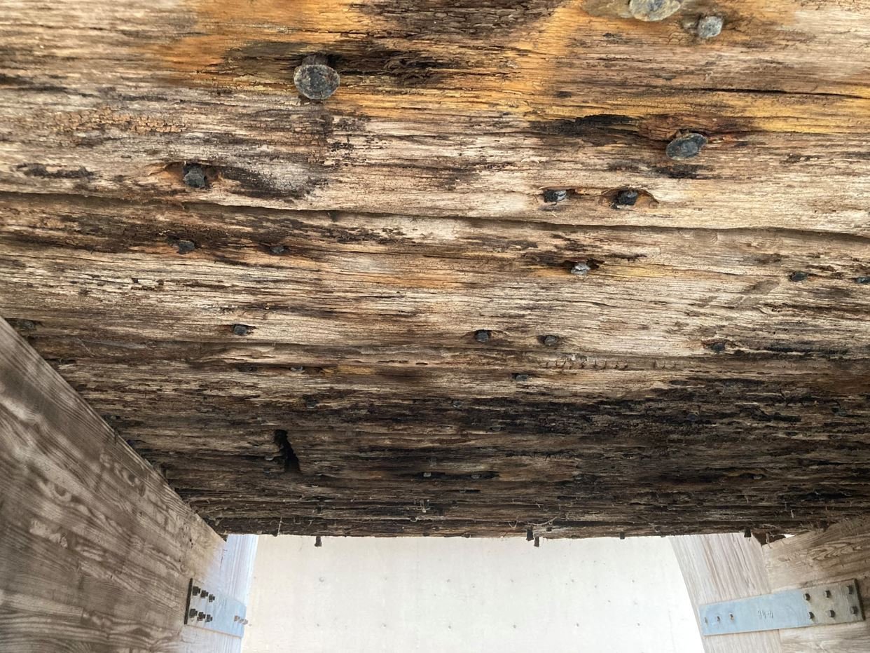
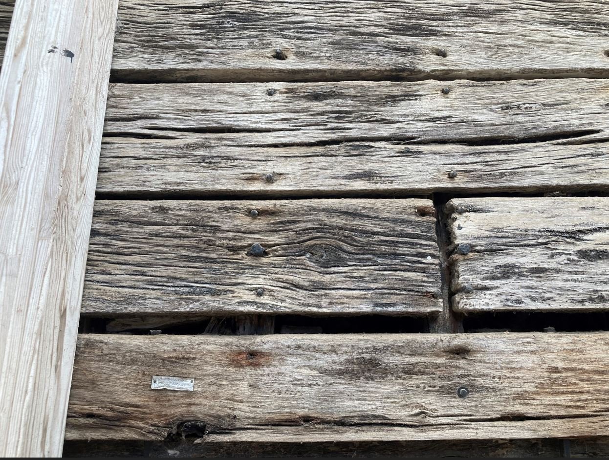
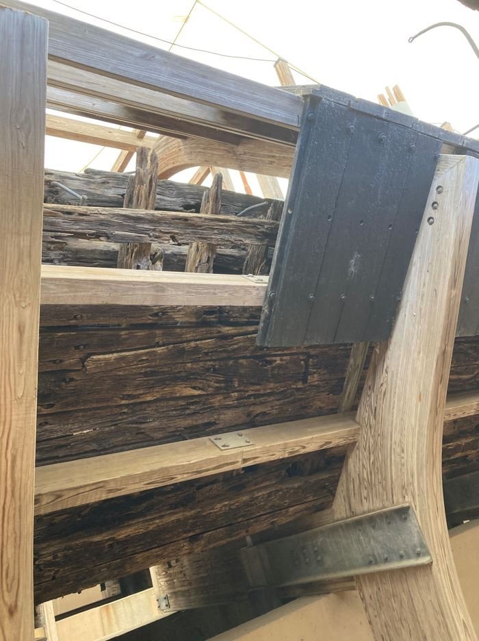
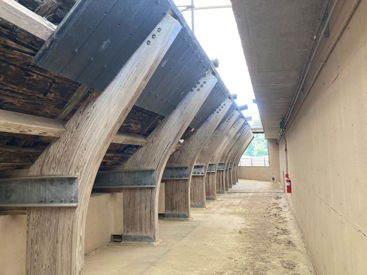
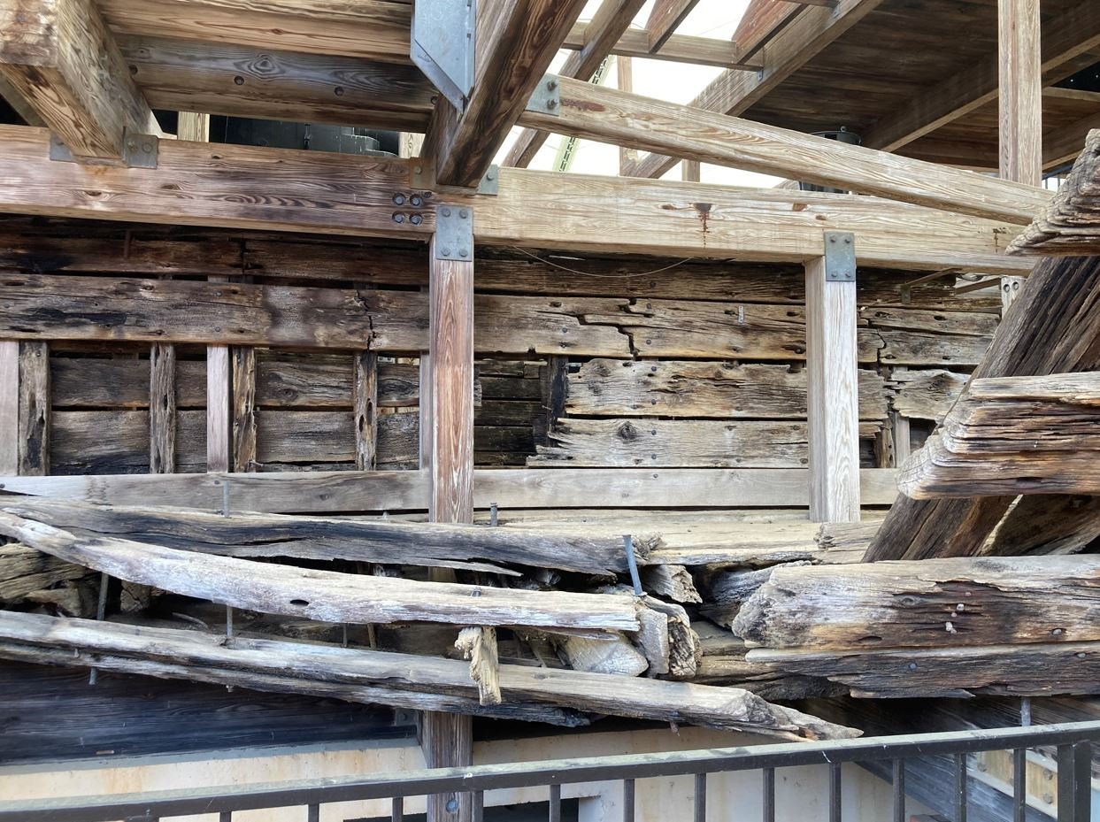
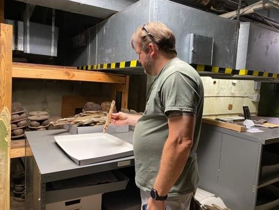
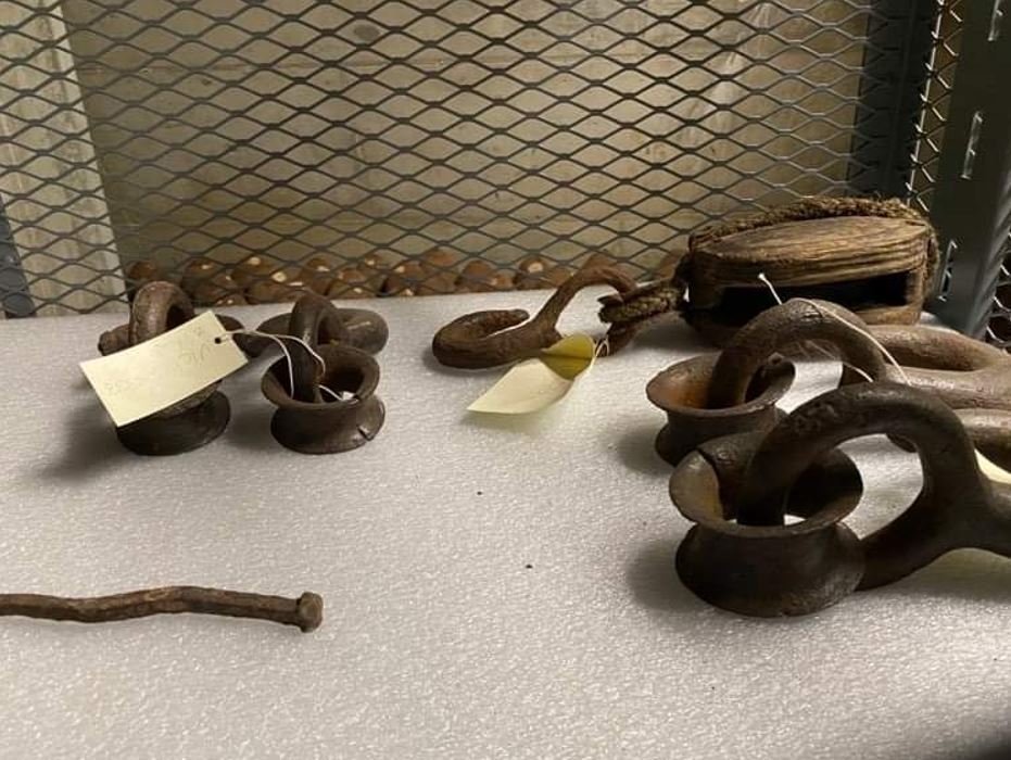
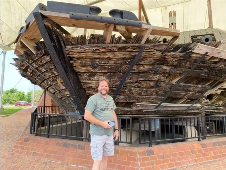
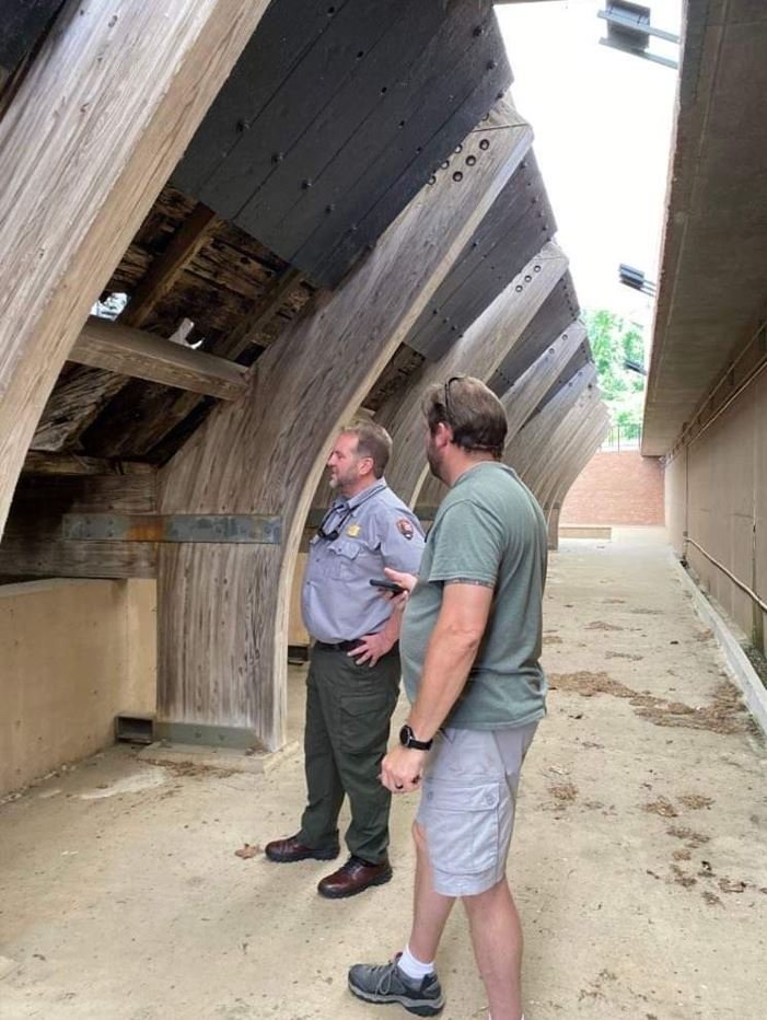
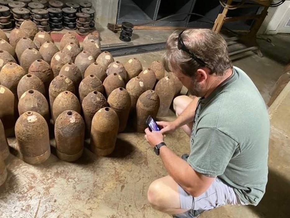
Hello again Everyone, I don't have an update ready yet, but I do want to share a few pictures from my recent trip to Vicksburg NMP. The admiral and I wanted to get away for the weekend, so on the spur of the moment we decided to go to Vicksburg. She didn't care where we went, as long as it was away. So, since I was needing more reference pictures for my build, I suggested Vicksburg and she agreed. Lucky me. The first day we spent the morning driving through the battlefield, looking at the monuments and taking in nature. By noon we had reached Cairo museum and I started snapping pictures. While we were touring the museum I got to talking to the Ranger at the desk about the boat and my build. I showed him some pictures that I had on my phone and then introduced him to my build log. He seemed genuinely fascinated by it and asked if he could show it to the powers that be. Of course I told him by all means. So while we were talking, I had noticed a couple of models on a shelf in the office behind the desk. I inquired about them and he said that they belonged to the Site Supervisor for the Cairo Museum, but he was off today and that he couldn't let me go back there to look at them. I understood, I wouldn't want some stranger wandering around my office while I wasn't there either. So we talked a little more, I thanked him for his time and we left. That night in the hotel, I was going through my pictures and realized that there were a few shots that I forgot to get. So I sweet talked the admiral into stopping by for a few more pictures. She was fine with that, she wanted to tour the National Cemetery just across from the Cairo exhibit any way. The next day, I managed to get the shots that I needed and we moved over the cemetery. We walked around there for an hour and a half or so until it started to get hot. We were getting ready to leave, but needed a restroom break before getting under way. As we were literally walking out the door of the museum, we bumped into the Site Supervisor Ray Hamel. We started chatting and I asked him about the models in his office and he was more than happy to let me come back there and take a look at them. They ended up being the Cottage Industries USS Cairo & CSS Arkansas. We got to talking about my build and that we had come here to do a little more research on some areas that I was having problems with. That was when my day really got good. Ray then asked if we had some time to take a walk with him. Well of course I wasn't going to refuse, so we set out on what ended up as what I would call a VIP tour. We went down stairs from his office to the air handler/storage room. This is where they keep a few overflow items that didn't make it to the actual artifact storage facility. Once we got down stairs I was totally in heaven. You may recall that at one time the admiral said I looked happier than a toddler with a lollipop, well at this point I was even happier, like a toddler with a box of lollipops. In the storage room were hundreds of cannon balls and projectiles recovered from the wreck, Stacked all over the floor. There were also other artifacts such as a box of coal, timbers from the hurricane deck and other odds and ends. I asked to take pictures, which he said I could and not to push my luck, but asked him if I could handle some of the artifacts. He allowed that as well. Some 8" & 32lb cannon balls. 32lb cannon ball. 42lb projectiles and Grape Shot Grape Shot 30lb Parrot Rifle projectiles A couple of different 42lb projectiles. Gun Port Doors Box of coal. From what Ray told me, the coal was loaded on board in big chunks like this and then broken up before being shoveled into the firebox. A few other artifacts Playing around with a few pine wood fabric pieces that survived. One of the knee braces still attached to one of the stanchions. More of the stanchions and pieces of the hammock rails After I was done perusing through the room of artifacts, Ray asked if I wanted to go see the boilers? Again this was an offer I just couldn't refuse. So we proceeded through the next tunnel in the room to the lower level of the outside display. Now I was happier than a toddler with a whole case of lollipops. Take a mental note of my left hand in this picture and file it away for a moment. I'll explain this in a bit, but let me tell you I was buzzing with excitement. Ray was kind enough to let me explore the entire boat and take as many pictures as I wanted. Boilers & Mud Drum Paddlewheel Port Engine Starboard Engine Port Rudder Starboard lower armor plating. Starboard hull bottom. Waterway wall, Starboard side. These boards were in relatively good shape compared to some of the others. This area was buried in the mud for the longest period of time. Torpedo damage and bow area. The bow area. One thing that I missed on my build that I am going to have to go back and make is the bow reinforcement plate. I will have to go back and look at the documentation, but I don't recall any mention of it. Either way it is there and I will get it added. This plate was used to protect the stem timbers from shoreline rocks as well as taking out any makeshift bridges that were built across the rivers these boats were patrolling. I can't believe that I missed this part. I was trying to get a look at how far back the bow plate goes, but the supports cover most of it, making it impossible to see. I do know that it goes back at least 10' or so along the center keel from what I can tell. I was ordered by the admiral to post at least one picture of my mug in front of the boat. Just because. What an exciting tour this was, and Ray was very informative. Some of the topics that we discussed we the slow decay of the original wood fabric and how the Polyethelene Glycol (PEG) that they use to treat and preserve the wood is doing a lot of harm to it as well. Unfortunately budget concerns have also limited the treatments, with the last one being in 2013, whereas before they were every four or five years. He also told me that he has submitted several proposals for an enclosed, environmentally controlled facility to house the boat in that will help protect it and make it last longer. He said a few years ago that he was close to having one proposal passed, but funding was pulled just before being pushed through. It's a shame that a rare, beautiful piece of history is slowly deteriorating and the government wont step in and help preserve it. There are only four ACW Iron Clads still in existence, Cairo being the most intact one. You'd think that it would be somewhat of a priority to help save it. Fortunately, there are a few groups out there doing what they can to help see that the ship doesn't completely fall apart, one of the being the Friends of Vicksburg group. Other topics that we discussed were the positioning of the skylights, and the fact that the original drawings from the 1981 HSR do not show that there were also skylights (hatchways) amid ship and at the aft of the Hurricane deck. This proves my theory and research that I was correct with the placement of my hatchways between the hog chain support posts and that the two on the back just above the aft guns are also there (these are visible on the old photos of the St. Louis, Carondelet, Cincinnati and Mound City, but more on that when I post an update). Also, he did confirm that the hammock nets on Cairo were indeed constructed of wood, no netting. Some of the remains were in an above picture, along with the stanchions. Great information to make sure that I get my build as true to the original as I can. So, once were were done with the tour, we went back to Ray's office where he wanted to give me a card and his cell number to give him a call if I had any other questions. As a second souvenir he gave me a piece of coal that was recovered from the boat. Oh, going back to the picture I said to take a note of. While we were talking, shortly before the admiral took that picture, We were discussing the slow deterioration of the wood. Ray looked down and saw that a small piece of the wood hull had fallen off the boat onto the ground. He picked it up and aske me if I wanted it, my first souvenir. So now I am happier than a toddler that owns a lollipop factory. And again, I didn't refuse his offer. That is what I am holding in my left hand. So now my new pride and joys are here: They may not be much, but to actually have a piece of the boat, just brings joy to my heart. I am currently looking into how to preserve the wood fragments from further deteriorating and I think I'm going to incorporate them and the coal nugget into the display. Anyway, hope you enjoyed my story and that I wasn't too long winded. I should have an update on the build in a few days. Thanks for stopping by. -Brian
- 739 replies
-
- 19
-
-
-
Keith, I’m with Tom and Mark. I see nothing at all wrong with your work. I even zoomed in on the pictures. Beautiful job as always. -Brian