mbp521
-
Posts
1,003 -
Joined
-
Last visited
Content Type
Profiles
Forums
Gallery
Events
Everything posted by mbp521
-
 It’s all about getting it done. It’s not really fudging if the look is the same. That’s actually the way that I did it after a couple of attempts to bend the thicker material. -Brian
- 158 replies
-
- 1
-

-
- chaperon
- Model Shipways
- (and 1 more)
-
Looking good John! I do agree that those stairs are a bit tricky, no matter how easy they may look. But as you said, they are still nothing compared to the round ones on the King of the Mississippi. Unless you just pour the paint on, you’ll be surprised as to how much of the individual planks show through adding that touch of realism. If I may throw a suggestion out there, if you don’t plan on permanently mounting the hull to the base until you are finished with the model, I’d leave the rudders off until the very end. They tend to snag on everything when moving it around. It will also help to get them aligned when you install the paddlewheel and get the clearance right. -Brian
- 158 replies
-
- 1
-
-
- chaperon
- Model Shipways
- (and 1 more)
-
I’ll echo Mark’s comments. Life always takes priority. I’m in the same boat (pun intended), lots of work around the property that needs to be done with the cooler weather, so shipbuilding takes a back seat. Whenever you get back to the bench, we’ll be here to cheer you on. -Brian
- 113 replies
-
- 3
-
-
- Cairo
- BlueJacket Shipcrafters
- (and 1 more)
-
Just catching up on your build. You are moving right along with this. I am a little curious though, do the kit instructions call for the third cannon on the aft casement? Contemporary photos and the recovered wreck have only two cannons mounted on the aft of the boat on the port and starboard sides (a 30# Parrot and 32# smooth bore respectively). In the center aft over the water way was the captains cabin. It looks as thought the kit came equipped with 14 cannons, which would be correct if it is to have the 12lb howitzer on the Hurricane deck. You nailed it. There are numerous photos of the Cairo's sister ships out there, many of them show the wheel house structure with the doors and windows in different areas, of course this could be due to modifications or repairs over time. However, according to the only photograph of the Cairo, this was where the doors and windows were located. -Brian
-
Eberhard, I have to go along with the previous comments from Keith, Druxey and Thomas. At that small of scale, unless you are using a magnifying glass and closely inspecting the hulls, its not noticeable at all. You have all my respect. With my big hands there is no way that I could even come close to the quality of workmanship you produce on such tiny boats. I would have just drawn the individual planks on and called it good. 😁 -Brian
-
Thank you Keith. In pouring over all of the contemporary photos of these boats, I found that the outside decks were really quite busy, with plenty of tripping hazards. Especially the fore deck and fantail. I would venture to say that more than one sailor ended up in the water due to not paying attention to all of the ropes laying about. I've been on many museum ships and noticed that things were always stored away and tidy. Not having served in the Navy, I'm not sure if this is the way things were all the time on active ships, especially during wartime. Given the nature of the military, I would assume so. But, due to the limited number of photographs of the City Class Ironclads, they all seem to have a certain bit of clutter on the exposed decks so it's hard to tell if they kept the same standards at the time. I appreciate the kind words. I was hoping to make the build log as interesting as possible. The American Civil War is a dark time in American history, four years of brother against brother fighting. Growing up in south Louisiana (Baton Rouge) I was surrounded by plenty of reminders of this dark time. As a kid I was somewhat jaded to the fact that the South should have won and was resentful of the North for having done so. However, as I got older (and grew a brain) and studied more on the history of what transpired during that time, I realized that the Union was fighting to keep this country together. History has shown over time that countries that fight for separation from themselves, doesn't always work out like planned. Thankfully the US was able to stay together. No telling what things could have been like if the end result was different. Thank you so much Johann. I still have a bit to go. I spent a few hours the other day creating a punch list of things that need to be finished. As it stands right now I have at least a couple of months worth of work to do. Lots of small details and touchup work. Also, with the weather finally starting to cool off here, more outside projects are taking priority which takes away from the build time. I am trying my hardest to get it done by December, but I'm not going to rush it. Either way, I will have small celebration on December 12 to commemorate the anniversary. -Brian
-
Beautiful work as always Johann! Glad to see you’ll be getting to spend more time at the bench. That means more eye candy for us. -Brian
-
That is a huge difference in the shape of the parts. I can now see why you were having trouble sorting out the lines. Glad to see that Blue Jacket was “Johnny on the Spot” with getting the error corrected. Nic and his crew are always a pleasure to deal with. -Brian
- 113 replies
-
- 4
-
-
- Cairo
- BlueJacket Shipcrafters
- (and 1 more)
-
Nice progress so far. I’m glad to see more Cairo builds starting up here on MSW. While Cairo’s career wasn’t all that memorable, her history is truly fascinating. I’ll be following along on your build with great interest. -Brian
-
What a beast! I knew this was a big build, but seeing it sitting on the Workmate just gives a better scale to it. Totally impressive! -Brian
-
Beautiful job on the rigging Tom. These cross sections are much easier to rig up than the full ship. Not near as many snag points. -Brian
-
So much detail in such a tiny space. I do love the technique for getting the form of the boats. I will definitely have to give that method a try in the future. -Brian
-
Thanks for posting these Tim. Looking forward to seeing more. -Brian
-
The stained deck looks great! The Puritan Pine stain brought out the color variances of the wood quite nicely. -Brian
- 158 replies
-
- 1
-
-
- chaperon
- Model Shipways
- (and 1 more)
-
I meant digitally. I sent them in a PM to you, let me know if you are able to open the file. I also have printed plans that I am pretty much done with if you would like them. They are a little marked up, but you are more than welcome to them if you want them. -Brian
- 113 replies
-
- 3
-
-
- Cairo
- BlueJacket Shipcrafters
- (and 1 more)
-
Eric, quite the conundrum. The top of the hull should align with the deck with no overlap or underlap. Where the casements meet with the hull on the sides at the knuckle should be a fine point where the armor plating goes and then a rub rail extends along the hull forward and aft of the casements. Just a thought, but it might not hurt to use the Cairo HSR drawings as a reference to get the shape correct. For the most part they are accurate and would definitely help in your build. If you like I can send you a copy of the drawings that I used. Also, if you happen across the Bob Hill plans, take caution. His representation of the hull at the stern chine is not correct. I found this out the hard way. -Brian
- 113 replies
-
- 3
-
-
- Cairo
- BlueJacket Shipcrafters
- (and 1 more)
-
What an impressive build Keith! I sit here in amazement, gawking at the details on your boat, and as to how closely you have replicated each one of them to the real thing. -Brian
-
Beautiful job on the planking John, the variation in the colors of the wood looks great and very natural. I wouldn't sweat the 1/32" differences on the sides too terribly much, once the rub rails, bull rails and the boiler deck are installed it won't be noticeable. Just a word of caution (and speaking from experience) watch those flimsy fantail extensions. Even with parts 51S & 51P in place they can still be a bit fragile and easily broken off during sanding. -Brian
- 158 replies
-
- 1
-
-
- chaperon
- Model Shipways
- (and 1 more)
-
Eberhard, I was thinking that was what you were describing. Makes me feel better about getting it right. Thank you! -Brian
-
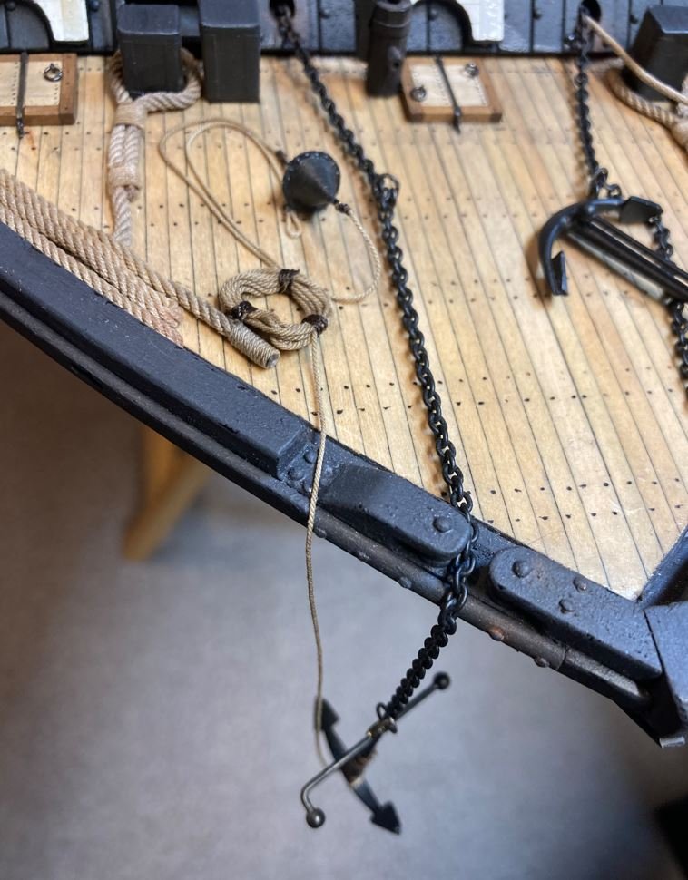
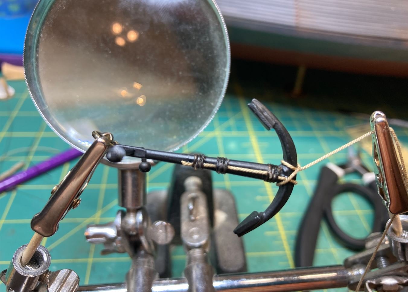
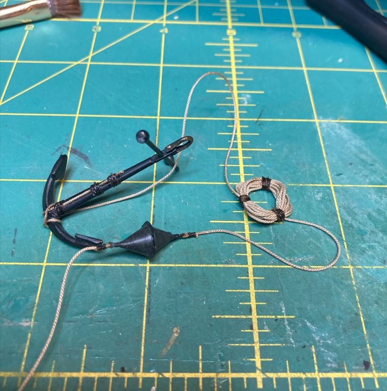
Thank you all for your kind words and likes. The continued support is what helps keep me going. I think I have resolved my anchor buoy conundrum. There just isn't a lot of information on the Brown Water Navy in regards to the ships anchors that I was able to find. I finally resorted to researching the Blue Water Navy and the many models that were built of ships from the mid-19th century. There were many different methods used to secure the anchor buoy to the anchor, and I found many pictures of them (they were not posted here due to copyright rules) so I just picked the one that I though looked best. This is the solution that I came up with. The rig that had the buoy rope secured around the arm and the shank had the most appeal to me so I ran with it. Securing the rope to the shank. Anchor, buoy, and rope coil completed. Assembly installed on the foredeck. Hopefully I got this right. If not, at least it's easy to access and fix. -Brian
- 739 replies
-
- 23
-
-

-
@Keith Black @BANYAN @tlee01 @Cathead @Canute Thank you all for the kind words and continued support. -Brian
-
Thank you Mark. One never knows where it will end up. A museum would be a dream come true. Thank you Keith. This being my first scratch build, has definitely been a learning experience. I usually try to plan things out a little better but sometimes I just get an idea in my head and jump right into it. Sometimes it works, sometimes it doesn’t. I must say that I have been pretty fortunate that most of the times that I have dove headlong into a project on this build, it has worked out. However, there have been those times that I have failed miserably. To avoid my embarrassment in those times I have chosen not to post those screwups. Scratch build are definitely a totally different beast than kit builds. -Brian
-
Eberhard, I appreciate the input very much. I have been researching how the anchor buoys we’re rigged on the blue water navy ships of the time, and from what I have found so far, they show to either be hitched to the cross-point of the stock and the shank at the top or around the shank and the arm at the bottom. I would think that the same methods would apply to the brown water navy, but I also wonder if the water depth of the rivers as compared to the oceans would have something to do with them being rigged differently. I’ll keep digging. -Brian
-
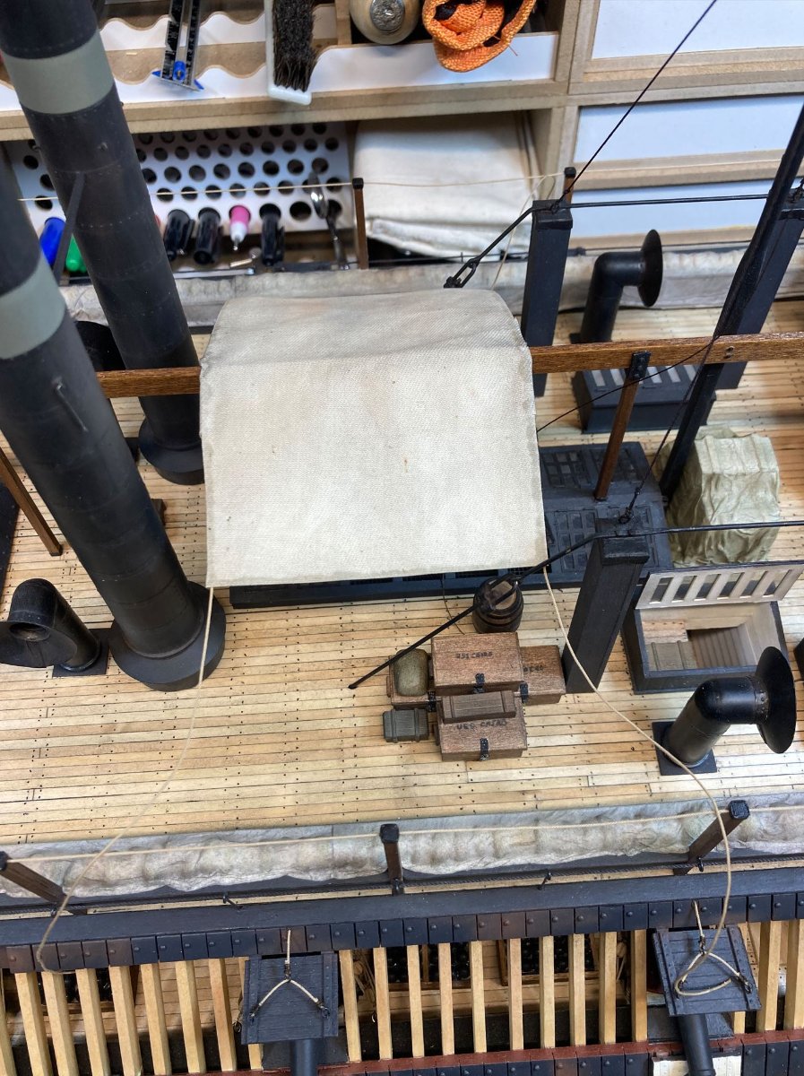
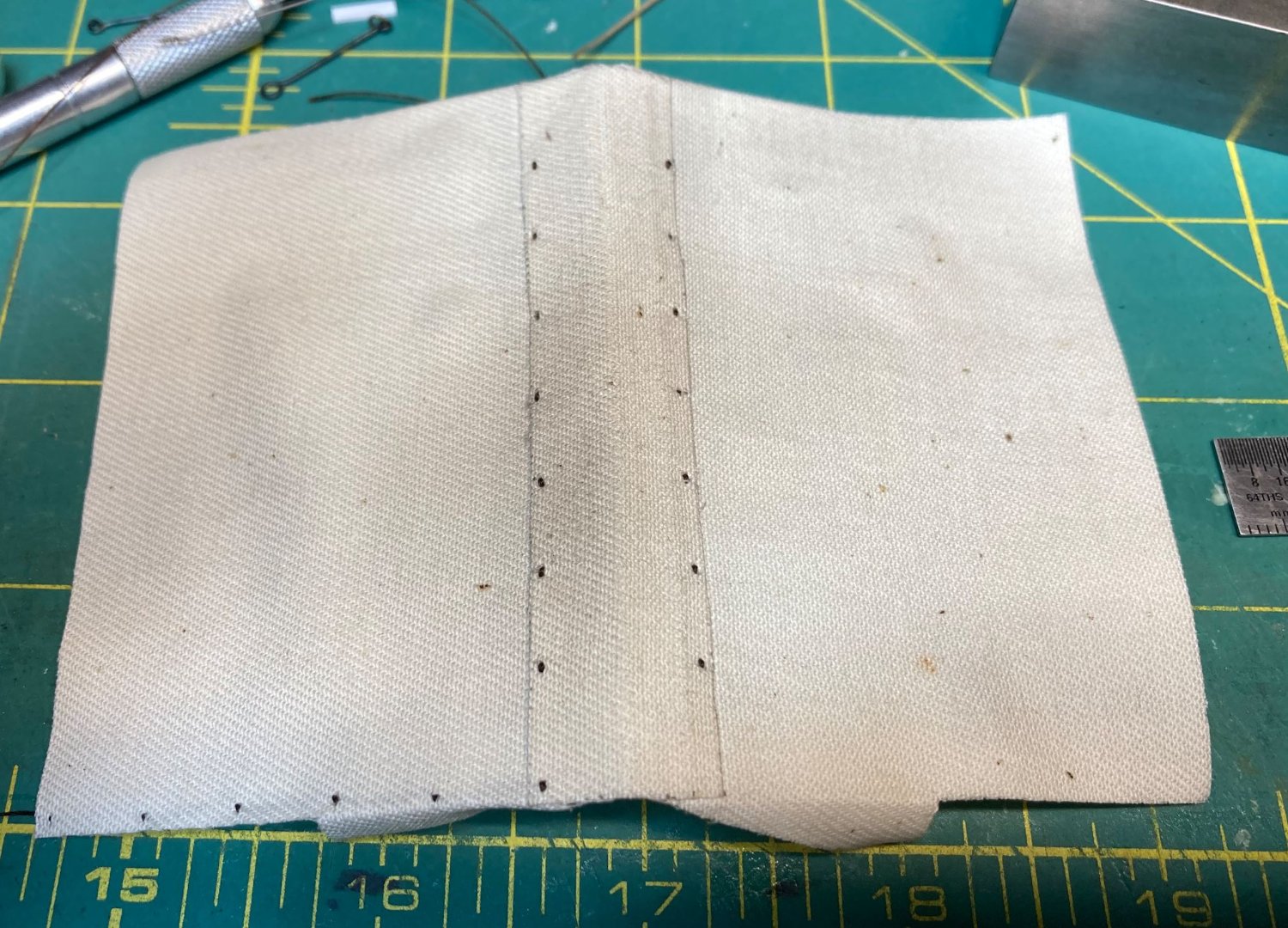
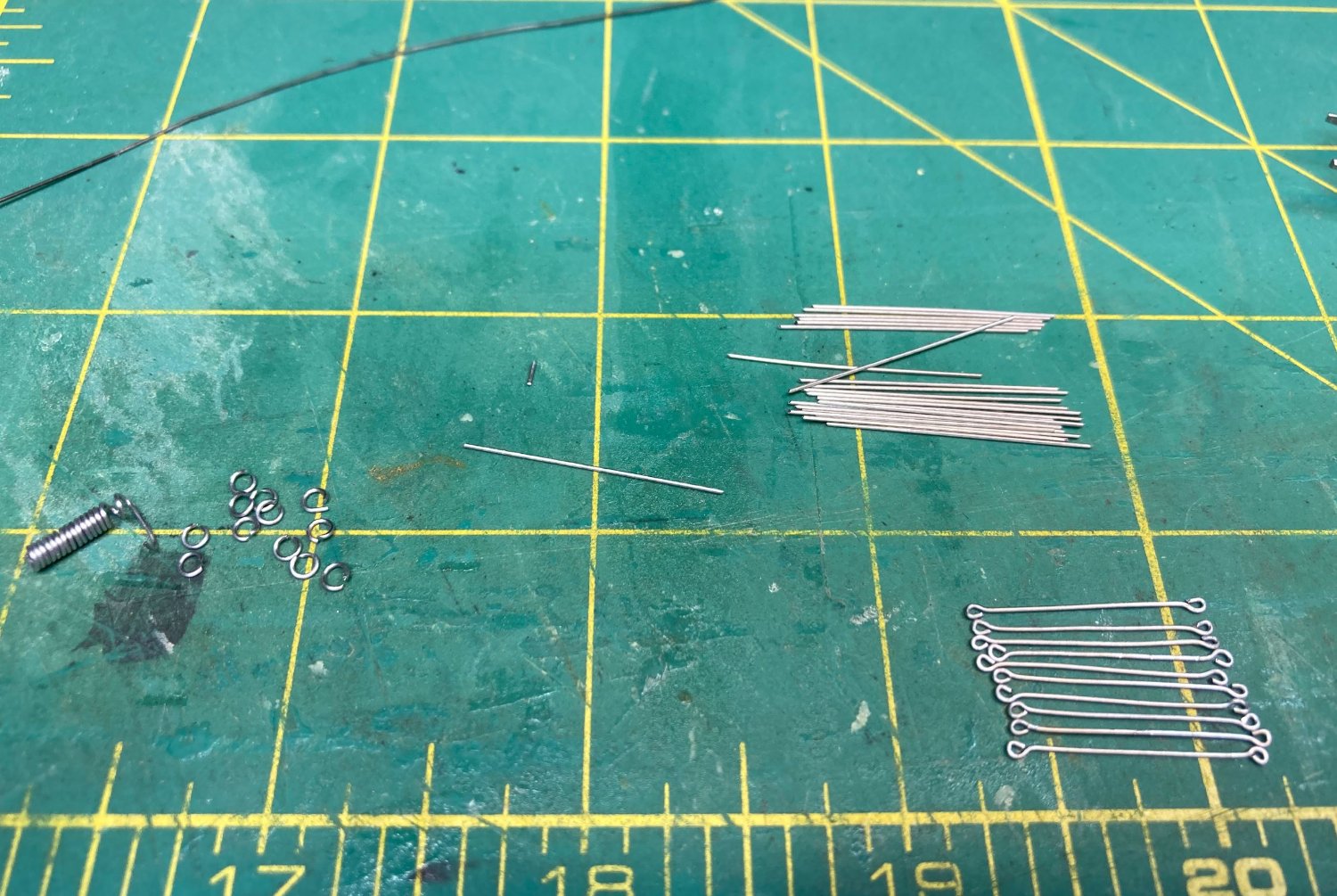
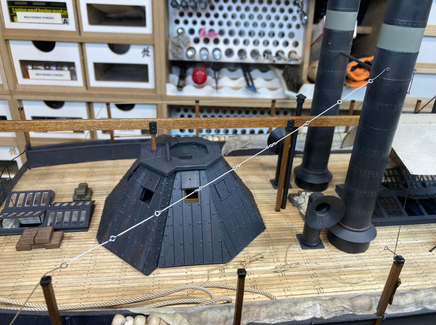
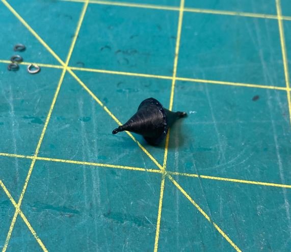
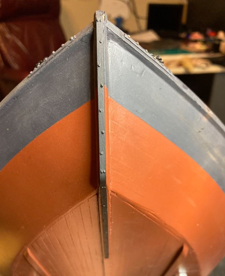
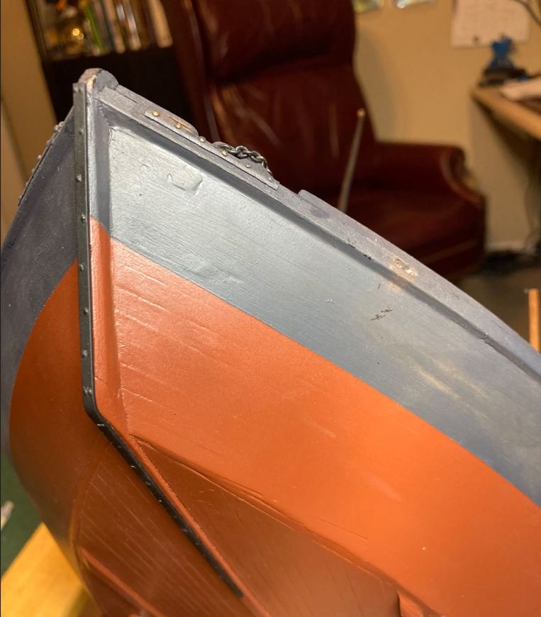
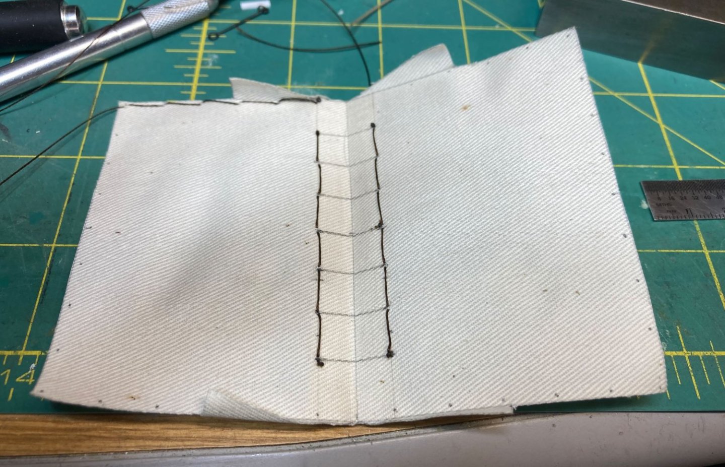
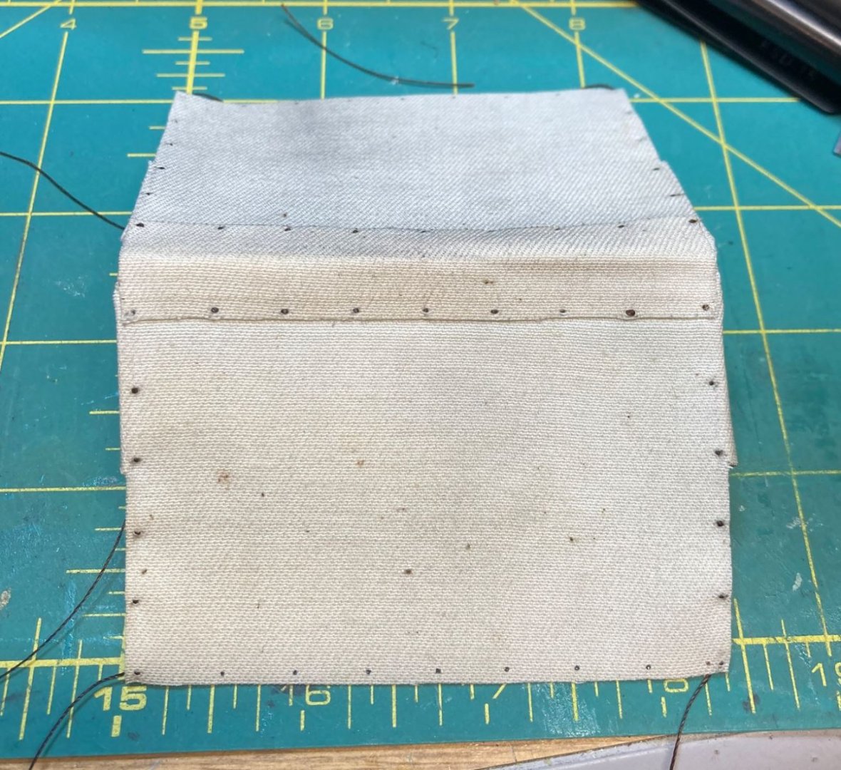
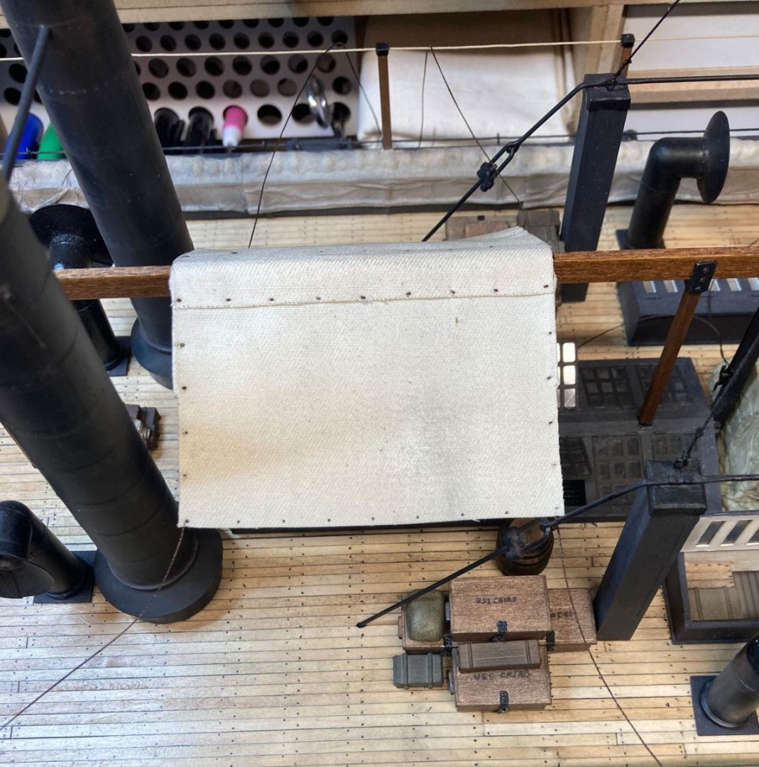
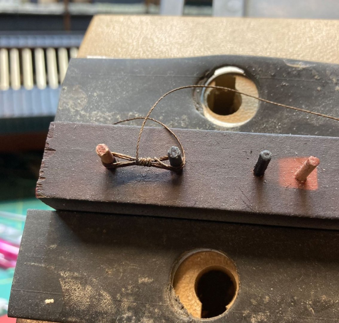
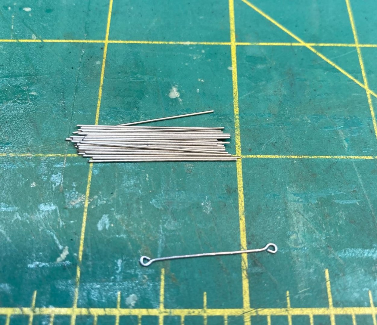
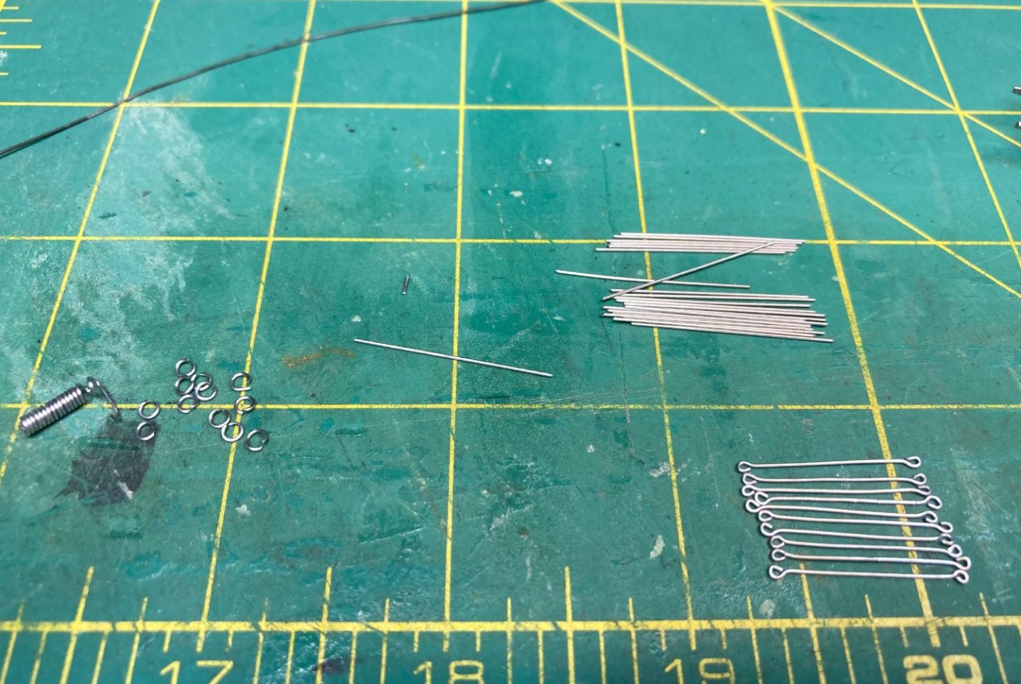
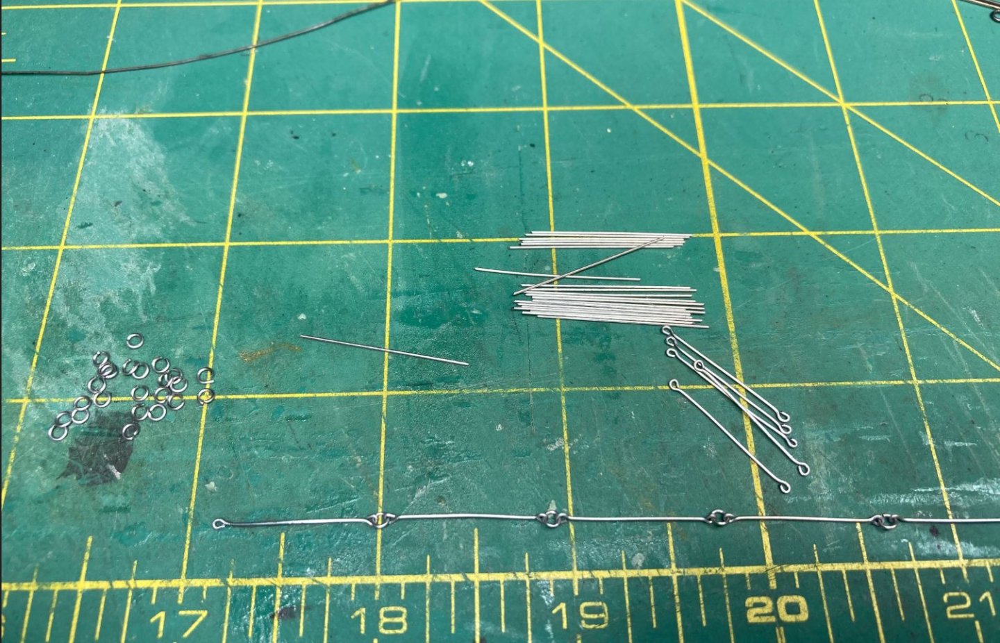
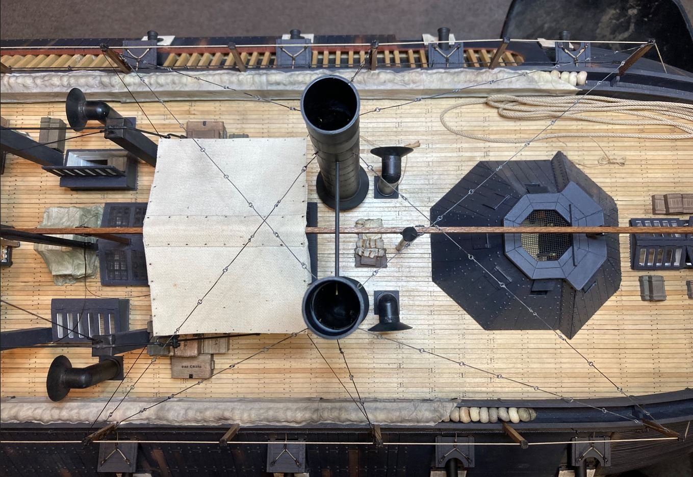
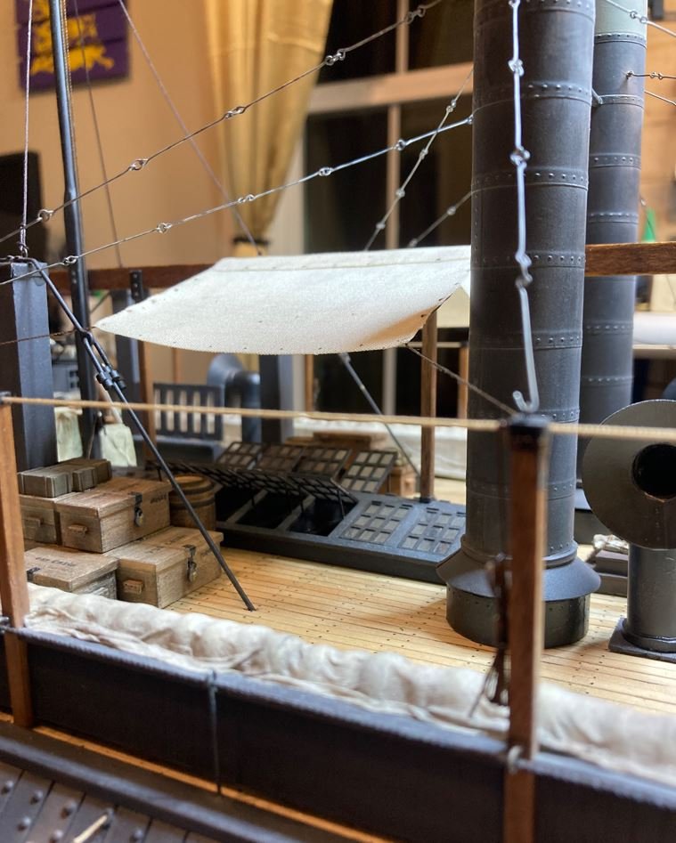
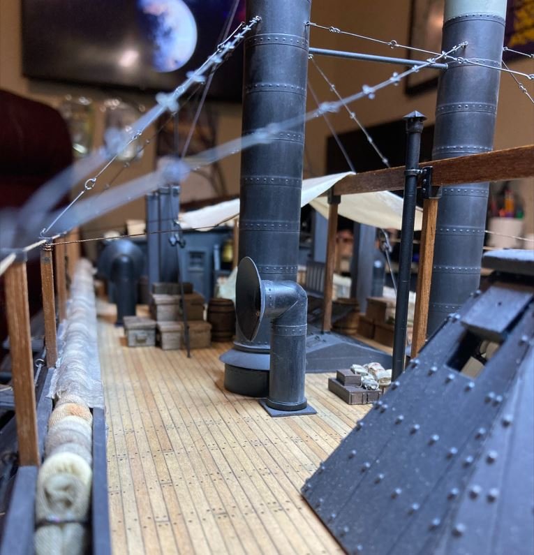
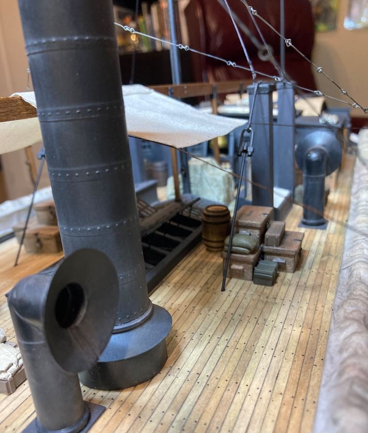
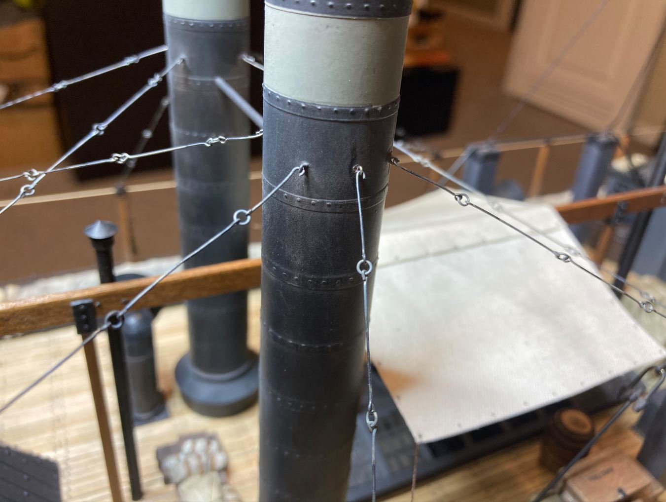
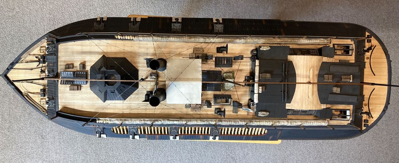
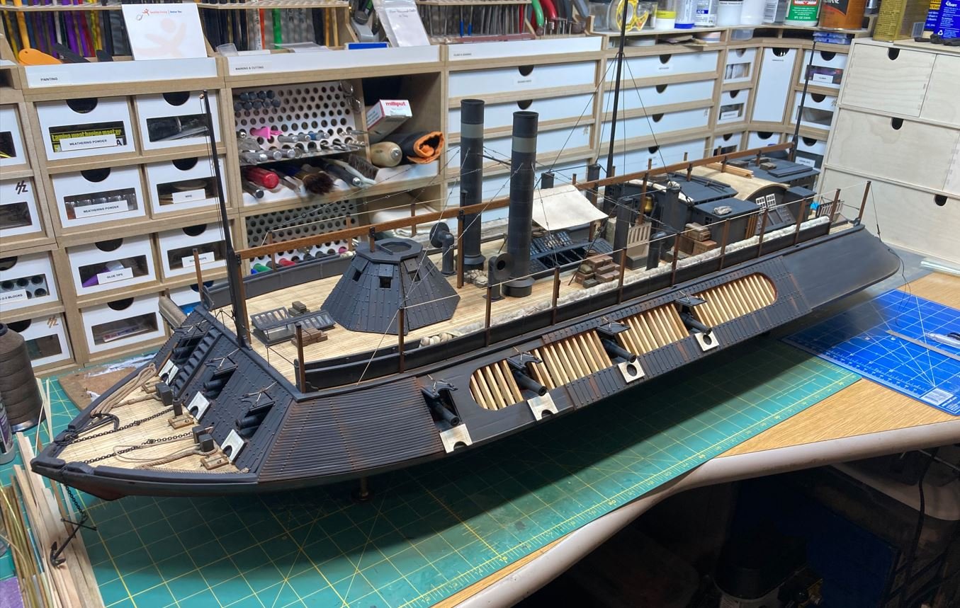
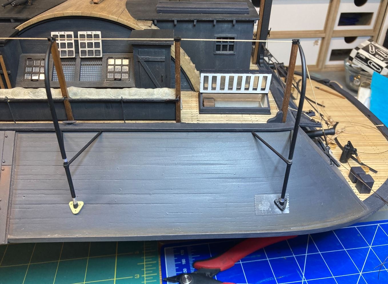
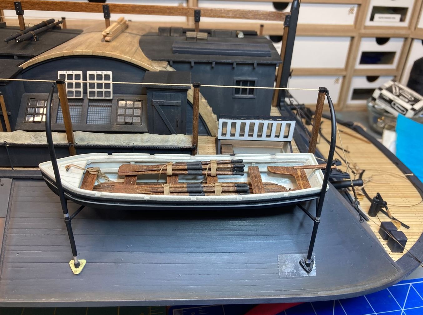
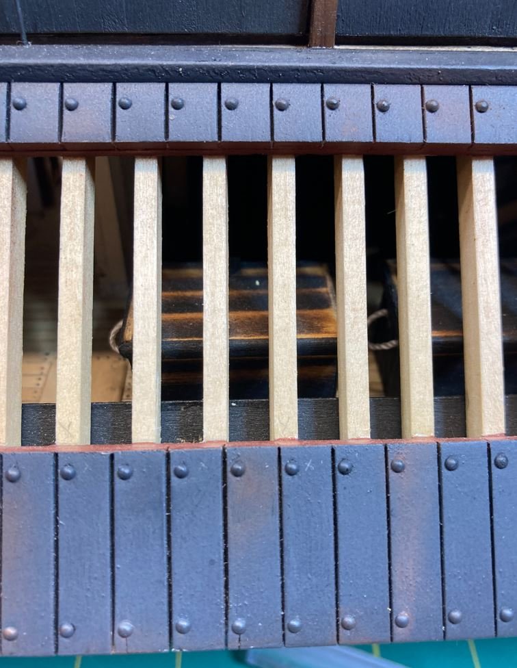
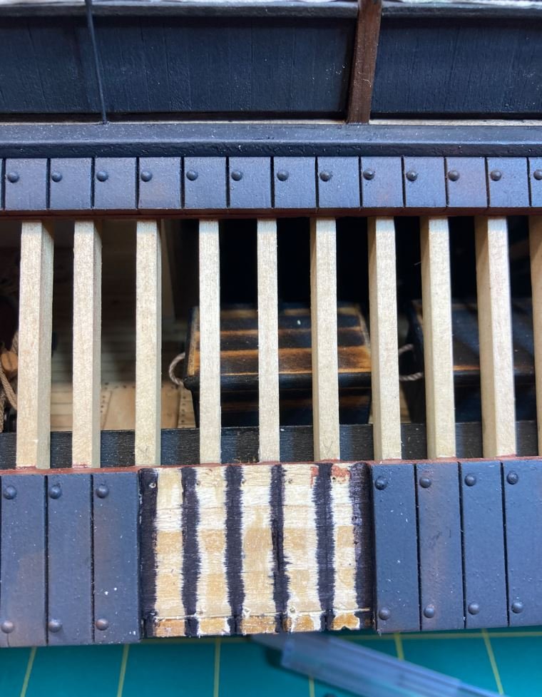
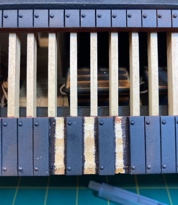
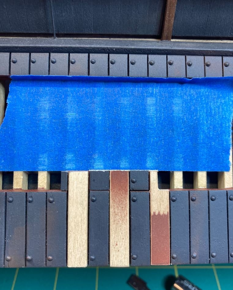
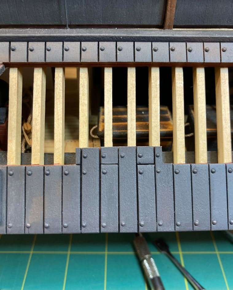
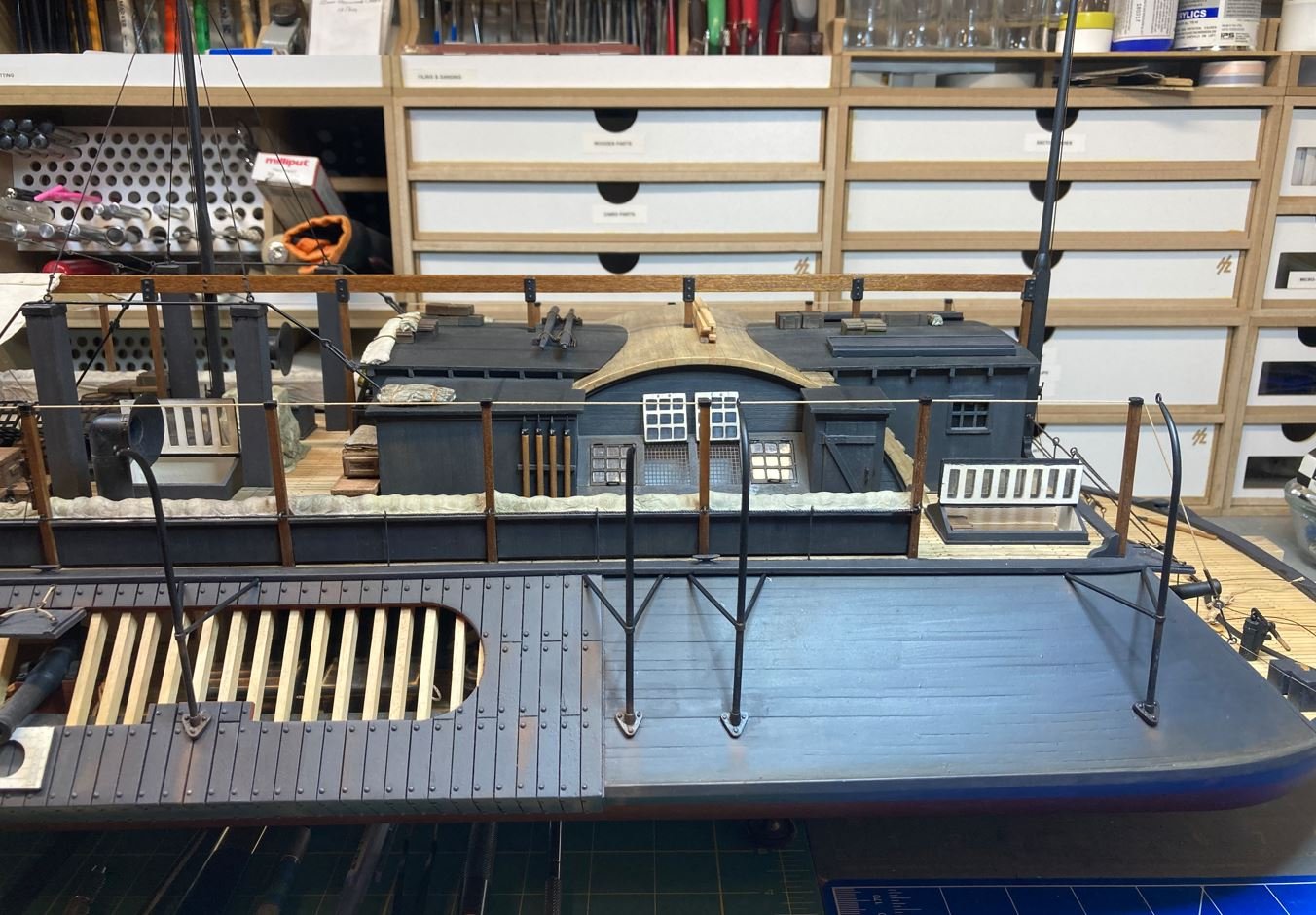
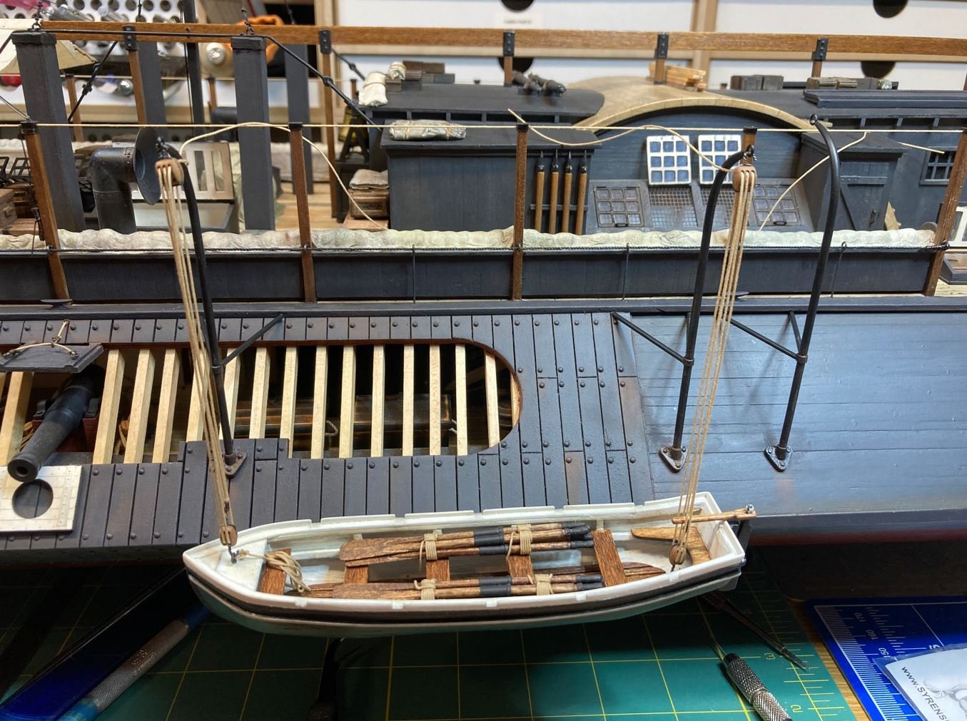
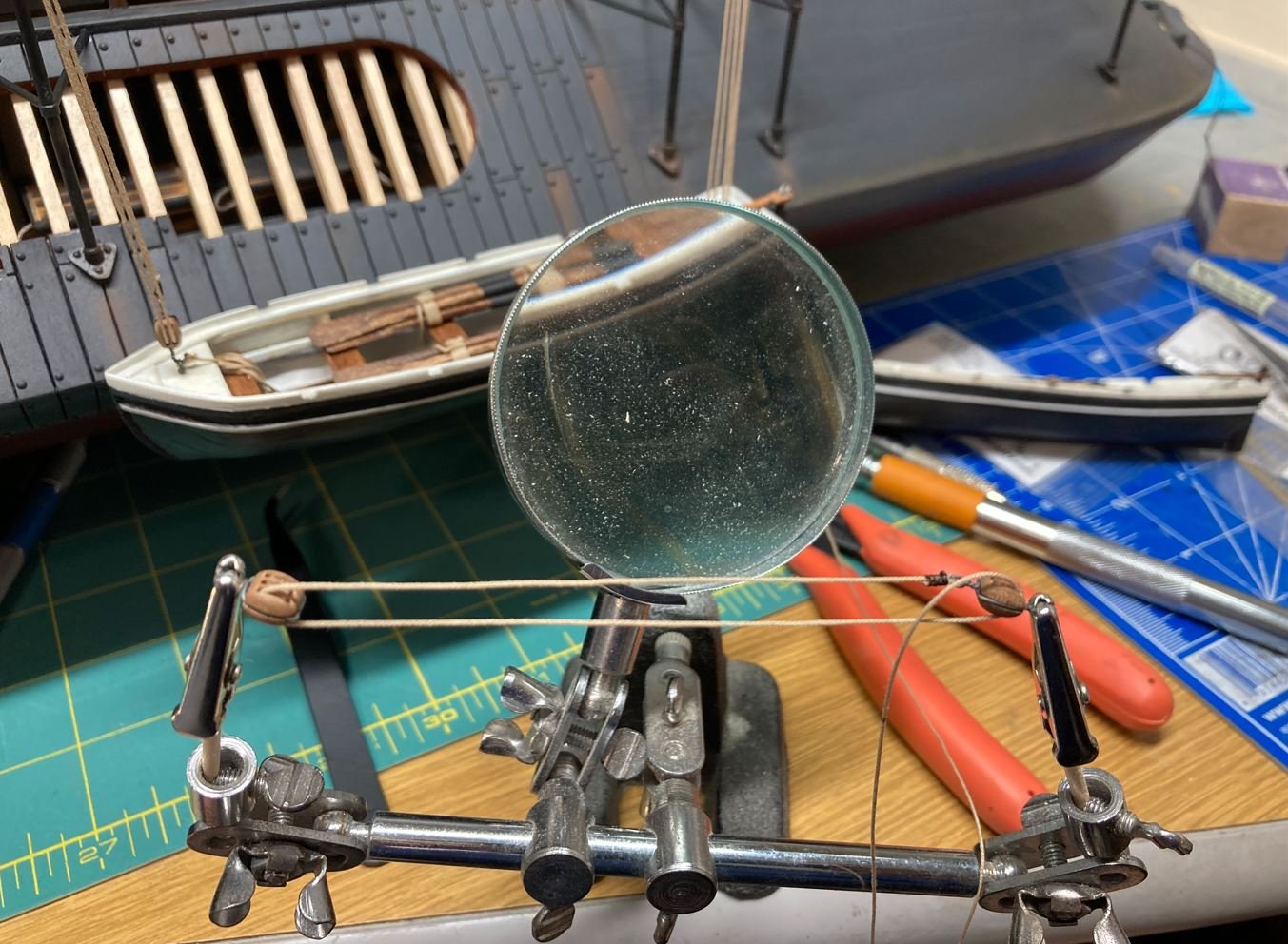
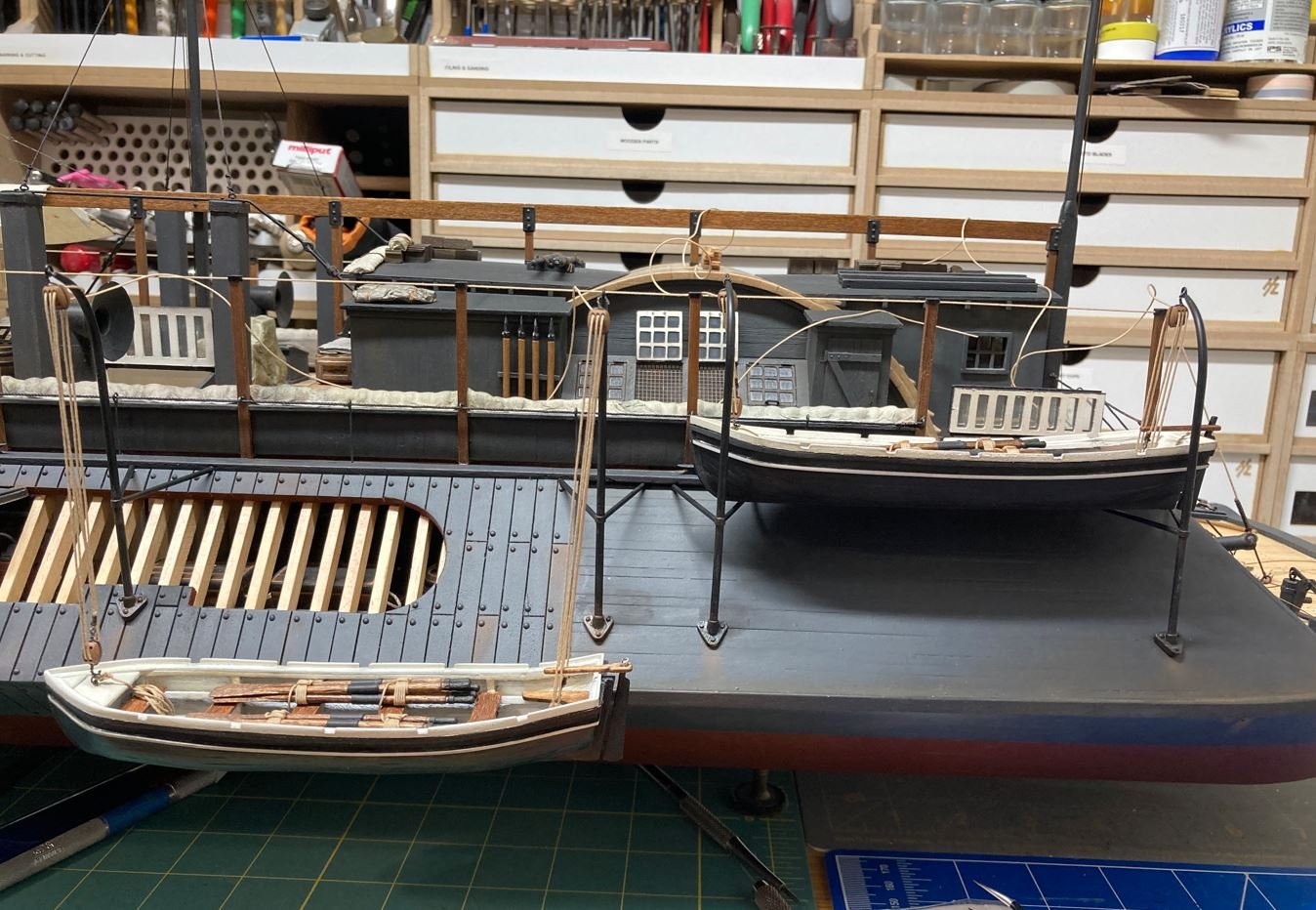
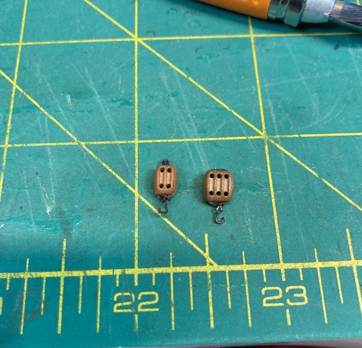
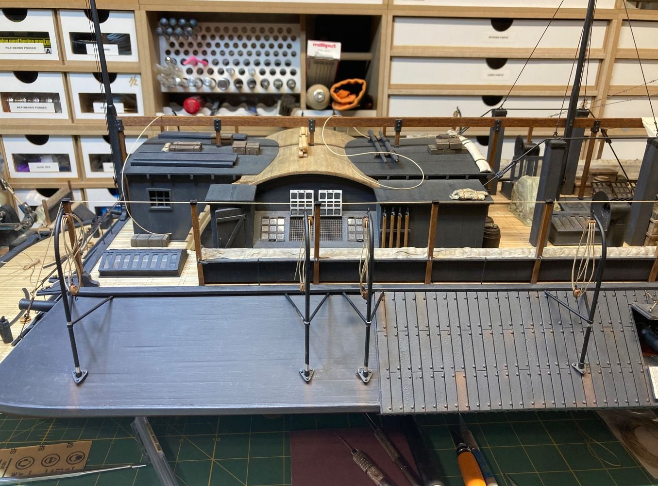
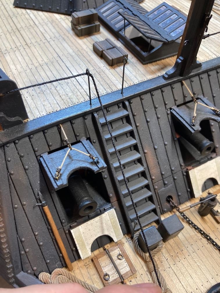
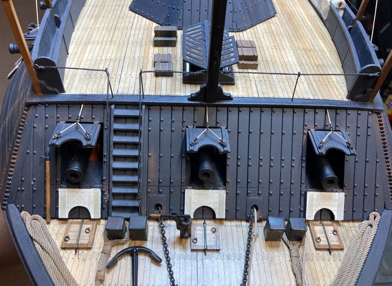
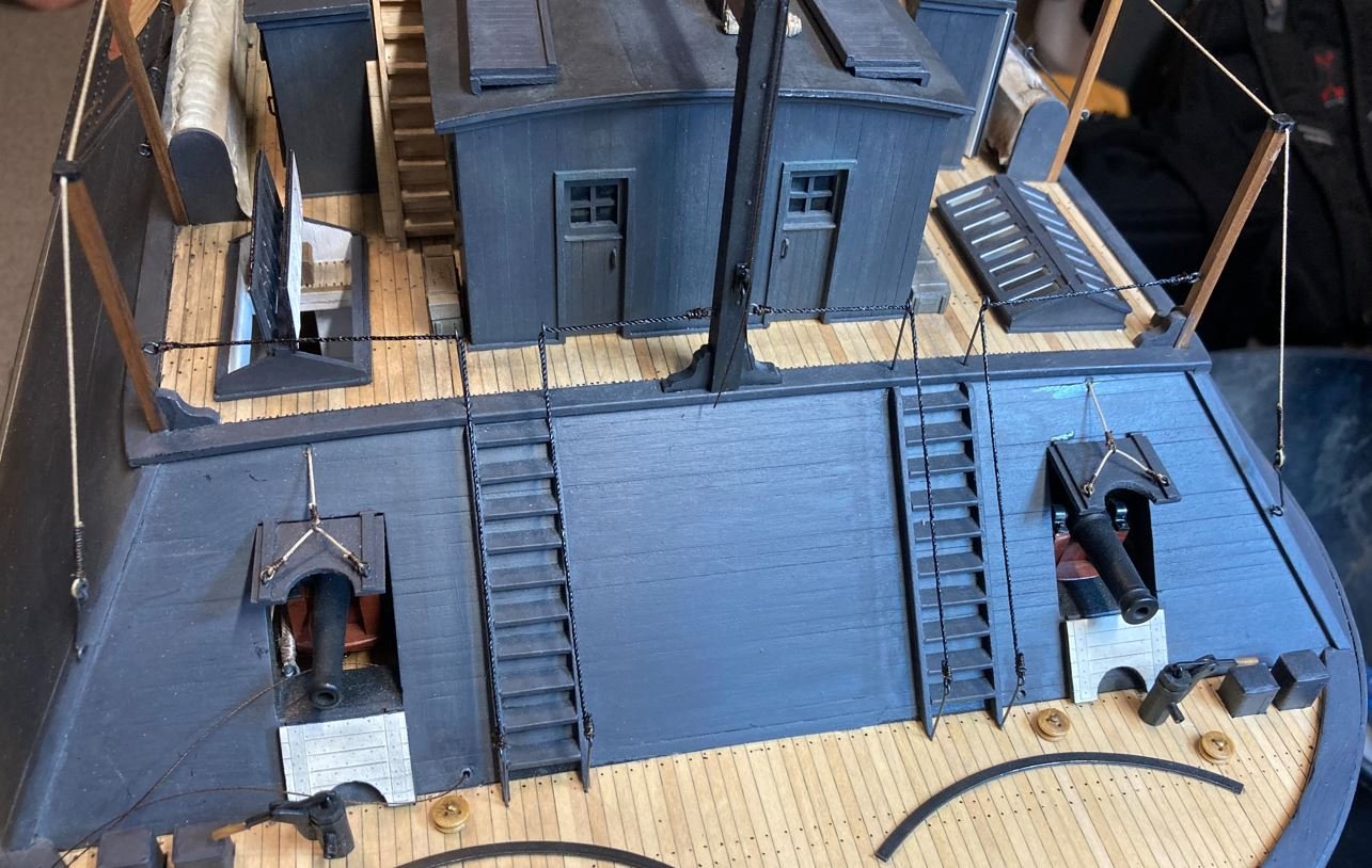
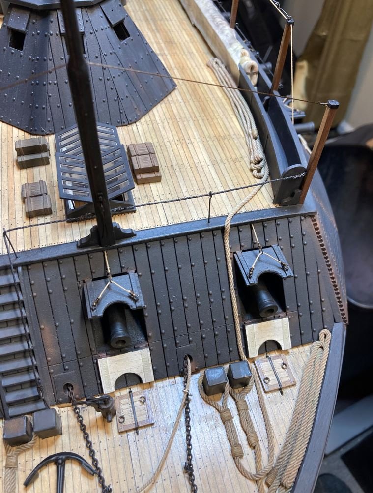
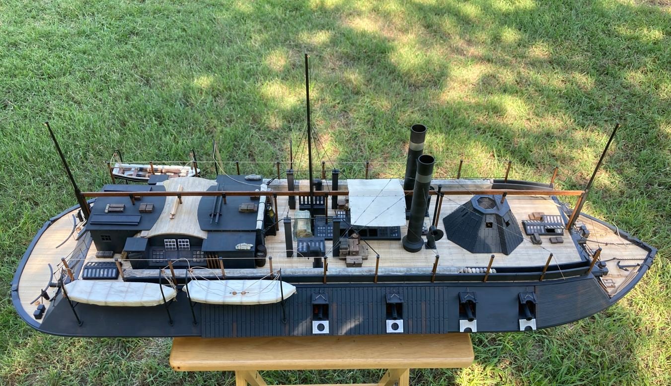
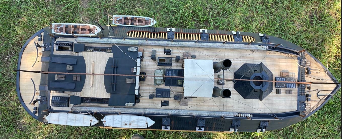
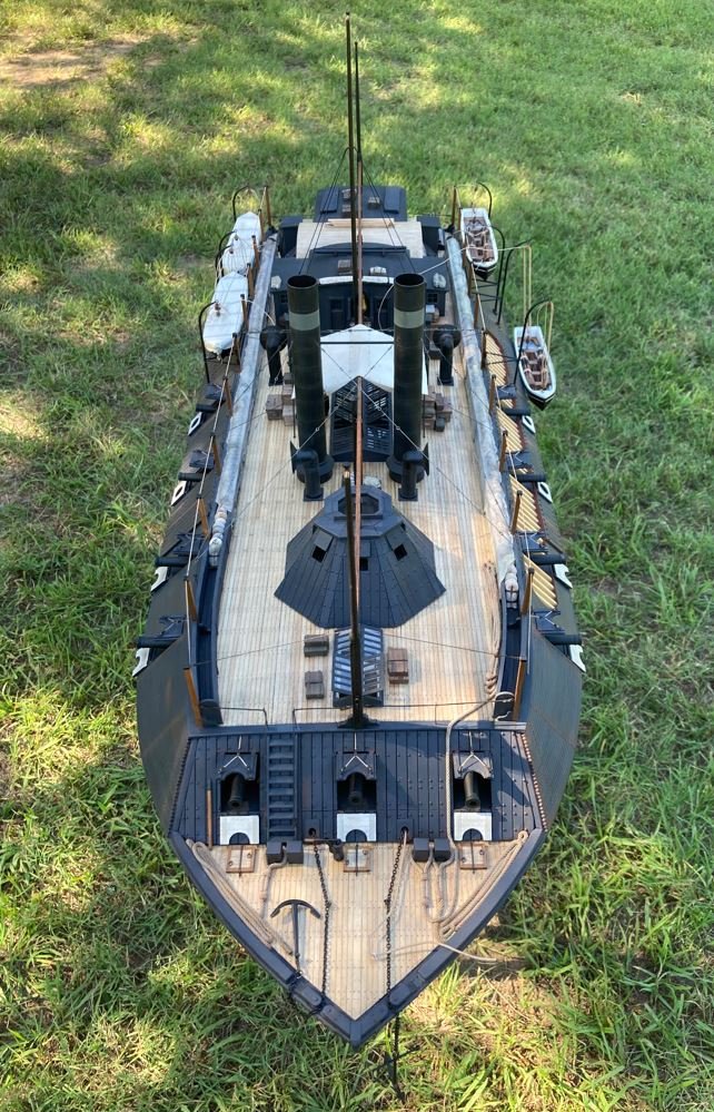
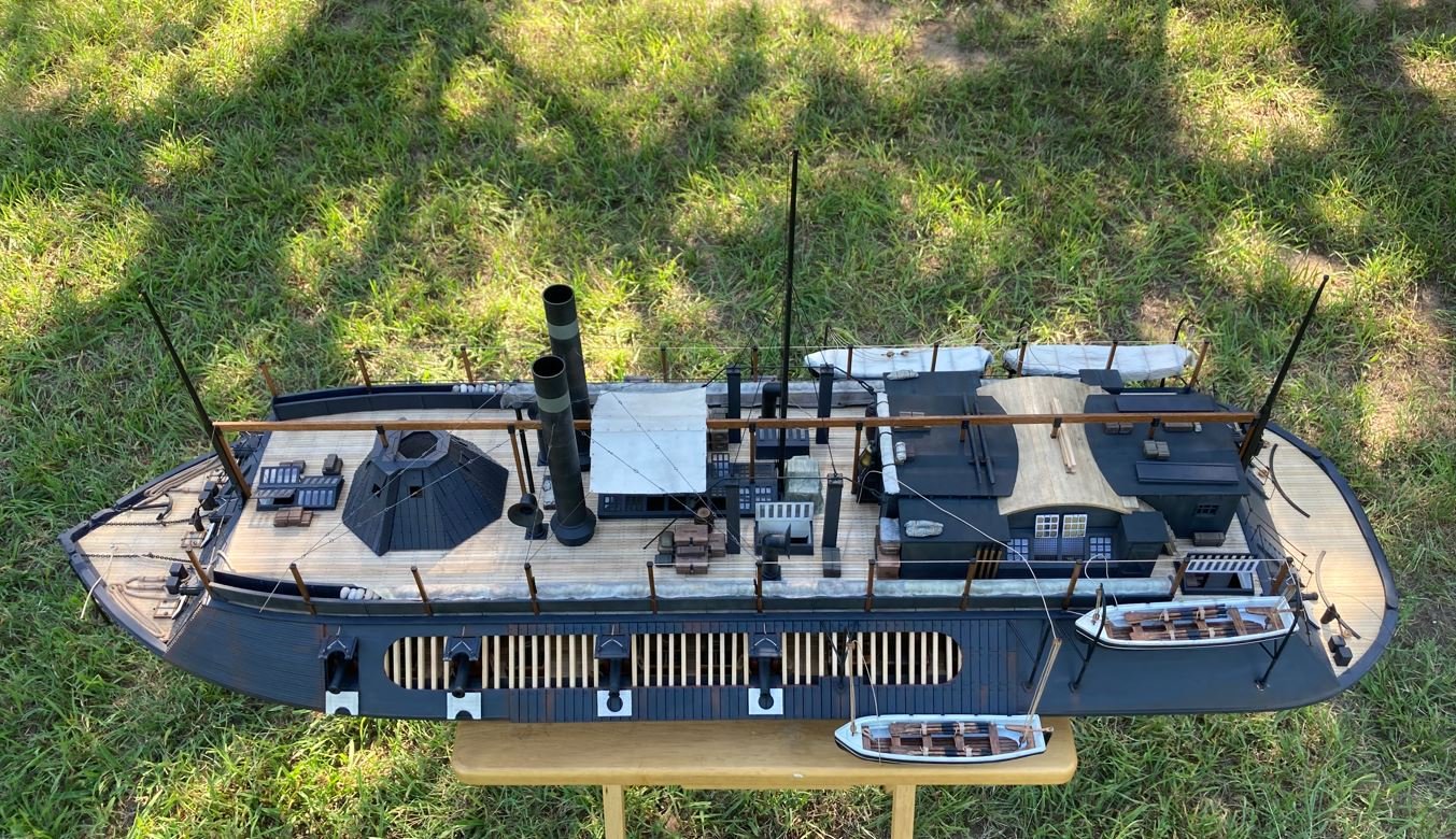
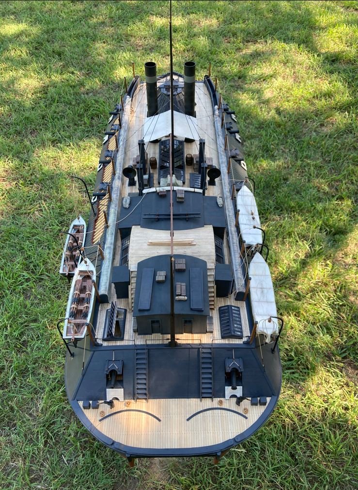
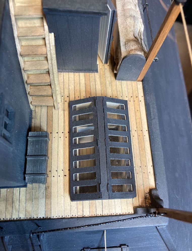
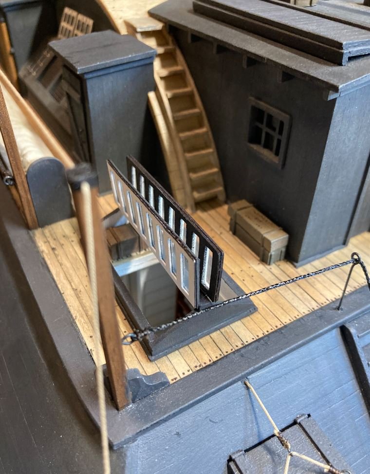
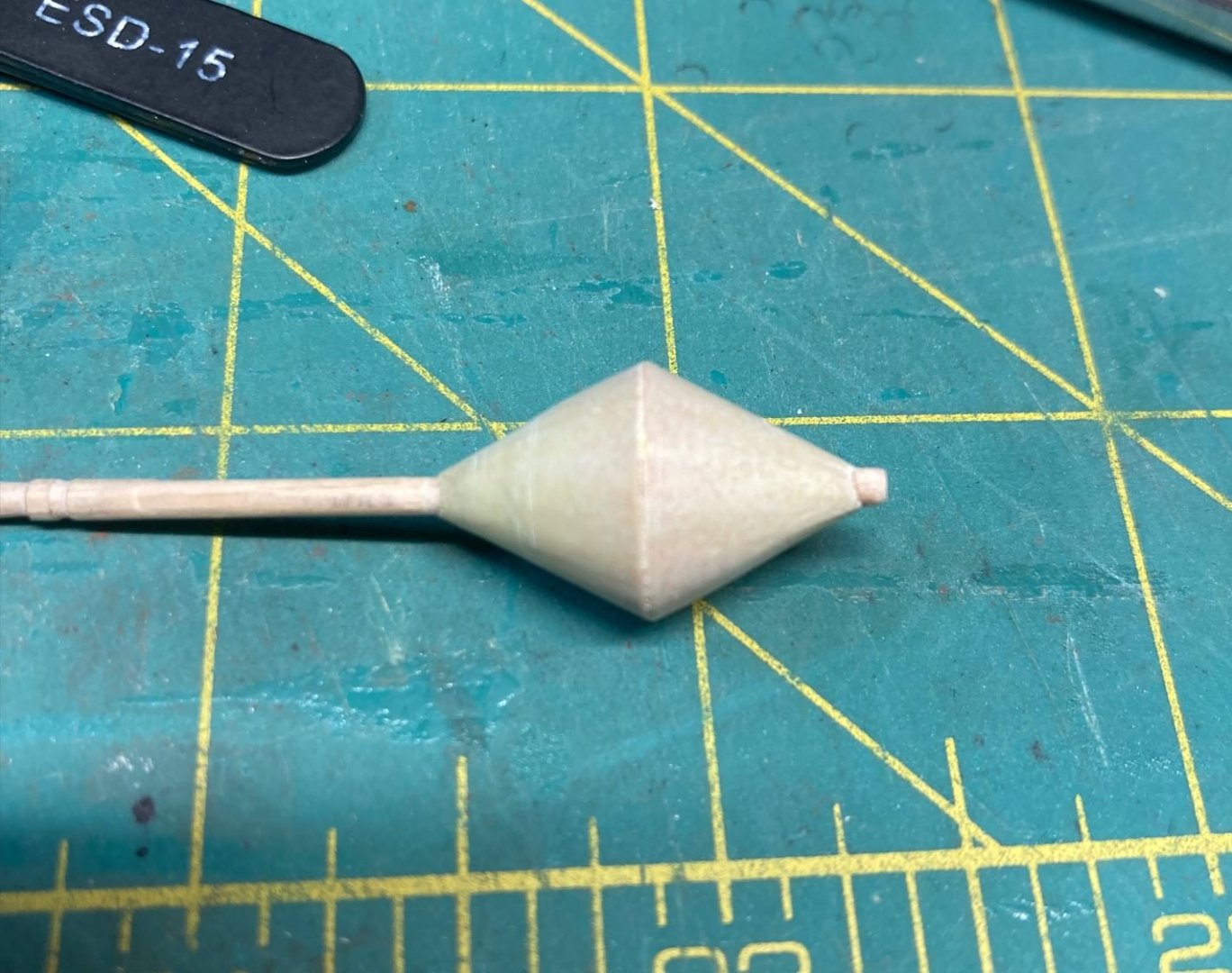
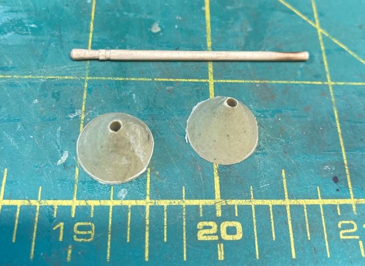
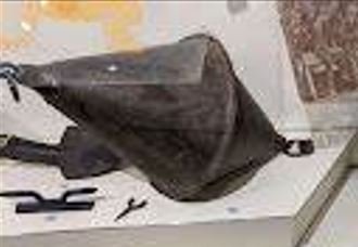
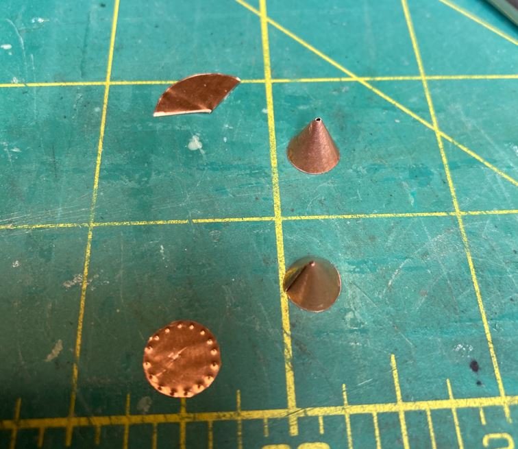
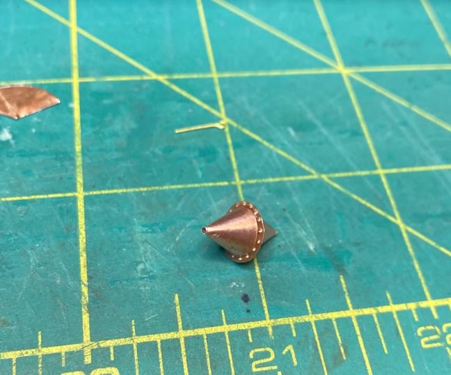
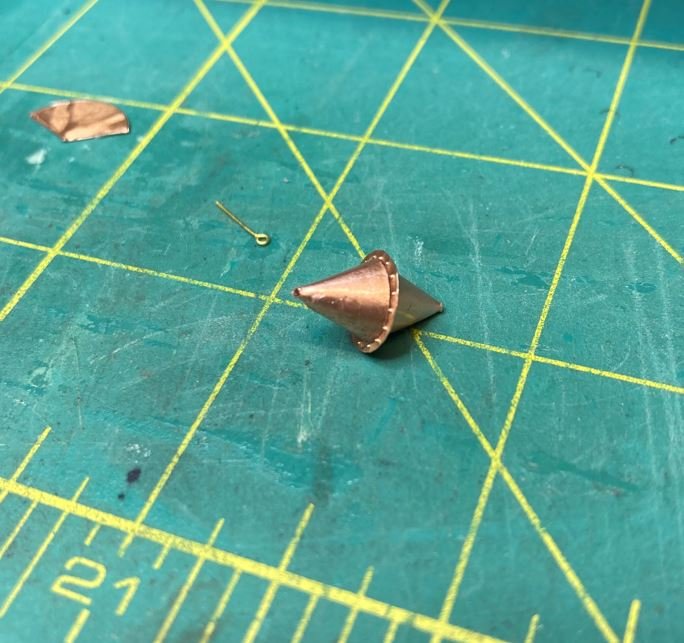
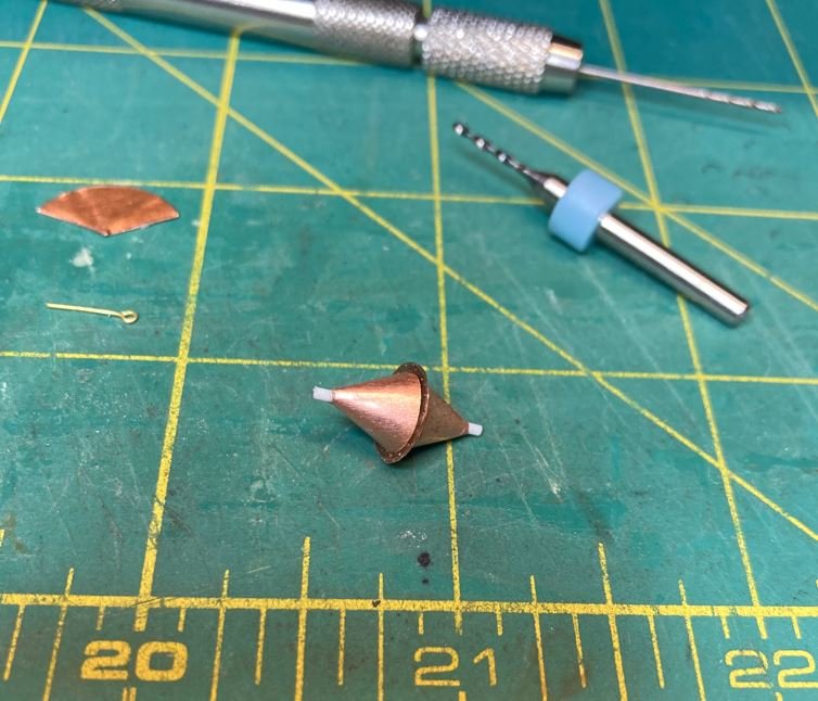
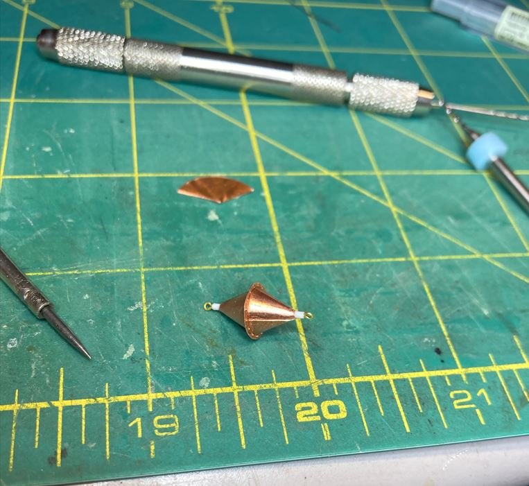
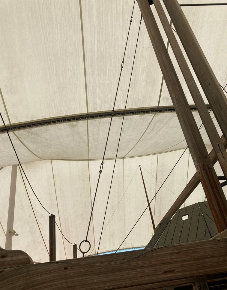
Hello again everyone, I'm ready with another Cairo update. Over the past few weeks I have been focusing on some of the detail work. I started off with the anchor buoy. This was one of the artifacts that was recovered during the salvage and sits on display in the Cairo museum. On my first attempt to make this I was going to try and make it from card stock shaped into two cones with a disk in the middle to form the flanges where the two halves met. I tried several times but just couldn't get the shape right. Since I wasn't sure of how this method was going to work, I didn't take any pictures. So, on my next attempt I tried using Milliput, getting the basic cone shape and then finishing it off on the lathe. Here are the two halves on this try. I drilled the center holes for the toothpick to align the halves together, but again I just couldn't get the shape I was looking for. For some reason the centerline wouldn't fall in the right place and I was having difficulties trying to figure out how I was going to make the center flange. So I ended up scrapping this version as well. On my final attempt I decided to go with some copper sheeting and the same method I originally used with the card stock. I scrounged up a few small scrap pieces in my scrap bin that I had left over from the chimney flanges (I throw nothing away) that worked perfectly. I managed to have enough to make the two halves and the center flange. Here are the two halves glued to the center flange. I fit a small piece of styrene rod through the middle to provide a mounting place for the eyebolts, then drilled a tiny hole in each end to receive the eyebolts. The eyebolts were then glued in place. and finally the whole assembly painted up. Before I can place these on the boat, I'll need to research how these were rigged to the anchor. I have a sneaky feeling that this is going to be a task to find info on these, but I'm going to see what I can turn up. Next it was on to installing the bow guard. Nothing too complex here, I had made this a while back and just needed to put it on. I left out a couple of the rivets to use a mounting points to give the guard a little more of a secure grip on the keel, than just gluing on. Then I moved on to the Hurricane Deck canopy. There are numerous contemporary photos of the Cairo's sister ships that show almost the entire Hurricane Deck covered with canopies, but the only photo of the Cairo has just one canopy over the boiler skylight. It is not known if the Cairo had more than this when she went down so I just went with what she had in the photo. Besides, too many canopies would hide a lot of the deck details. Attempt 1: I took a small piece of muslin and cut it to shape and size, but I was having a hard time keeping the edges from fraying. So I took some CA and ran it along the edges of the material to keep the strands in place. Definitely didn't like that look. The muslin had the texture that I was looking for so I stuck with that material. On my second attempt, I cut the canopy shape out, bit this time I soaked the whole thing in diluted clear Elmer's glue and let that dry. For added details, decided to put a ridge vent in the canopy since I figured that these were made up similarly to the field tents used on land by the Army. Then I went in and added the grommets for additional detail and used those as a way to cover the canopy guy ropes. Then the whole thing was installed along the center beam and the guys attached to the stanchions. Making up some of the rope coils for the canopy guys on the stanchions. Next, I wanted to finish up on the aft skylights and get the door installed. So it was back to borrowing the Admirals Cricut again to cut out the window frames. I built these up exactly the way I did the others and mounted the Port side open and the Starboard side closed. Next up, it was on to the forward and aft hand ropes for the casement ladders. Completed forward ropes. Completed aft ropes. Initially the ropes didn't sit right, they had a bit too much sag to them. So I ended up running a bead of CA along each one to stiffen it up and hold its shape. I think the overall look came out quite nicely. Next was the installation of the long hawser. This was probably the one that Commander Selfridge ordered tied to a tree on the Yazoo River bank when he had the ship ran aground shortly after the torpedoes blew the hole in Cairo's Port Bow. This hawser held long enough for everyone to abandon ship, before the tree was pulled from its rooting and the ship slipped beneath the surface. Then it was on to another one of the more tedious parts of the build. The chimney guys. The Cairo display has one set of these installed on the "Ghosted" chimneys with the rest being just steel cable. The original guys were actually iron rods and links (rings) that had a threaded loops on each end to adjust the tension. These guys can be made out in the old Cairo photograph, although some of the photos of her sister ships look more like they have cables or ropes holding the chimneys. I went ahead and built it like the photograph and because there were some of these recovered from the salvage. These are some of the original guys on the Cairo display. I started with some 24ga wire to make the rods. And bent them to shape as well as the rings. Tedious work. I had to make up 80 of the rods and rings along with 20 hooks for the anchor points on the chimney and stanchions. Once they were made to length, I heated them up red hot with my torch to give them that blued steel look. This color works nicely with the casement color. All guys in place and blued. I took a lot of pictures of these, I guess you could say that I was somewhat proud of how they turned out. After making up all of those links, I needed a break. So it was time to do a little cleaning of the work bench before moving on to the next project. So after a good bench cleaning I moved on to another tedious project, installation of the boat davits. Normally this wouldn't be too big of an issue, except the slanted casements of the ships make the task a bit more challenging when it comes to getting the davits all lined up properly. And since one of the davits on each side sits on top of the armor plating, it makes it that much more difficult to get the height and alignment correct. I started with the Port aft davits first. This wasn't too terribly difficult. I used some double sided tape to temp install the mounts then slowly nibbled away at the bottom of each davit until I got the proper height and location. Test fitting the boats to make sure there is enough clearance. Once the aft davits were installed, that was where I ran into an unforeseen issue. When I first started this build I had not planned on doing a whole lot of internal details since it was going to be a static model with all sides enclosed. As I built the details on the gun deck I decided that I wanted to show off some of these details and decided to make the Port side a cutaway. Well poor planning on my part didn't take into consideration that one of the davits was going to fall inside the cutaway. So when I built the cutaway I just mounted a small scrap of wood between the casement frames and figured I would just mount the davit base on that. Well, I didn't like that look, so change of plans. This is the area where the davit base will go. What I decided to do was to build up the armor plating in the area and mount the davit properly. So I pulled off the armor plating to make sure the panels lined up the way they were supposed to. Then I offset every other one to cover the area for the base mount. Gave everything a fresh coat of paint and some rivets. Then it was on to mounting the forward Port davits. Now it was time to rig the boats and temp install them. Started of with stropping the blocks. Then running the ropes through them. One boat in place. I wanted to show this boat as in the process of being launched, due to it's location above the cutaway. Placing it in it's stowed position would have blocked part of the view in the cutaway and I wanted to give the build a bit of action, not just a static model. Both Port boats in place. I need to find a way to stiffen the ropes so that they look like they have a load on them. The boats just aren't heavy enough to keep the line taught. I think a little diluted Elmer's will work. I also think it will also help keep the boats from swinging around too much when I move it. Now it's on to installing the Starboard davits. Pretty much the same as the Port side. Now with the rigging all in place I need to find out how they would have stowed the tackle on the covered boats since my Starboard boats have tarps over them and the lift rings are under the tarp. More research. Finally, she was getting a little dusty so I decided to take her outside to the barn and blow some of the dust off of her. It was such a pretty day out, I figured I'd snap a few pictures of her in natural lighting while I was out there. She's getting pretty close to being done. Perhaps a couple of more months and I will call it complete. Most of that depends on how much more research I need to do to get info on the anchor buoy, boat rig and rudder linkage. There is no rush, I'd like to finish by December 12th to celebrate the 160th anniversary of her sinking, but if I don't make it, so be it. I thank you all for the kind words, comments and likes, as well as taking the time to stop by and view my build. Until the next update, everyone stay safe and healthy. -Brian


- 739 replies
-
- 17
-
-
-
Excellent work Keith. Call me weird or insane, but I love rigging. It’s one of my favorite parts of the build. Something about all the ropes going every which way just adds something to the lure of ships. -Brian