


bartley
-
Posts
424 -
Joined
-
Last visited
Content Type
Profiles
Forums
Gallery
Events
Everything posted by bartley
-
Sorry for hijacking Paul's thread but I tried to give some guidance on serving issues here. It looks like Paul is using Gutterman 50 wt but lets wait to see if he confirms that/ Regards, John
-
Dave, Use about 1 part metabisulphate (Sparex} to 7 Parts water. It is not critical, Add the Sparex to the water. Not the other way round as it can be dangerous. Operation at 60 degrees Celsius for about 10 minutes is sufficient. Don't prolong the treatment because it is actually Itching the surface. If you want to dispose of the Sparex pour it slowly into a bicarbonate (baking soda) solution. It will fiz so do it slowly. You can then dispose of it down the drain, Wear gloves and eye protection throughout. It is not really dangerous chemistry but you don't want any of these things in your eyes and the blackening solution is actually poisonous, Regards, John
-
Dave, A couple of extra hints. The exact procedure you need to use depends on the state of the brass. Some is treated with lacquer and the purpose of the acetone is to remove this. Look at my post here. On the other hand if the brass has an oxide coating (which it usually does) acetone will not remove it. In this case you need to use metabusuphate ( Sparex). So a safe procedure is to do both. I use acetone first and then metabisulphate. If your brass is clean it should only take about 15 sec to blacken. If you leave it longer it will develop a flakiness which will rub off. You can terminate the Sparex cleaning with bicarbonate. Then wash with water. In case you are interested I dealt with the chemistry here. John
-
Dave, There is lots of info on this site about this - including stuff from me!. Search for "blackening revisited" for example. John
-
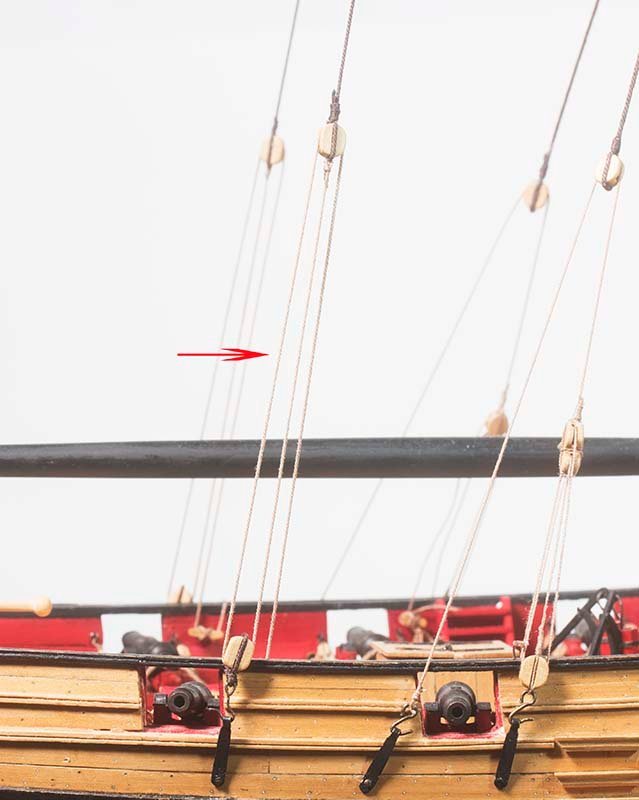
Post 67: Topmast Backstays Chuck points out that on contemporary models these are seldom shown as rigged. I decided to rig mine for two reasons. First a practical one. If the topmast sail were deployed then the physics would demand that these backstay swere rigged in order to avoid damage to the topmast itself. The second reason is, I suppose an aesthetic one. If they are not rigged the aft chain plate is vacant. These run from the upper topmast to a block above the deck. A tacle is then rigged tpo a block attsched to a hook on the chanplate an thence to a cleat in the aft of the ship. John
- 160 replies
-
- 5
-

-
- cheerful
- Syren Ship Model Company
- (and 1 more)
-
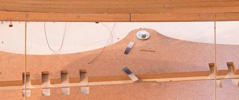
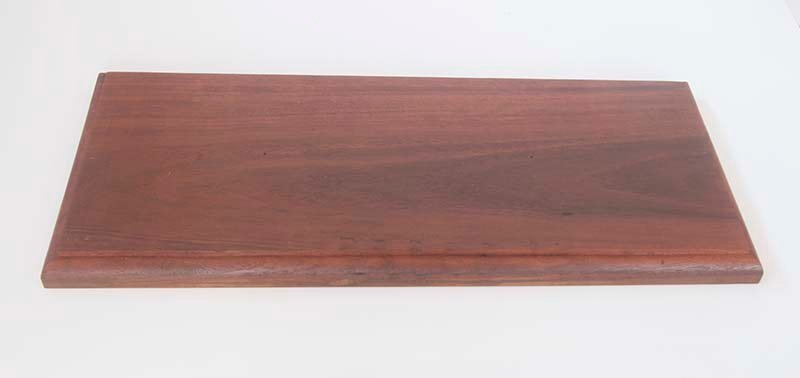
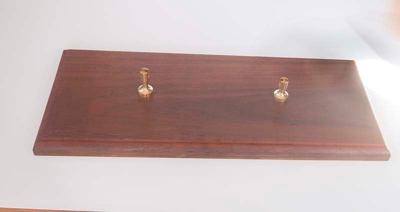
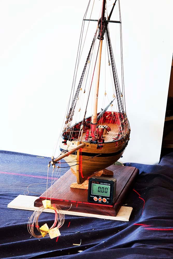
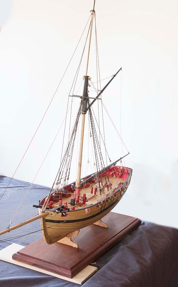
Post 66: Mounting Before proceeding further I felt I should finalize the mounting on a plinth. Captive nuts to take 1.4 mm brass threaded rod had been installed at the start of construction and the rod was now monted into these nuts: The plint was made from a plank of Australian hardwood which was given three coats of Danish OIl I have available the brass pedestals which many use: However for a wooden ship I prefer small wooden cradles. I was able to get the profiles pretty close because the mounting nuts were adjacent to bulkheads. These are just mock-ups at this stage as they wil eventually be the same colour as the plinth: So here is the ship mounted on the plinth: And the laser level indicates that the past is vertical with respect to the plinth: Next step is to install the yards whch were fabricated earlier. John

- 160 replies
-
- 6
-
-
- cheerful
- Syren Ship Model Company
- (and 1 more)
-
Glenn, Just one further thought. Be careful with chucks on these devices . They are quite massive compared to the device itself and sometimes do not run true for small bits. They tend to precess so the drill does not run radially but describes a small circle. So you may be better off with collets or use a Kyocera bit because they have 3 mm shafts. John
-
Glenn, I have used a Wecheer for some time now. It is rechargeable and has six speeds. The slowest very slow (about the same speed yo would use with a pin-vice) and great for working directly on the model where my Proxxon would be too large and aggressive. And it is very small (only 140 mm long). John
-
I actually like the variation in colour. I think it is closer to what real ships look like. In my opinion, when the planking is uniform in colour I think it looks a bit "plastic" John
-
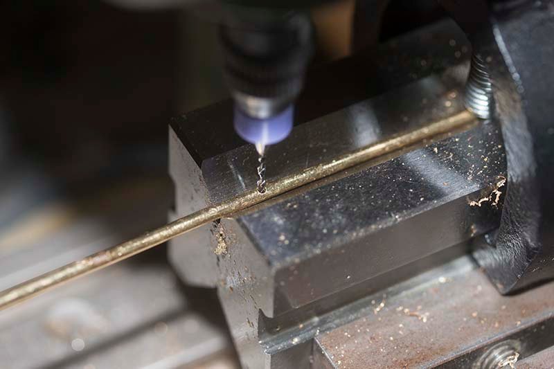
Brake Assembly Part 2 Before the brake assembly itself is installed, I glued on the forward anchoring bracket and the rear axle bracket to the chassis: The first part of the braking mechanism involves installing a metal bar which rotates to move the brake push rods . This bar is made from 2 mm diameter brass rod and needs to have 2 1mm holes drilled through it to connect to the push rods. I did this using a mill and a V block: The three clamps to hold this rod to the chassis were fabricated from 3mm brass strap: The instructions have this rod sit on top of the chassis breams but I chose to inset it slightly with a round file in order to locate it more firmly: The next task was to make the brake bar clamps - once again from 3 mm brass strap: These are nailed to the chassis beams. They are wider than the brake bar in order to allow it to slide: The final assembly will look like this: The next task is to construct the brake lever itself but I need to pause on this build while I return to complete my Cheerful build. I have been making a plinth and some rope for that and those tasks are now completed. John
- 82 replies
-
- 15
-
-
Thanks for your comments about my cheerful, Yes, for me the home made lathe works well but you have to be careful that everything is aligned. I bored all the boards in a stack and then the drill has to be clamped pretty well and must align with those holes. After that it will work well. I do have some larger bearings which I got from a local supplier but for the most part the cheap roller blade bearings work well. The Proxxon wood lathe is priced well but I did have a few issues with it which I think I mentioned in my post. I will be returning to Cheerful in a few days. I have been making a plinth and some rope and also started a build on a stage coach to try something different. Cheers, John
- 160 replies
-
- 1
-
-
- cheerful
- Syren Ship Model Company
- (and 1 more)
-
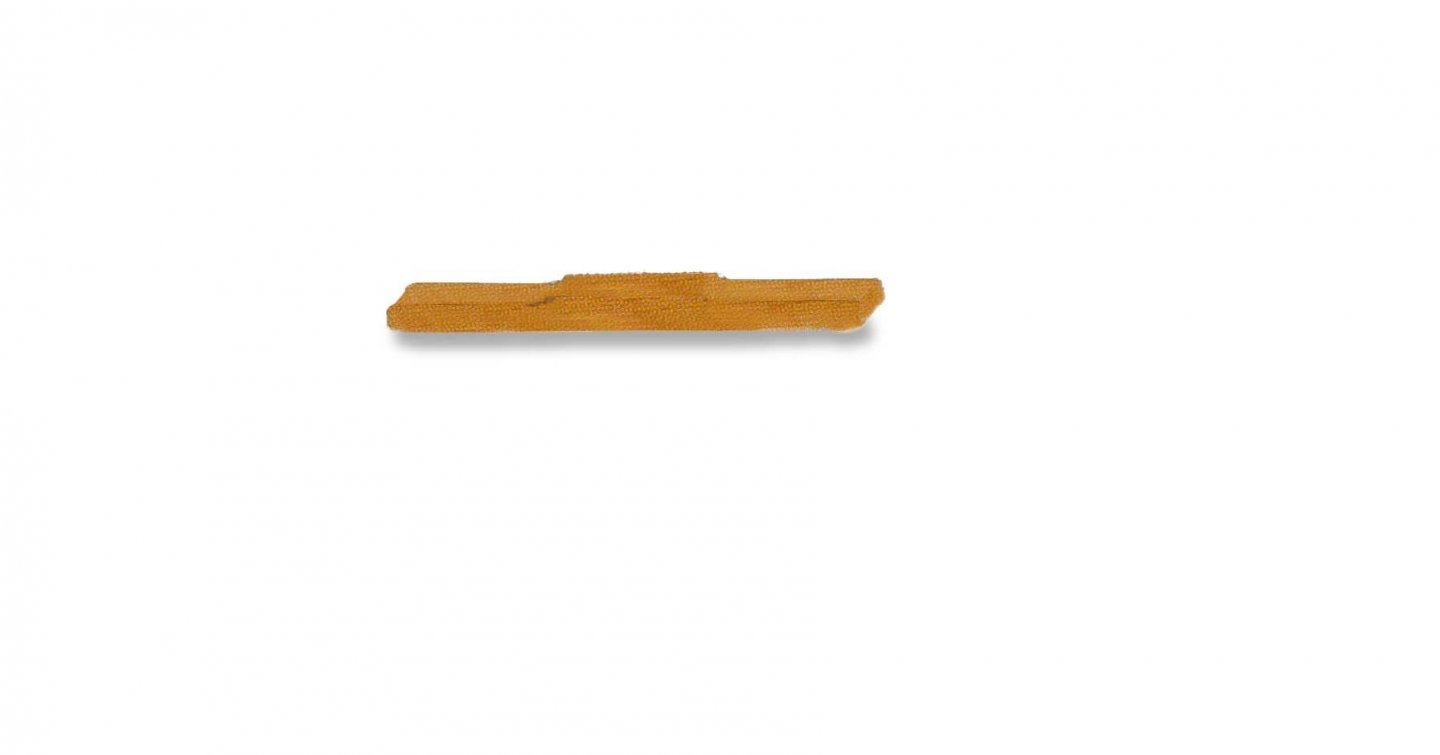
Brake Assembly The brake shoes are glued to the brake bar after making a cleft in the brake shoes as they would have been assembled in two parts. The two push-rods are then nailed to the brake bar: These will be assembled onto the main chassis in due course. John
- 82 replies
-
- 11
-
-
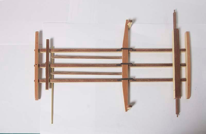
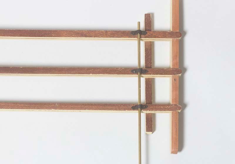
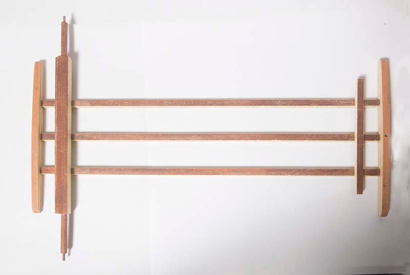
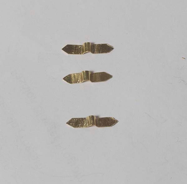
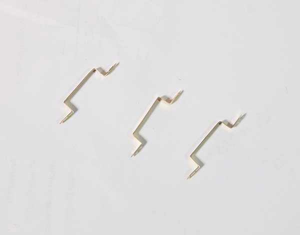
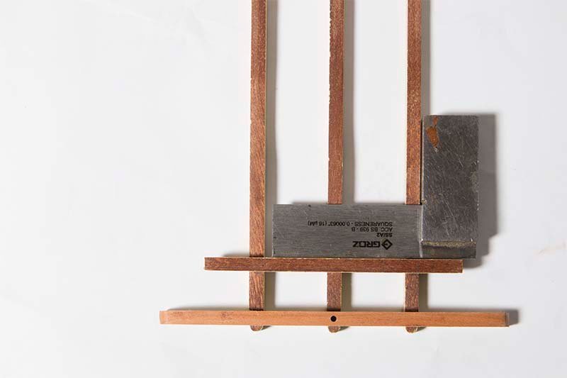
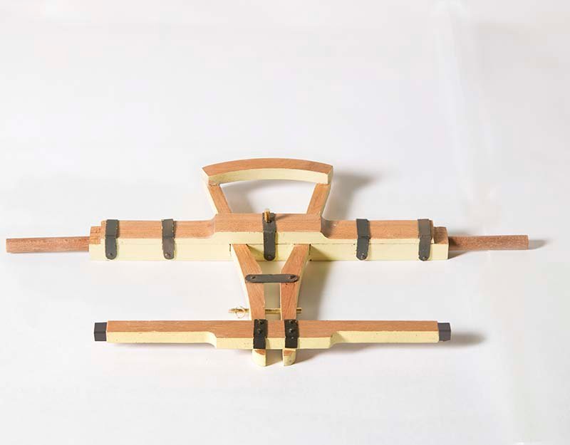
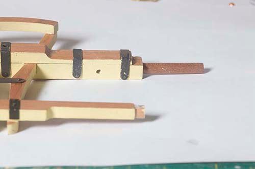
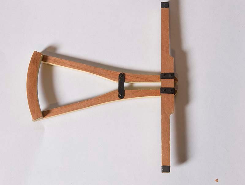
Steering Mechanism -Part 2 Quite a complex piece of woodwork this and it had to be strong because the horses were directly attached to this unit. First the axle bracket is made by gluing together two 4 mm parts Rebates are then cut into this unit to fit into the steering bars: on top of this is glued the steering bar: I neglected to photograph this stage but here is a photo of the unit after the metal clamps are added: The nest task to to add the metal struts which strengthen the haul bar. These run between the axle bracket. and the haul bar, Drilling the hole in the axle bracket to take these was tricky because no pin vice I had would fit between the two beams: Finally, both metal struts are in place to complete this unit: John
.jpg.a87a907bbab299e18550170a179b2821.jpg)
- 82 replies
-
- 11
-
-
Thinning Paint
bartley replied to Ed Gibbons's topic in Painting, finishing and weathering products and techniques
Yes Paul, I am a great fan of Vallejo paints as well. A good range of colours and, as you say, excellent brushing characteristics, I spray them when I can. As you know there "Game Air" range is designed for spraying but I mostly use the "Model Color" range. For brushing I dilute them by about 50% with their thinner and apply several coats. It is then hard to tell the difference between brushed and sprayed in my opinion. John -
Glenn, As a sometime painter this variation in a colour of the same name from different manufacturer is very common. Names are just a guide. there is no standardization. These days some manufacturers specify the Pantone reference or the CMYK values (which of course you can reproduce in Photoshop) and you will find they are very different. Many colours are still made from naturally occurring minerals. Red and yellow ochre for example. You don't have to travel very extensively to know that the ochre cliffs in different geographic regions vary enormously in colour. So the source a manufacturer chooses for his pigment will affect the resulting colour. So you will find "yellow ochre" varies enormously from one manufacturer to the next. John
- 857 replies
-
- 4
-
-
- Sphinx
- Vanguard Models
- (and 1 more)
-
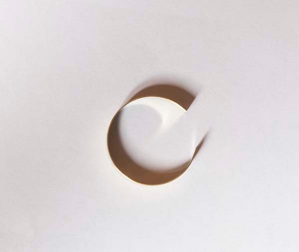
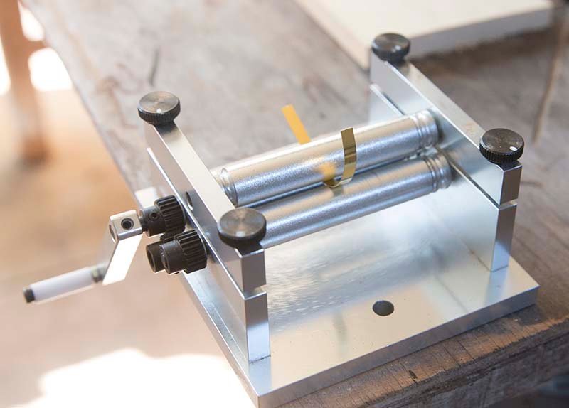
Wheels Part 2 In view of all of the information above about swaging, I thought it was time to but some "steel" treads and hub supports on my wheels. The tread is 5 mm X 1mm walnut which was bent into a rough curve using heat and a little water. It was stained with Japan Black spirit based stain and then glued to the rim of the wheel with CA: Reinforcing bands on the hubs were made from 4 mm brass strip. This was curved to shape using a mini rolling mill: A curve close the the correct diameter could be produced: The final shape could then be achieved by simply squeezing together a little more by hand. These bands were glued to the hub with CA. All of this metalwork was then blackened and weathered a bit so it looked like iron. This only one wheel - three to go! I also need to insert simulated bolts into the rim at each spoke position but I think I will complete my steering gear first. John
- 82 replies
-
- 13
-
-

-
Fascinating background information guys and thanks for all the likes. I am pleased there is so much interest. I thought that on a shipping site there might not be much interest in this project. I might need to lift my game! John
-
Bruce, Those bands on the ends of the draw bar would have been heat shrunk on I presume. Real blacksmith stuff that! John
-
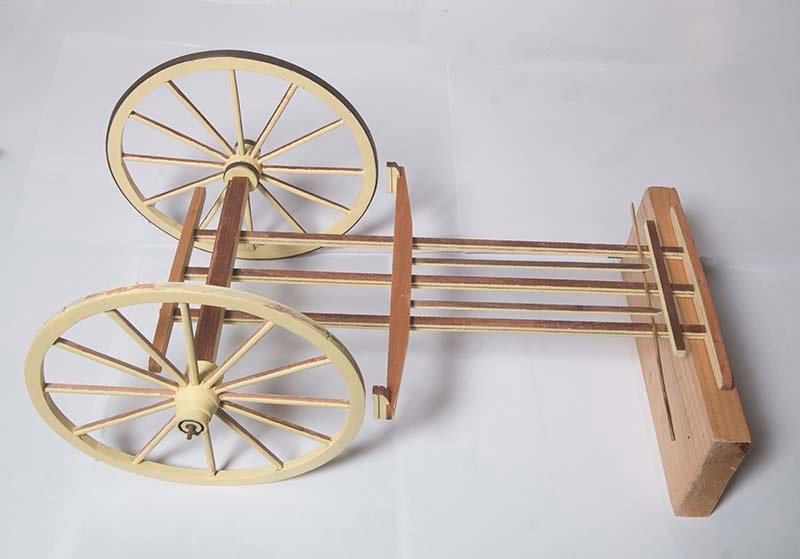
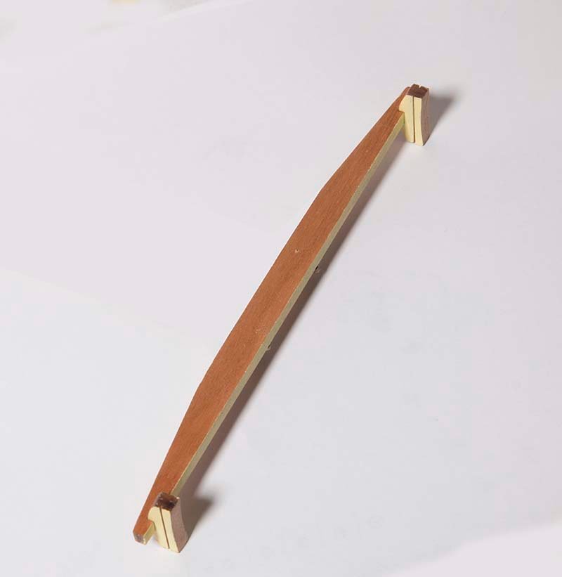
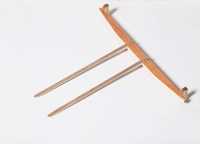
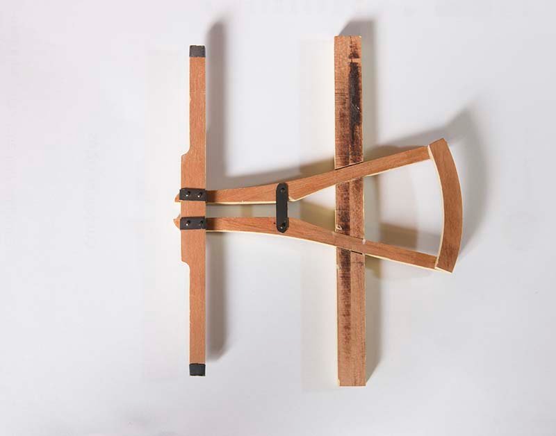
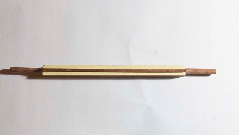
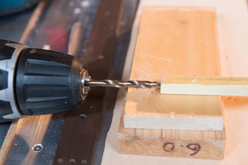
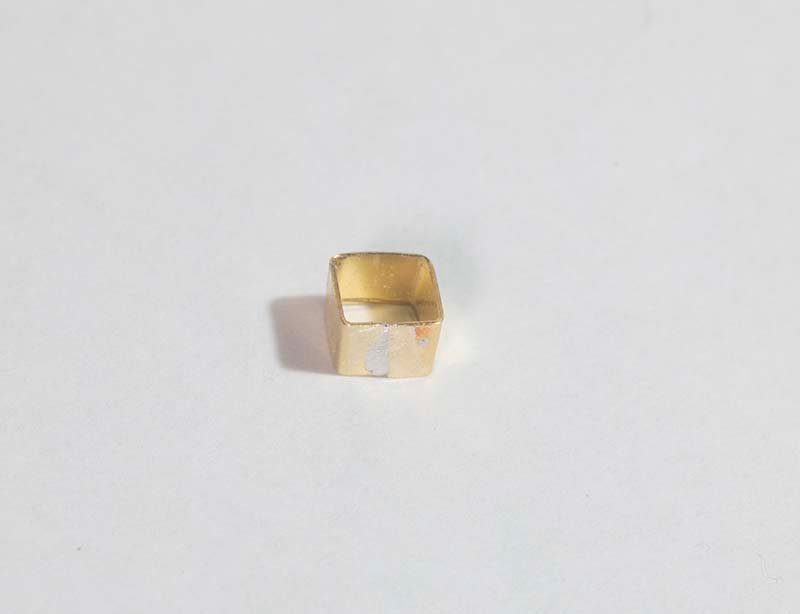
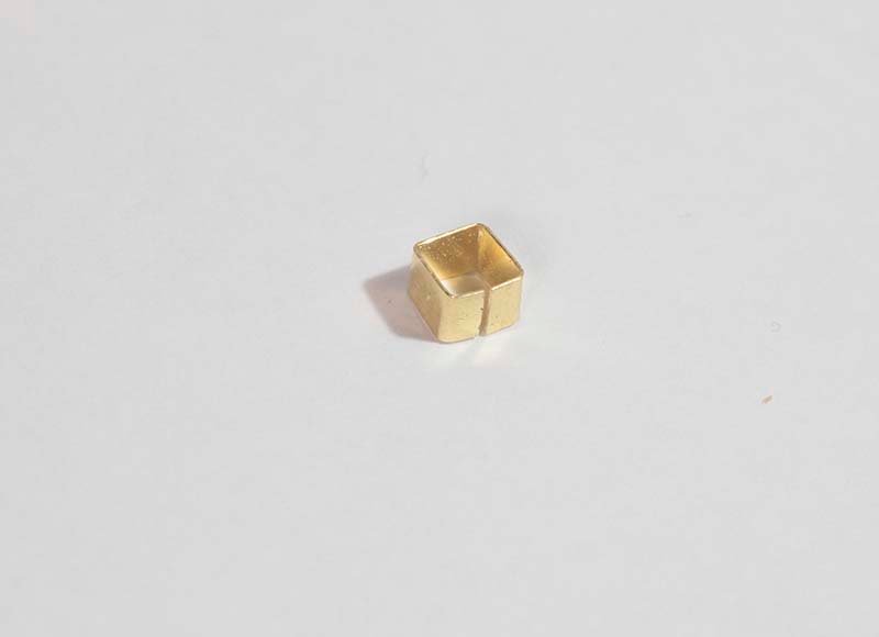
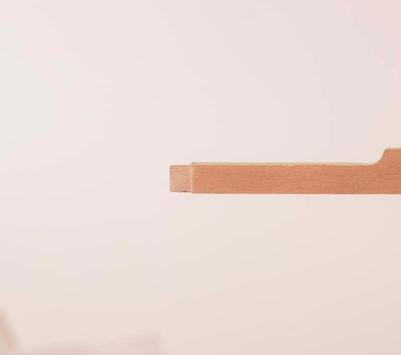
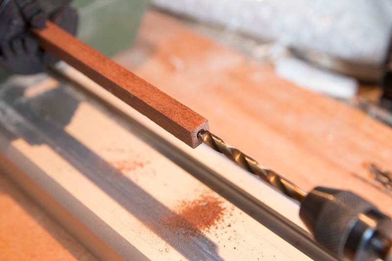
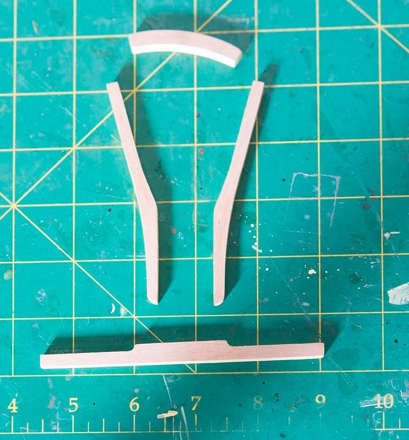
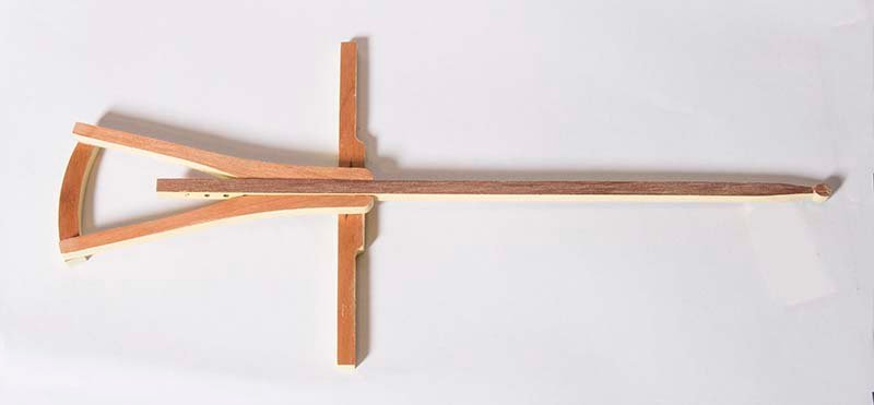
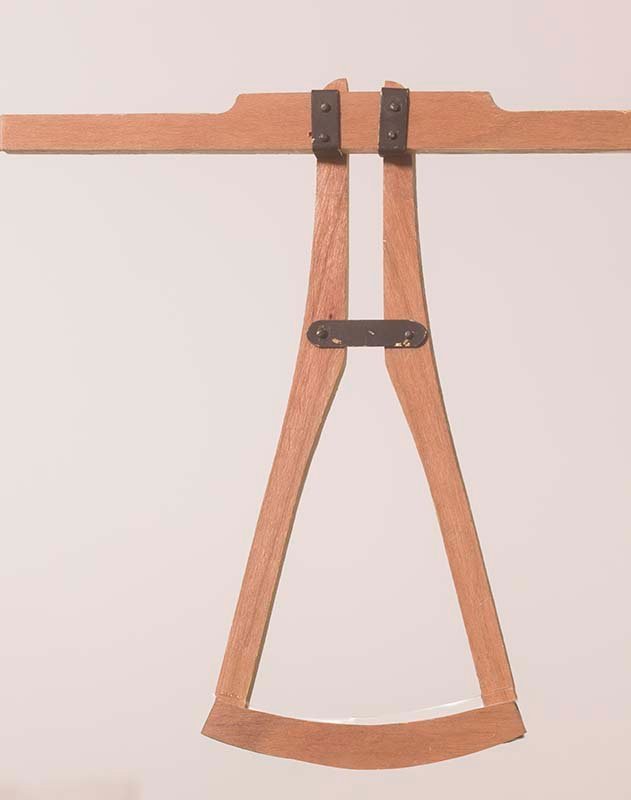
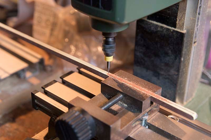
Steering Mechanism and Haul Bar This is quite a complex piece of woodwork and stars with four laser cut parts 5 mm deep, the curved steering bar, the haul bar and the steering struts: The Haul Bar is cut from 5 X 5 mm stock walnut and the end fashioned to a "knob" The parts are assembled in such a way that the haul bar moves freely between them: Ironwork was then added. In fact these clamps are actually brass, of course, but I don't think there would be much brass on these coaches so I chose to blacken them and then app;y a little weathering to make them look like iron. The side clamps are showm prode of the haul bar but I chose to inset them a litle The sqaew clamps were fashioned from 4mm brass strip and then the ends were silver soldered together: The final appearance of the unit is shown below Wheel Axels The real axel is made from 9 X 9 mm walnut stock and 5mm diameter holes need to be bored in the ends to take the stub axels The length was too long to fit under my mini drill press so the firs method I chose was to use my wood lathe. I have a 4 jaw chuck but it is not self centering and is difficult to set up. I thought I had it correct but with the length of the axel there was some precession and the hole hole turned out slightly conical. For the second axel I mounted my Dremel horizontally, chocked up the alxel and pushed it onto the drill. Surprisingly this made a near perfect perpendicular hole! In each case I stated at 1mm, then progressed in mm steps to 4mm, Here is the front axel: John
- 82 replies
-
- 13
-
-
-
Hi Bruce, Early days yet so it is a bit hard to comment on the quality of the kit. I think that the cabin will be the real test. However, so far it looks OK. The hubs are boxwood. The laser cut parts are walnut/boxwood and seem quite accurate. There is quite a lot of "scratch" work such as fabricating the spokes from dowel. This makes it a bit less like "painting by numbers" John
-
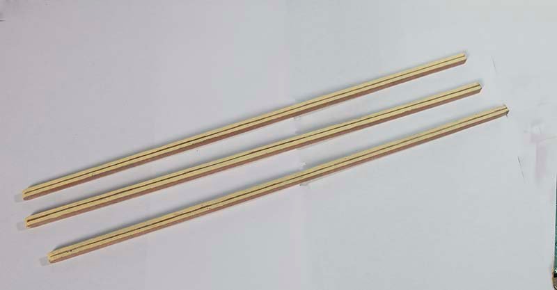
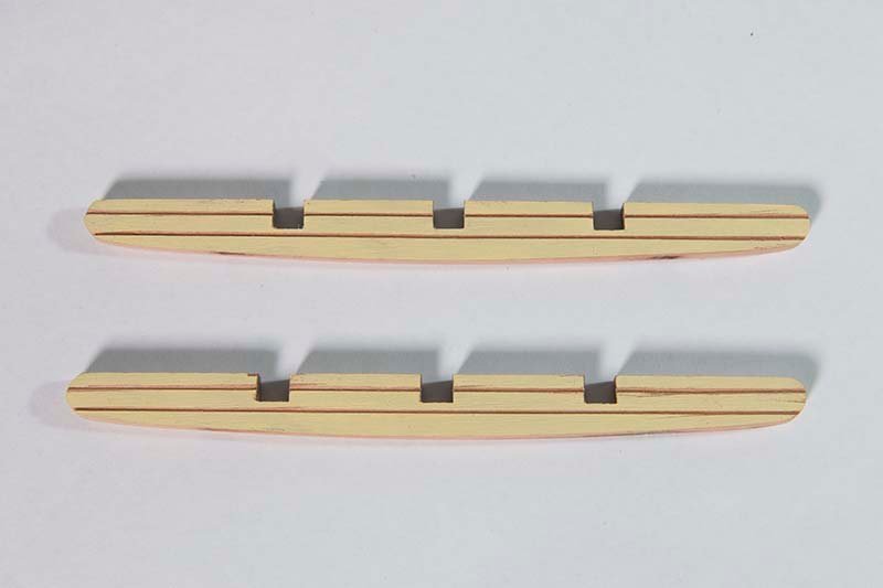
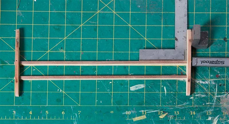
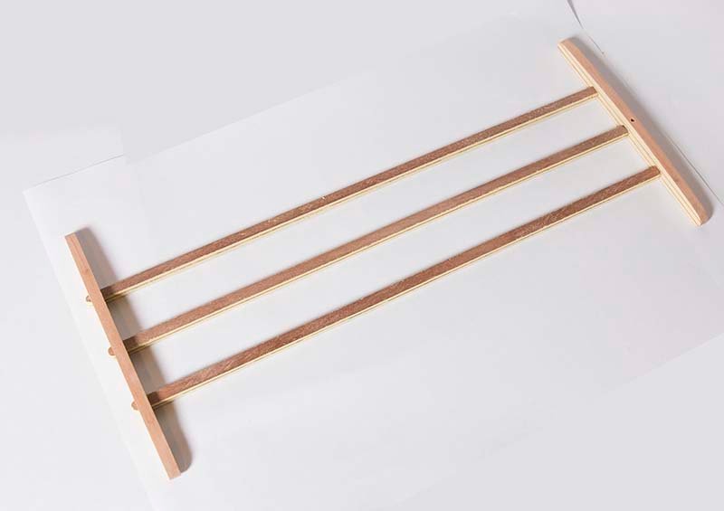
The Main Chassis This consists of three long beams connected to two suspension stabilizers. You will note that these both show "clefts" where presumably narrow planks where joined to make a wider board. These were produced using a mill and a 0.4 mm Kyocera end mill. After painting the two oposing edges, the beams were connected to the suspension stabilizers ensuring that everthing was at right angles: The final result looks like this John
- 82 replies
-
- 11
-
-
Thanks for the info, Bruce. It sounds like I will need to be careful with an expert watching on! John
-
Thanks for your interest Bruce, Yes, they are butt-jointed here on the model but on that historical wheel that I showed they are let in at the felloe end as well. In fact, on the model some of the but joints gave way and needed attention so it would not have been a viable system on a "real" wheel. At the Toowoomba museum in Queensland one can observe a wheelwright in action making a wagon wheel. First, all twelve spokes are driven into square holes in the hub. Then "pegs" are cut on the end of each spoke. Eight segments of the rim are made with holes bored at the correct distance. These are hammered onto the spokes. And it all locks together, NO GLUE!! John
-
Thanks Mark, There's a few finicky bits to do on those wheels yet but I am moving on for the moment. John
-
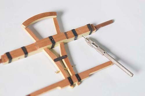
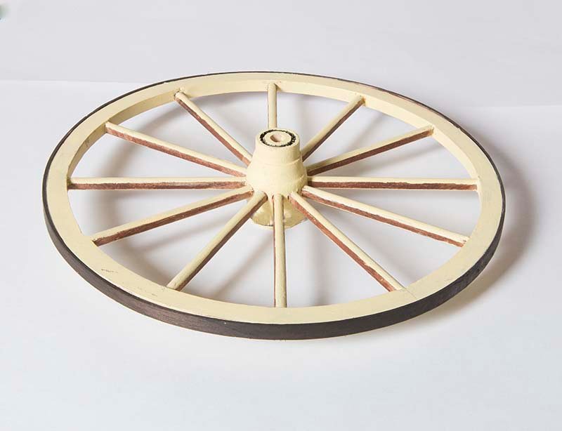
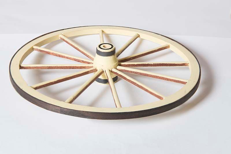
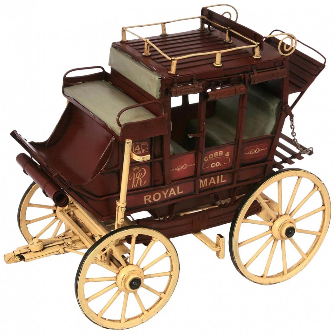
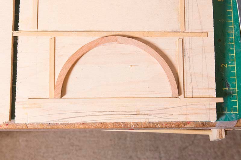
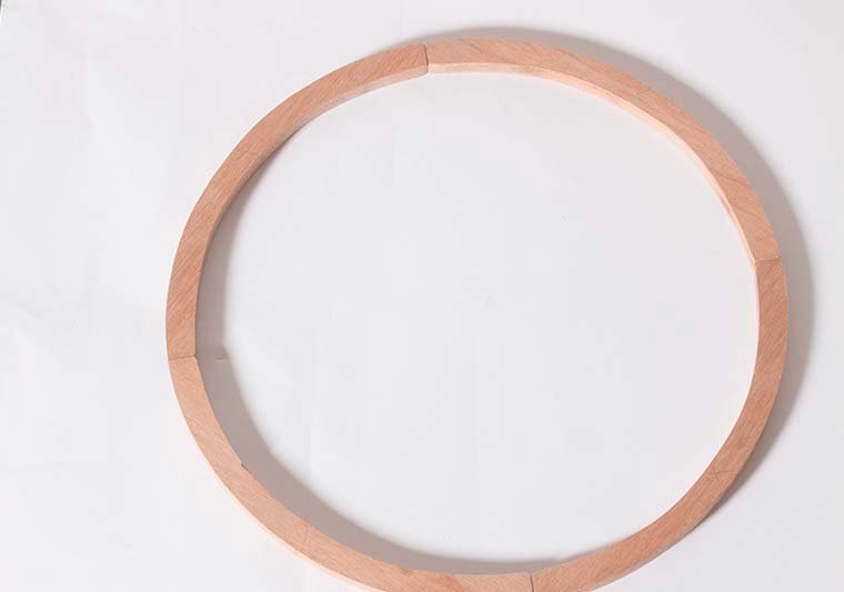
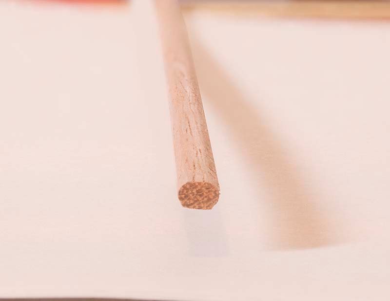
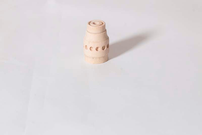
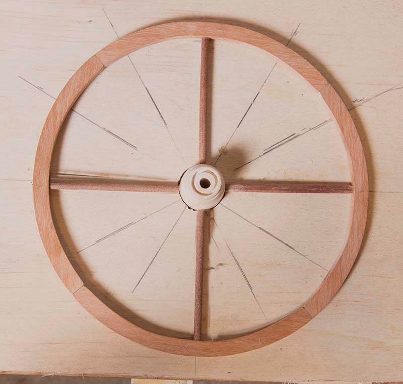
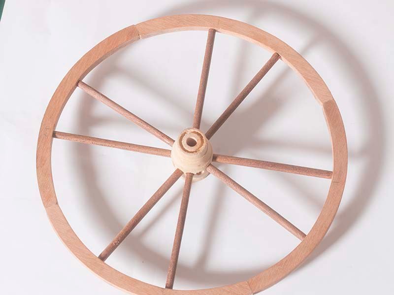
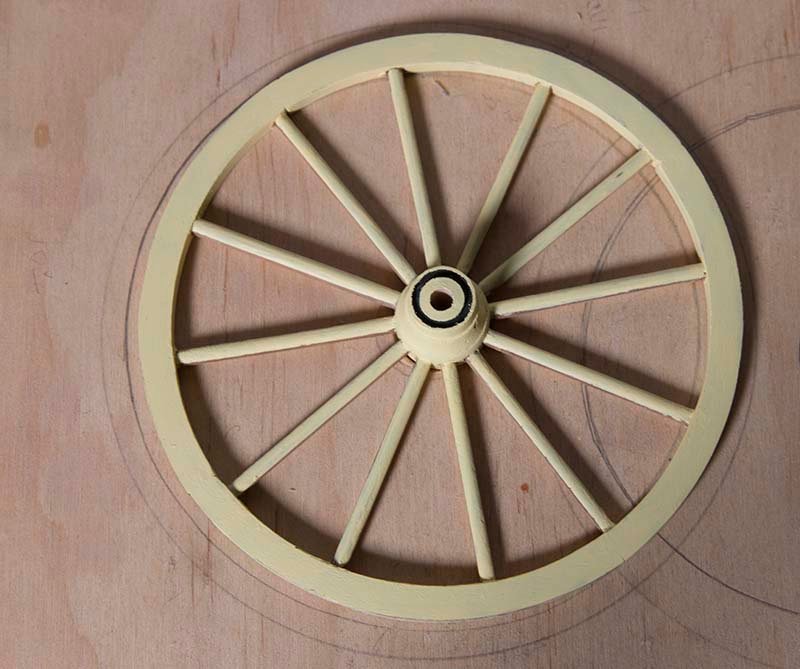
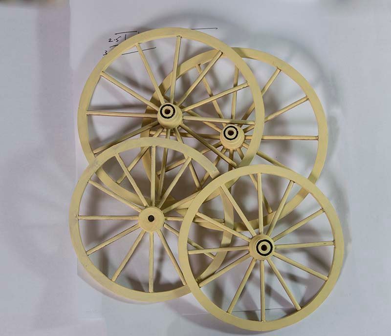
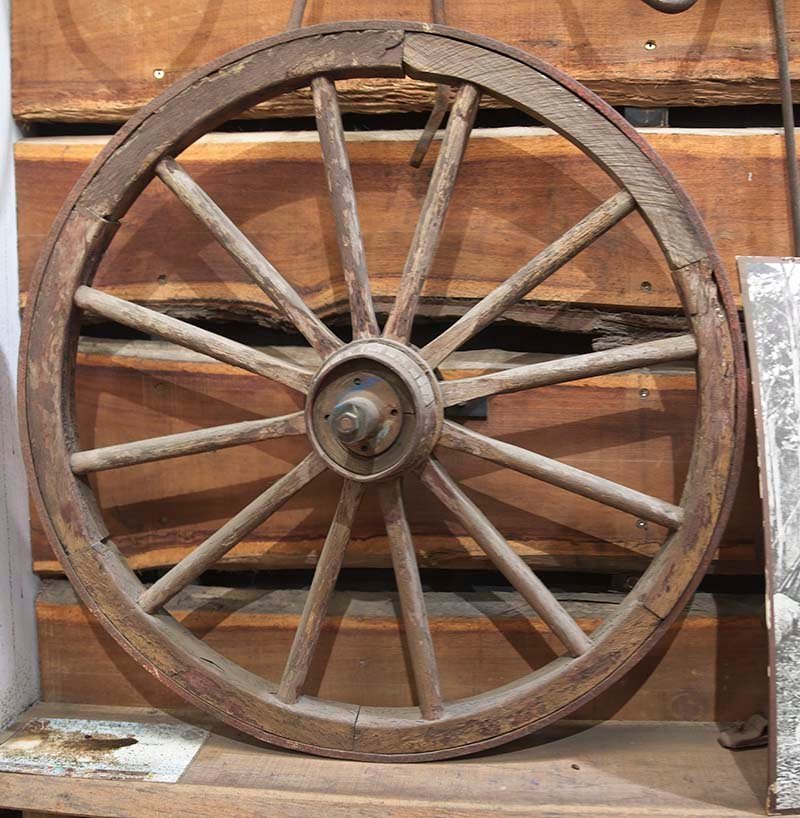
As an interlude from ship building I decided to build a Concord Stagecoach. These were originally made by Abbot Downing in Concord, New Hampshire were common through the American wet in the 1860’s but were also operated in Australia and New Zealand by Cobb & Co as mail coaches and also transport to the goldfields. This is a kit by Artesania Latina but will be bashed to achieve a more “Australian” look. This initially seemed to be a quick project but has turned out to be more complex than I first thought. The first task is to construct the wheels. Here is a wheel from about 1900 on display at my local timber merchant. It is probably from a bullock cart not a coach, but it gives an indiction of the mrthod of construction. These wheels have twelve spokes arranged around a rim, which in this case is constructed from four segments. In order to get these as perfectly round as possible I drew a circle of the appropriate diameter and then used the jig shown to make the two halves of the rim. The two halves were then glued together: The spokes are made from 4mm sapelly rod, which were sanded flat on two opposing sides to achieve a final thickness of 3 mm. The hub supplied was sanded smooth and the twelve holes bored at 30 0 to each other A simple jig was constructed to ensure that the spokes were evenly spaced. This consisting of a sheet of ply with a hole in the center to take the hub. the positions of the spokes were marked at the correct angles. Four spokes at rigt angles were added first. Then the rest added in a systematic manner The rims and the front and rearof the spokes were painted with Vallejo Model Colour #79.858. The inside edges of the spokes were left un-painted. And here are the four wheels completed:
- 82 replies
-
- 17
-


