
HOLIDAY DONATION DRIVE - SUPPORT MSW - DO YOUR PART TO KEEP THIS GREAT FORUM GOING! (Only 20 donations so far - C'mon guys!)
×


bartley
-
Posts
424 -
Joined
-
Last visited
Content Type
Profiles
Forums
Gallery
Events
Everything posted by bartley
-
You have deadwood above the last two bulkheads. This region should be thinned down but if this ship is double planked you might not want to plank in this region on the first planking otherwise the is region will end up two thick for the stern-post. You can estimate the width of this region with two planks on each side and compare that with the width of the stern-post
- 20 replies
-
- 2
-

-
- Planking
- Lining out
- (and 2 more)
-
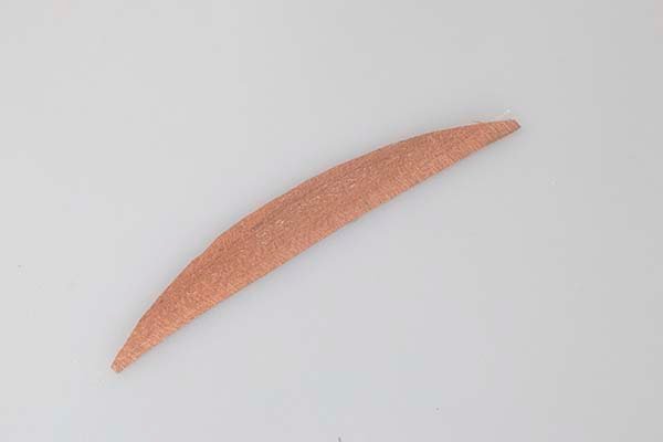
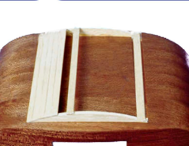
Construction of the roof The roof template is a shaped piece of 3mm basswood which is veneered on the inside with 0.6 mm mahogany The top side is covered with 1.5 X3 mm walnut strip and 0.6 X 2mm basswood in alternate rows. This arrangement presumably provided some traction for moving about on the roof. In fact in some cases extra passengeerd rode on the roof top: Finally the roof is attached to the cabin John
- 82 replies
-
- 11
-
-

-
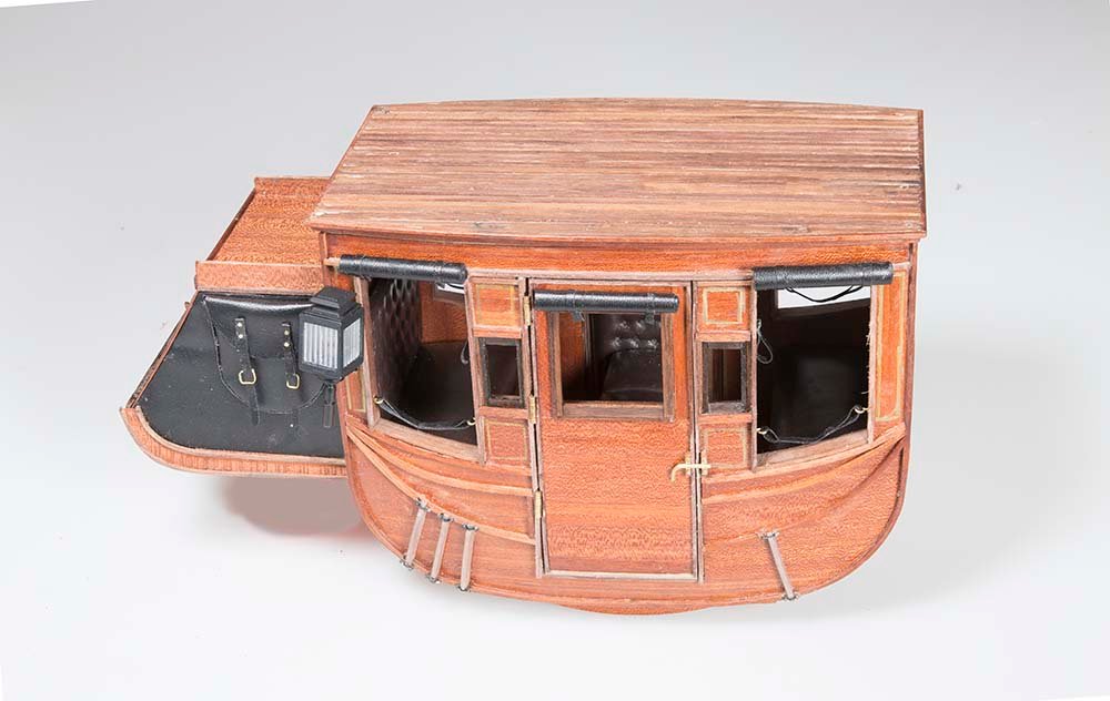
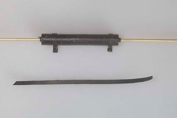
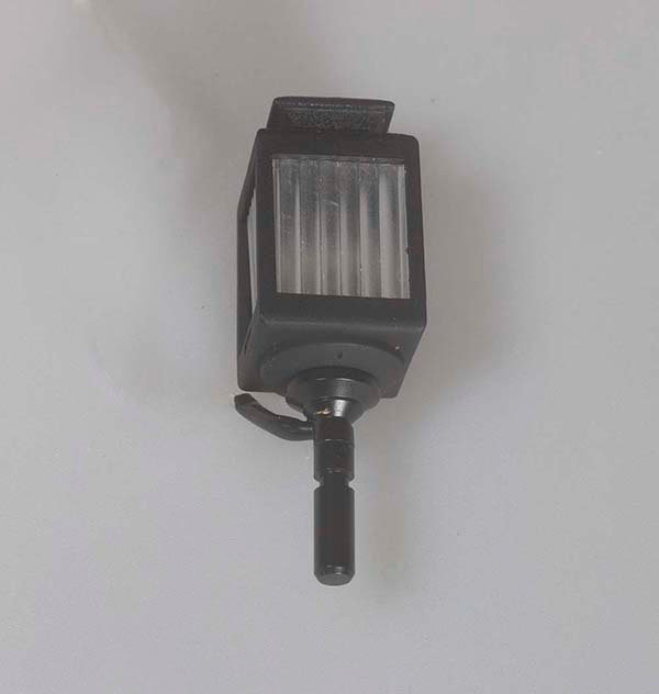
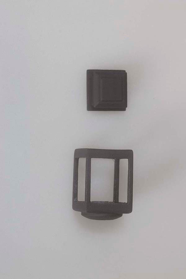
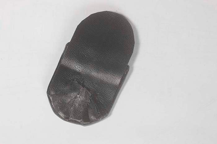
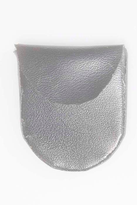
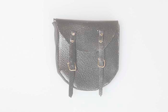
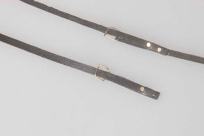
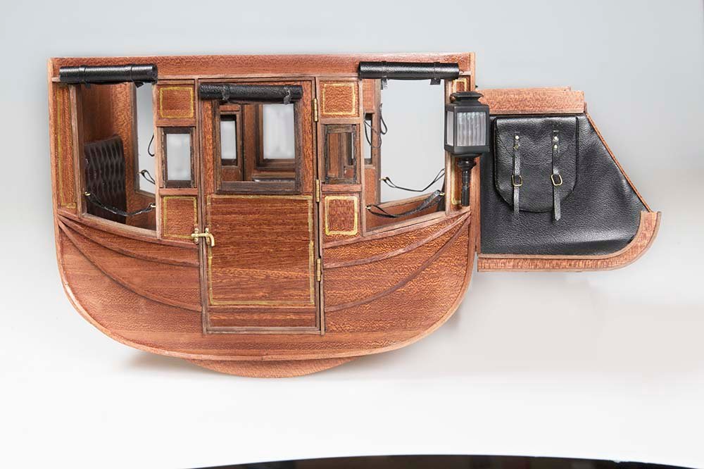
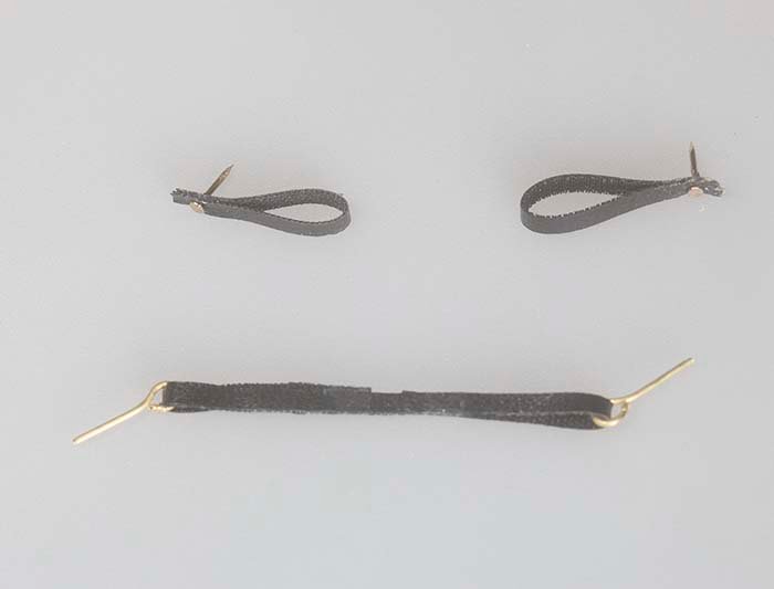
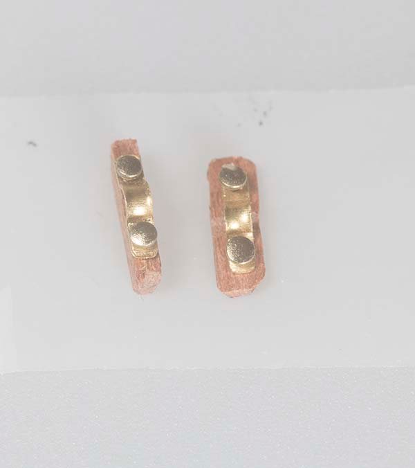
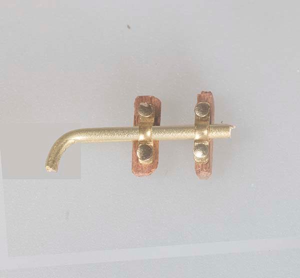
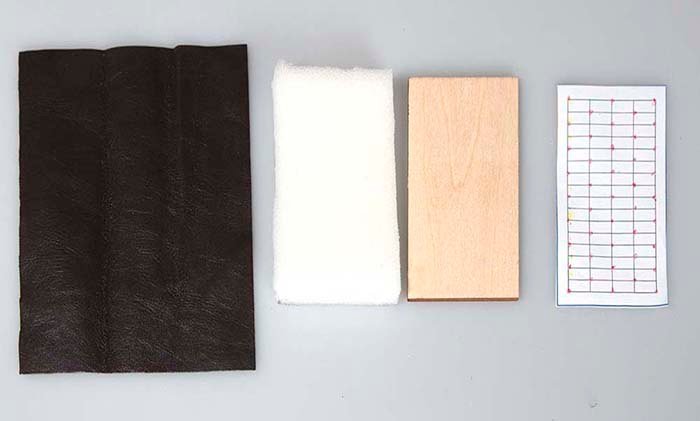
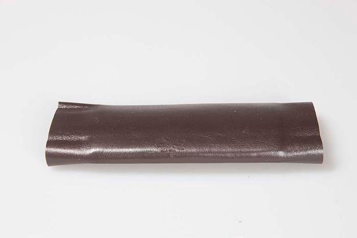
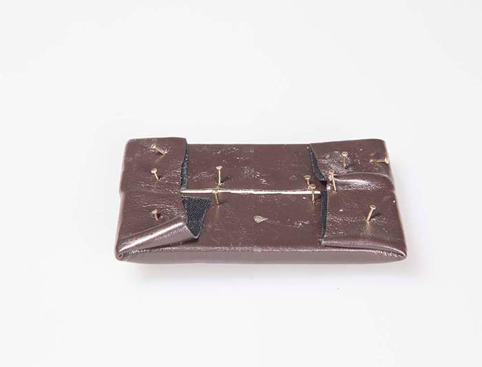
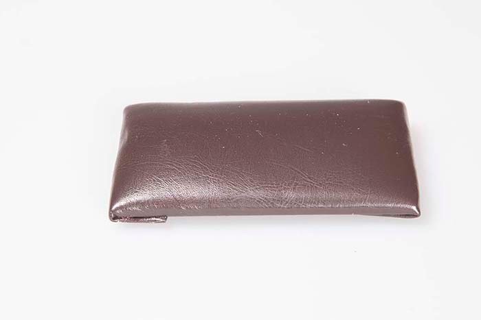
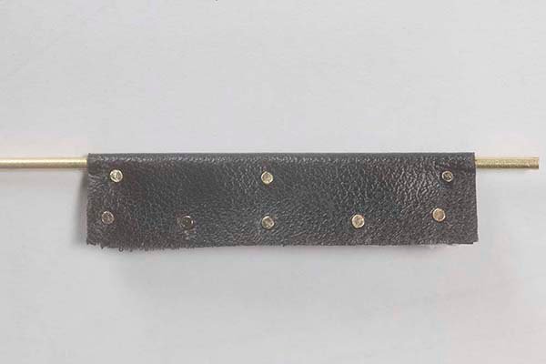
A few more Details - A bit of shade and a bit of light 1. Blinds These are made by stating with a 45 x 90 mm sheet of artificial leather these are then rolled up around a brass rod and secured with 2mm strips of the same material 2. securing the doors The door bolts are fabricated by first mounting small saddles on a block of walnut, securing them to the sides and then sliding a small piee of brass rod through them. 3. Lamps for traveling at night lamps are made in two parts and then the small windows supplied are glued inside 4. Mailbags Companies such as Wells - Fargo in America and Cobb and Co. in Australia negotiated quite lucrative contracts to deliver mail. In fact this this led to a considerable improvement in the turn around time for mail delivery. The two mailbags are made by wrapping the artificial leather around a brass frame The straps are made from 2 mm strips of the same materials and buckles are simulated with small brass rod It was a rough ride in these coaches in spite of what the operators claimed some some hand holds were provided: Once all of these items are attached the cabin now looks like this: Once I am satisfied that the interior is complete it will be time to attach the roof. John
- 82 replies
-
- 14
-
-
-
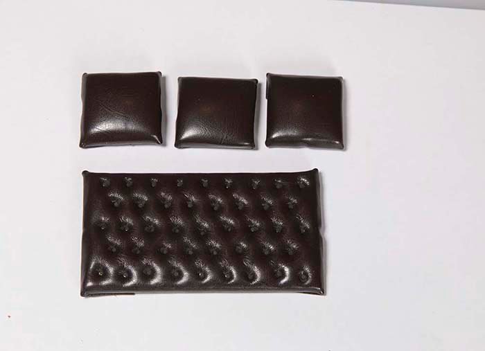
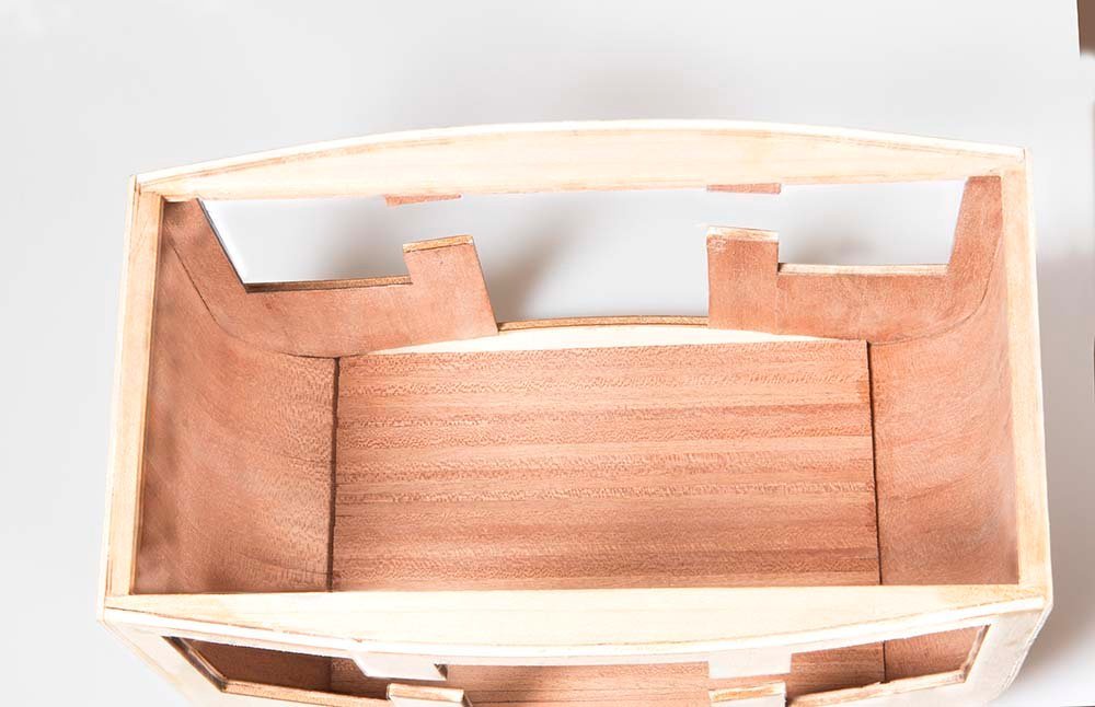
Seating arrangements The seats and the backrests are upholstered in the usual way. Foam fillers are glued to a ply backing board of the appropriate size. Brown artificial leather is then folded over this arrangement and glued to the ply backboard. The seats themselves are left plain and the backrests are buttoned in a similar way to the door padding. These main seats are mounted on a bracket attached to the interior side wall and the back rests were glued to the front and back interior walls. The support for the middle row of seats is made from a flat platform and six supports. These are veneered on both sides with sapelly sheeting: The padding for the three seats in the middle row are made in a similar way to the above. These were in fact removable but I have glued mine in to stop them moving about. Here is a shot of the completed interior: John
.jpg.34ad3f0b220a9d18b1b3584a07a15ede.jpg)
.jpg.785ab52bd0c46431b04397d2d71537ba.jpg)
- 82 replies
-
- 12
-
-
-
Handrails for Coachman's Box These are made from 2 mm brass rod. The parts making up the rails were soldered together with silver solder. I made a simple jig to make sure that the handrails on each side were identical as near as possible. r: The padding for the side armrests was made from black nappa cloth The rails were painted black and then treated with weathering powder to make them look more like metal. This effect is quite subtle and might to show well in the photograph. However I think it is effective. the top rail is just black paint and the bottom one is weathered The padding is slipped over the middle rail and the final effect is shown below: These will now be attached to the roof of the box along with the seats for the coachman. John
- 82 replies
-
- 11
-
-
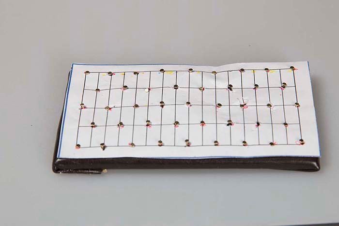
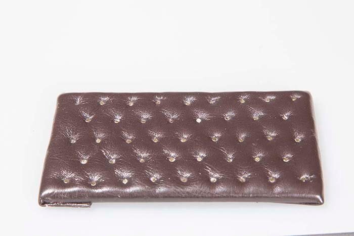
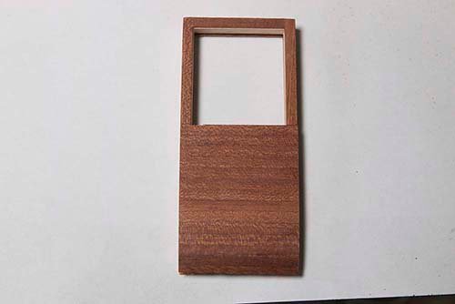
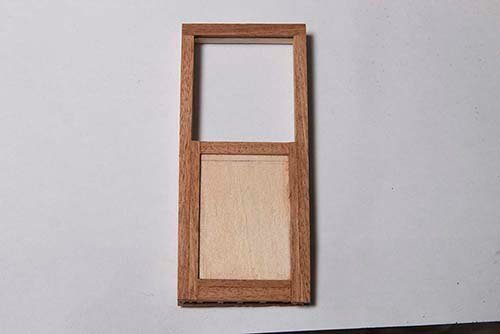
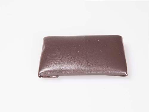
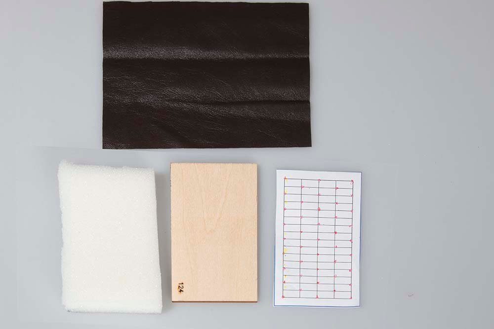
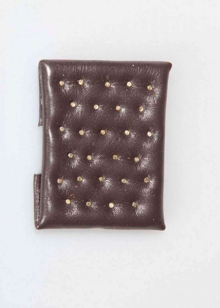
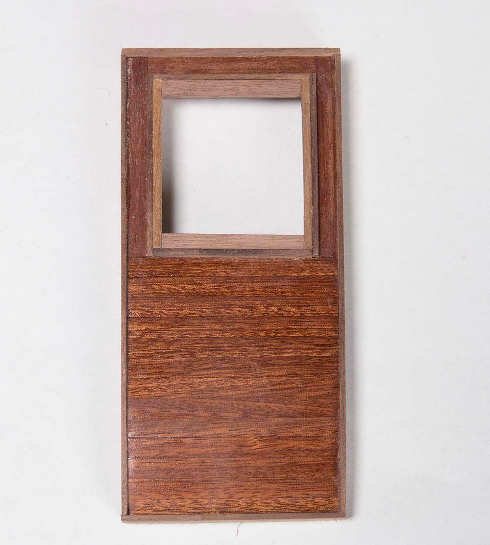
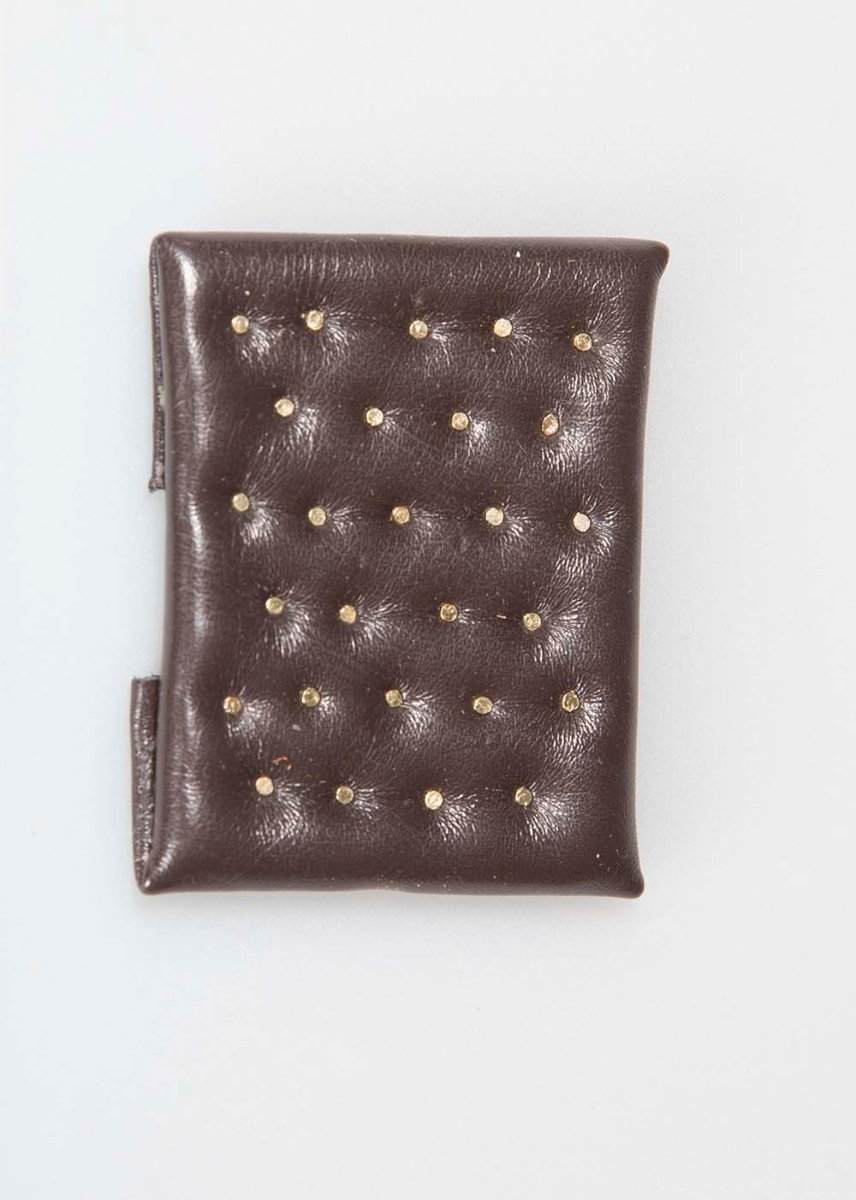
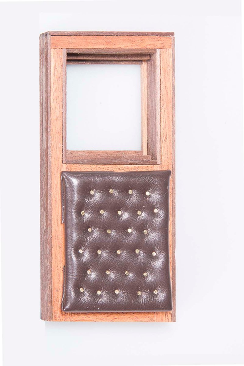
Cabin Doors These are constructed in much the same way as the cabin itself. First, 2X 5 mm basswood battens are laid down and sanded to fit the shape of the cabin. Then 1 X 5 mm Sapelly planks are glued to the outward facing side and a simpler set of plank to the internal side: Window frames and side frames are then added once again in a similar way to the cabin itself, starting with 1.5 X 12mm walnut strip: The padding for the inside of the door Involves first gluing foam pieces to board and then upholstering this with brown nappa cloth. A buttoned effect can then be created by nailing a paper pattern to the upholstered surface: The final effect looks like this: This is then glued to the inside of the door: The doors turned out to be quite a tight fit into the cabin and quite a bit of sanding was required so that hey could move more freely John


- 82 replies
-
- 10
-
-
Yes, Javlin, It is Sapelly which is a poor man's mahogany. Most panels are veneered over bass wood ply. I looked at buying Mahogany or Sapelly panels but they are hard to come by and expensive. I am coating with several coats of Danish Oil sanding back with 600 grit in between coats. Regards, John
-
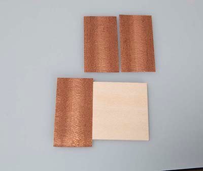
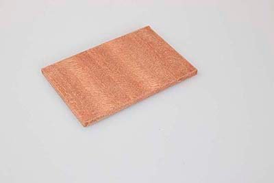
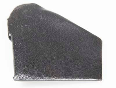
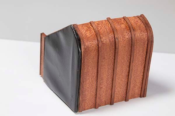
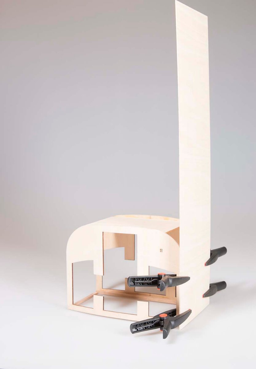
Coachman's Seat and Box: For some reason this is translated in the instructions as "winch"! Strictly speaking I should be constructing the doors next but I am waiting for some more timber for these so I decided to start on this coachman's box. This is quite an elaborate unit. It starts with two curved panels, a bottom and a back piece: The panels are veneered on both sides with 0.6 X 30 mm Mahogany: The initial assembly after veneering looks like this: The curved bottom is also veneered: two internal and two external panels are then covered with black napa and then attached to the sides of the box: Sternthening battens made from 1.5 X 3 mm mahogany are attached to the curved bottom: two side pieces are then constructed from veneered panels with 3 X 1.5 mm walnut capping pieces: After attaching these and constructing a foot board from 1.5 X 3 mm mahogany strip, the box at this stage looks like this: There is more to do on this unit but this will be attended to in the next sesion. John
.jpg.ebb011564e55640b3035e38ebf630fe5.jpg)
.jpg.bc8b2549f08359855c77a0f8a935d4d9.jpg)
- 82 replies
-
- 12
-
-
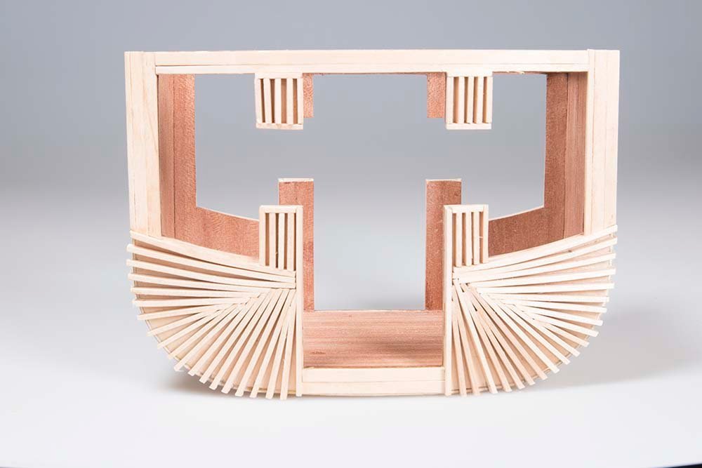
Cabin Decorations and Window Molding The cabin decorations are curved embellishments made from 2 X 2 mm mahogany strip. These were bent using a similar process to that for the cabin edging in the previous post. They were shaped to fit and then glued to the cabin walls with CA. The window molding (referred to in the instructions as moulds!) is simply an extra 1.5 X 1.5 mm strip glued on top of the original window frames. I guess this does give a crisper edge. It seems to make the frames protrude a long way but it would only be 25 mm at full scale so it is probably about right. Here is the final result: John
- 82 replies
-
- 14
-
-
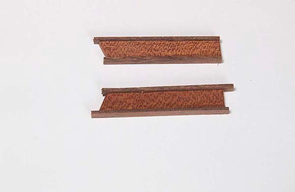
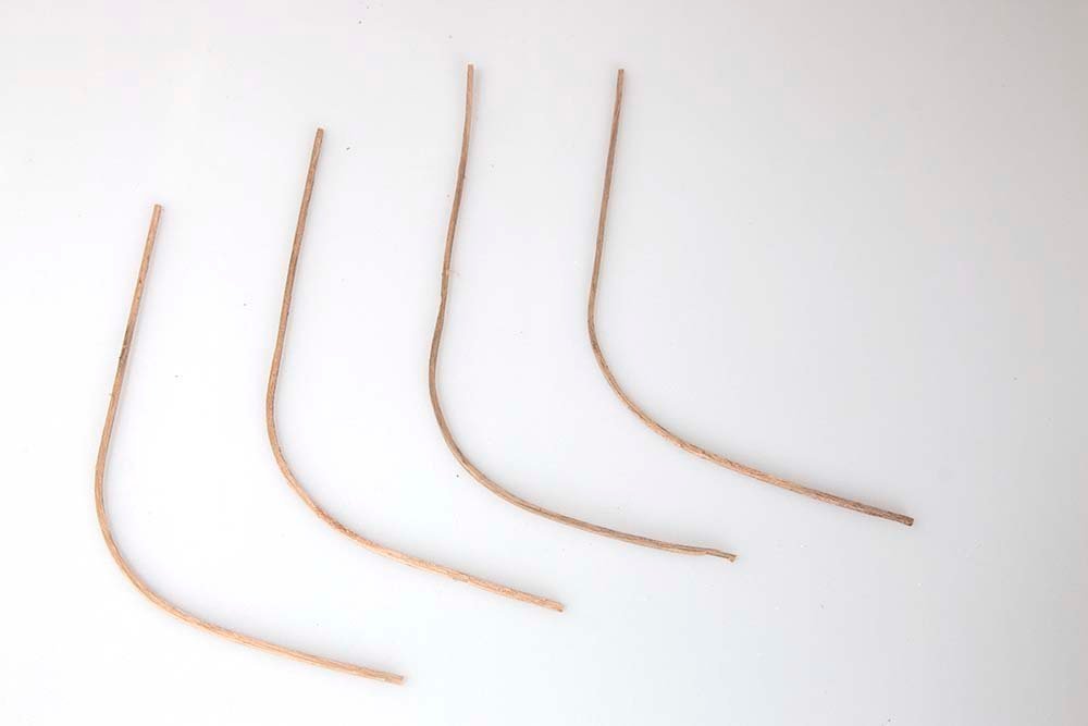
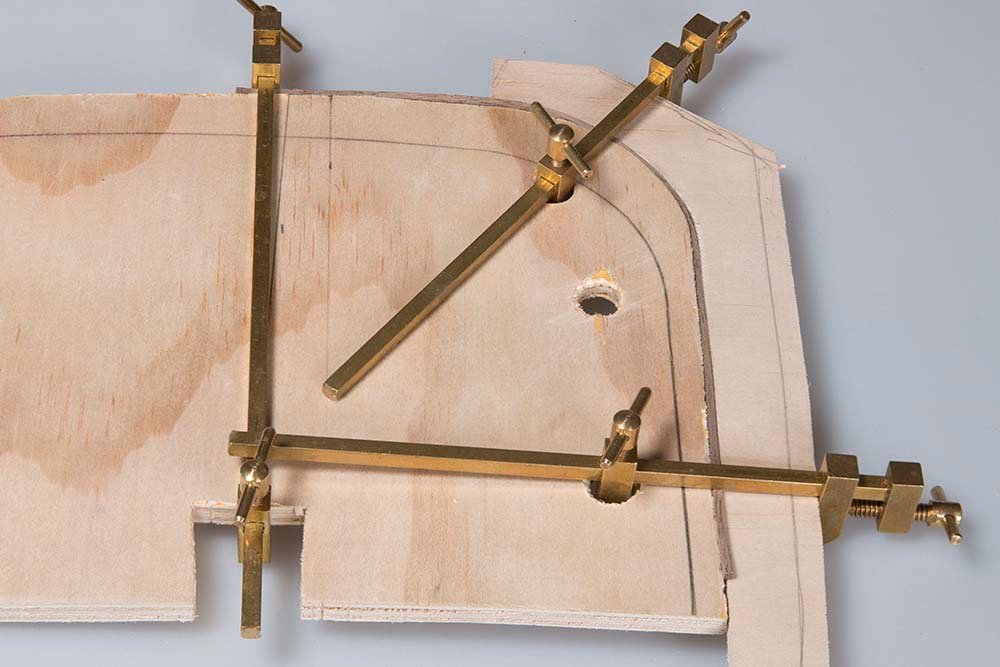
Window Frames and Cabin Edgings: The windows are framed with 1.5 mm thick walnut strip between 8 mm and 10 mm wide depending on the depth of the window from the curved front and back of the cabin. This quite straightforward and gave a nice crisp edging to the windows and covered the boxwood ply edge of the cabin. These frames were flush on the inside but allowed to protrude about 1mm on the external side sanding back where necessary in order to achieve this. And the completed window frames: The edging to the cabin involves bending 2 X 2 mm Mahogany strip to fit the shape of the cabin. This is quite a sever right-angled bend and previous experience with mahogany is that it is quite brittle compared with other timbers such as Alaskan yellow cedar and basswood for example. First I constructed a jig to establish the appropriate curve. Then I heated the Mahogany strip in boiling water for about 10 min Then bent around the jig using a heat gun in order to achieve this. Once four pieces had been bent they were glued to the edges of the cabin using CA (two on each side with a join at the center). Next some decorative features. John
.jpg.65ca19107ebe5ee600bbe21e3970ff8f.jpg)
- 82 replies
-
- 12
-
-
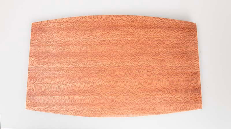
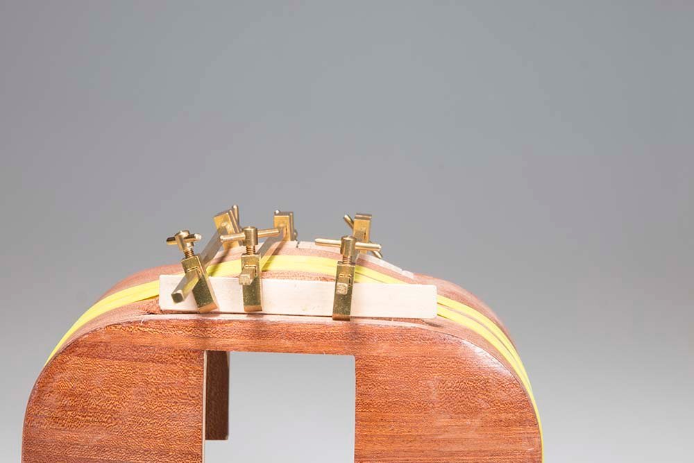
Lining the Exterior Curved Wall The exterior curved wall is now lined with the same 30X0.6 mm Mahogany veneer that was used on the interior. this ids quite straight forward really. started at the middle and drew a center line and another 15 mm eqch side. It was clearly important that this first sheet was correctly aligned and centered since all the alignment of the other sheets will depend on it. I painted PVA glue onto the sheet clamped each the sheet each end: To make sure that the curved part was tight against the frame by rubbing it with a flat piece of waste timber, I finally "clamped" the sheet with a couple of large rubber bands: I find these useful for a job like this which is difficult to clamp with conventional clamps. Each subsequent sheet was buttted tightly against the previous one and secured in the same way. After trimming off the excess the rsult looked like this: The next task is to construct the dome shaped double bottom which sits on the suspension straps. The instructions would have you glue the two curved formers to the cabin bottom first and then plank over these with 5X1.5 mm strips. I felt that it might be difficult to align these both parallel and square, so I decided to construct the initial "box" shape off the model: The curved former pieces are on the right and left and the first planks above and below. Incidentally, these former pieces have to curve on both sides side since the bottom itself is curved and a tight fit is required so that the glue will form a strong bond. This frame was then fitted between two parallel guides clamped the the bottom at an equal distance from each side: This unit is then fully planked over with 5 X 1.5 basswood planks to form a base for the veneer. After the veneer was applied to the frame in the usual way, two small endpieces were made to cover the formers.. These were clamped while the glue dried: And the completed unit after sanding back and one coat of finish: So finally all the veneering is complete. Quite time consuming task but now I can move on to lining the windows and doors. John
.jpg.0ed60086a17ff23cdeaafd16c8d5eb5b.jpg)
.jpg.a9772d7bce4c4bd9f5de97ac9b15a943.jpg)
.jpg.8e006e95337dd504dd1076c946f5c720.jpg)
.jpg.29a3e217caad5405c332d443b63f1f95.jpg)
.jpg.5074586d47c301434449110f220257ef.jpg)
- 82 replies
-
- 13
-
-
-
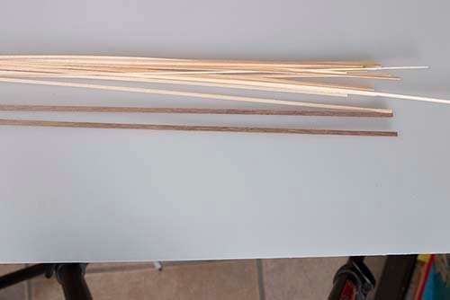
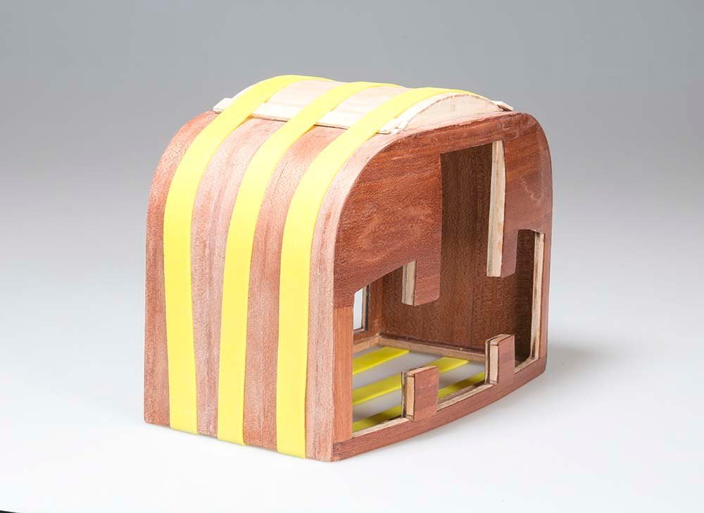
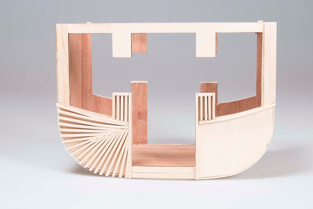
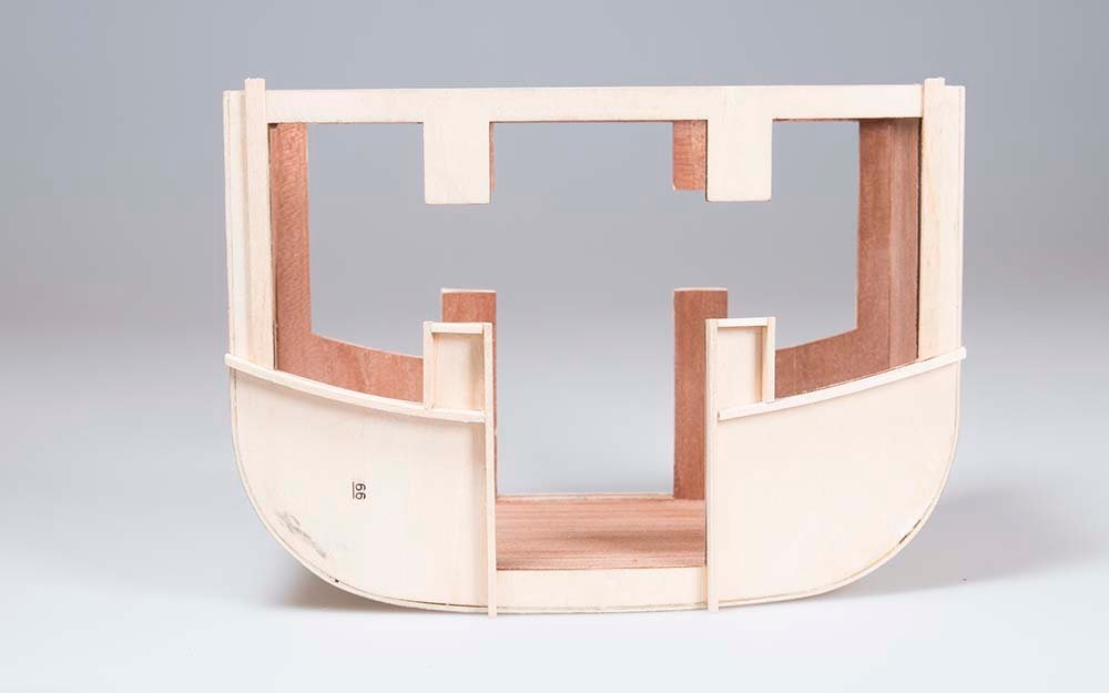
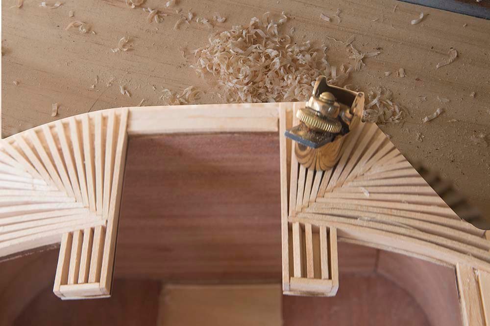
Planking the Front Firstly , in order to ensure that the first plank on each side was in the same position and perfectly horizontal, I clamped a registration guide along the front: Then planking began in the standard way using 5X1 mm mahogany strips: It was only on the second side that it dawned on me that just as on ship planking a slight bevel to each plank helps to achieve a tighter and neater result! So after planking was complete each side was sanded back using these sanding sticks: I went down to 600 to achieve this result: Then after a couple of finishing coats with alight sanding between each the final result looked like this: The next task is to plank the curved sides and bottom. Cheers, John

- 82 replies
-
- 13
-
-
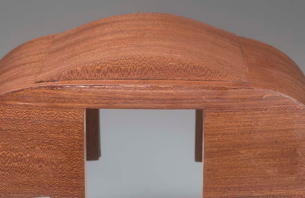
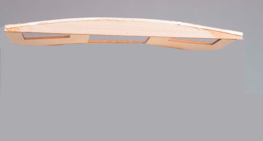
Preparing the Front Panels for Planking This is an interesting process. In order to produce a concave or domed contour on the front and back of the cabin both surfaces are covered in 5 mm battens. These are much like the ribs on a ship and are eventually faired to produce the curved shape to support the planking.Some of the steps are shown below: Battening around widows and doors: Horizontal battens on the top and sides of the front panel Full battening of the left side of the front panel The completed battening: The instructions suggest fairing the battens with course sand paper. I started the process with a small Luthier's plane and finished off with sandpaper: The completed fairing job is hard to photograph. In the photo below you can see the general effect but the perspective makes it looks as if there are bumps and hollows. In fact the curve goes very smoothly from about 5mm near the top of the door to virtually zero at the outside edges. The horizontal planking which comes next will accentuated the domed shape. By the way thanks for all the "likes" it is very encouraging. John
- 82 replies
-
- 13
-
-
-
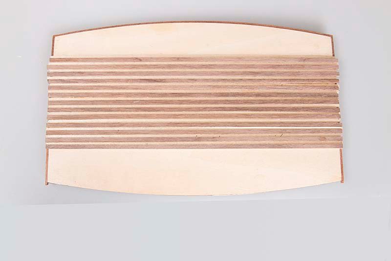
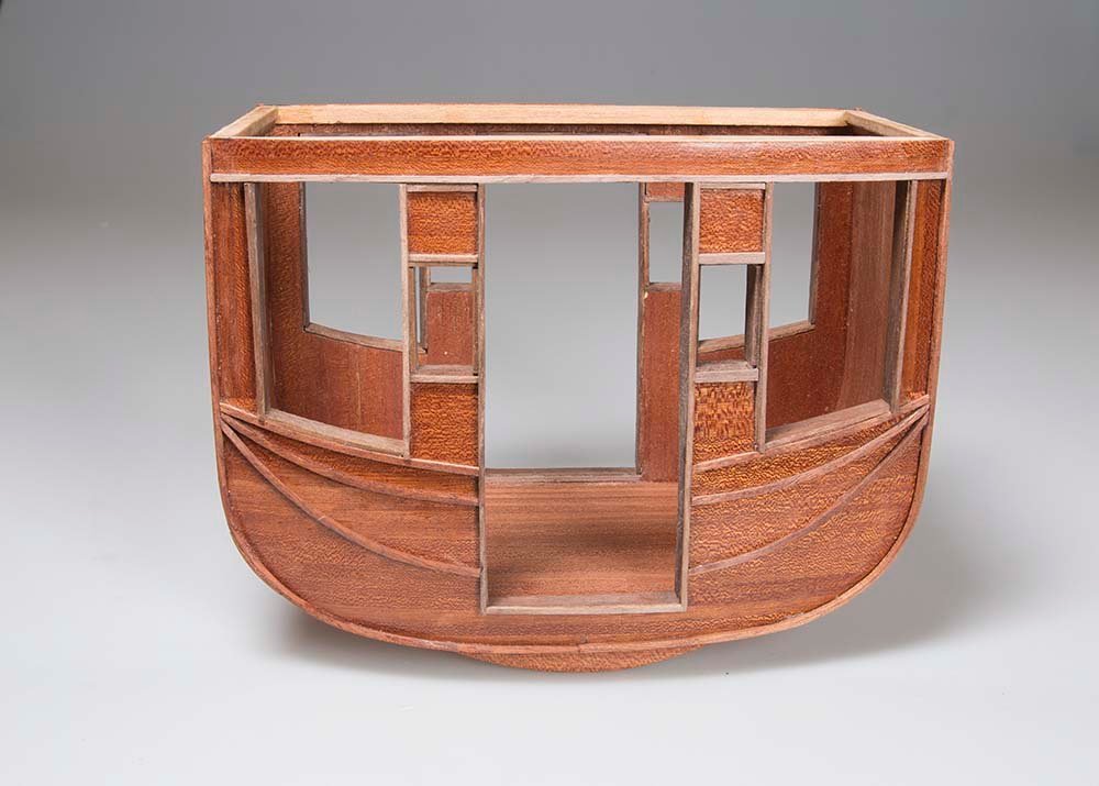
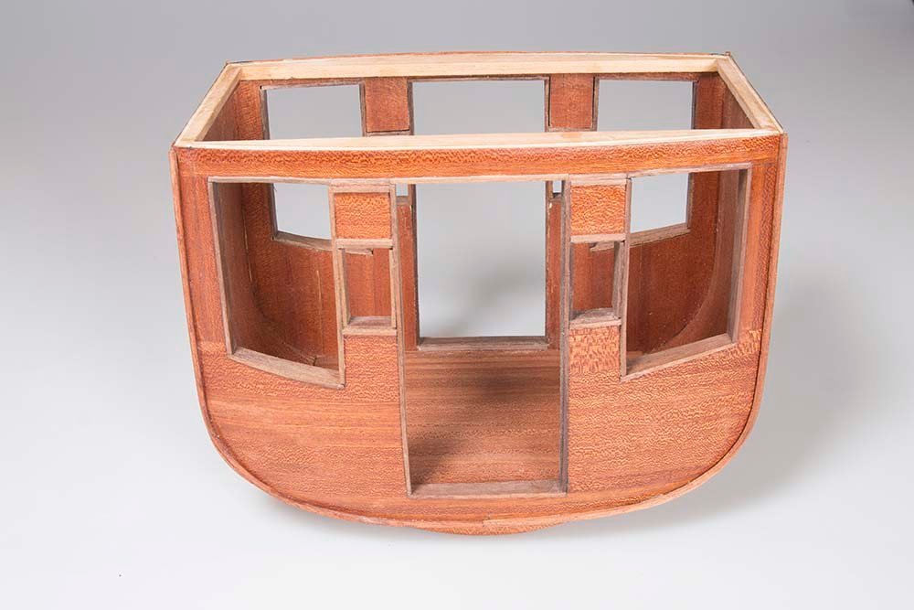
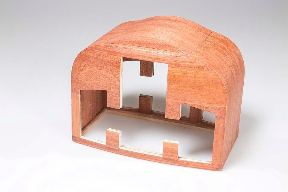
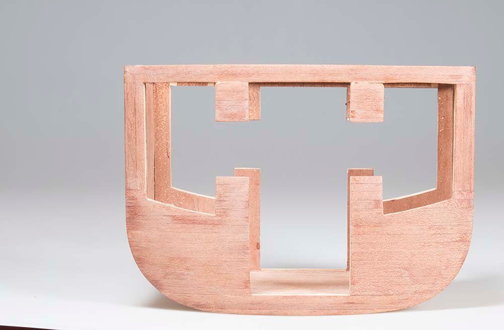
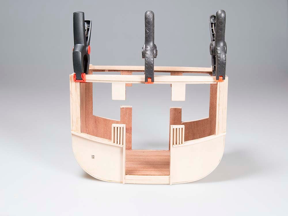
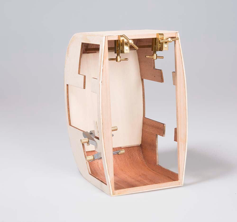
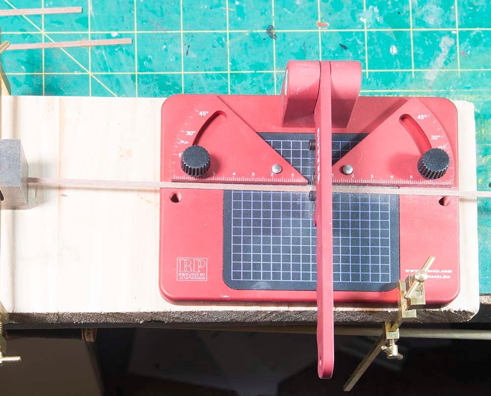
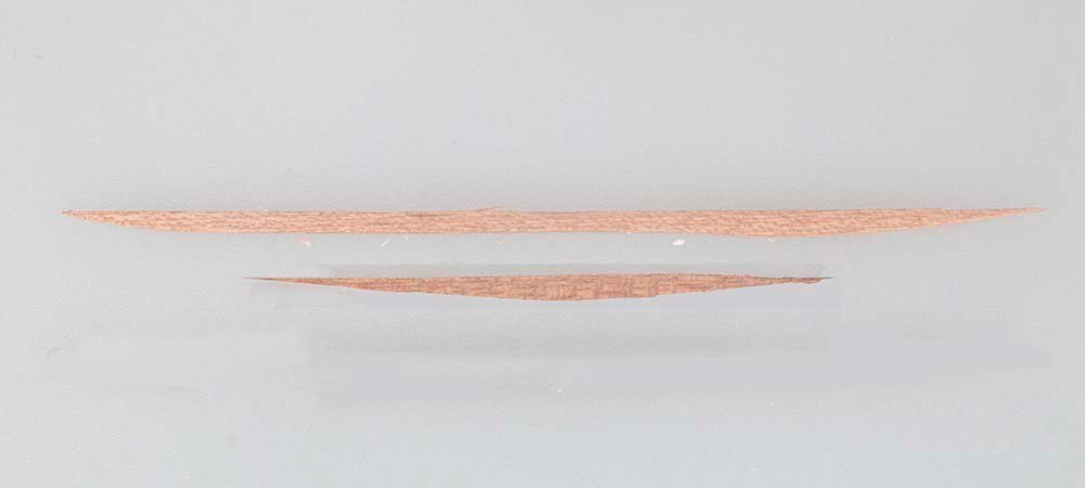
Lining the Interior The interior of the cabin is lined with 30 X 0.6 mm mahogany veneer. This turned out to be trickier than it seemed. There are some difficult angles. So I made some card templates like these: So here is the first sheet installed: Petty well complete mow - as is often said "you can never have too many clamps" The floor is planked with 1X3 mm mahogany much like the deck of deck of a ship but much simpler - no bow or stern to allow for! I cut these planks accurately to length using a jig attached to my RP cutter - I have had a few versions of these cutter but this is the best so far - all metal construction and gives very reproducible results: Just a couple of curved planks to go behind the doors: and so the completed interior looks like this: Now to the exterior planking. John
.jpg.56cc6da8e01d87948a0b78851dbca865.jpg)
- 82 replies
-
- 15
-
-
Don't know about that one Kev! There are a few mistakes that I am not admitting to! John
-
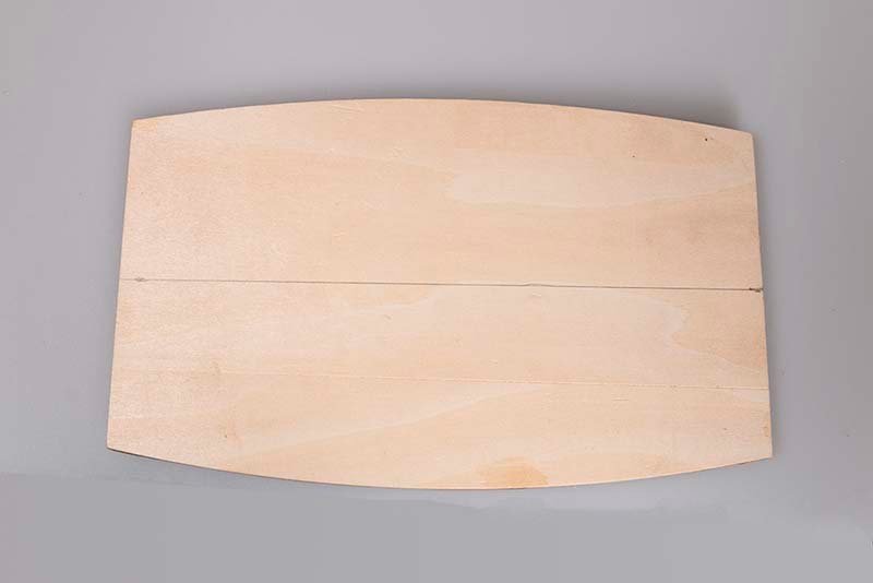
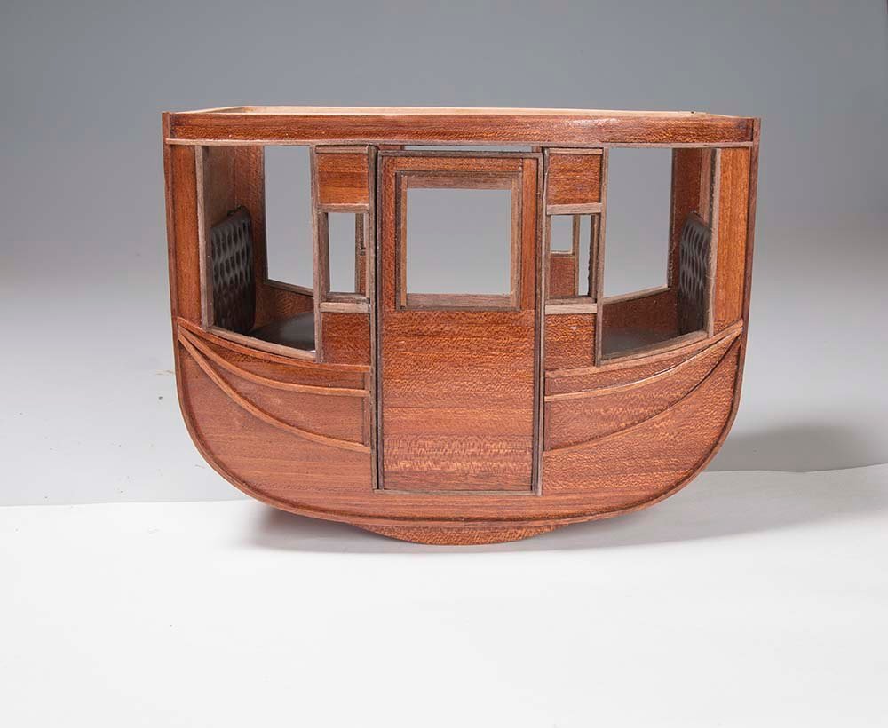
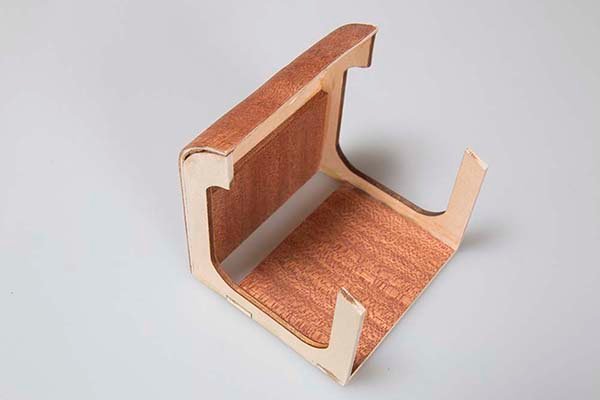
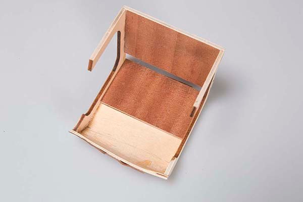
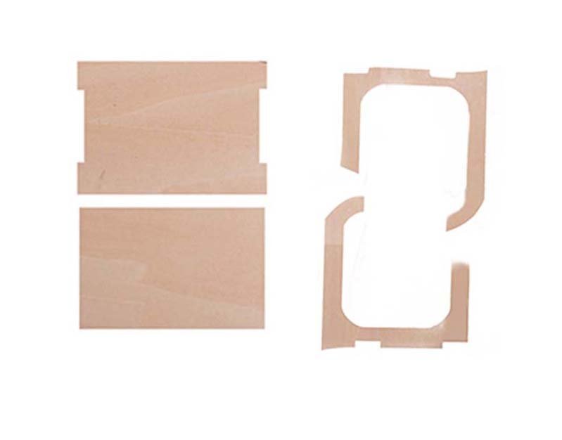
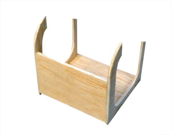
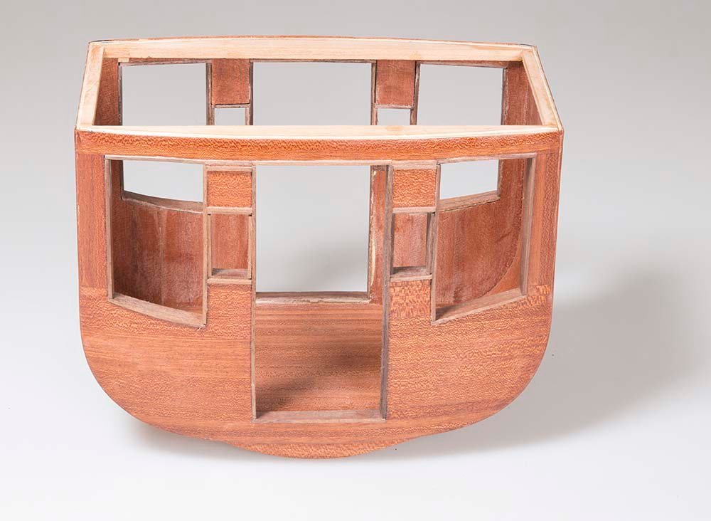
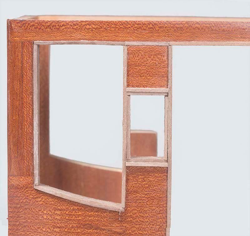
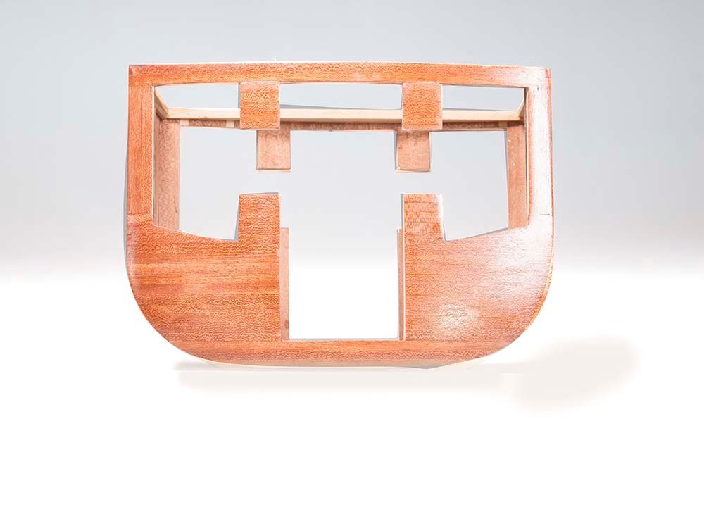
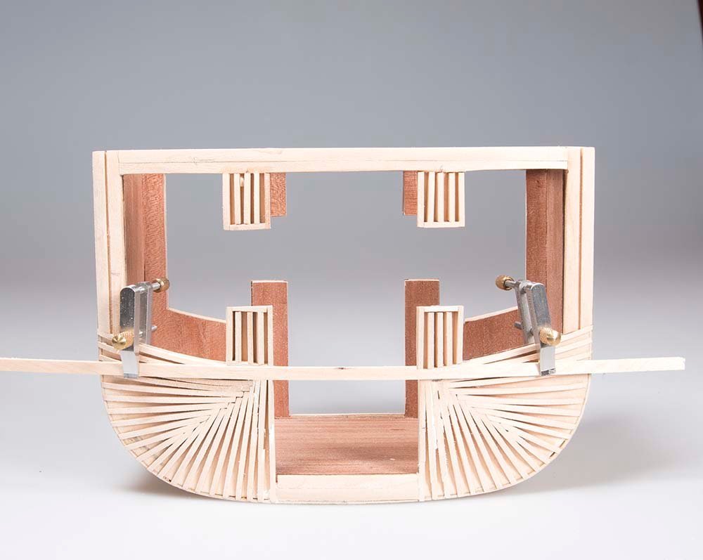
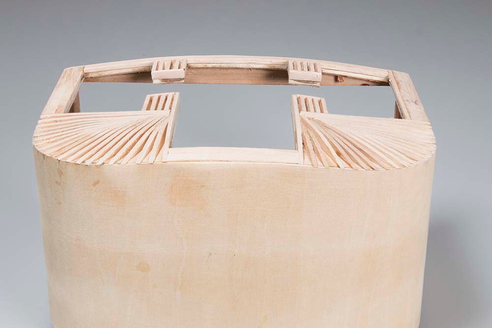
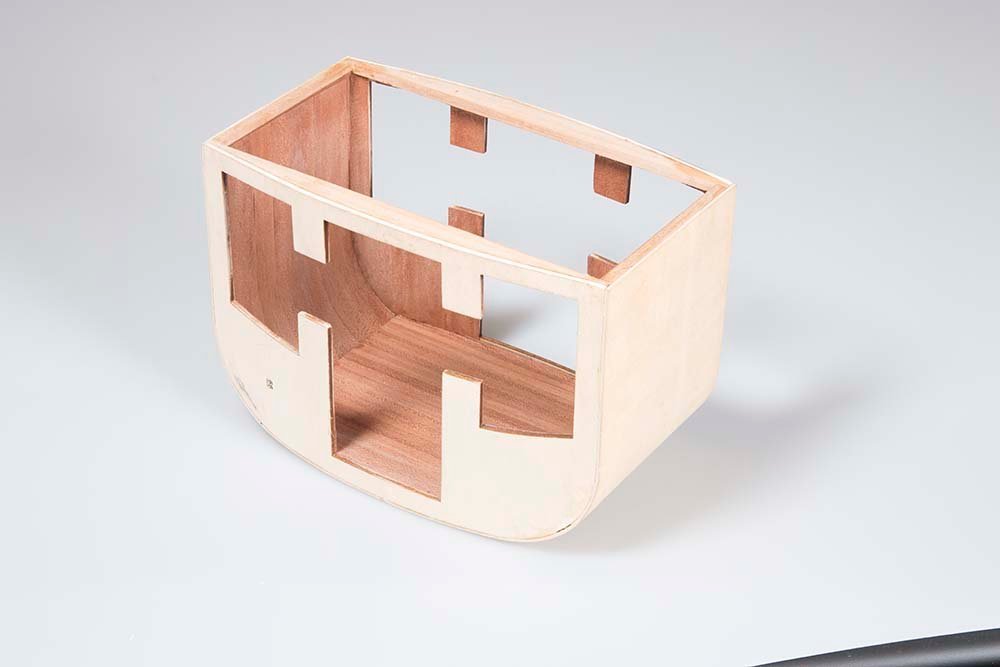
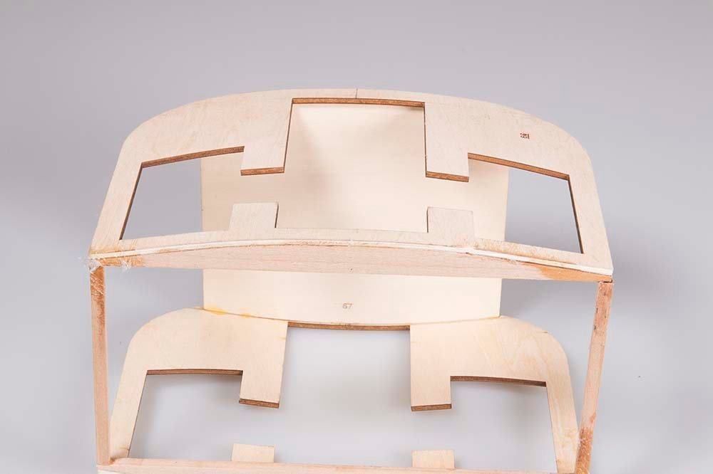
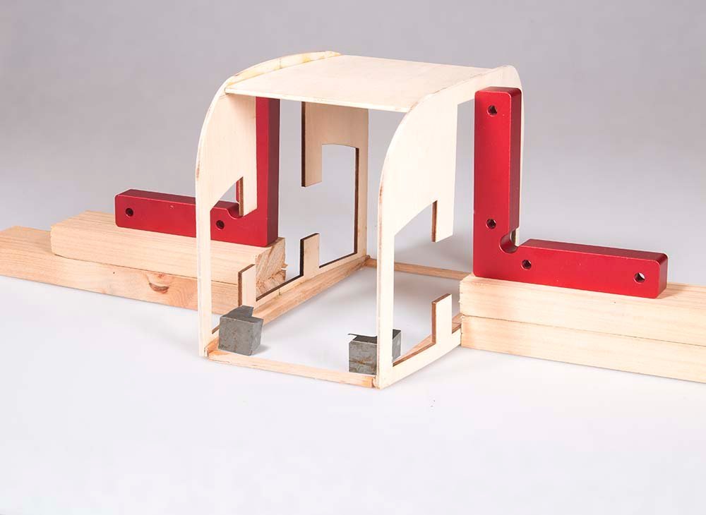
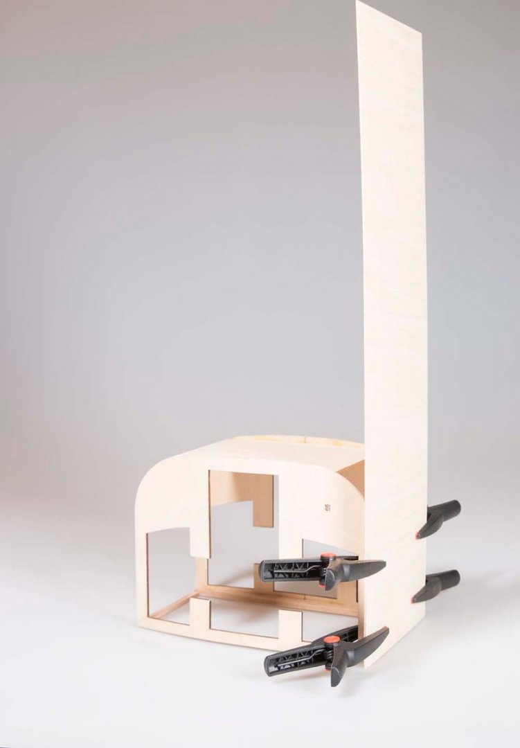
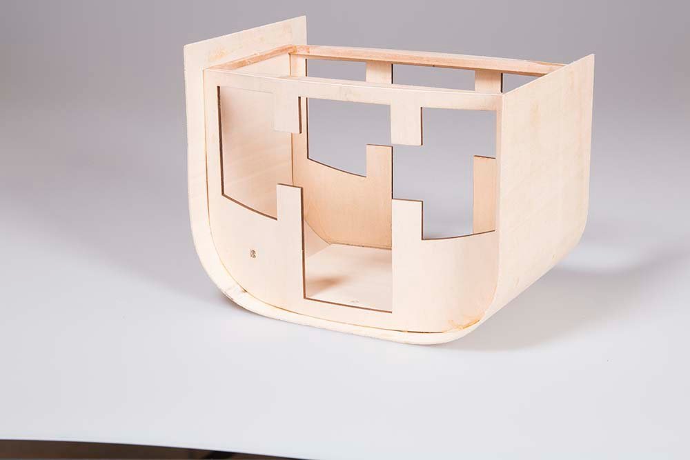
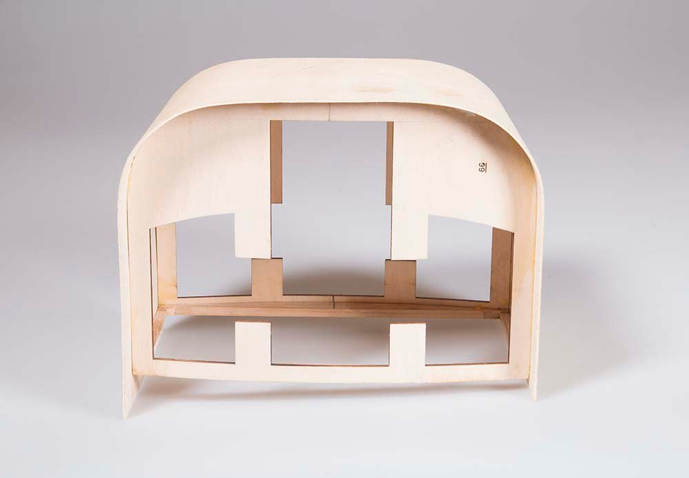
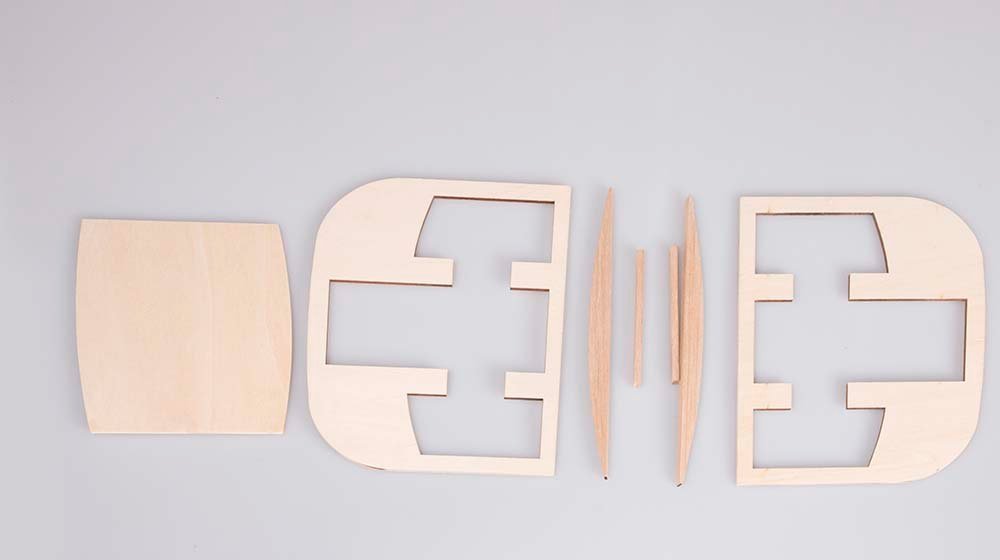
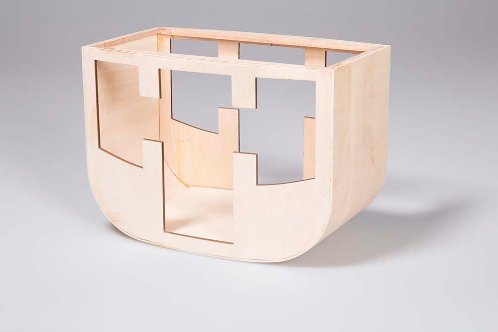
Fabrication of the cabin. With the chasis complete it is time to start on the construction of the cabin, The skeleton of the cabin is made up from the laser cut parts below parts below, which are all supplied in the kit. The curved upper beams are glued to the side panels to establish the curve of the side panels: The second lager curved panel (which is in fact the floor) is then glued just below the door and the two sides are connected together with the short (95 X5 X 4 mm) beams: I found it simpler to build the cabin upside down so that squares can be used to ensure that the side walls are vertical and that the corners are at right angles: Next a 1.5 mm sheet of basswood was wrapped around the sides and bottom of the basic skeleton to form the end walls and the bottom of the cabin. Application of a little water allowed the soft basswood to be bent into a smooth curve to follow the curve of the side panels. It was glued in place with Tight-Bond and clamped for an hour or so: After trimming of the excess and sanding smooth the basic cabin was ready for lining with mahogany veneer. John
-
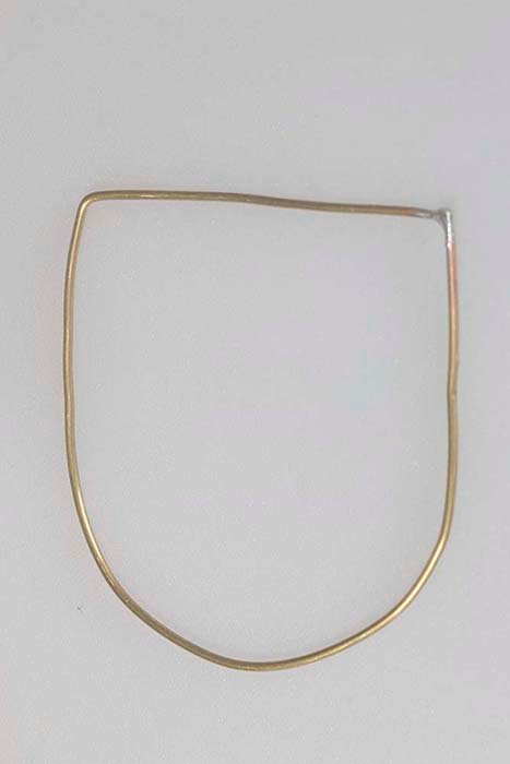
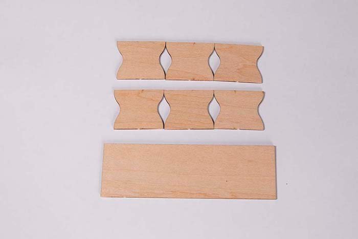
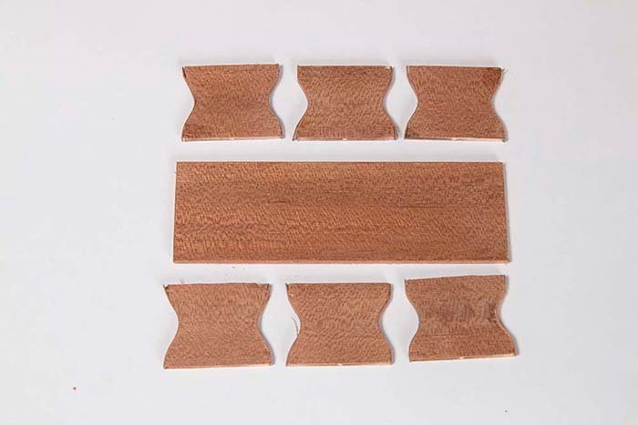
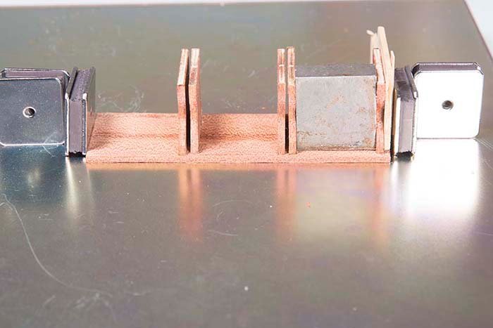
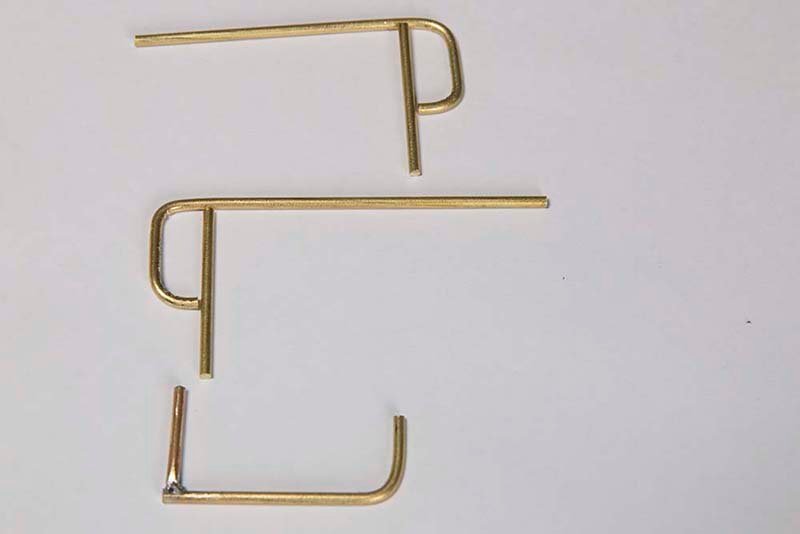
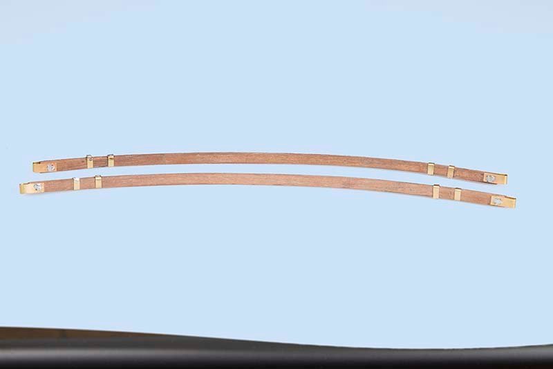
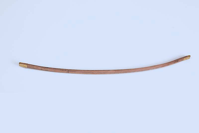
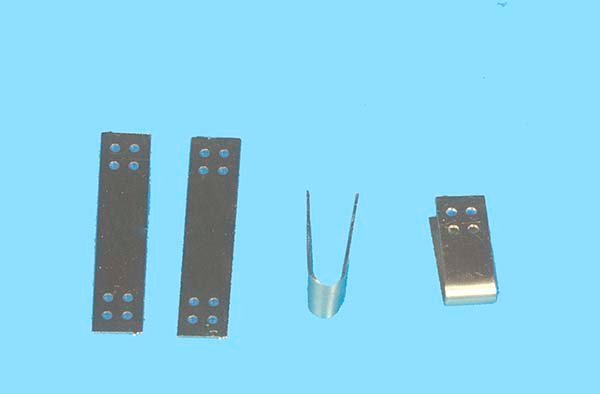
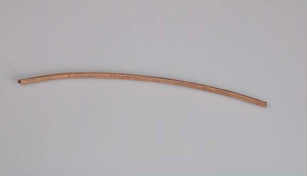
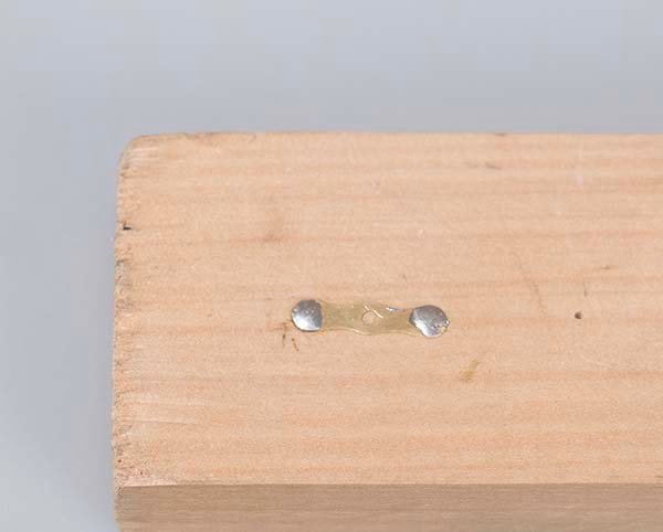
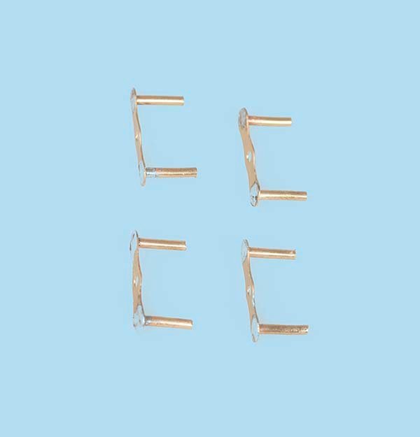
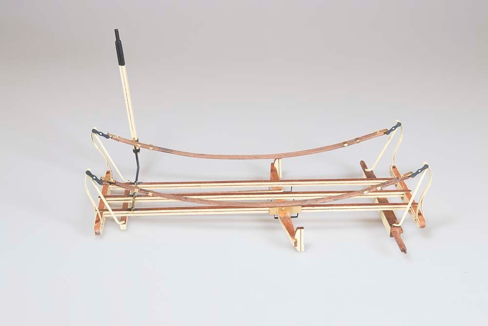
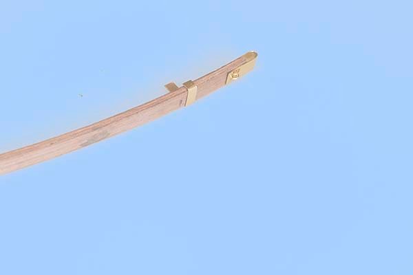
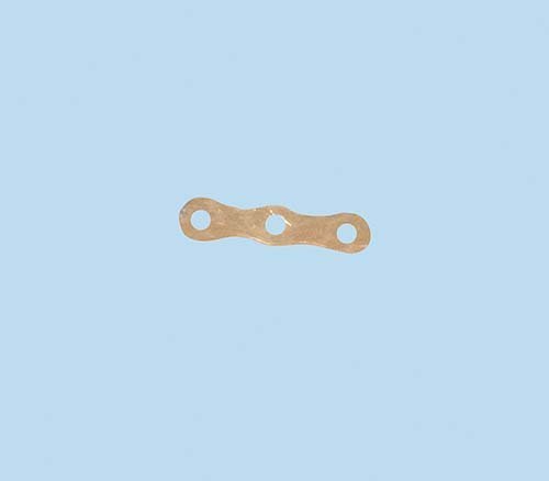
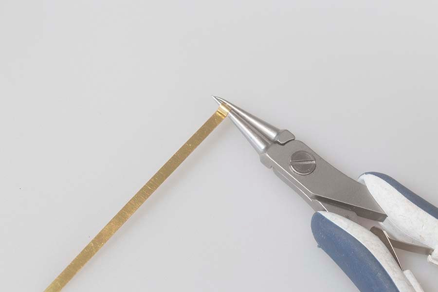
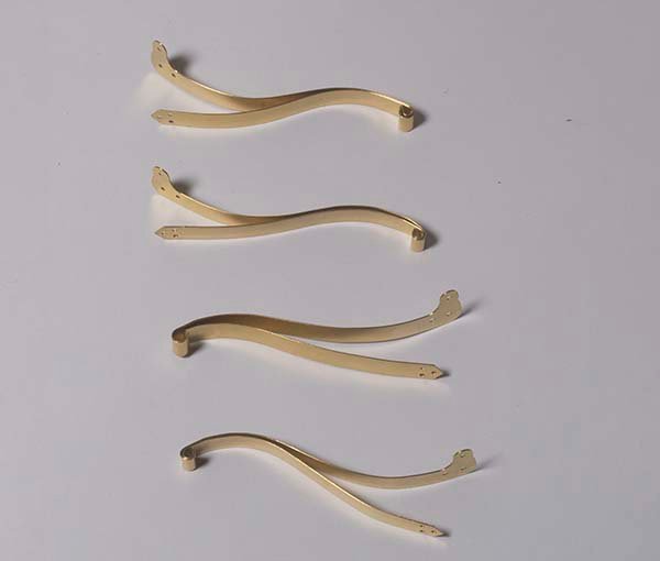
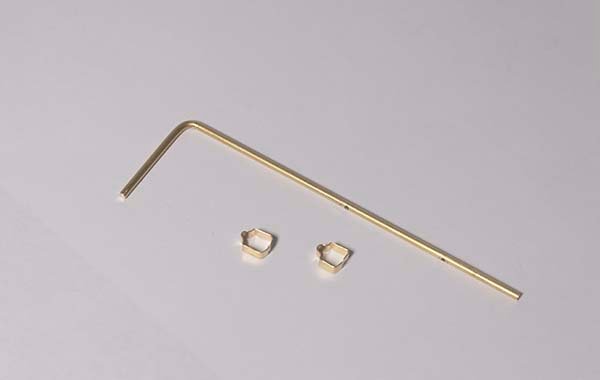
Completing the Suspension 1. The Suspension Links These consist of two brass outer face plates connected by two short brass bars. The face plates are supplied: and the links are cut from 1,5mm brass rod: The instructions suggest connecting these with CA. I felt that Silver solder was more secure but to ensure that the connecting rods were perpendicular I inserted them in vertical holes in some scrap timber and then soldered the l ink on top: The second link is not added at this stage so that the suspension itself can be slipped over the open link. . 2, The Suspension Proper The leather “springs” are simulated by laminating together three strips of 6 X 2 mm walnut: These are glued togeyther with Tightbond held in the appropriate curve and clamped together while the glue dries: The connectors between the suspension “springs” and the links are made the supplied from brass plates which needed to be folded exactly in half so that the four holes line up.: Four aligned holes are then drilled in the ends of the suspension “springs”, The end plates are the “bolted with two U shaped pieces of 0.8 mm wire. Although not detailed in the instructions: I silver soldered the back of mine to secure them. The suspension “springs” unit was finished off with two clamps on each end fabricated from 3mm brass strip. Finally, the completed suspension units were connected to the links and the second face plate added to complete the chassis unit: Time to move on to the cabin John
.jpg.e465bb71d522d868be033aa897ae05a0.jpg)
.jpg.9eebe6ed9385f714d99b327d8e847fa6.jpg)
- 82 replies
-
- 10
-
-
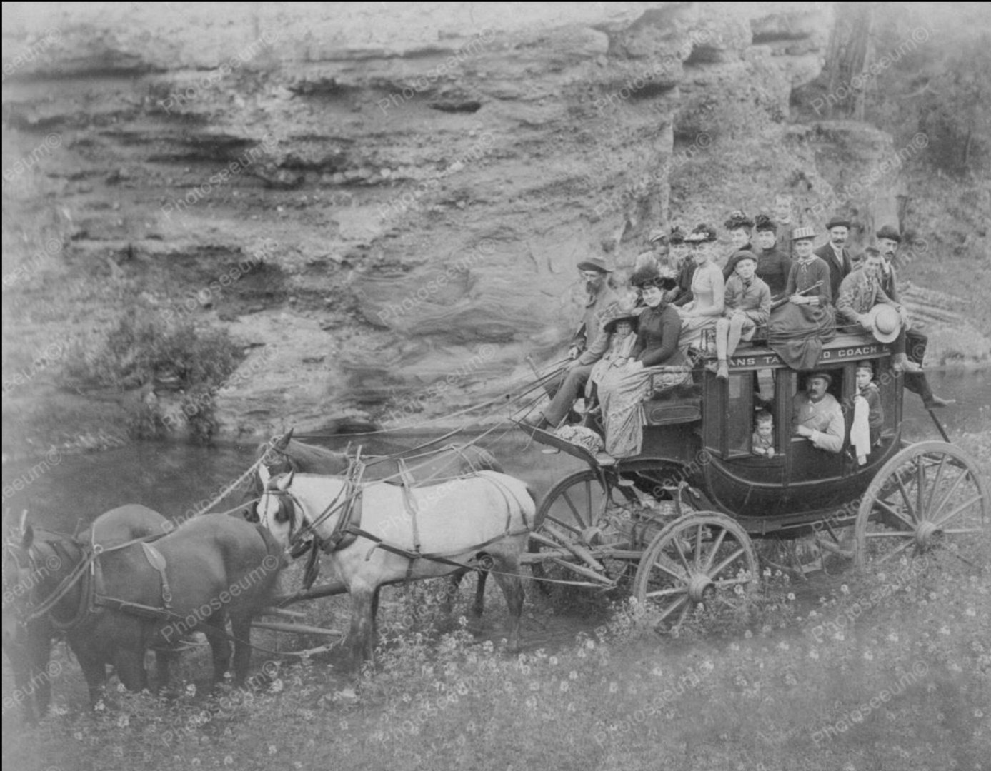
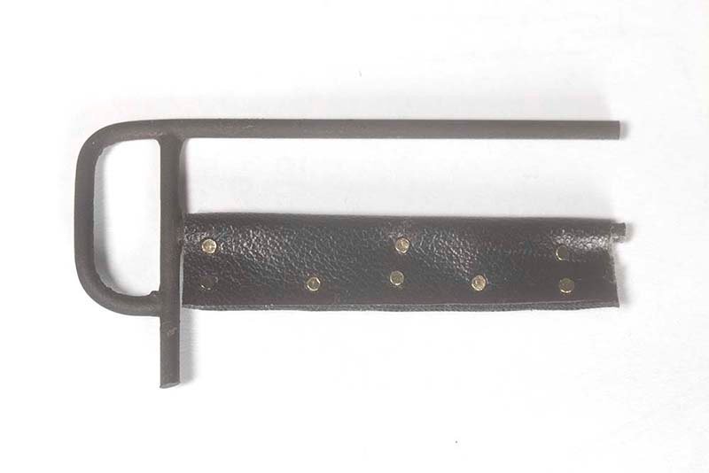
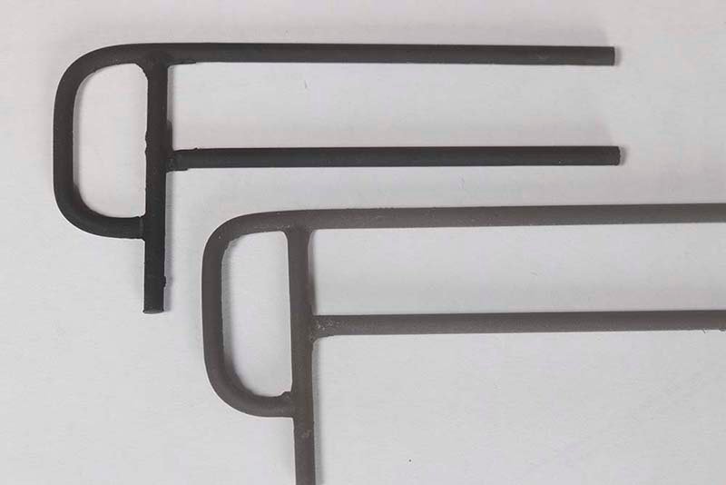
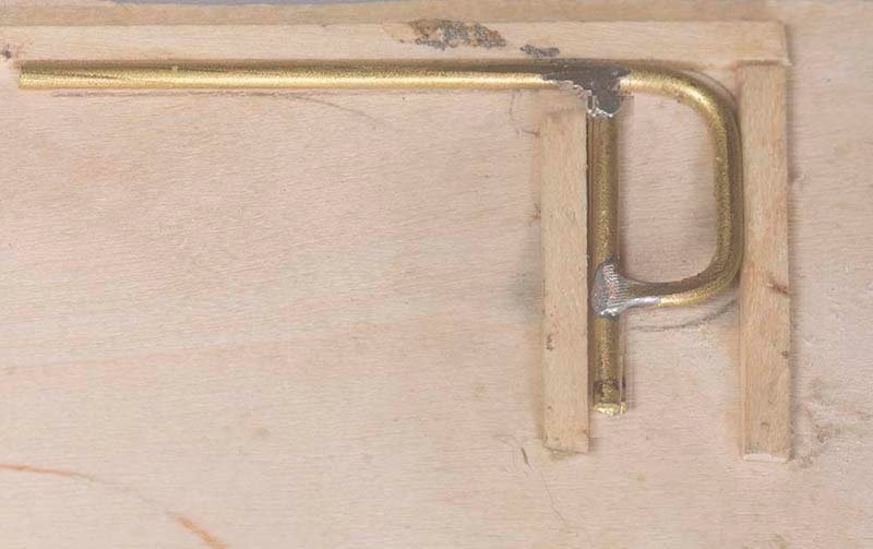
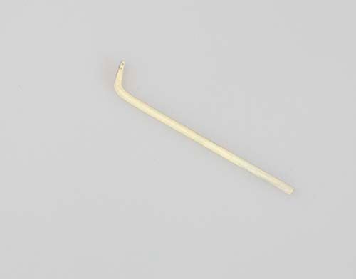
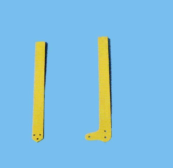
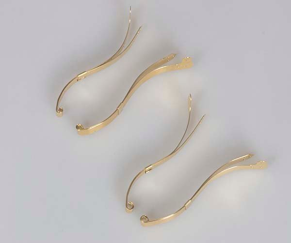
Suspension Brackets These hold the suspension itself which was a strong leather strap on which the cabin was mounted. This was an innovation for the Concornd coach. Apparently the ride was not as good as claimed but it was less tiring for the horses. These are made from 5mm wide brass strip. They are made in two parts – an inner and an outer part: The top section is rolled using needle nosed pliers in such a way that the diameter of the inner section is a slightly smaller than the outer section. In this way the inner section will fit inside the outer section. Since they are not symmetrical, it is important to realise that there must be a left hand and a right hand pair which are of course mirror images. The assembly is then bent into a curved shape using a steel socket of the appropriate diameter. Clamps made from 2mm brass strip were then squeezed with pliers in order to hold the top section together. The brackets were then nailed either side of the stabilizers. Support struts for each bracket were nailed to the rear axel or the front anchoring bar: They were then silver soldered to the back of the suspension brackets. The instructions recomend the use of CA but i feld silver solder was more secure and CA eill not take paint should any touch up needed. Here is the final result: Next links will be made to connect these to the suspension proper. John
.jpg.8252d65e9d60fe68650937b78f1b61aa.jpg)
- 82 replies
-
- 11
-
-
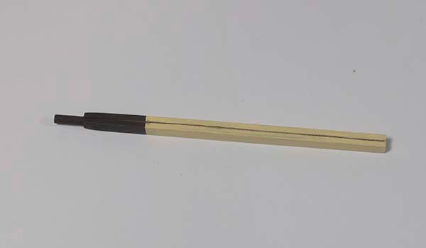
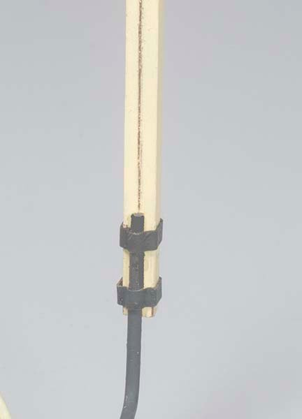
Brake lever The brake lever was fabricated from 5 X 5 mm Sapelly with a 3 mm dowel glued in one end: Two brackets were then made from 3 mm brass strip and the end of the brake bar bent out right angles on its outer end: The brake bar was then secured to the brake lever with the two metal brackets: John
-
Thanks for your kind comments, Glenn. I am in hospital at the moment so this is the first chance I have had to respond. Hoping to get on to another model in a week or so, maybe the Longboat. Unfortunately there are shipping issues from the US to out here at the moment because of Covid. Thanks, again, John
- 160 replies
-
- 2
-
-
- cheerful
- Syren Ship Model Company
- (and 1 more)
-
Thanks, Ric. I know the feeling as I am hospital myself at the moment, though not with Covid. However, it is still frustrating as I would like to start on another model. Regards, John
-
Thanks Dodgeyhack, Chuck, and all of the other "likes". Yes, Chuck, I found it a very satisfying build and I certainly learnt a lot. John
- 160 replies
-
- 2
-
-
- cheerful
- Syren Ship Model Company
- (and 1 more)
-
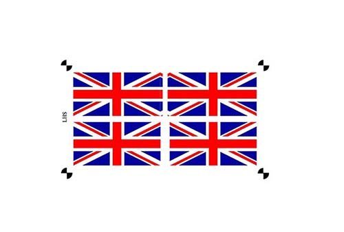
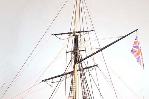
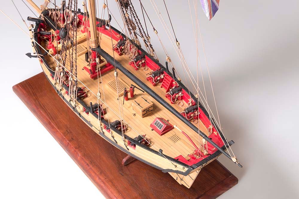
Post 72: Final Touches The Stanchions were turned using a hand drill, small chisels and needle files; The flag was printed on tissue paper. At first I tried printing on both sides using registration marks but exact alignment was still this difficult as the tissue paper moves slightly in the printer. So in the end I used Chuck’s method of printing on one side only and spraying with matt fixative. The flag was then folded over a short length of 0.2 mm thread and attached to the flag halyard: Now , a few photos of the completed model John
.thumb.jpg.80bab4c45ce590903352dd5fdf6a78c0.jpg)
.thumb.jpg.594f5dd97d5e51f9c6f84de3316aa071.jpg)
- 160 replies
-
- 22
-
-

-
-
- cheerful
- Syren Ship Model Company
- (and 1 more)
-
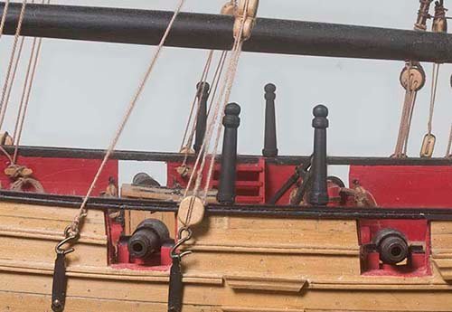
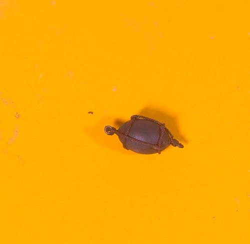
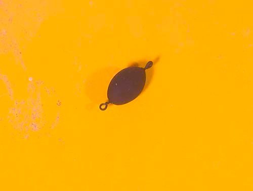
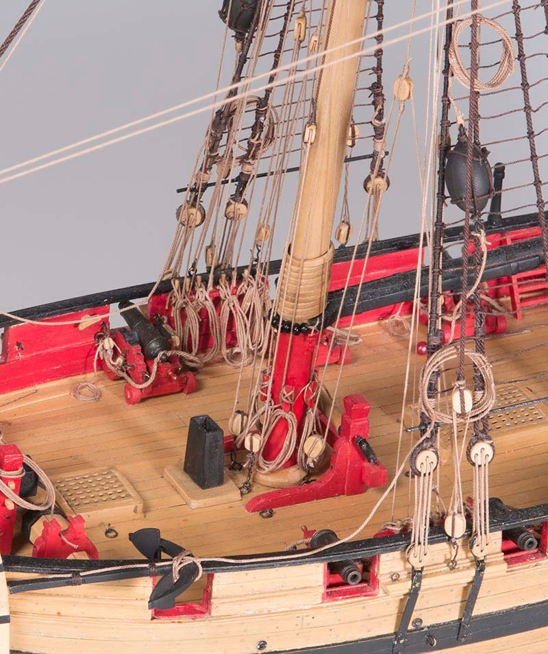
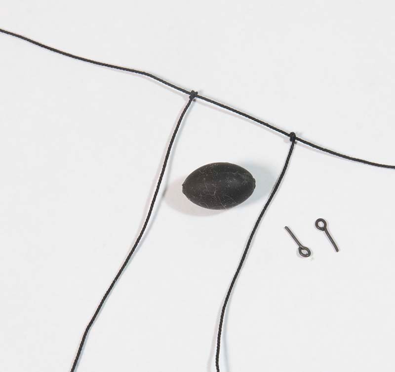
Post 71: Completing and mounting the Anchors After assembling the anchors, they were painted black and weathered in the usual way as described by Chuck. The rope was the attached seized to the shaft The buoys were constructed again as described in the monograh starting with a small bead painted black and weathered and two eyepins glued in. The net was woven from 0.63 mm rope and attached as shown The buoys were then attached to the shrouds: The final step will be constructing the flag and mounting the model. John
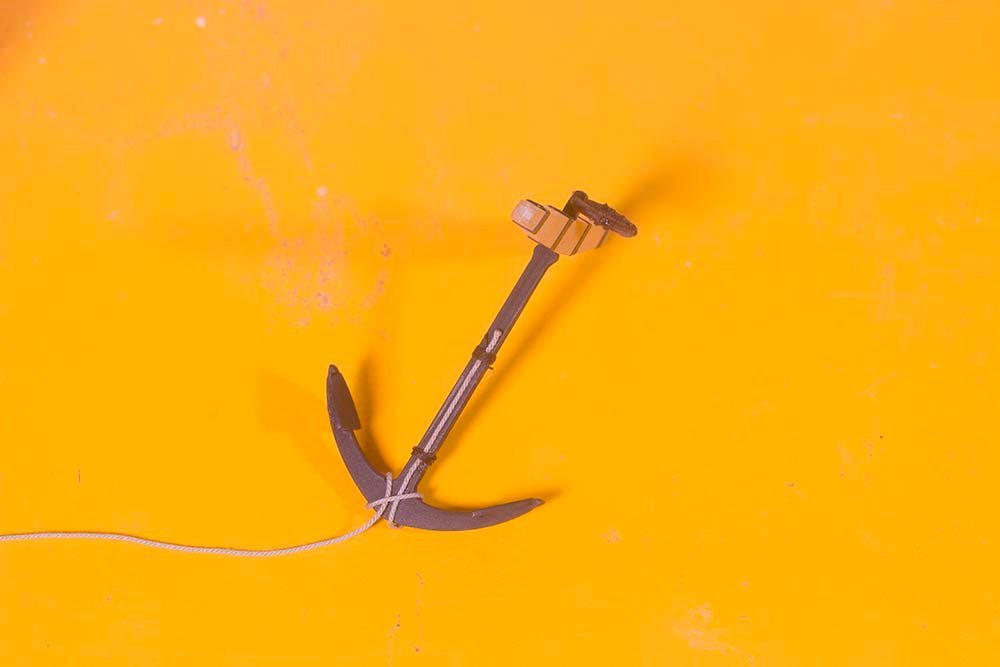
.jpg.90075f7bb4391eeeb8b8d4b38ef77a39.jpg)
- 160 replies
-
- 6
-
-
- cheerful
- Syren Ship Model Company
- (and 1 more)
-
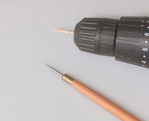
Hi Glenn, Like most of us, I have been through several iterations of this molding thing over the years, but I have now standardised on a method similar to giampieroricci using old hacksaw blades. However, you need to heat them to red heat first or you blunt all your tools. I use my mill with a Dremel disc to cut them as it is precise and reproducible. Unfortunately, I can't find any good photos as I throw them away after use. I'll search about if you are interested. John


.jpg.2e052115c6d4d4e56a3956216a962afc.jpg)
.jpg.c1c8e89aef6aef81bfca397aa0385c05.jpg)