bartley
-
Posts
424 -
Joined
-
Last visited
Content Type
Profiles
Forums
Gallery
Events
Everything posted by bartley
-
Rik, What is shown on the yard that these jeers connect to? Presumably, the matching blocks are shown there. John
-
This is an interesting point. As modelers we often strive too have our yards set square. Indeed when ships were in port, without there sail,s the yards were squared up. Though look atythis photo taken in Cornwall some 20 years ago: Not so square! At sea when the wind was coming from aft (ie running before the wind) the yards would also be squared up. However as the ship came of the wind ( ie the wind from abeam or from the fore quarter0 ,were the sails are drawing rather tan "pushing",, then the angle of the yards would be vary as we moved up the mast. This is because the friction of the wind near the water causes it to move at a different angle than it does at the top of the mast we the wind is more "true". Furthermore, because the wind across the foremast sails alters the direction of the wind across the main mast, the angle of the yards on the main could be different from those on the foremast! So yards would not always be squared or parallel. John John
.thumb.jpg.e2a60dd200be2298394542275d70b6cc.jpg)
-
I believe that the purpose of spirketting was to strengthen the gunwales against the impact of the guns as they are hauled forward. John
-
Here are some numbers for Gutermann thread. The TEX values are supplied by the manufacturer. Diameter is difficult to measure on such fine compressible thread so I have estimated the diameter from the TEX value using a formula which you can derive from the density of the fiber and the TEX number: This will be( sqrt(TEX/1.38 gm/cm^3/314159.27)X20 The density of the fiber is a big issue since only the manufacturer really knows this accurately. As you can see , I used 1.38 gm/cm^3. TEX Diameter Mara 220 13 0.109 Mara 150 20 0.135 Mara 120 25 0.15 Mara 100 30 0.166 Mara 70 40 0.192 Measures about .25 Mara 50 60 0.235 Mara 35 80 0.272 Mara 30 100 0.303 Mara 15 200 0.429 Gutterman C Ne50 20 0.128 This measures about 0.2 and may be 2 ply Vevus 16/0 14 0.113 John
-
Obviously the problem is solved, but for the record there are a couple of ways both of which should work on older versions of Photoshop. 1. Select the pen tool and draw a curve. Now select the type tool and hover over the curve. It will change into a curve tool then you can type on the curve. 2. Type your letters in the normal way (horizontally) Then with this layer selected you should see at the top of the menu on the RH end an icon called "warp text mode". By selecting "arc" in the window which appears you can warp the text by any amount. John
- 857 replies
-
- 2
-

-

-
- Sphinx
- Vanguard Models
- (and 1 more)
-
As Chuck suggests it would be nice to make the letters curve. Somewhere in photoshop there is an option to "print on a curve" Just where it is escapes me at the moment but I will have a look. John
- 857 replies
-
- 1
-
-
- Sphinx
- Vanguard Models
- (and 1 more)
-
If you can afford it I would go with the FX230 because it has a tilting head. If you ever think that you would need to drill a hole on an angle it is the one to go for but it is about 3X the price of the MF70. John
-
Trying to understand white balance
bartley replied to Gaetan Bordeleau's topic in Photographing your work. How to do this.
Back in the days of film, I taught photography in a university for few years. I am not a pro but my portfolio was deemed acceptable for the job. Most students were not going to be photographers themselves but were going to be "purchases" of photography. I used to organise visits to working photographers and on one occasion we visited one of Australia's top fashion and advertising photographers. He was shooting for an advertisement involving a female model. I had expected that he would calculate the correct exposure and take one or two perfect shots. In fact he put his Hasselblad on auto-drive and rotated the aperture ring back and forth while he directed the "talent" to adopt different poses. He never looked at the camera. He took hundreds of photographs in about 20 minutes of the shoot. I was horrified but his view was that poses and composition were paramount and that the client often chose the under or overexposed shot anyway so for each pose he could provide five or six exposures. He was a very successful pro and won many awards.!! John -
Glenn, In my opinion it depends a lot on the timber. I have been scratch building ships and other models as well as furniture for 50 odd years so I grew up with traditional finishes but I have used wipe on poly more recently, On open grained timber, like what we know out here as Huon pine for example, it works almost as well as traditional finishes. It soaks in and is almost gone on the first coat before you wipe it off. But on Queensland maple, which is very close grained it sits on the surface, and when you wipe it off there is virtually no finish left. So I would use shellac or tung oil on that timber. I have not used AYC but I assume it is quite open grained. Also I like my wood to develop a patina and at first I thought wipe on poly would seal the timber and not allow the timber to mellow. However, it does seem to mellow with age once again on open grained timber. Of course this is just y experience and others mayhave different experience. I know a couple of instrument makers and they never stop debating the best finish to use,
- 1,784 replies
-
- 3
-
-
- winchelsea
- Syren Ship Model Company
- (and 1 more)
-
Trying to understand white balance
bartley replied to Gaetan Bordeleau's topic in Photographing your work. How to do this.
I totally agree, Justin, and I am glad to see you use this term. I tried to make a comment similar to this on another thread but was misunderstood and received comments about all photography being "technical" so I thought that perhaps it was a term used only in the antipodes. John -
Thanks for your kind words, Chuck and Joe, and thanks also for all the likes. It is probably going to take longer than I thought to finish off the anchors, buoys and the flag but, yes, close to completion now. It has been a fascinating build and I have learnt a lot. John
- 160 replies
-
- 1
-
-
- cheerful
- Syren Ship Model Company
- (and 1 more)
-
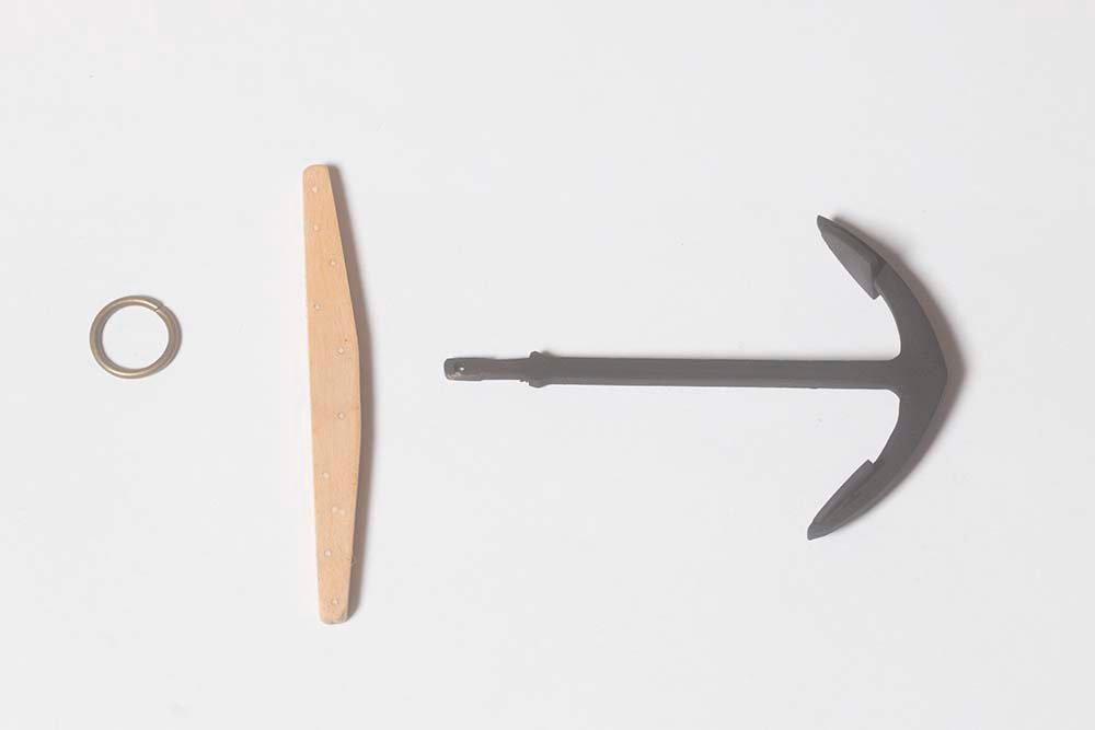
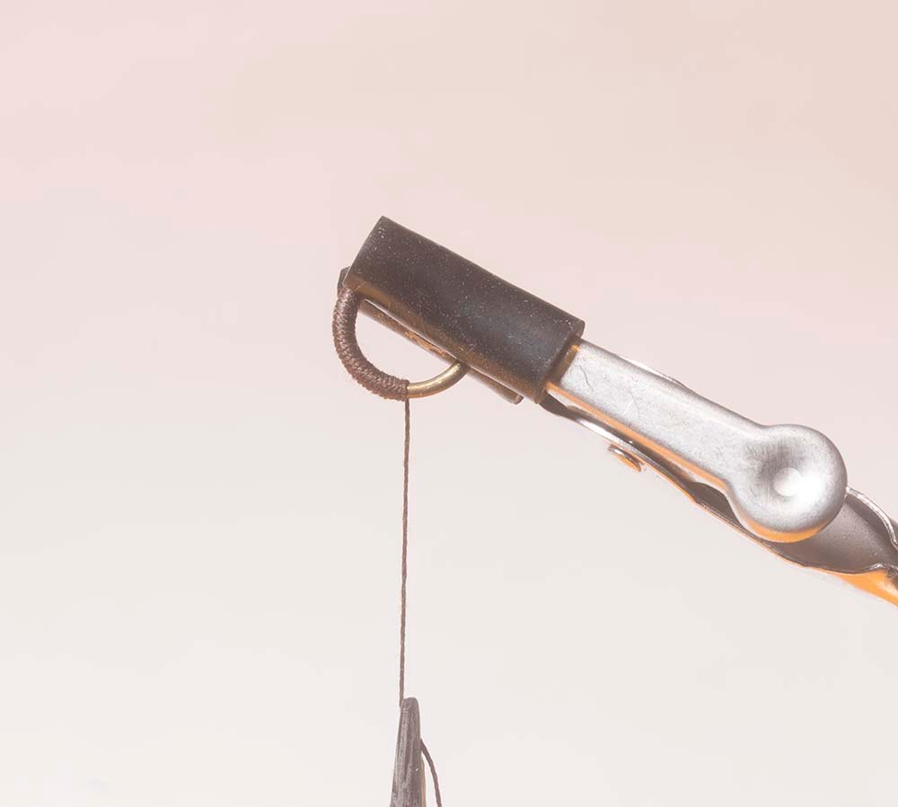
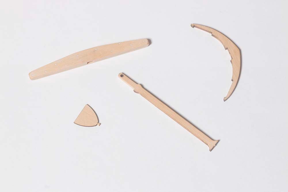
Post 70: A little more progress Domestic and family issues have slowed me down a bit of late but all rigging has now been tied off although there are a few more rope coils to go. However I have started work on the anchors which are made from one of Chucks nice little kits. Treenals were simulated on the stock by drilling and filling as on the hull and the anchor itself was painted black and then treated with weathering powder to make it look more like metal. The Puddening was carried out by wrapping the ring with Mara 70 thread.

- 160 replies
-
- 10
-
-
- cheerful
- Syren Ship Model Company
- (and 1 more)
-
Focus Stacking
bartley replied to Dennis P Finegan's topic in Photographing your work. How to do this.
If you look at my post # 21 above you will see that I refer to this technique to avoid the strange perspective that arises from using rails on larger objects.. John -
Focus Stacking
bartley replied to Dennis P Finegan's topic in Photographing your work. How to do this.
A good result and a pretty good model too boot! John -
Focus Stacking
bartley replied to Dennis P Finegan's topic in Photographing your work. How to do this.
The definition DOF is not a simple matter since it is not a fixed optical parameter. It depends ultimately on ones definition of the "circle of confusion" which is the amount of blur that the human eye will perceive as a sharp point when the image is viewed at normal viewing distance. Since the eyes of different individuals vary, the circle of confusion is, in principal, a personal thing. There is of course a definition of the circle of confusion - in fact there are several so I would call it a convention. To further complicate matters, real lenses do not focus rays precisely anyway so that a point is not focused as a point focused but as a small spot. One of the advantages of focus stacking is ,that if we take enough images, each image has an area that is a sharp as the lens iis capable of so all of the above assumptions don't matter, Incidentally, because of the graph shown by Dr PR you need to take more images at closer distances. Our rails are run under computer control and we program to do this. We use Nikon cameras and others and for the very close work we do the rail gives less artifacts than the Focus shift in camera method. On this rail issue it would be ludicrous to try to use a rail on a landscape photo, for example and although we have used the rail technique to photograph some quite large objects focus shift is probably just as good. One other thing about the rail technique for larger objects is that the perspective is somewhat unusual. We often use tilt /shift techniques to avoid this. John -
Focus Stacking
bartley replied to Dennis P Finegan's topic in Photographing your work. How to do this.
The problem is, Glenn, that theory is not always born out in practice. Your Nikon is changing the focusing point gradually during the collection of the images. Theoretically the size of an image should not change as you change the focus but manufacturing tolerances of the lens and other factors result in what is called "focus breathing" , This means that the focal length changes very slightly as you change the focus, hence the size of the image. One of the lens elements has to move to change the focus and it is almost impossible to do this without effecting other elements. This effect is, of course, dependent on the lens design. The real question is would you notice it? Probably not in everyday general work, such as the photo you describe of Cheerful, but in technical photography it becomes very important. John -
Focus Stacking
bartley replied to Dennis P Finegan's topic in Photographing your work. How to do this.
You are quite correct, Justine. There are many scientific applications of focus stacking and we always use a rail to do this. Changing the focal point, especially with a zoom lens, causes a marginal change in size and so greater demands are placed on the software. Even so the quality suffers especially at the edges of the frame. You may interested to know that in medical imaging and in forensic applications we take multiple images and then use mathematical functions to look for differences between images. John -
It is good that you are able to deal with them. WE have a problem in Australia with Amazon , Google and Facebook. They refuse to pay our income tax for business they do here and will not pay our media companies for the news that they use. So most of us use alternatives which in the case of Amazon are not so extensive. John
-
Thanks, oldmate. Yes I have been a bit on-and-off on mine. Other hobbies. Other builds even. But you should persist. It's a great build. For me, lots of challenges. But all can be overcome and very satisfying then. Cheers, John
- 160 replies
-
- 1
-
-
- cheerful
- Syren Ship Model Company
- (and 1 more)
-
I have made fine furniture for many years and have used both, On open grained timbers wipe-on-poly can look quite good if you wipe it off quickly and it is very durable so it is good on surfaces which will be subjected to wear and tear. However, in my opinion, there is no comparison to the patina of shellac. As someone else said, it becomes richer over the years. It is, after all, French Polish although you could not apply that technique to a model. In fact when I apply shellac to a model I wipe it off quickly just like you would with wipe-on-poly, If you do a side-by-side test on whatever timber you are using you will probably not see much difference. I t will only be when you look at it a year or so later that you will start to see the difference. John
-
Shellac for me as well. I don't like the "synthetic" look of wipe on poly. John
-
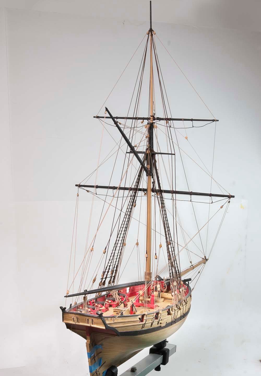
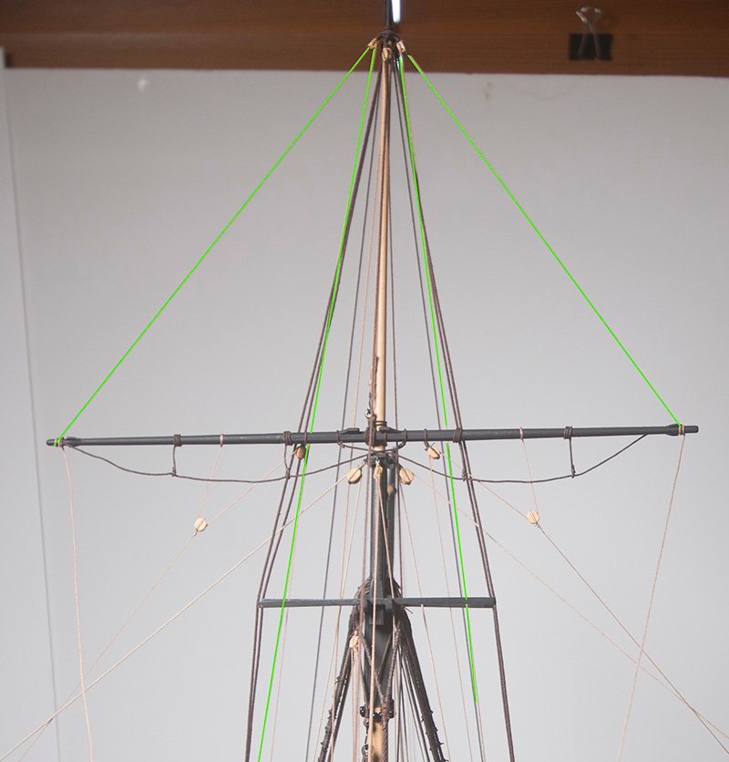
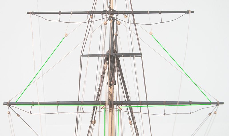
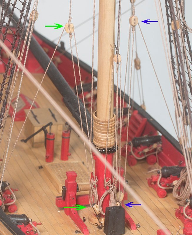
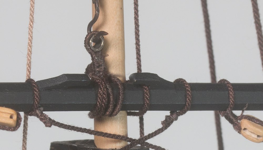
Post 69: Installation of the Topmast Yard The first task was to attach the truss, which was seized around the mast to hold the yard in place. Attachment of the halyard was straightforward. A hook was seized to a length of 0.63 mm rope which was attached to the sling. It was then led down to a tackle on the starboard side which was an exact mirror image of the topping lift tackle on the port side: Aligning the yard proved more difficult than I thought. First I fitted the clue lines and sheets since these were the inner ropes. I then used the tension on these to establish the correct angle for the yard. However since these also connect to the main yard tenshioning of these caused movement of both yards. So in the end I left these slack while I adjusted the angle with the lifts and braces and the re-tenshioned the sheets and clue lines quite loosely later. My alignment eye was checked with a laser level: John
- 160 replies
-
- 6
-
-
- cheerful
- Syren Ship Model Company
- (and 1 more)
-
Paul, I like the look of these jigs. The only thing I would say is that 26 mm is a pretty big coil. When these are made in practice one holds the rope in each hand then stretches the arms out letting the rope slide through then bring the hands together to make a loop if this makes sense. The point is that the diameter of the loop is about half of your arm span. On our boat our coils were around 800 mm give or take, so you can work out what this would be at scale - around 16.5 Anyway, your model is looking great. A step above mine, I think Regards, John
-
Paul, I agree that wrapping the serving over the seizing looks better. For what is worth, I am now using Mara polyester thread for serving. I found the cotton thread was a bit furry and Mara gives a smoother result in my opinion. Because I am winding my own rope I have this in various sizes and I like to use thinner serving thread on thinner rope. If you use 50 wt thread on say 0.45 mm rope it almost doubles the diameter. This looks wrong to my eye. Regards, John
-
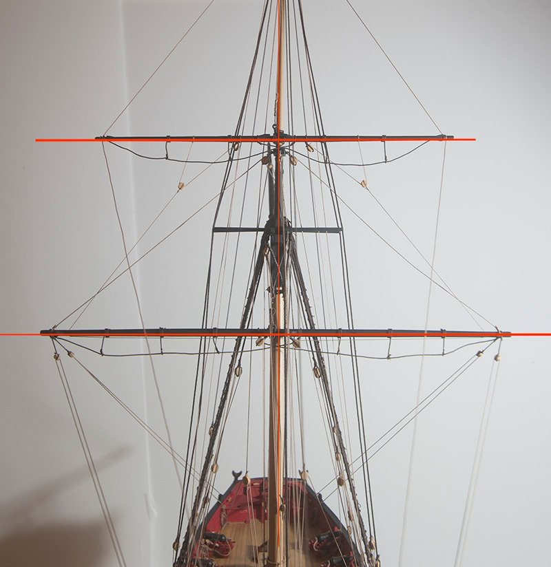
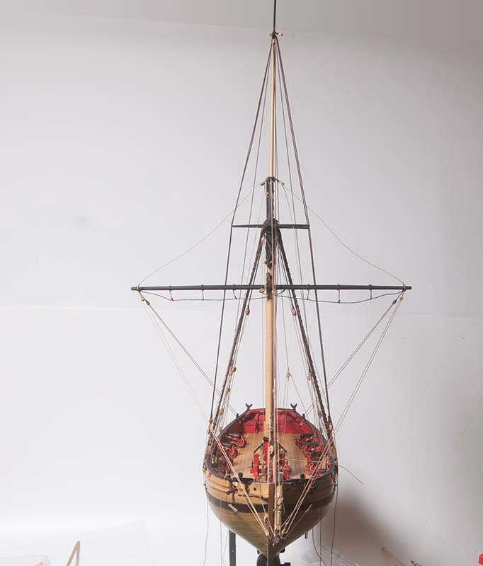
Post 68: Installing the Main Yard I have spent some time doing a final tidy up some of the belayed lines and trimming them off. Now it is time to install the main yard which was constructed some time ago. In principal the lifts control the vertical tilt and the braces the for and aft tilt. However, because the braces exert a downwards force I found that they really control both movements. I initially squared up everyting by eye but the laser showed I was a little off and helped me to be more precise: On the whole I am pretty happy with the way it looks but nothing is tied off permanently just yet and obviously the lifts are yet to be belayed. John

- 160 replies
-
- 7
-
-
- cheerful
- Syren Ship Model Company
- (and 1 more)
.jpg.727d98d1ecfcc865fa92a6638466224a.jpg)