HOLIDAY DONATION DRIVE - SUPPORT MSW - DO YOUR PART TO KEEP THIS GREAT FORUM GOING! (Only 13 donations so far - C'mon guys!)
×


Ian_Grant
-
Posts
2,113 -
Joined
-
Last visited
Content Type
Profiles
Forums
Gallery
Events
Everything posted by Ian_Grant
-

Great kit and parts source
Ian_Grant replied to JohnU's topic in REVIEWS: Model Shipwrighting Tools, Parts and fittings
I agree that hobby shops are scarce on the ground now compared to the 70's - 80's. I am lucky in that I have two excellent hobby shops within 5km here in west Ottawa, and another downtown. One specializes in RC, mainly planes but some power boats, with lots of stock of electronics. The other specializes in plastic models, lots of cars, planes, tanks, and a few boats. Downtown has trains and plastic models. I try to buy from the two nearby when possible - paint, glue, evergreen, brass extrusions. But model ships are a niche, model sailing ships are an even narrower niche. None of these stores carry ship fittings. There are probably ten people in town who would need them. Regrettably, modeling is a dying hobby. One store owner told me that his customers are all my age (60's) getting back into the hobby now that the kids have left. The kids never got interested in models. I tried with my son but no dice. We're lucky to have the internet to reach out to wherever the excellent shops carrying ship stuff are located. -
Great kit and parts source
Ian_Grant replied to JohnU's topic in REVIEWS: Model Shipwrighting Tools, Parts and fittings
I have bought here in the past and like them very much. I cannot understand why shipping something from the UK to Canada is often far cheaper than from the USA to Canada. I've experienced this with model parts, books, and kits (not all from CMB!). I also liked The Model Dockyard but Nick recently retired... -
Thank you Vic and Cirdan! I wanted to move on to the topgallant mast fittings but I am now out of etched brass eyes. Waiting for an order to arrive. Not sure what to do on the ship in the meantime.... Oh, and I finally got a COVID shot - Pfizer - yesterday. My arm's a bit sore today but I'm happy!
-
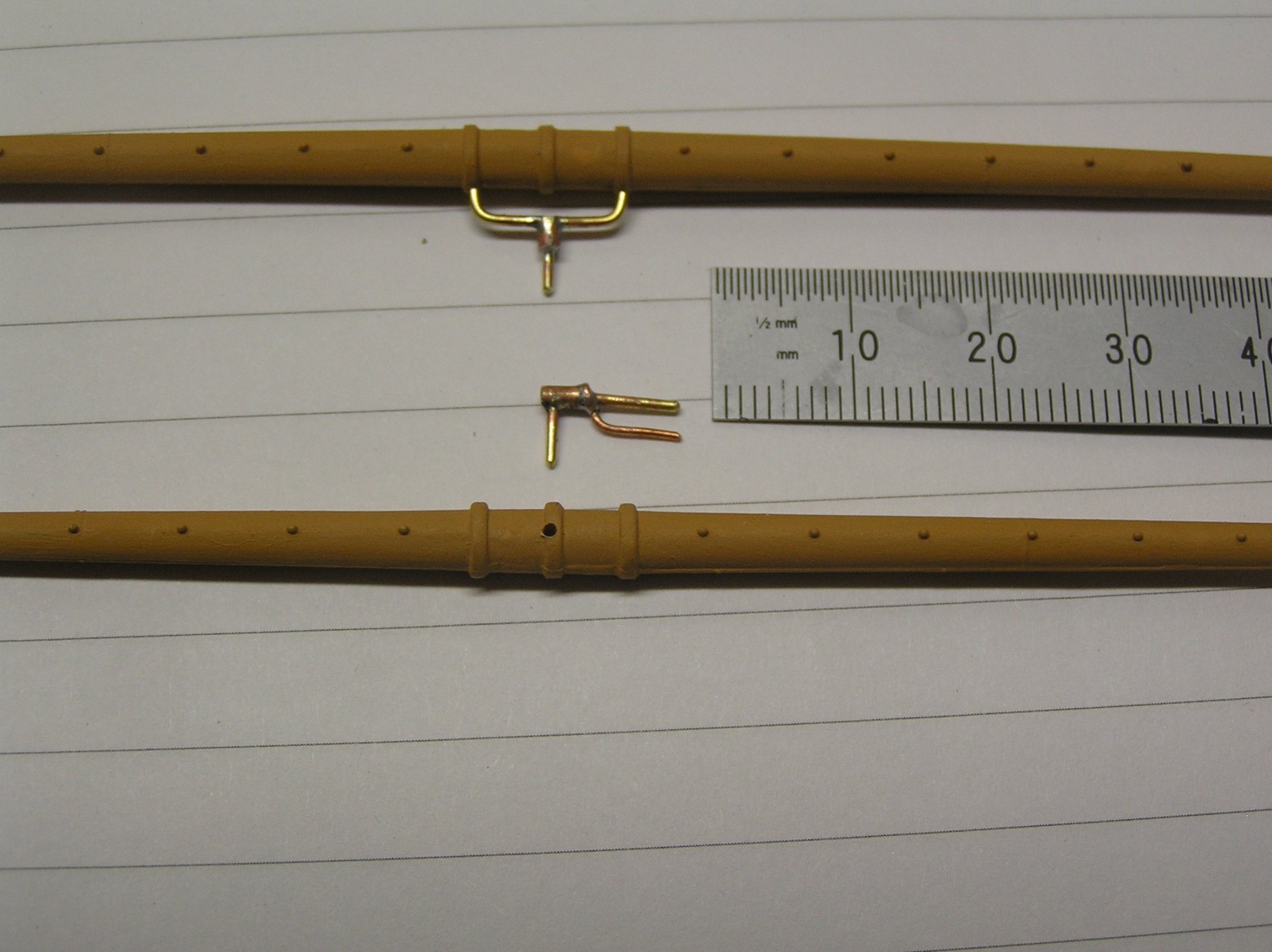
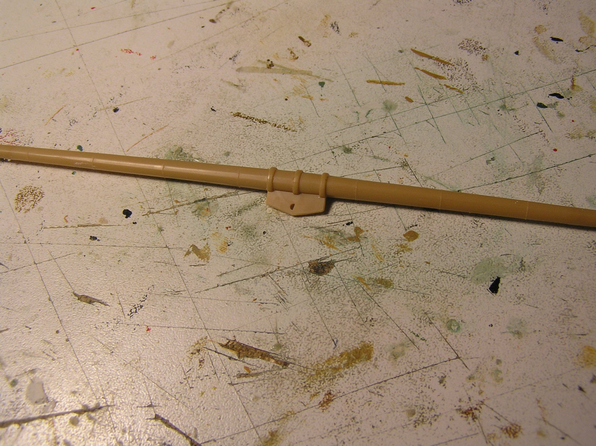
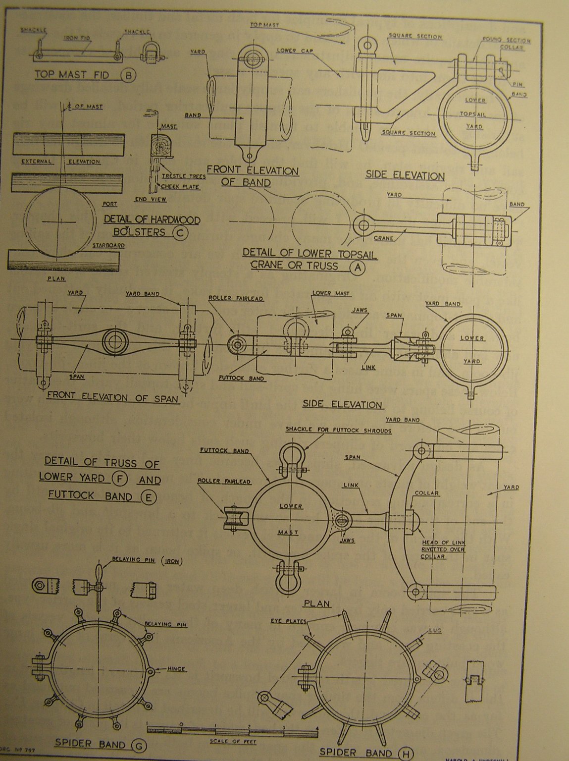
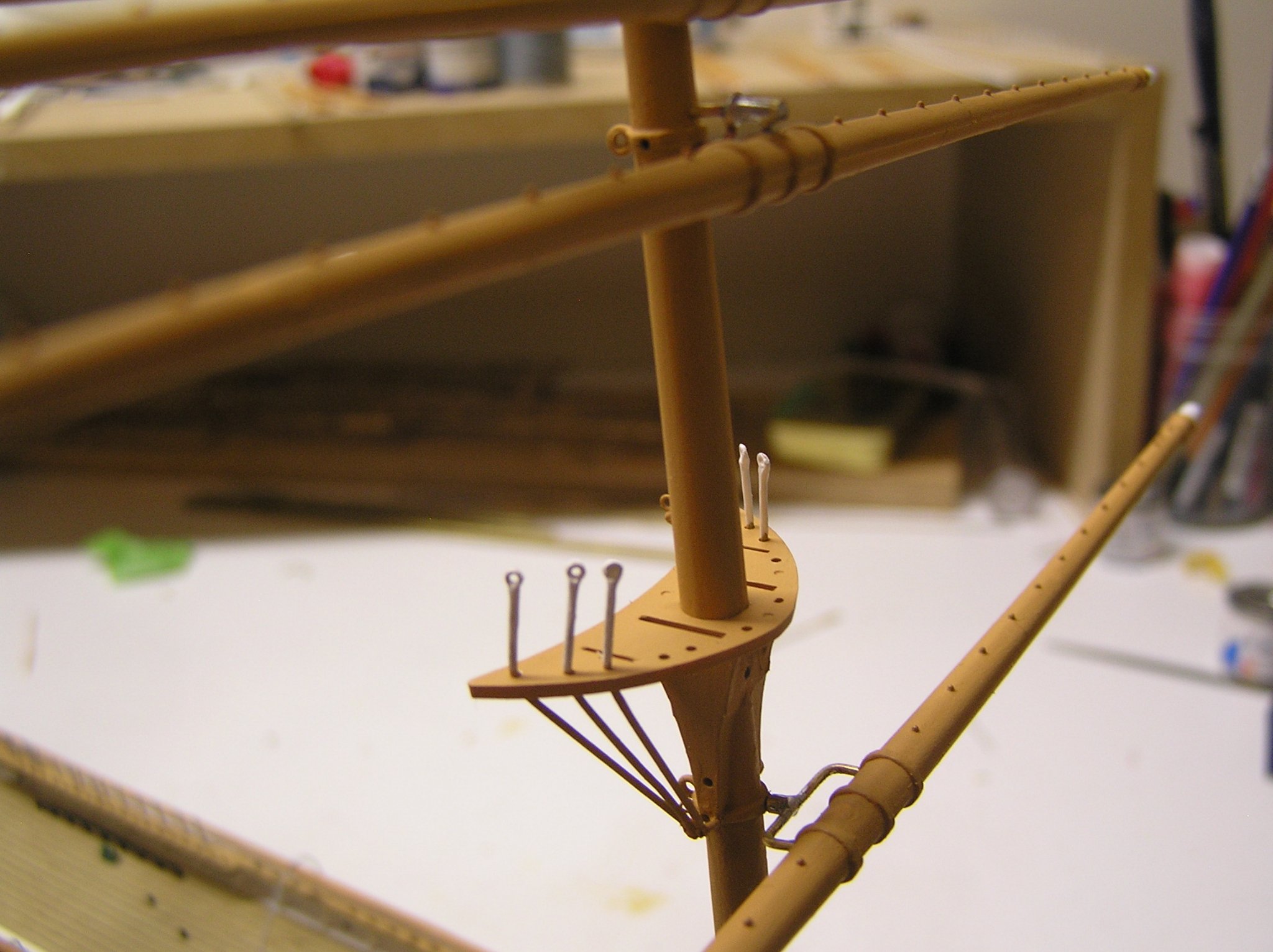
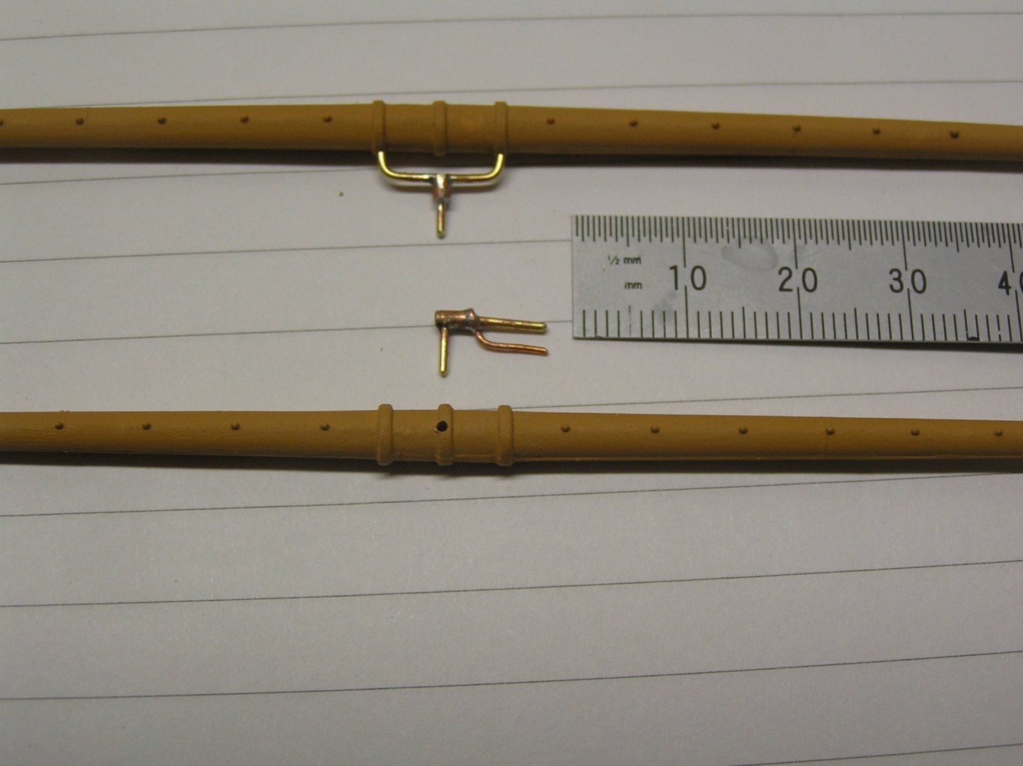
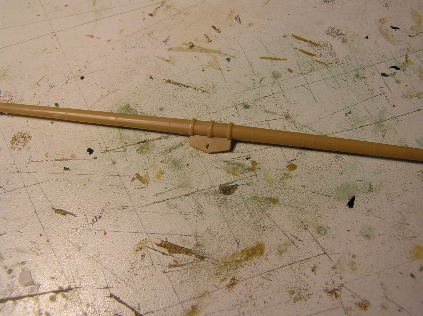
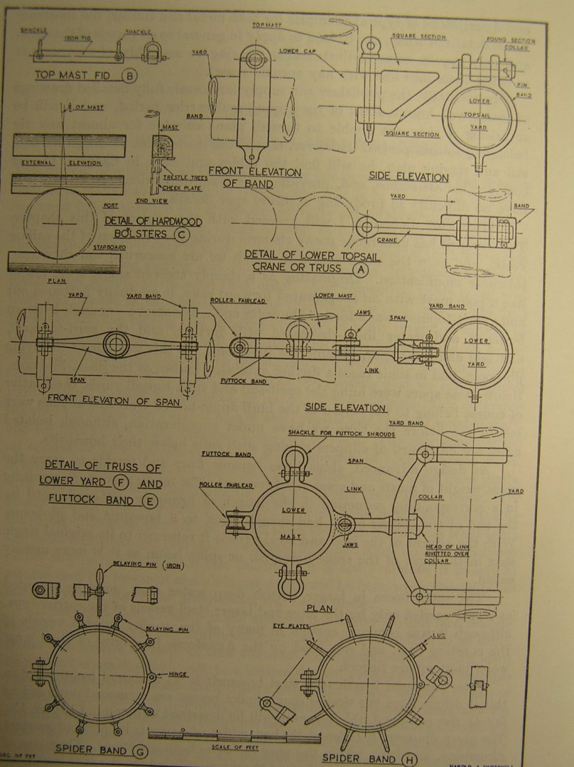
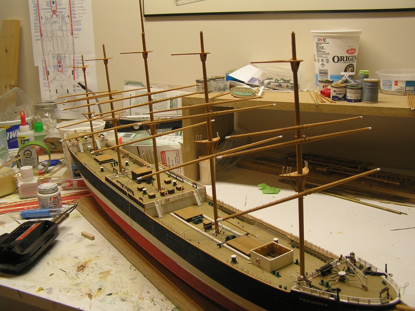
I take back what I said last post about the "many ladders". There would not be that many under the bridge deck; I now think many of these "boxes" are skylights elevated above the deck in case water is sloshing around, that can be propped open for ventilation. Would be nice to tour one of the museum ships and find out! Latest update is that I finally made some brass yard trusses. Given my poor soldering results in the past, I tried two new steps in the process: washed the brass parts in vinegar then rinsed in water, and applied flux where they join before soldering. Also touched only with tweezers after rinsing to avoid skin oils. Results were good. I just used the same flux I've used for years when sweating copper water pipe and fittings. Here is a shot of a lower yard with its truss, and a lower topsail yard with its truss unconnected. The lower yard truss is made of two brass rods, one bent into a "C" shape, joined with a short section of tubing. The tubing was notched across one end so as to partially contain the "C" rod thus lending strength to the joint. The lower topsail truss is an "L" brass rod, with again a short length of tubing, and a copper eyelet shaped suitably. This truss goes into two holes in the mast placed just below and just above the lower mast cap (notional in these one-piece steel masts). It enters the yard's centre band at the top of the yard. Just for fun here is a shot of a yard as supplied by Heller, which I showed very early in this log. Here is a figure from Underhill showing what I'm trying to emulate, or at least sort-of represent. The two trusses in place on a mast. And lastly the ship with all lower yards crossed. Finally looks like a ship! The upper topsail yard joins the mast with a simple straight piece of rod drilled in yard and mast to represent a sliding parral. Luckily Heller molded a band I could use for the "parral". Excuse the odd angles - rigging will straighten out the yard alignment. The upper topgallant and royal will be joined this way too but the lower topgallant has a truss like a scaled-down lower topsail yard. Not sure what I will do as the topgallant yards and masts are significantly more slender.

-
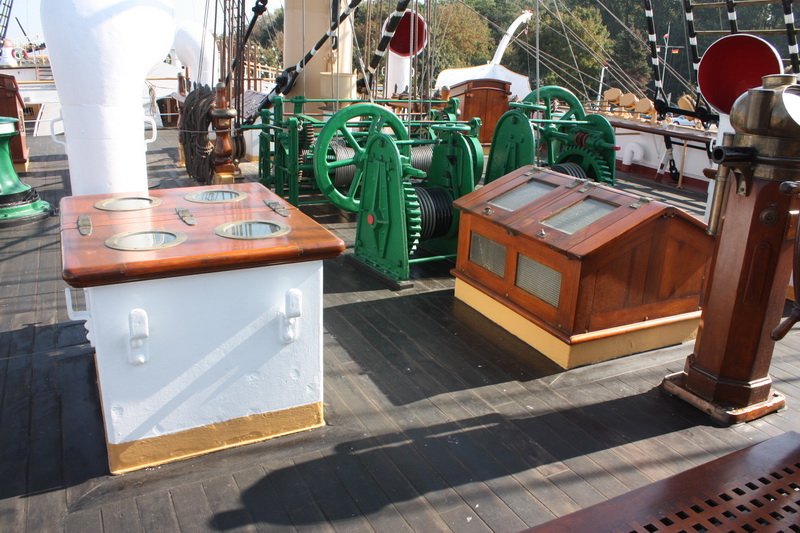
Hello gak They're actually hatches with portholes for skylights. There must be a mass of ladders under the bridge deck! Here's a shot of some on the "Passat":
-
Hello, I believe the galley chimneys could be rotated by the crew to point them downwind. That's why you see many models on MSW with handles on the chimney, like "ears". Keep up the great work!
-
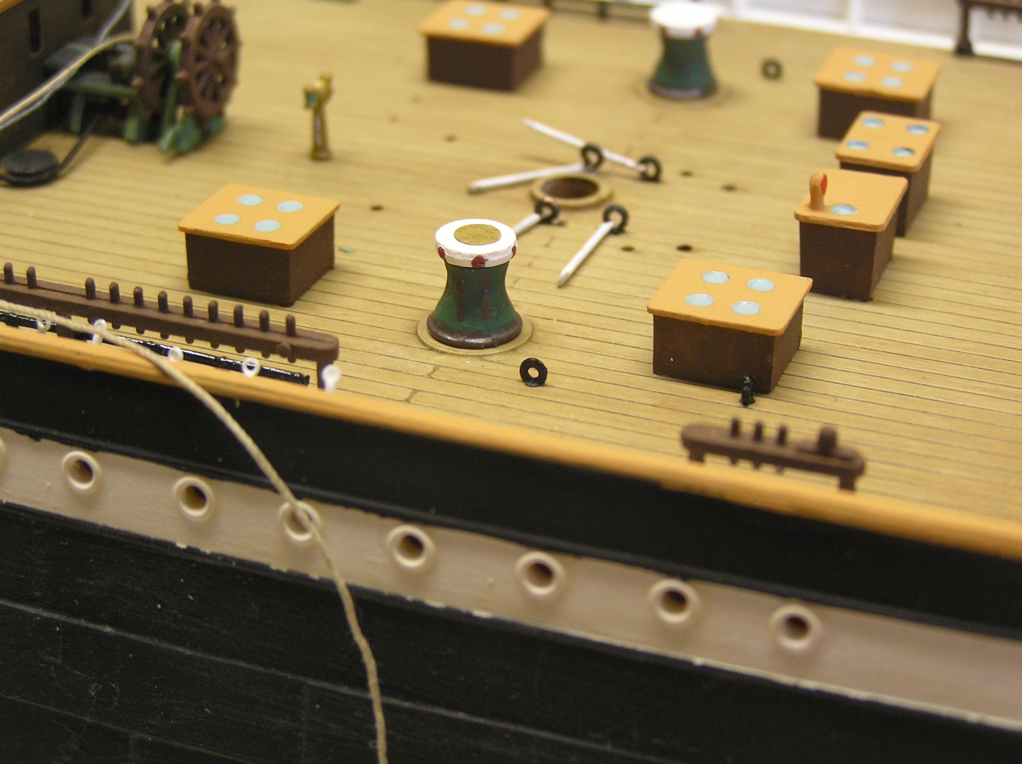
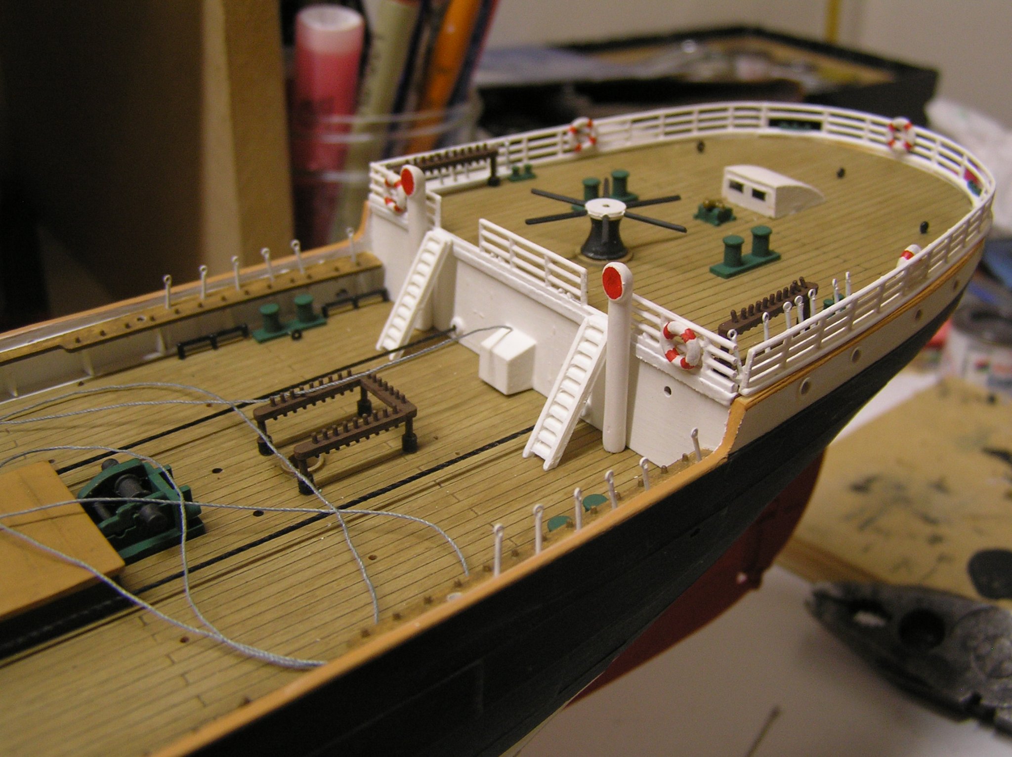
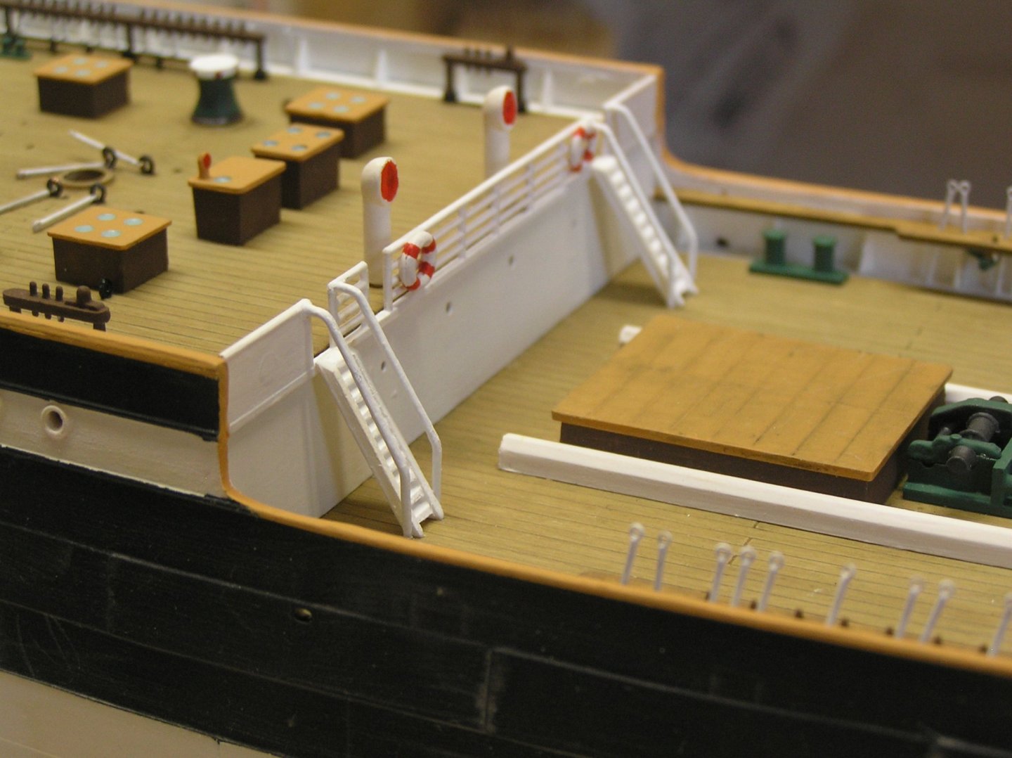
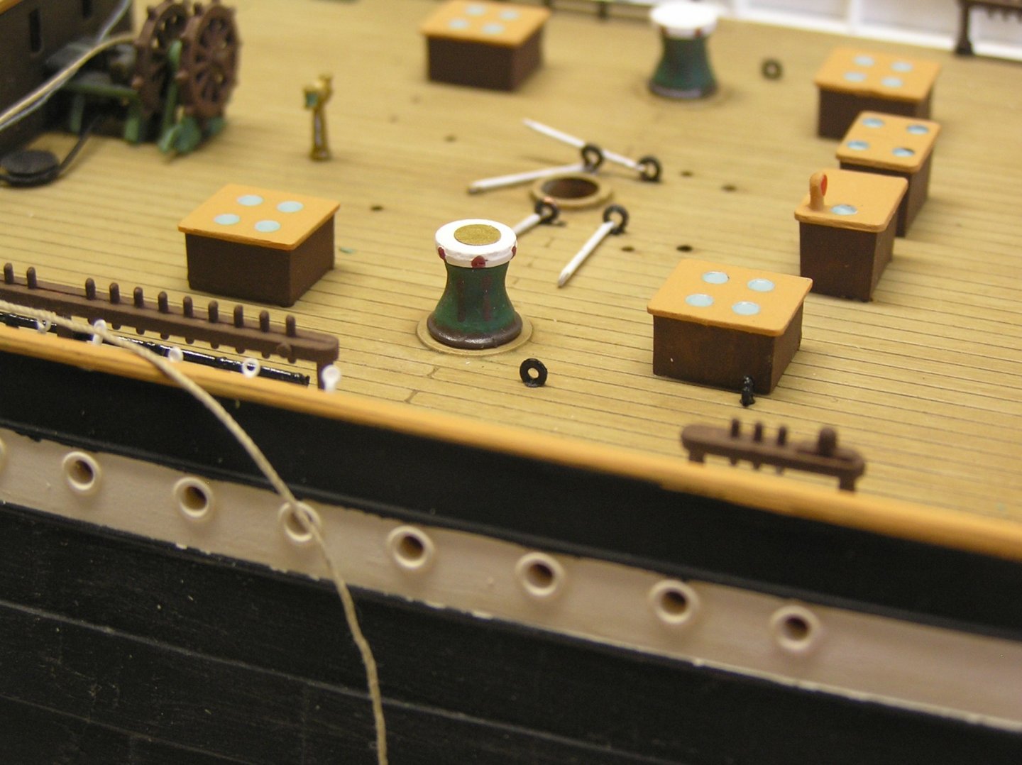
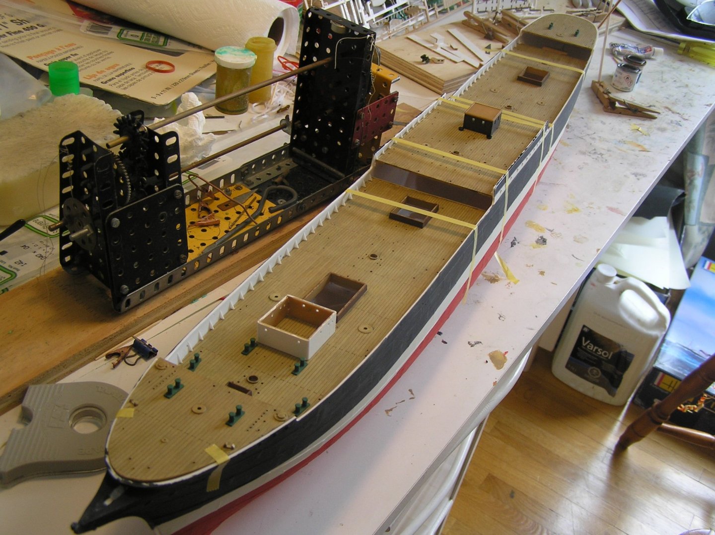
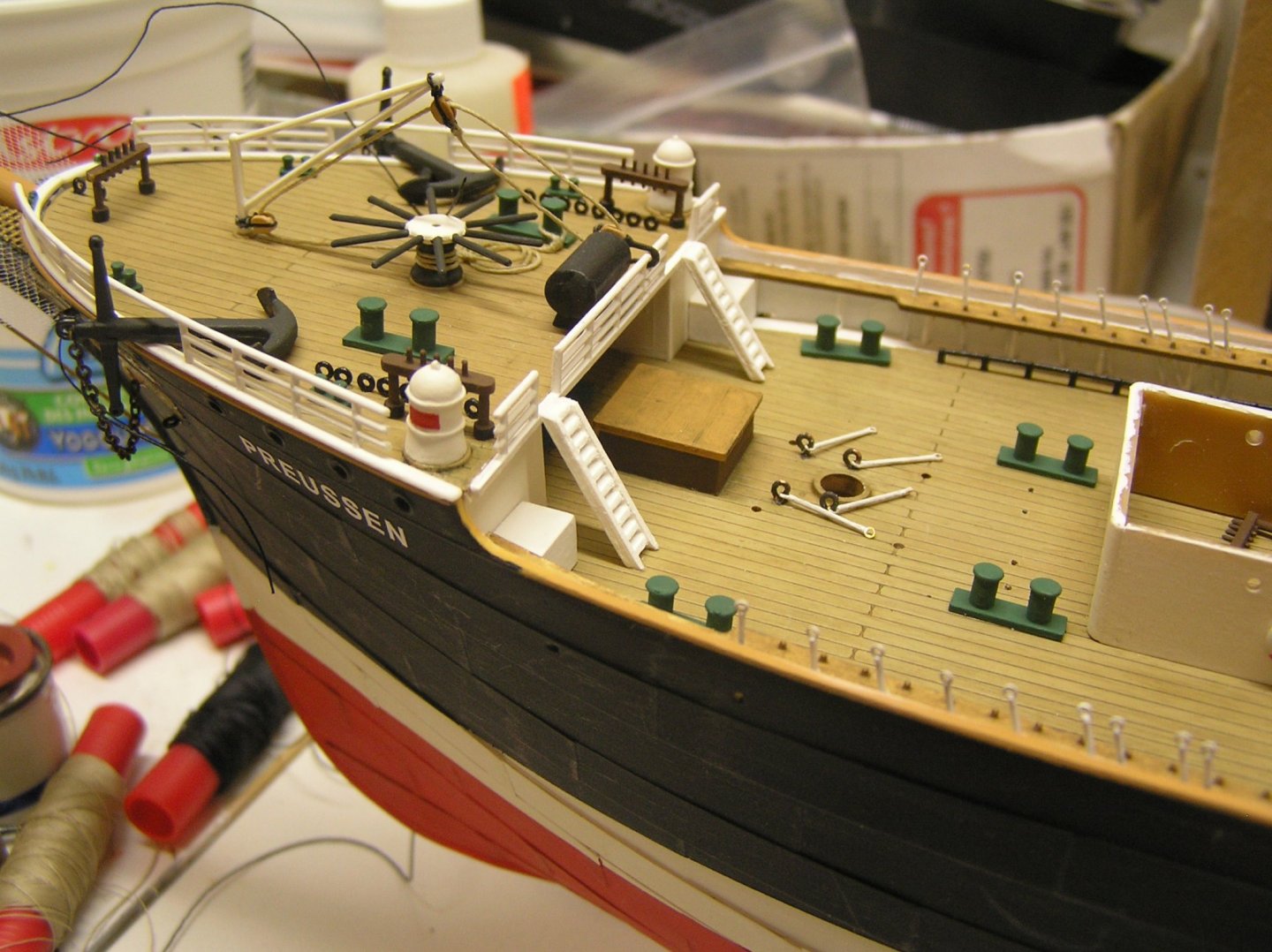
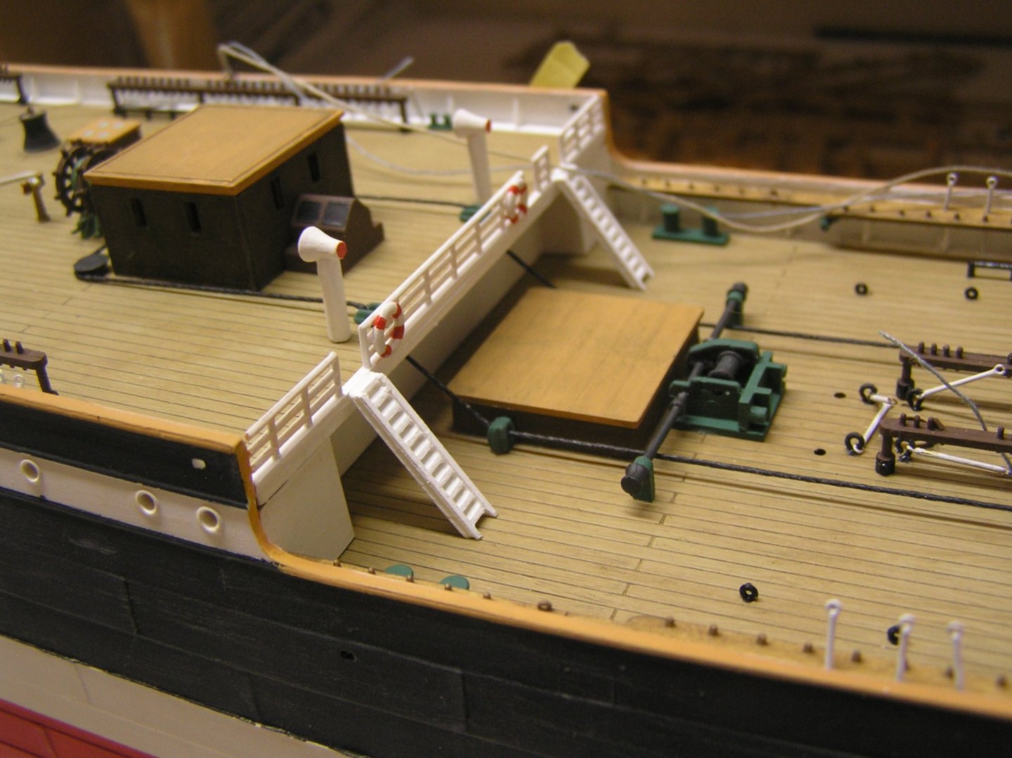
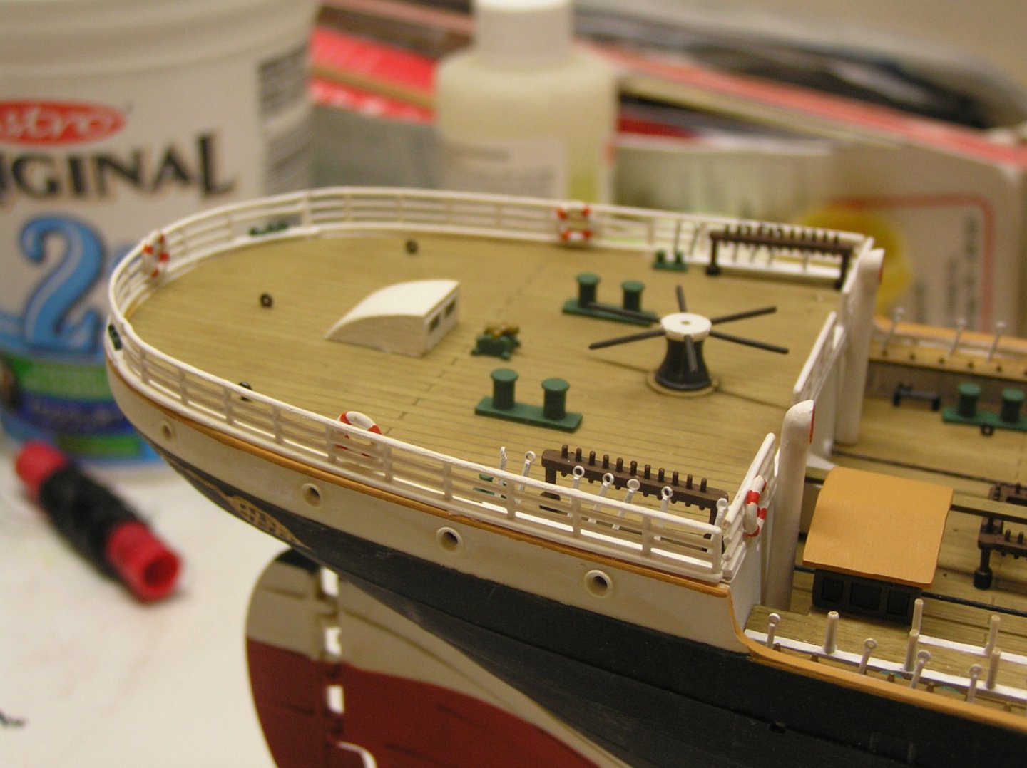
A few new photos. Here are some painted ladder handrails, made of micro brass rod. Here is one of the capstans in its new paint scheme. I wanted to paint a circle on top of the head; tried using a hole punch to put a hole in Tamiya tape to mask a circle but punch was too dull and the tape always tore. It belonged to my mom and maybe her mom too. So then I thought maybe I could use a letter "o" from my adhesive vinyl lettering I used for the gold stern lettering but the letter "o" 's were elliptical not round. But I noticed two different circle sizes were provided on the sheet so I stuck one on this capstan. What do you the viewers think? Better with a plain white head? Oh, I also changed the porthole glasses on the hatches to light blue, instead of the black advised by Heller. I didn't know what they were at the time. Why so many hatches all crammed in one area of the deck? And here are the storm gangways with provided railings attached. Heller advises to string thread along the stanchion tops but I bought some small evergreen half-round moldings to use instead (half round gives me a flat bottom to glue to stanchions). Don't know why they didn't mold the full railing as on the other railings. I forget if I mentioned before that I cut off the weird "bucket-like" projections on the flying bridge and moved the stanchions out a bit. I always wondered what the little hut was at the aft end of the aft gangway, since it overhangs empty space above the well deck. I have just learned while re-reading "The Last Grain Race" that "Moshulu" had a chicken coop just here so I'll go with that.
-
I have a lot of fond memories as a child of playing hide and seek with my brother on HMCS Haida, the last surviving Tribal destroyer which was then (late sixties) moored as a museum ship on the Toronto waterfront. They also had a Lancaster on a pedestal nearby; we used to pester mom and dad to take us down there and bring sandwiches for a picnic. Haven't seen Haida for years, since she was moved to Hamilton harbour for some reason.
-
Nice model! Don't quite get why a block is needed at sternpost when brace blocks are on the yardarm pendants. Since the fixed ends are at the sternpost, if you don't like the hole why not just frap a rope around a few turns like you have done, and its two ends become the two braces? Just another idea.......... 🙂
-
Dave, Love your model, she's looking really good! Just thought I would show what I did about serving rope - made a serving machine from my old meccano which I have held onto for 50 years but my modern kids were never interested 😞. Just needed to buy brass tubing of the correct "meccano diameter" for the hollow shaft. Works well albeit a bit creaky when cranking 🙂
-
Roger, gak, and Popeye, thank you for your positive comments on the build; it's always nice to receive some. No more pictures yet, but I managed to pry the capstans off the decks and am repainting them somewhat like those on Passat but in a simpler form. I cut the bars off most of them and painted red dots where they would insert (tiny squares too hard to paint). I didn't remove the anchor capstan because of the thread already rigged on it but maybe I will change it too, we'll see. The ladder handrails are made but not painted white yet.
-
Love your weathered deck! And the molded detail on this kit is incredible especially given its size. I agree with Backer regarding the gun ports. Will enjoy watching you paint all the statuary; good luck!
-
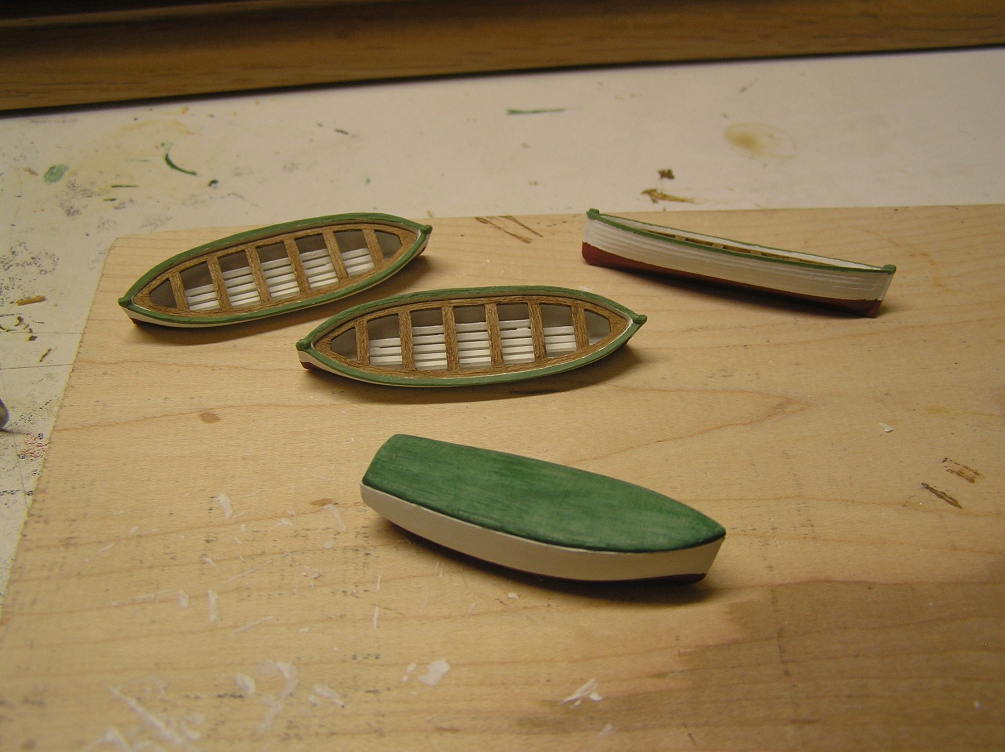
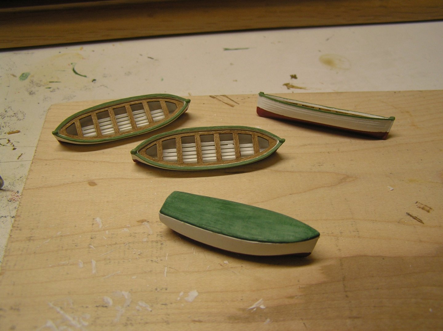
Thanks Roger and "gak". I wondered about those bars. Wouldn't want to be washed into one ribs-first by a wave! I wish I'd done more of a paint job on the capstan bodies; at the time I was following Heller's "everything is drab gunmetal grey" instructions. I guess they were the first things I painted. On the other hand, without them the uninitiated viewer will wonder what all the big grey lumps are. I'll have to decide what to do. In the meantime I received revision 2.0 of the 3D-printed ladders from my brother. He sent forty (!) of them, perhaps in case I want to make Passat and Pamir too! They needed a little tidying up; they're very small with lots of acute angles to print. They are far nicer looking than Heller's ladders, plus their miters are in the right direction :-). I also painted the ship's boats. They had a few internal ribs to support the seats so I just added a few evergreen strips for floorboards. Quick and dirty, I didn't want to spend an inordinate amount of time like on Victory's boats. Speaking of not leaving capstan bars in place, I've seen lots of models with oars tied onto the thwarts of the boats. I didn't think they would leave them out there all the time, but perhaps in case a fast exit is necessary? Wondering whether to add the oars or put them in my parts shoebox.... Here are some photos. I will be adding handrails for the ladders when I get some more micro brass rod.

-
That explains it. I thought the wood itself contained occasional dark patches. Some sort of tropical wood. Second planking looks very good!
-
Hi First planking looks good. Which wood species is that? Also, do you find your aluminum miter box wears on your saw's teeth?
-
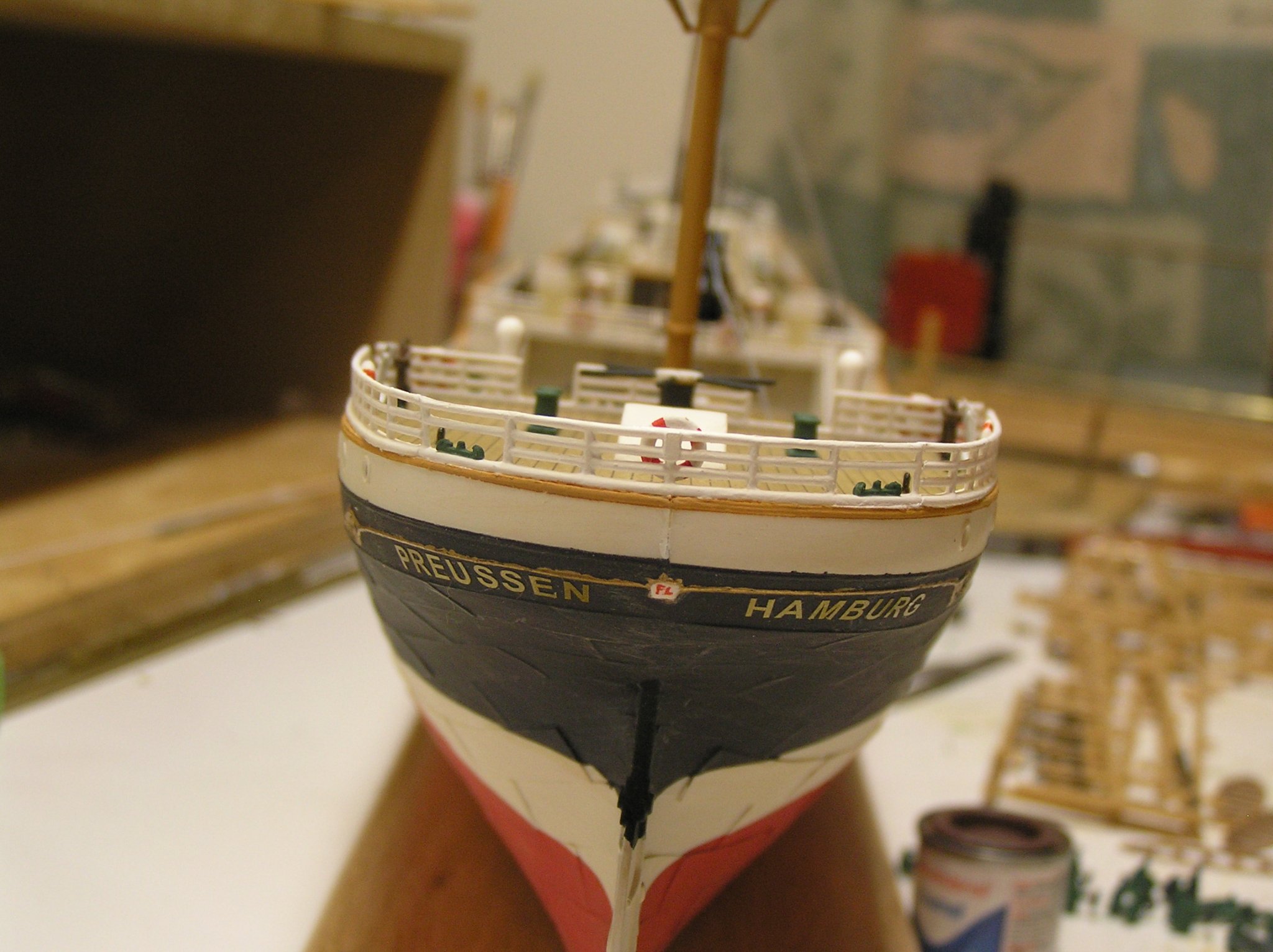
Yes, that's a beautiful Connie! I love his sea and crew. I would have made the sails slightly less stained. I made this kit as a teenager and I just scrapped it recently after finishing the Heller Victory which supplanted the Connie in my affections. I'd love to make it again knowing what I now know as opposed to what I knew in the 80's, but there are too may other things I'd like to do. I did paint and fit my replacement stern railing from glow2be. I've also been busy painting and attaching the stanchions strips along the storm gangways. Why Heller didn't mold full railings like those along the bulwarks is a mystery to me. The situation now is I need thread to be able to go any further, other than that finally I am going to be forced to attempt, reluctantly, to fabricate some brass yard trusses.

-
I don't like the thermoplastic sails that came in the kit, and never having made cloth or silkspan sails I think trying to make 43 is too much. Plus with sails I'd feel obligated to rig all the buntlines etc and at this scale with these tiny blips of belaying pins that's too much for me to face! I have other stuff to do once this ship is finished 🙂 . I'm planning to just tie any lines that come down the masts to the pinrails around the rail as opposed to trying to belay on the pins and hide the cheating with rope coils. By my count there are 126 buntlines on this ship. I'd rather just omit them and the blocks which would be tiny and are not in the kit. I've been looking for thread now that the lockdown is opening up a bit. According to Underhill even the largest steel wire on the standing rigging is 4-1/2" or about 1" diameter which at 1:150 scale is less than 0.25mm. That is almost the smallest thread used on the Heller Victory. I bought some Coats and Clark XP Heavy Duty thread in grey, measuring about 0.25mm. It looks very small but held up against the masts it's ok. This again emphasizes how thin the ratlines would need to be for scale appearance smaller than the shrouds. This thread is a bit fuzzy so I will have to try applying beeswax. I did not have much luck with beeswax on the smaller threads on Victory, though.
-
This comment made me think of Sheldon's "Fun With Flags" blog on "The Big Bang Theory". What a great show that was.
-
Interesting wire, but even the "fine" grade at ten thou is a bit heavy for ratlines at 1:150 scale. I believe Blue Ensign employed fine wire in his "French 74" build. Might end up going that route.
-
Windjammer Wire Rope vs "Natural" Rope??
Ian_Grant replied to Ian_Grant's topic in Masting, rigging and sails
Wow! I was not expecting so many replies so quickly. I figured wire rope wouldn't reach belaying pins to be handled. So in the case of my braces grey thread will run from the winch through the yardarm pendant block then become tan thread to go to deck level, perhaps in a whip. We're just coming out of lockdown again so I'll be able to shop for thread, finally. Thank you to all for your replies. What a great forum! -
I have a query about wire rope employed on big steel windjammers vs (I'll call it) ordinary rope. Would the crew ever handle wire rope manually? Would wire rope ever be belayed to a pin? I ask because, for example, lower brace lines led (at least on non-British ships) from a deck-mounted Jarvis winch through leading blocks to the yard's brace block on its pendant, then back down through bulwark-mounted sister blocks to be tied off at a pin to enable fine tweaking of each yard's brace by hand; albeit pretty rarely I would assume. Was this brace line shackled to plain rope somewhere between the brace block and the bulwark so if handling became necessary at the pin the crew would be dealing with plain rope? I can't find this level of detail in Underhill's ocean carrier rigging book. I do have a Time-Life Seafarers book that mentions the "ends" of wire ropes were attached to ordinary rope where handled by the crew's hands; any one have detailed knowledge? Thanks.
-
Hello! I think you have your work cut out for you! Extending the beakhead, building up the stern, making all the figures we now know she was adorned with, etc. It looks like you planked your deck; I just left it with the inked planking as supplied 😞 . I will enjoy watching your progress. Now to figure out how to "follow" you! I too tried to build this model as a teen in the 70's but didn't get as far as adding wales or cutting gunports. I do remember the lump in the hull; I didn't know about fairing either. Your planking is much better than mine was. I painted some blue on it, as far as I recall. But when I read in the instructions that I was to carve two lions out of the supplied balsa blocks I decided that this model was beyond me. I switched to the Revell 1:96 Cutty Sark and Constitution kits instead. My Wasa hull is long gone, but I still have the fittings kit if anyone is interested.........
-
HAHAHAHA!!!! I think I remember the year you mean, which was before they changed from Victoria weekend to a weekend in mid-late June. My last time was the weekend with 43C humidex on Saturday. It was so bad OBC had to charter a bus to take exhausted people back on Sunday. Sometimes it was delightful cycling, sometimes not. 🙂
-
Very nice job, Bill!! I can't believe how quickly you finished this build. You had said before you were planning to build the Heller Victory, case it, and display it to the left of your man-o-war. Is the plan still the same? Where will you display the Mayflower? At the rate you go, you could cover the wall with ships 😉 I'm late to this party I know but I was very interested in your first post to see the kit deadeyes which had the three holes AND a groove around their periphery. There must be some new molding technology to allow this. You'll find the deadeyes supplied in the Victory kit to be unusable. This older kit's deadeyes have the three holes but just a single raised lip around the periphery since a grooved deadeye would prevent a standard two-part mold from opening cleanly. The lip only prevents the shroud from slipping off in one direction so it's well nigh impossible to tighten the loop and seize it. I've read where some modellers use glue as an aid but please, I urge you to buy some wood deadeyes to save your sanity. The Victory kit already has enough other problems to overcome. By the way, the Victory took me five years as at first I only worked on her in the winter. I'll be interested to see how long she takes you! Best regards, Ian
-
Dear "rookie": Thanks bro. For those unaware, "Rideau Lakes" is an annual double-century Ottawa-Kingston-Ottawa cycle ride with overnight in Queen's University residences on Saturday night organized by the Ottawa Bike Club. I rode it quite a few consecutive years between the mid 80's and mid 90's with bro joining me a couple of times.