Ian_Grant
-
Posts
2,152 -
Joined
-
Last visited
Content Type
Profiles
Forums
Gallery
Events
Everything posted by Ian_Grant
-
 Bill, Nelson's cabin needs a portrait of Lady Hamilton......😉
 -
I've finally realized why "Capt Graham Moore" seemed familiar. In "Hornblower and the Hotspur", Admiral Cornwallis detaches five ships to intercept the Spanish treasure flota under the command of Capt Graham Moore in "Indefatigable". Looking forward to reading about it when my copy of the book arrives. Presume he was the soldier John Moore's brother..........
-
Yes, your main sheet looks good. Your Cutty looks nice. Maybe I should consider trying to clean 40 years of dust off mine and then case it? For the most part it is still intact, some minor repairs required, although I wish I had painted the molded deadeye lanyards. Or perhaps I will build another someday with wood deadeyes. My Constitution is a write-off; for parts only.
-
Three titles so far....... But look at this: https://www.abebooks.com/9781503254336/Frigate-Commander-Supplement-Wareham-Tom-150325433X/plp
-
While searching for this, also came across "Commander" by Stephen Taylor. This is about the real-life Edward Pellew and his exploits in "Indefatigable". Obviously I have not read it, yet, but it seems highly rated.
-
I built both Revell kits way back in the 70's; they're still sitting in the shipyard but very dusty and pirated for parts. I think the Constitution is regarded as the better model of the two; the Cutty Sark has weird issues like the deck caulking lines are proud of the planks not recessed, or the lower mast deadeyes (at least as supplied in my 70's model) are molded with lanyards that span about 8 scale feet !?, or the bow and stern decorations are simple decals with no 3D "presence" (again, at least in my 70's kit). The Constitution is pretty good, except for the yards being just magically glued on to the masts with no parrals or lower yard truss pendants. And both models come with those molded "rubbery" shroud/ratline assemblies which I would not use again personally....
-
Bill, looking good! If the bitts behind the main mast aren't glued, you might want to drill some sheave holes at the base of the uprights in order to rig the three pairs of ropes passing thru the quarterdeck here sensibly. Also, those little pillars are easy to knock off as you slide the quarterdeck into place. If they're not glued already, they're easy to add afterwards, and then you know you're lining them up with the skid beams properly.
-
No that bracket is not provided. You either believe it was there (see Dafi's recent posts here) and make one, or ignore it and put the block just on a long strop to the eyebolt.
-
True, you cannot do better than Longridge. He spells everything out clearly and succinctly, rigging line by rigging line.
-
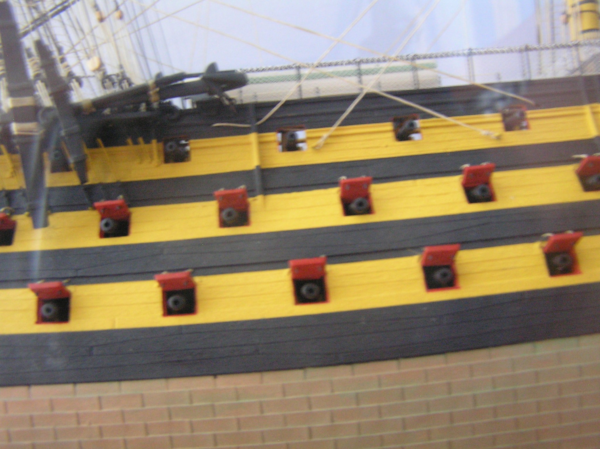
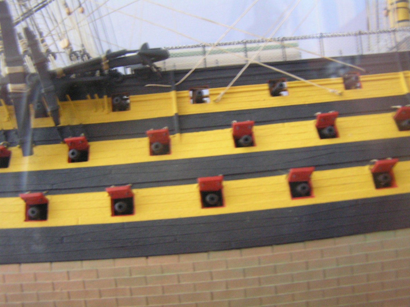
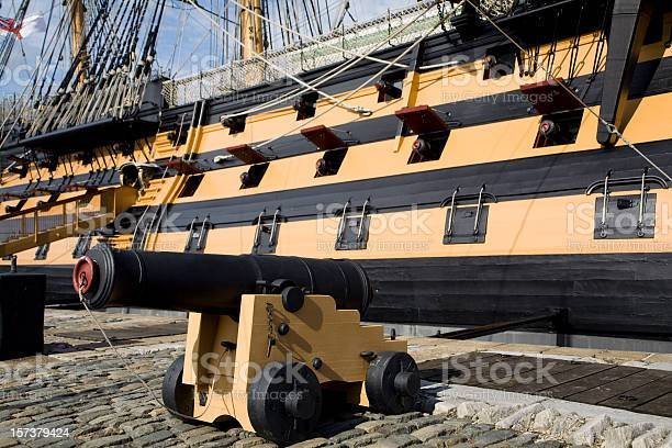
BIll, you have it routed correctly, but to make it easier I would glue in an eyebolt for the standing end of the sheet (as in Longridge's diagram) instead of running this end of the thread through the hull. If you carry on as is, you will need to predict the exact length of thread you need to get the sheet block in the correct location be it with or without sail; if you add an eyebolt you can make the thread longer than needed, store it in a coil dangling from the hull, then when the time comes rig it and tie off the end. EDIT: Sorry, I was away a few days, logged on and saw your original question about the main sheet and answered it without realizing there were all these interim posts. Yes, many of the rectangular holes are for attaching the channels, which hold the lower deadeyes. As for the main tack, after it emerges from the hull just below the big deck chock for the sheet anchor it passes through the sheave hole in the chess tree just aft of it (Longridge pg 252 "Tack"). See below, which shows the main tack and fore sheet crossing each other in this area. Again, I would add eyebolts as shown to make them easy to rig later. On my model: On the 1:1 model:
-
I don't recall butt-joining things like stag horns and bitts onto bulwarks or decks, but I think all the masts and spars lacked guide pins too rather like the cannon barrels. My current Preussen kit has the same lack of "tenons" let's call them. Especially irritating was the tiny dolphin striker which was to be butt joined to the bowsprit; that would never have held. Same with the support stanchions for the boat skid beams. Must be a Heller tradition. On the other hand, though, all the kit parts fit well.
-
Bill, she looks great! I like your weathered deck painting. I seem to recall being at step 9 for several months but you look likely to finish it in days. Remember BEFORE you glue in the quarterdeck that there are not only the lower sheets and tacks to attach to parts 41 & 100 we talked about already, but also lines to tie to part 89 (mainyard jeers, main topsail sheets, mainsail clew garnets; see note near top of pg 267 in Longridge). Regards, Ian
-
Just a thought - did you wash the hull to remove any remaining mold release on its surface?
- 50 replies
-
- 4
-

-

-
- Marie Felling
- tug
- (and 3 more)
-
HMS Victory belaying anomalies
Ian_Grant replied to tedrobinson2000's topic in Masting, rigging and sails
I imagined they would stand on the main deck and access from below the pin, rather than climb over the boats. I wondered where to coil them when I rigged my model; in the end I think I just cut them and moved on.🤔 -
As Marc said, the centre head rail curls around this roundhouse corner and sweeps up to become the cathead support. What you are seeing is normal.
-
HMS Victory belaying anomalies
Ian_Grant replied to tedrobinson2000's topic in Masting, rigging and sails
Ted, great questions! When I did my Victory, I saw a photo of someone's model with the fore jeer falls coiled in tight eliptical turns, and frapped, lying on deck fore-and-aft on each side of the mast between the bitts. I did the same, but I did not coil a realistic amount of thread for the function... Neither did I coil realistic lengths for halyards and cat falls. Don't know how they handled it in reality. Raising anchors is not frequent - could they have long-spliced an extension to the catfall when needed? I don't know. -
Roger, for those hatches I'd be sorely tempted to get some 3D printed parts especially as there are so many of them and the eye would be drawn to any differences between them. You could draw them with all the flanges and gussets in TinkerCAD, which is free and can be learned in a day for such simple shapes. With your .stl file on a memory stick, you could get them printed at any 3D CAD shop assuming you don't have a printer.
-
Bill your copper looks great! Drove over to Lake Superior, a little past Sault Ste Marie. Pitched the tent at Pancake Bay Provincial Park and explored around there and in Lake Superior Provincial Park. Beautiful area; hadn't been up that way since 1992. Lovely lookout views by hiking, and even canoed in Lake Superior off Agawa Rock (waited for a VERY calm day 😉). Later Edit: Forgot to mention that we were amazed at all the trees around Sudbury now - in 1992 hwy 17 bypassing Sudbury was completely barren, bare rock due to 70's acid rain. Great to see nature taking over again, and isn't life tenacious? Sorry to go off topic, but Bill asked! 😁
-
A72 is the main sheet. Pass a thread through the sheave hole in the hull and rig the inboard end to the staghorn on the maindeck bulwark. Then coil the excess outside until needed. You'll need enough thread to go from the sheave, through the block mounted on the hull, up to the main yard if rigging without sails, or to the clew of the mainsail if included, then back down to an eyebolt on the hull. When you do come to rig it, just pass it through the necessary blocks and tie the standing end off at its eyebolt. Again, the Heller instructions are best employed as a spur to make you look up the real answer in Longridge. The best illustration of this particular area is Fig 56 on pg 95. Longridge has the mainsheet block rigged with a little bracket; there are existing photos of the block just attached to an eyebolt. Take your pick; I made a little bracket just because it seemed better than the block banging against the hull.
-
No, just drill and glue in the eyebolts and rig the shrouds later. The lines you do need to add before you glue in the quarterdeck are the main sheet and tack, and the fore sheet (A72, A74, and A125 respectively on Heller pg 6). These all attach to staghorns on the maindeck bulwarks, part no. 41 and 100 (see heller pg 7). These lines should be passed through the holes in the hull, coiled on the staghorns, and the excess left coiled outside the hull until needed (years in my case, probably months in yours 😁). But you have a ways to go before you need to worry about them.
-
Bill, I made a mistake in my earlier message; had just completed a 12 hour drive back from a camping trip. Where I mentioned bobstays I meant shrouds, corrected in red above. Sorry for the confusion! I believe E50 is a Hellerism. They probably thought there should be the same number of shrouds as bobstays, however Figure 118 shows there is no shroud pair at the outer bobstay. Model on!
-
Bill; yes, plate 71 is not too helpful. But plate 74 shows the two starboard shrouds emanating from the hull eyebolt(s) just behind the lower edge of the cheek, below/ahead of the first lower deck gunport. You can just see the lines heading up to the right, towards the bowsprit. Note that text on pg 226 says two eyebolts for the two shrouds but this picture seems to show both hooked to a single eyebolt. That's what I did. It's too dark in this image to see what happens at their other ends. Fig 118 pg 187 shows the two hearts on the side of the bowsprit to which the bobstays attach. As the text pg 226 states, each bobstay has a heart on its end, these hearts being lashed to the bowsprit hearts with several turns.
-
That's true - with high thrust I could shorten the loom of the oars and achieve a full sweep in less distance hence less time. Might need carbon fiber oars though, to handle the stress point at the thole....😁 The US$100 linear 3050 moves 1.2" in 1 second with 6.8 lbs thrust. That's about what I'd like to achieve as a highest "ramming speed" sweep time. I could set the loom length such that 1.2" gives the full sweep. As a bonus, shorter looms reduces internal width of machinery which increases space for the battery and ballast along the keel. On the other hand a CDN$60 Futaba FUTS3305 dual ball-bearing high torque servo provides 7.7 lb-in and moves in half the time. Not that I need any faster, but assuming I get 120 degrees out of the servo a 0.7" arm would give me 1.2" of sweep at 11 lbs thrust. Some study required to find the best solution........🤔
- 536 replies
-
- 2
-
-
- Quadrireme
- radio
- (and 1 more)
-
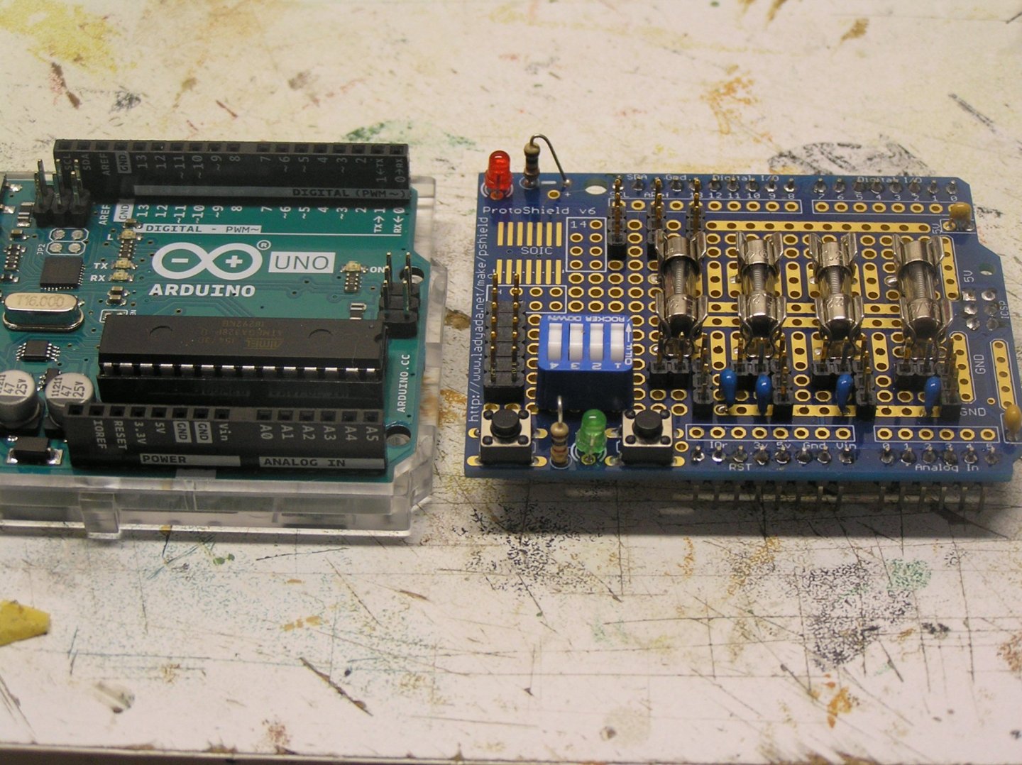
Some slight progress to report: Components received from Digikey and soldered onto Arduino daughter board. It took me a while to find a layout which best takes advantage of the copper connections on the board. I included four fuses to protect the oar servos; optional jumpers to bypass each fuse (for the demo jig if not the actual ship); a quad DIP switch for future contingencies; a little decoupling for each servo supply. The large DIP header is for battery supply for servos, which is independent of the Arduino +5V rail. A 9V battery will supply the pittance of current required by the Arduino (which regulates down to +5V) as well as the RC Receiver, via its servo connection wires to the Arduino. I have not yet soldered hook-up wire to make the connections; that will have to be after we return from camping up by Lake Superior next week.
- 536 replies
-
- 5
-
-
- Quadrireme
- radio
- (and 1 more)