HOLIDAY DONATION DRIVE - SUPPORT MSW - DO YOUR PART TO KEEP THIS GREAT FORUM GOING! (Only 13 donations so far - C'mon guys!)
×


Ian_Grant
-
Posts
2,113 -
Joined
-
Last visited
Content Type
Profiles
Forums
Gallery
Events
Everything posted by Ian_Grant
-

Albatros by Al72 - OcCre - 1:100
Ian_Grant replied to Al72's topic in - Kit build logs for subjects built from 1801 - 1850
Lovely model! -
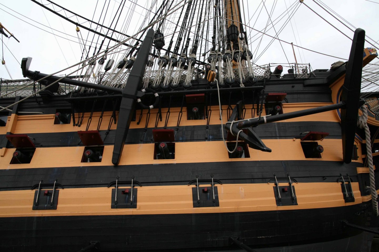
Bill, the above shot reminds me that while you wait for stuff to arrive, you could also consider moving the anchor support block from its erroneous position between the 1st and 2nd fore chains, to between the 2nd and 3rd. A bit odd to me, with correct placing right above a gun port, not really where you want an anchor dangling down??!!, but there it is.... Its Heller location is too close to the cathead with the result that with the anchor fluke in the slot, the anchor ring is forward of the cathead which looks awkward given that it's supposed to be a very heavy object slung by the cat tackle, or however you choose to rig the anchors, when you get there. Longridge shows it in the correct location, Figure 57 pg 96 in my edition. I believe Daniel scraped the old one away and fashioned a new one, somewhere in his build log. Here it is on the 1:1 ship....... Or you could I suppose shorten the anchor shank a tad. I did not know this until I was rigging the anchors, far too late to contemplate taking a file to it.
-
Bill, I've been away at the cottage for a while. Nice work on the guns, and you'll find Longridge an essential companion. I don't know how many times I read through the rigging chapters. E50-55: These are where Heller claims the bowsprit shrouds attach to the hull. They want you to pre-attach the thread ends through the non-existent holes, for later use. Heller's way of doing rigging "instruction" is to give the two ends of a rope the same label, on whatever pages the ends appear. If you look at Step 11 of the instructions ("Fitting the Bows") you'll see E50-55 attaching to hearts used to tighten up the bowsprit shrouds. Now that you know this, forget it. They got it wrong; perhaps why the holes are absent...........and forget about the Heller instructions for any and all rigging. Longridge describes these shrouds succinctly on pg 226 (my 1972 edition) "Bowsprit Shrouds". There are many places on this model where you are best to drill a hole and glue in an eye. But plastic eyes can break and lead to heartache as you know. You can either make your own, or buy copper eyes which are almost exactly the same size as Heller's plastic ones. https://www.cornwallmodelboats.co.uk/acatalog/4703-Eyepin-Copper-2mm--100--A4703.html#SID=367
-
Beautiful area. And I recognize your dog from previous postings.
- 185 replies
-
- 2
-

-
- queen anne barge
- Syren Ship Model Company
- (and 1 more)
-
For the gun decks I just rigged one continuous thread along all the guns on a side as breech ropes, glued to deck between guns. This just to ensure that if you hit a protruding muzzle you don't lose a loose cannon into the hull. But it's your model and your choice what to do in terms of hidden detail.
-
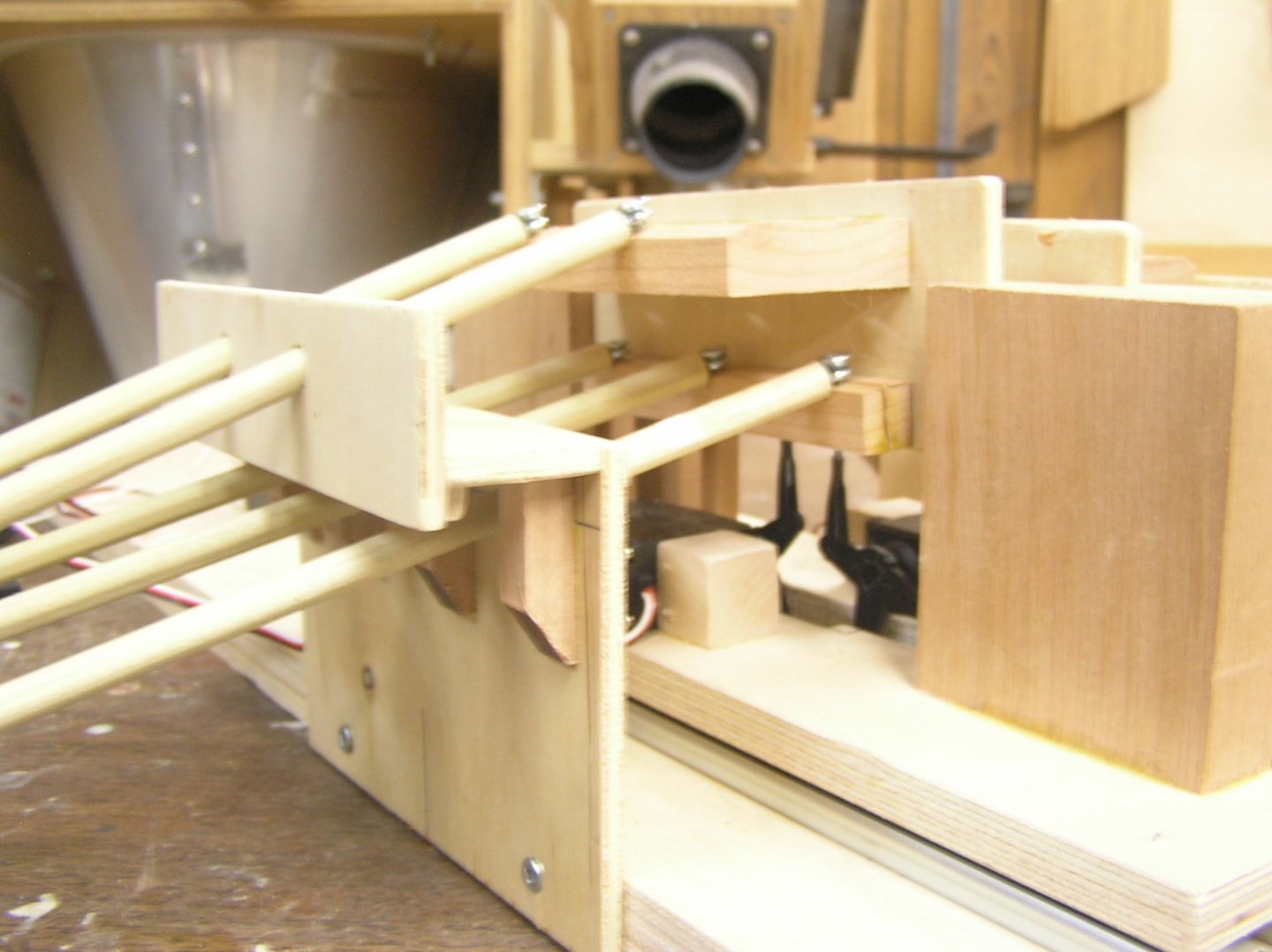
I've already learned how critical the geometry is, just from building this jig. I drew a scale diagram but I'll need to be even more careful next time. This jig does not have the upper oars at quite a steep enough angle for their blades to reach the same presumptive waterline as the lower oars. In an actual model I would put a servo at each end of each beam, connected on a Y-harness, for the up/down drive. A servo in the middle works well enough for the jig. Also, I did not get the full extent of the sweep I planned for because my servos move less than 90 degrees overall at least with my ancient 75 MHz setup. I do have a newer 2.4 GHz transmitter, but no receiver as it was built into my ARF airplane. The big question is: how much power is actually required on the sweep to move a model. This jig just uses standard futaba servos. Would they be enough to overcome the resistance of the hull's skin against the water? Don't really know, might need a giant scale servo or maybe just a standard sail-arm servo. With only servo drive the boat cannot be too large. I'd love to build a sextere with its two archery towers but this is a broad, deep ship whose model would probably need a lot of ballast to load to waterline. That would be a lot of inertia to overcome. The jig as built requires a beam at the waterline of 7 inches. I figure I could lose 1/2" overall off the oar beams by changing the mounting of the lower oars. This jig has oar looms of 2.5"; if I could reduce that without overloading the servos that would reduce the ship's beam too, perhaps significantly. A quadrireme at 1/32 scale would have waterline beam 6.75" (9" overall) and length about 4'-6", draft 1.7" which sounds reasonable. A sextere at 1/48 scale would have waterline beam 8" (8-1/2" overall) and length about 3'-10", draft 2.1" which might be a lot of displacement to ballast. Most of the hull amidships would be the "engine room" filled with the moving oar beams and oar looms. There could be no lateral hull bracing in this area. Further, any deck beams will have to be removable to allow "engine" repairs and maintenance. I'm assuming I could fit batteries, receiver, arduino near the stem, and rudder servo at the stern of course. Note that I haven't built an RC boat in 40 years, or skinned a hull in individual planks in, well, ever! And plans for these ships are non-existent. Pitassi gives the engine room cross section, and top views of deck outline and waterline, but that's about it. Would have to merge Olympias's stem and stern onto this, somehow. Lots to think about.
- 536 replies
-
- 2
-
-
- Quadrireme
- radio
- (and 1 more)
-
They look nice Bill! In reality, though, only the gun muzzles will be seen, with the fronts of the carriages barely visible. I wouldn't worry about painting the trucks etc.
-
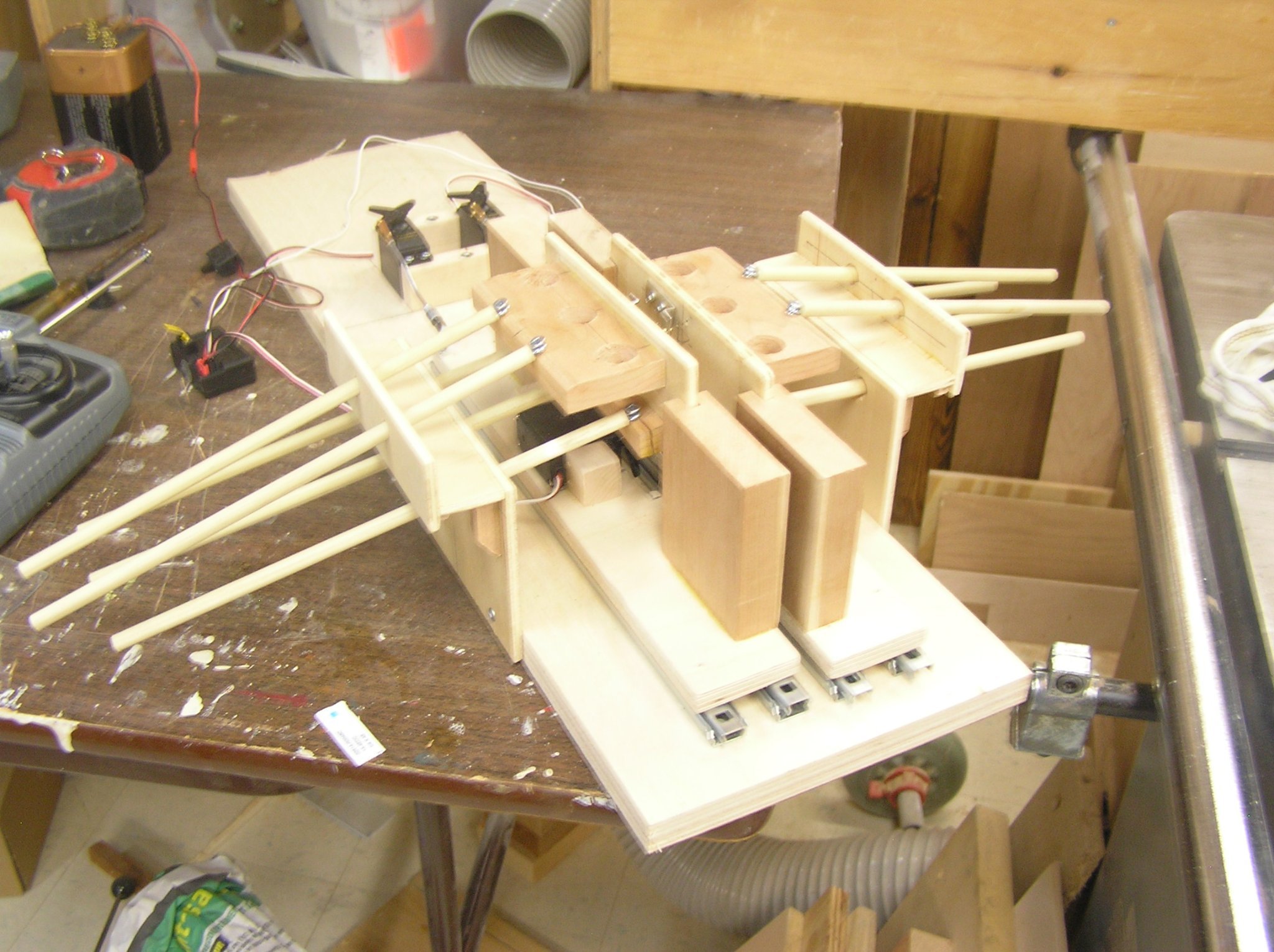
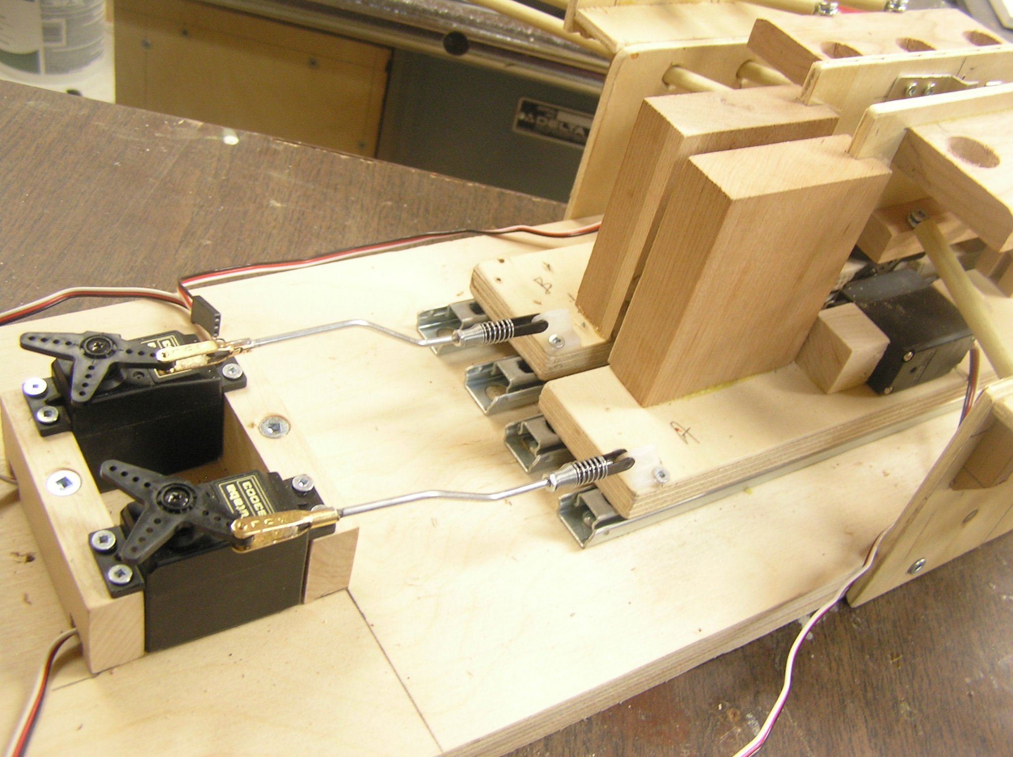
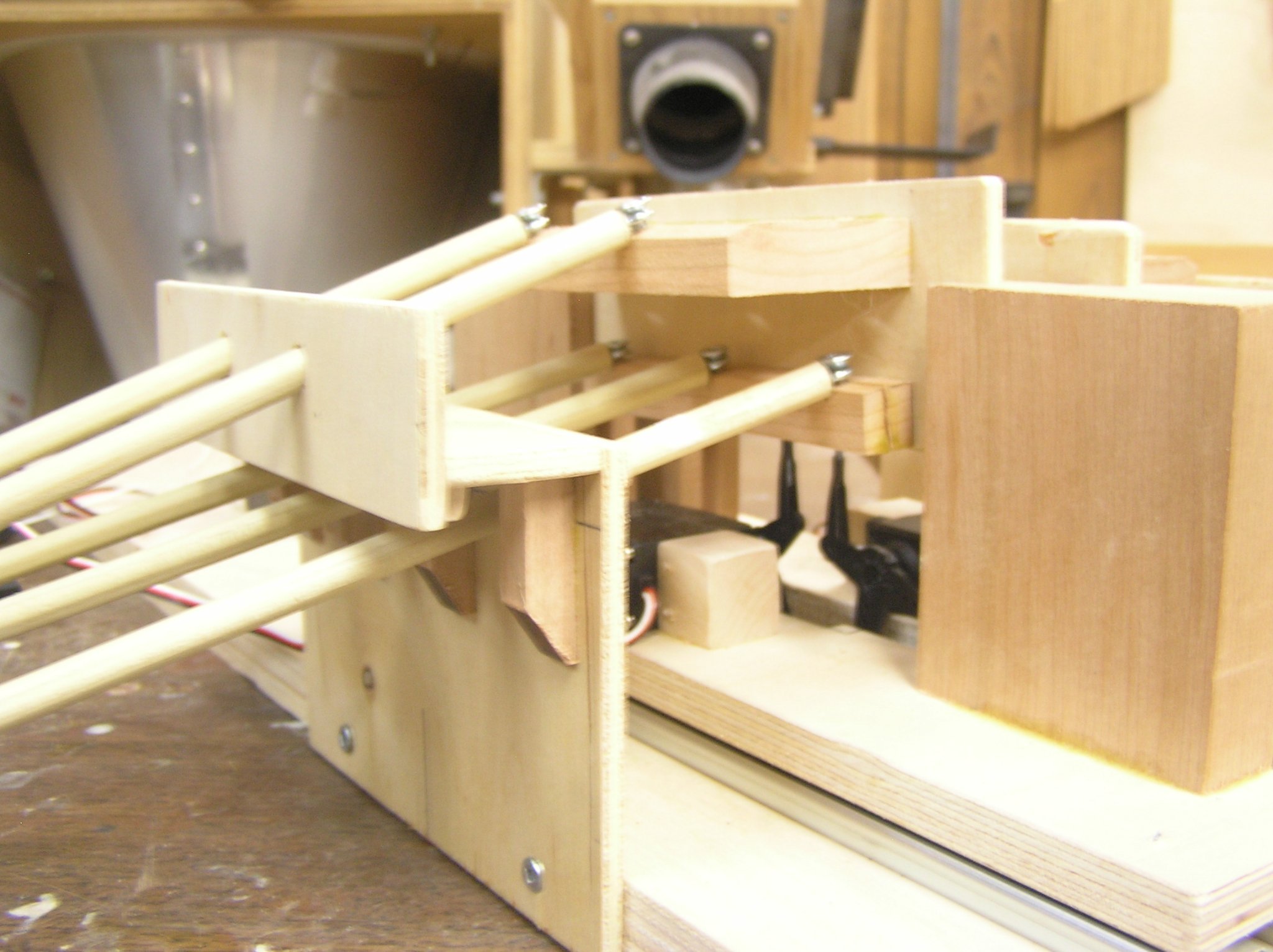
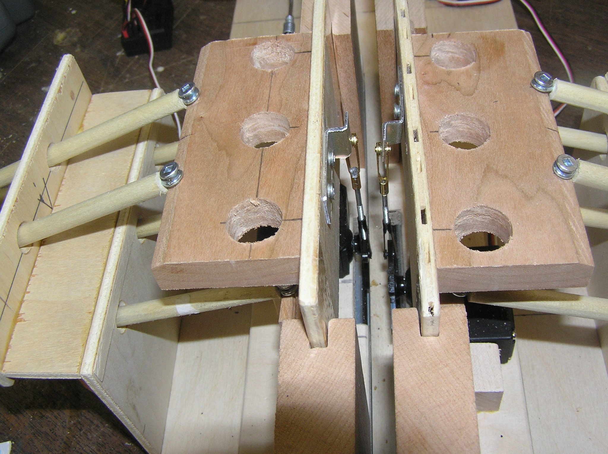
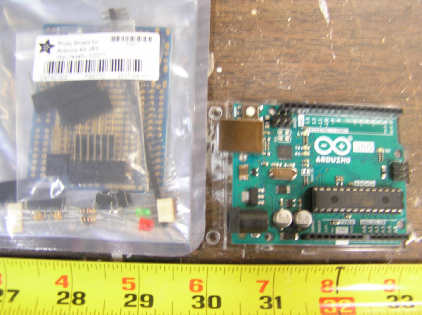
IMPORTANT NOTE: This build log is a title change from the previous title "Arduino Rowing Mechanism for RC Galley". The log was originally opened to record my progress on making a servo-driven mechanism to move banks of oars in a realistic manner, for the purposes of building an RC Roman galley, propelled by her oars, at 1/32 scale. An Arduino "Uno" interfaces to the RC Rcvr and four servos which drive the oars on two sides, with author-written software to control the oars according to the "throttle" and "rudder" signals from the Rc Transmitter. Software was developed using the Arduino "Integrated Development Environment" (IDE) and a prototype test jig containing several oars per side. The log got pretty long in the end; readers interested only in the actual ship development should jump to post 164 on pg 6, bypassing the tangled history of the software and rowing mechanism development. Those who might be interested can read the initial pages. *************************************************************************************************************************************** *************************************************************************************************************************************** START OF ORIGINAL BUILD LOG: Lately I have become interested in ancient Greek and Roman galleys, and have been toying with the idea of making one for RC. When I saw Richard Braithwaite's demo mechanism I became even more intrigued with the idea. As opposed to using electric motor(s) and some sort of mechanical drive with pulleys and chains I thought a better way might be to use hobby servos for the job; one servo driving the forward/backward sweep and a second driving the up/down motion of the oar loom beam (per side). And rather than having a four channel set and continuously twiddling the sticks to make the oars row, it seems an ideal application for an Arduino microcontroller running custom software. In this scheme, the Receiver output servo signals for "throttle" and "rudder" are connected directly to, and read by, the Arduino. The rudder signal is also connected to the rudder servo via a y-harness. Arduino software controls the four oar drive servos. This servo-driven scheme has several advantages over electric motor mechanical drive: (1) Since software is driving all four servos, it is simple to keep them all moving in sync, whether going forward, backward, or reversing oars on one side during a turn, at any given speed, (2) Software can use the "rudder" input to decide when to move the two sides differently; for example a slight course correction can be ignored (by the oar servos); a middling rudder angle could halt the oars in the water on the inside of the turn; a large rudder angle could reverse the oars on the inside of the turn (while keeping the start and end of the stroke synchronized on both sides). (3) When slow speed is desired, the software can shorten the stroke as opposed to an electric motor drive which still executes a full stroke making it look like the oarsmen are stretching right out and pulling back, all in slow motion. (4) Software can provide a slight pause at the end of each power and return stroke, as would occur naturally as the oarsmen absorb then reverse the inertia of the oars. (5) Software can make the return portion of the stroke faster than the power portion to better represent actual rowing. The shape of the overall stroke is formed by the dynamic relative movements of the sweep and lift servos; any shape can be formed, eg rectangular, oval, eliptical, circular, by performing a bit of math in software to calculate the next servo position writes. In short, the oars can be made to do whatever one wants, and is capable of writing code for. I decided to build a test jig for code development. Each side of the jig has 5 oars in a bireme arrangement; I'm thinking of making either a Quadrireme (88 oars in two remes of 22 each side), or a sextere (120 oars in two remes of 30 each side). See Michael Pitassi's book "Roman Warships". Here are a few photos....... Each side's "platform" slides on two Slim-Line drawer slides which only occupy 3/8" of vertical space. Much less than ServoCity's X-beam with mini rollers etc which was my first idea. The vertical chunks of wood at the platform ends are dadoed to let the oar beam slide up and down; the ends of the oar beams I wrapped in packing tape to make them "slippery". In an actual model I'd replace these with ServoCity's SS shafts and linear bearings. The dummy oars pass through a "hull section" which defines the spacing between the two remes' "tholes". Here we see the two servos which drive the platforms back and forth. Here we can just see the two servos which drive the oar beams up and down. Here is the Arduino board, and a prototyping board which will be mounted on it and contain connectors for the receiver inputs, servo outputs, etc. My simple two-channel RC set can only drive one side right now, without the Arduino. Tried to upload a video but no joy; will try again later.


- 536 replies
-
- 7
-
-
- Quadrireme
- radio
- (and 1 more)
-
I remembered one other thing for the "not necessary but nice" category is to make two "fish davits" (not supplied) and stow on forecastle. Basically just two square timbers with some beveling. I agree with Marc - it's a slippery slope once you start improving the model.
-
Bill I guess the short answer is "it depends". It depends on what level of detail you would be satisfied with given the required effort. From the look of your other ships I know you can easily complete the Victory. It must be overwhelming having us throw information at you, but know that this kit makes an incredible model. I would say the minimum "bashing" requirement is trashing the supplied blocks and deadeyes, buying more sizes of thread in black and natural, improving the lower chains and the stanchions, thickening the port linings, attaching the yards properly, and adding the "saddle" (another Heller "oopsie") to the mizzen mast to support the driver boom. The hull, guns, decks, masts, and spars are very detailed and accurate. There are many other little changes you can make for further enhancement. Some of the physical mods I made include Daniel's binnacle (which you are getting), Daniel's boarding pike racks (ditto), Daniel's skylight (ditto), poop deck ladder handrails, buying and adding scale stream and kedge anchors, opening up one of the stern flag lockers. You can also spend much time adding the missing internal framing to the ship's boats which really significantly improves them. For those really into extra detail, the poop skylight is slightly too far forward and could be shifted, the bower anchor shoes should be between the 2nd and 3rd chains not the 1st and 2nd, the Prince of Wales feathers on the stern are wrong, the deck plank shift pattern is wrong. I did nothing about any of these, though I would have moved the anchor shoes had I known before it was too late and risky. Once you are armed with Longridge, the rigging is do-able. You need to plan it well though. I omitted all staysail rigging and all slab lines and signal halyards. You could reasonably omit all bowlines too if rigging without sails; I rigged them anyway and hitched them to the yards. I did add anchor buoys at the fore shrouds. I also added fore and main royal yards (not supplied) stowed lashed inside the topmast shrouds, and fore lower stunsail booms (not supplied) stored on the skid beams. I hope this shows you the scope we are talking about. You can choose how obsessive to be about the job.
-
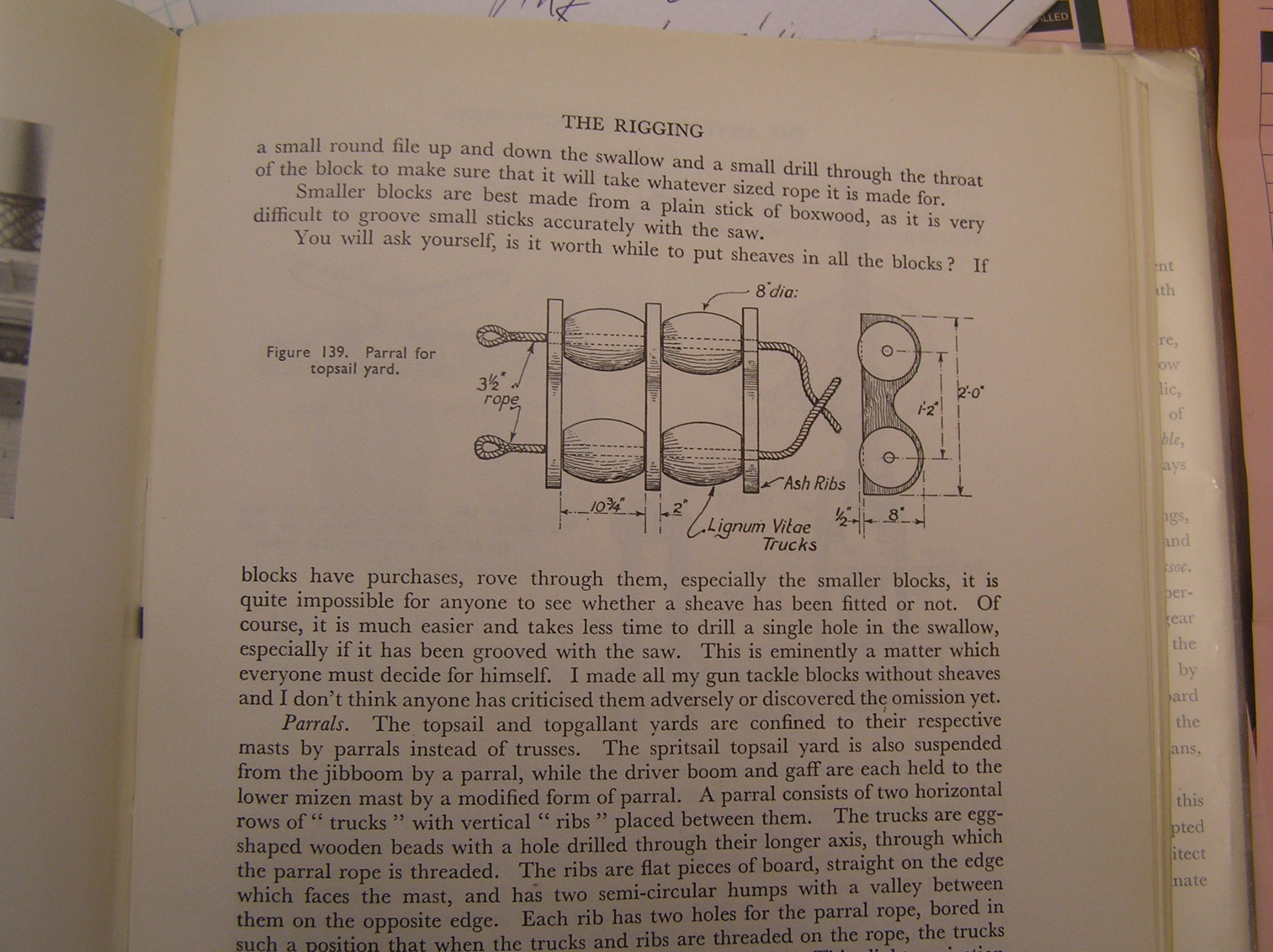
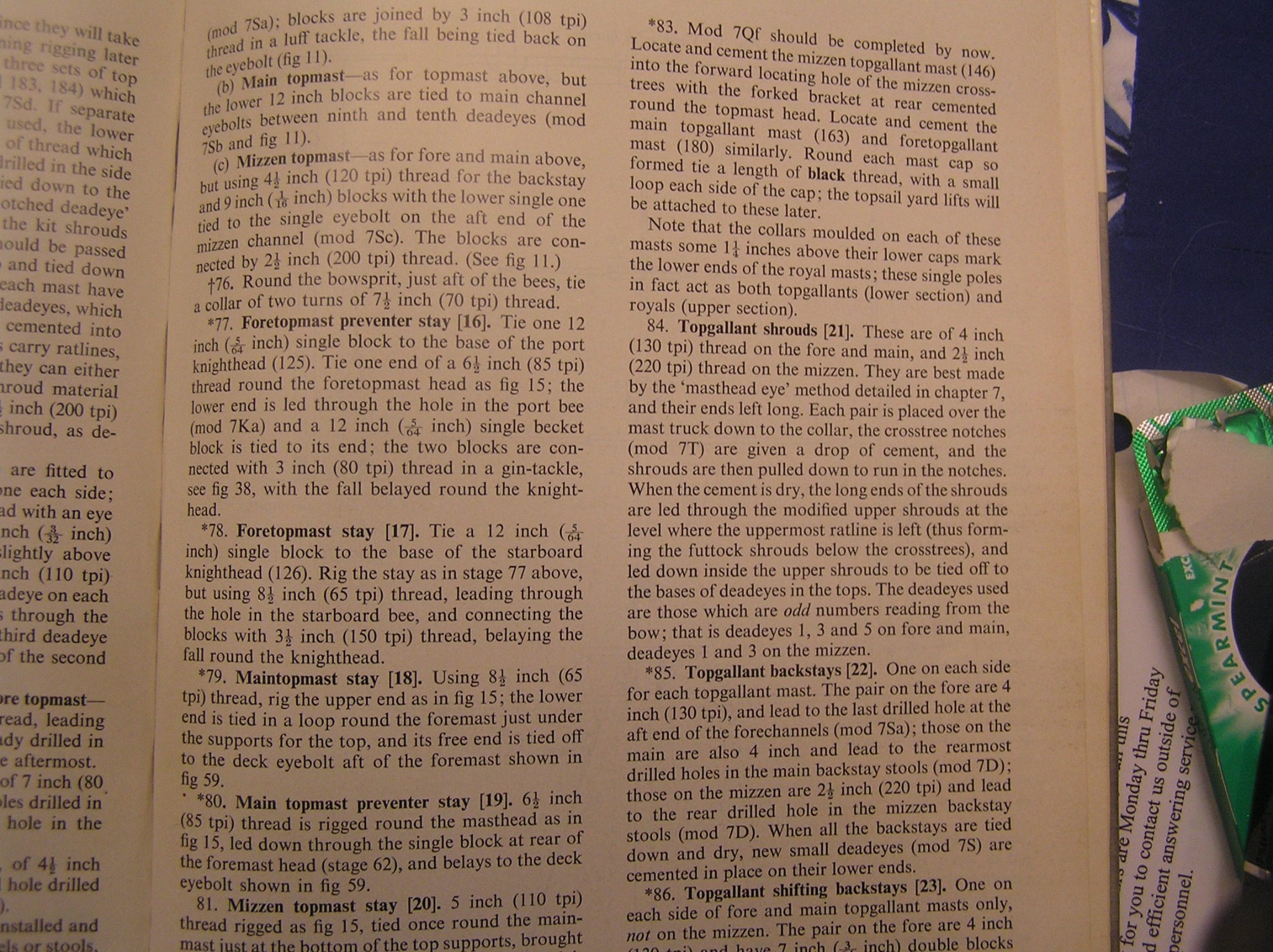
Yes, that's the one. I should mention that of its 272 pages, the detailed rigging description occupies about 70 pages; the rest deals with scratching a wooden hull and fittings and is very little use to the plastic modeller. There is a much smaller book, "Classic Ships: HMS Victory" by Noel Hackney, which demonstrates how to enhance the smaller Airfix Victory. It goes through all the same rigging stuff with rope and block sizes but has far less detailed diagrams, though adequate. If you are budget conscious I assume this little book would be far cheaper and you still have MSW to assist. For your other question, the truth is that, going by build logs I have seen, most people who start this kit never finish. You have to be pretty dogged to overcome the terrible instructions and know to buy wood blocks and deadeyes. I actually bought my kit in 1983 but life got busy and it was started only a few years ago after my kids got big. Had I started it then, without the internet and its invaluable search tools and forums, I probably would not have finished, or at least it would not have been near as nice. Remember the days when all you had was a local hobby shop (there were good ones) and looking at the ads in "Model Boat" magazine for materials? 😀 How would I ever have learned of Longridge's book? Regarding parrals, here is a pic from Longridge. I just bought some seed beads of appropriate size, filed a piece of maple to the cross section, drilled, then sliced it up with an exacto knife. Then sort through the pieces for the best. And for example here is a page from Hackney's book. Short and sweet. His scale block sizes are for the smaller Airfix model, not for 1/100 but you can convert his actual size to suit.

-
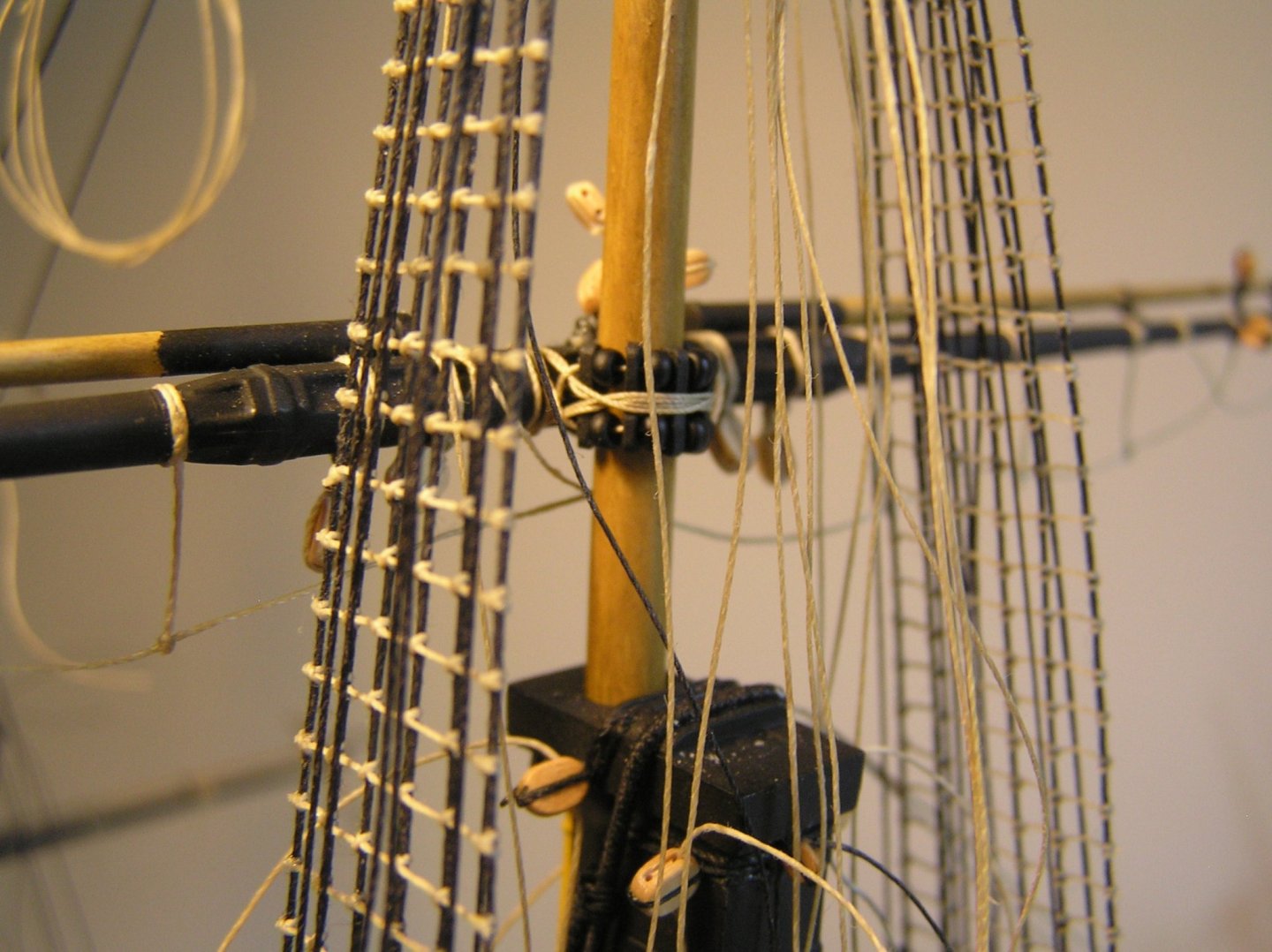
Bill here is an example of a parral made with seed beads and some tiny slivers of wood, drilled. It's relatively easy to rig the parral with the brass rod retaining the yard in place.
-
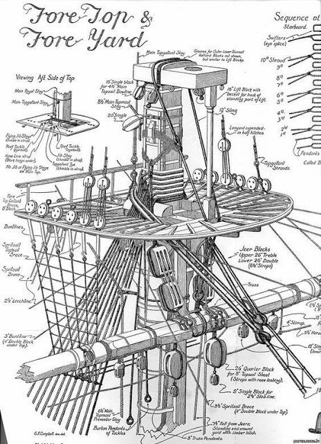
Yes that picture is during my build. You mean the gun rigging? I left off the steady tackles to the deck rings; the rest is pretty standard but I cheated and just attached the breeching rope and train tackles to a single pair of eyelets beside the gunports (now that I think of it, these holes for the eyelets are best drilled before you glue the hull halves. And even before your final exterior paint in case you accidentally drill through 😉. OC is right about increasing mast stiffness. In my case, though, I used wood dowels, but a bicycle spoke inside the mizzen mast because the cavity was a small diameter for a piece of wood. It worked great but got in the way when I drilled a hole in the front of the mast for a piece of brass rod to hold the cro'jack yard while I rigged it. I didn't have any issues with the plastic spars. I planned to make a new flying jib boom from a bamboo skewer but in the end used the plastic part. It is cased after all. Glad you mentioned attaching yards to masts. Wood or plastic, Heller provides no means of doing it. I planned to mention this much later in your build, but to summarize: (1) The lower yards are attached by "truss pendants" (and supported by jeers and sling) which you can find out about in books. However, you'll need to add some eyebolts with attached blocks to the quarterdeck at the foot of each mast and you need to add a couple of cleats to the front of each mast; all this to rig the pendants which Heller ignored. (2) the other yards are attached by "parrals" which you probably already know about from your other ship models.Again, Heller ignores them. You can make them from seed beads later. In my case I drilled and attached short brass rods at the centre of all yards, which were inserted into holes drilled in the masts. I did not glue them to the masts, to allow them to give a little if I bumped them while rigging. The rods hold the yards while you rig their parrals or whatever, and are invisible afterward. Again I emphasize - obtain a copy of Longridge's book which goes into great detail on all specifics of Victory's rigging 🙂. To whet your appetite, here is one of the many fine (and helpful) drawings in it (shroud sequence partially cut off):
-
Yes, that's it. Thanks for the stroll through memory lane😀. If you can drill large enough for the breeching thread then great! Not sure how it would look. It might be worthwhile to add eyes for the show guns. I've lost the pics from early in my build, but here is about the best I have showing the main deck guns with the rather neat attached eyes for breeching rings.

-
Bill, you're giving me nightmares by having me re-read my crumbling Victory instructions 🤪. Sorry I don't know what this refers to either. I made zero use of their "Table of Threads" as I rigged by a book. In any case, I believe the breeching rope was 6-3/4" on an upper deck 12 pounder which translates pretty close to 0.5mm DIA thread. The gun tackles on a 12 pounder were 2-1/2" which translates to 0.2mm. I think I used 0.25mm as 0.1 looked flimsy. With care, 0.25mm can be rigged through Syren 2mm wood blocks. And this reminds me: Many modellers, including me, filed off the "flash" on the gun pommels only to later realize that the "flash" was meant to represent the breeching ring. Popular consensus was to file off the flash and add breeching rings using small eyelets, at least for the show guns.
-
Query: How do I click in Daniel's message above to read more about these Turner drawings? No matter where I click I end up at post #1 with the sun burning? Too many pages to scroll through........ Sounds like my Vic might be out of date now after only a few years - no pink in the bee lines and no solid bulwarks 😒
-
Bill, you could do that but Evergreen does make sizes close to what you need. https://evergreenscalemodels.com/collections/14-white-polystrene-strips/products/122-020-x-040 and to save you the trouble of gluing three rows on the bottom: https://evergreenscalemodels.com/collections/14-white-polystrene-strips/products/126-020-x-125 Might be worth looking around for.
-
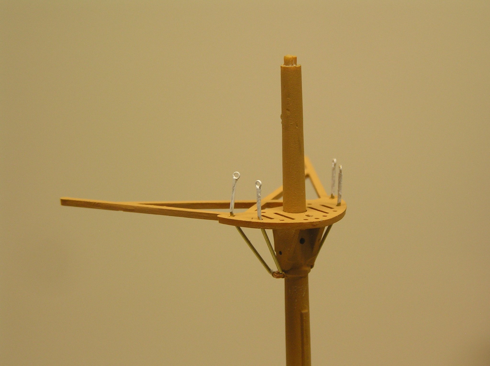
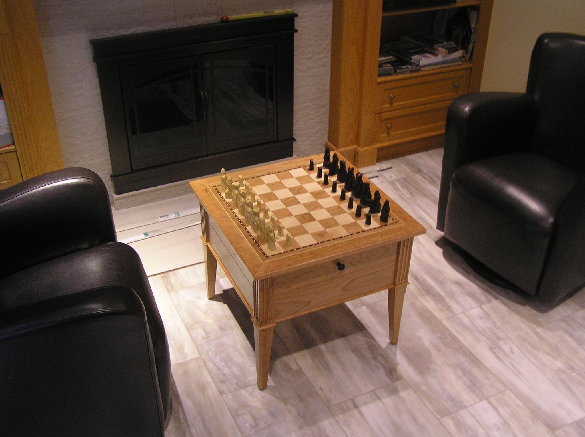
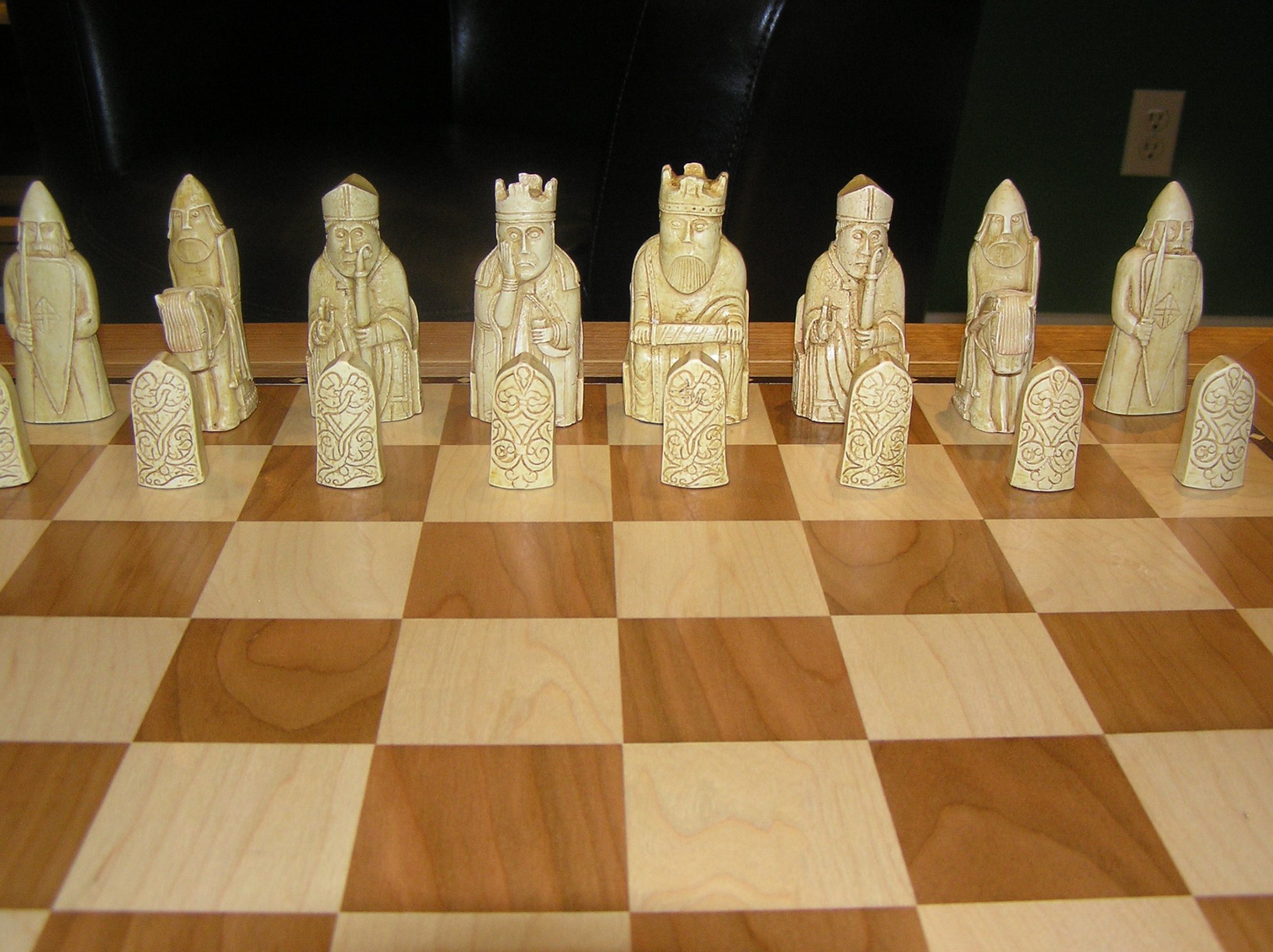
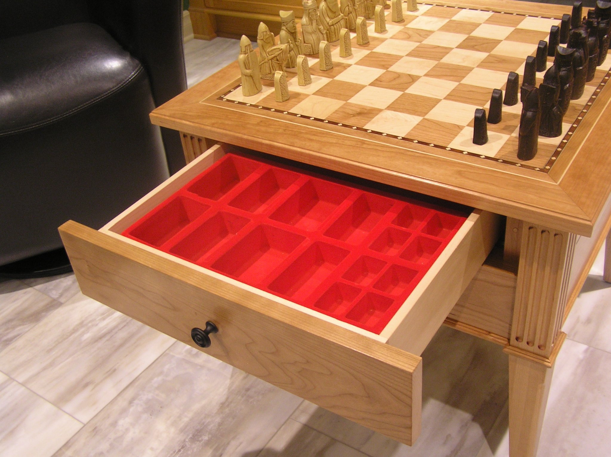
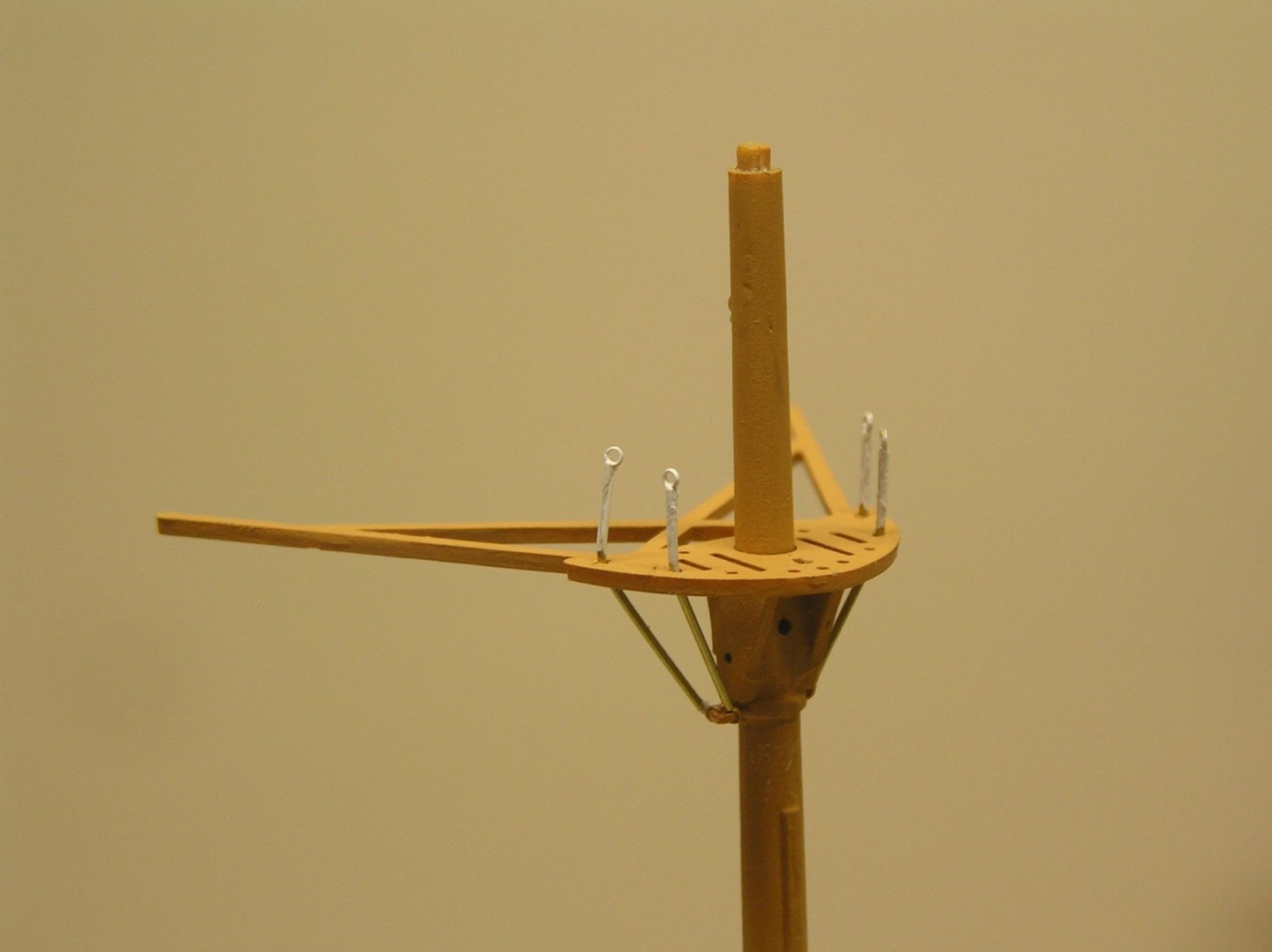
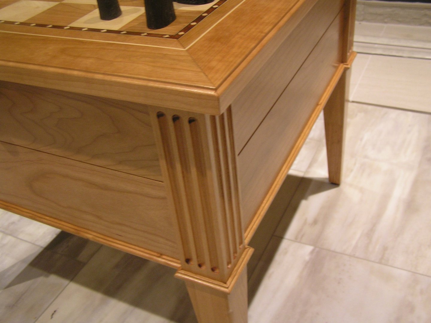
I finished the chess table and even got a little work done on Preussen. I discovered the danger of being away from a model for a while. I was adding the futtock bars at the crosstrees and while working on the fourth mast I realized I was using the wrong two holes in the crosstrees.....what was I thinking?! I had to cut them all off and do again, wasting some precious micro tubing and eyes. Here is one of the masts, with primer on the topgallant shroud "screws": I will now start working on the test jig and program for a galley rowing mechanism. For those who may be interested, here is the completed chess table: The drawers were sized to accommodate the red flocked chess men holders from the original packaging. The field squares are 2-1/4" to suit the rather large men (and woman). The small lower trim was a bit fiddly round the legs, but it gave me an excuse to add a 23ga pinner to my tools ; my 18ga nailer would have made a mess of it. The chess set is a replica of the "Isle of Lewis" set as seen in the British Museum.


-
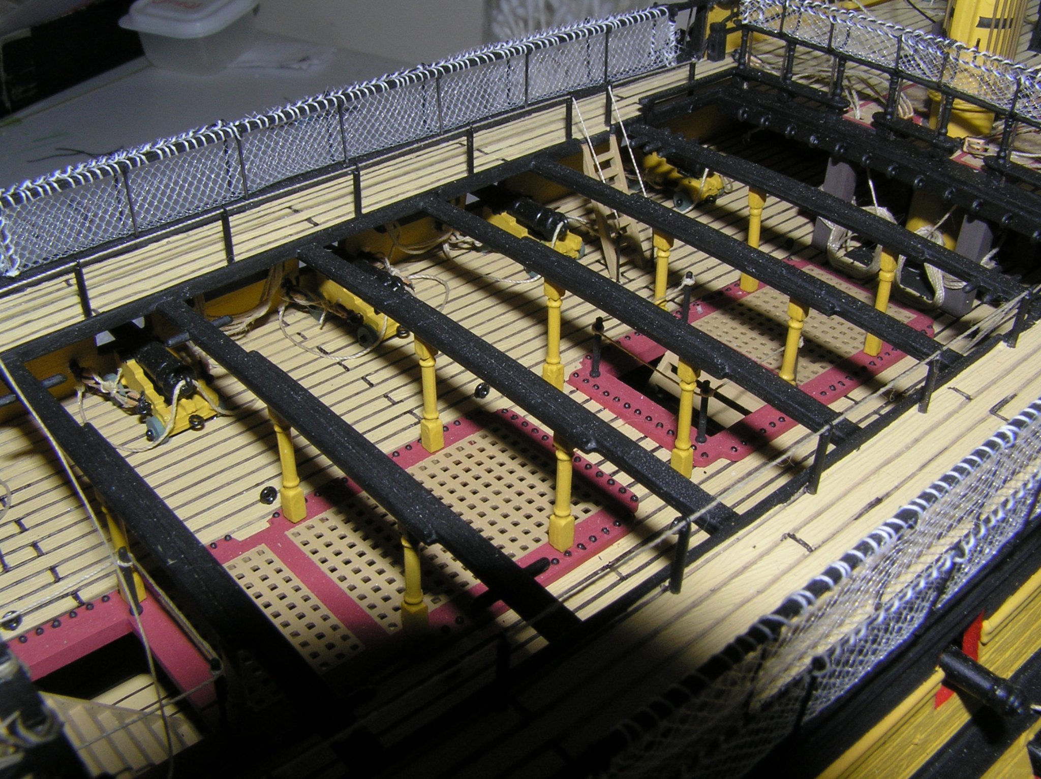
O.C. has it nearly right. Daniel wants you to increase the width of the top wale (runs along the hull below the main deck gun ports), by adding a single 1mmx0.4mm strip along its top edge, and three of the same strips along the bottom edge. He is saying that the wale as molded is narrower than the length of the preventer plates thus they cannot lay flat on the hull. I didn't do that; of course not all his instructions were written and translated back then. I don't recall having any problems, in my ignorance. Marc is correct; the evergreen on the bulwarks is a different "experiment" Daniel has made on this practice hull. The bulwarks were low at Trafalgar, shockingly so when you imagine shot passing over the deck with the foredeck guns crews closed up! I've seen shots of Victory sitting at Portsmouth with closed in bulwarks but that was in Victorian times, after her seagoing career. Here are the fore chains on my model, attached to the as-molded wale; Bill you can decide if you can get away with it:

-
Yes they have been inspired, and Carey is playing at his top level. Fun to watch!.....(later edit).....except for the perennial NHL playoff terrible refereeing!!!!!!!!!!!!!! Lord no, as far as I know no one can go into a rink yet. Usually I go lunchtime skating in the fall but this year I had to wait until the canal was open to go skating and unfortunately this was a very short season for the outdoor ice. The minor hockey leagues didn't run as far as I know, though at one stage they were having intra-team scrimmages. I'm glad my kids got to experience minor hockey play until university, before the world came crashing down.
-
So is this happening under a license from trumpeter to use their plastic?
- 225 replies
-
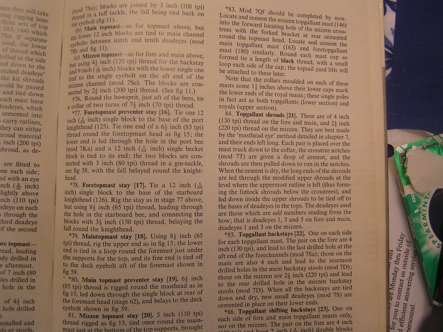
- 4
-
-
- I Love Kit
- Hood
- (and 2 more)
-
Hi Bill; CA means "Cyano Acrylate" glue. Yes, it gives you a few seconds before grabbing. There is regular and gel. Regular is great to lock a knot in rigging thread as it is so watery it gets absorbed; on the other hand even a tiny drop can seep along the thread and be noticeable due to darkening. Gel is better at staying put. There are people who will tell you that CA in rigging will crack up. Maybe they're right and a drop of shellac is best. I don't know.... And by the way: GO HABS GO!!!!!!!!!!!!!!! GO HABS GO!!!!!!!!!!!!!!!!!!!!!!! GO HABS GO!!!!!!!!!!!!!!!!!! Ole...ole....Ole.....Ole.....!!!!!!

-
Bill, I use gel CA like this: https://www.homedepot.ca/product/krazy-glue-krazy-glue-gel-2ml/1000421795 Great news about your new parts! Look forward to seeing you progress.😃
-
Oh no, nothing negative. "Kit bashing" is slang for making modifications with non-kit materials to enhance the final product. Could be as little as using different cannons, or as much as Marc's extreme bash on the "Soleil Royale" 🙂 Marc hope the term "bash" alluding to your SR does not offend you!!!!!! It is an inadequate word to describe the incredible work you have done in widening the hull, adding all the frieze details, and completely rebuilding the stern!