Modeler12
-
Posts
1,716 -
Joined
-
Last visited
Content Type
Profiles
Forums
Gallery
Events
Everything posted by Modeler12
-

Red Right Returning, history question
Modeler12 replied to Modeler12's topic in Nautical/Naval History
Here is another example how mixing the British and metric system can lead to problems. I used to work for one of the US national laboratories and as engineers we would turn our sketches over to a drafts person. Most us would have the dimensions in inches, but the drafts persons were under strict orders from DOE that drawings should be in metrics. So these drawings (after approval) would go to our shops where the machines, of course, are set to work in inches. The machinist would take the drawings and convert the mm into inches. . . etc. The problem of course was that the inspector would have to go back and forth, but I for one, was more concerned about the tolerances for those parts and with the constant conversions they sometimes ended up being different than what I had asked for. -
Red Right Returning, history question
Modeler12 replied to Modeler12's topic in Nautical/Naval History
Wayne that was excellent. Just the kind of information I was interested in. So this goes back as far as 1844 or so. -
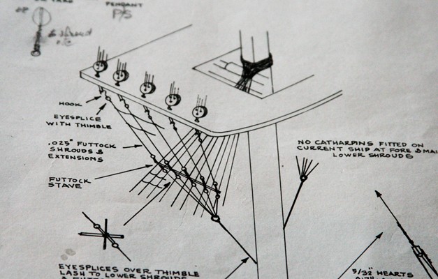
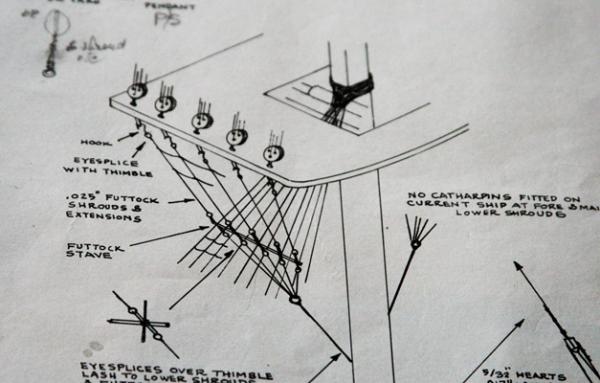
Hi Alstair, thanks for your suggestion about Morope. I never thought about it (despite the fact that you were using it already back in 'the good old days'). I brought up the web site but could not find any prices. Do have to send them an email to find out? I have a rope walk and made some of my own rope but all of it is cotton. Someday I will have to try some other materials like your Morope. Rigging the Conny is challenging but I find it interesting and am learning a lot about the terminology and what each line is for. No redundancies here. Of course it helps to have some reference books and the drawings that came with the kit are excellent. They not only give you the basic plans but add a lot of schematics to explain details. See below for an example. Of course an architect would cringe at the printing. At this point I have rigged the mizzen as far as I want to go. At the very top are three haliards that come down after the bottom shrouds are in place. But that will have to wait. The same applies to the ratlines. I also still want to replace those ugly square blocks with better ones from Floyd. I am waiting to see how many I need and any further surprises with the bowsprit and davids for the boats.
-
Red Right Returning, history question
Modeler12 replied to Modeler12's topic in Nautical/Naval History
Is this a bit like inches and millimeters, Andy? The US, and a few neighbors, still use that 'antiquated' system that was invented by the British. Again politics is one reason, but what is more important are all the machines and nuts and bolts that would cost a fortune to change. In my opinion, whether or not it was British to start with had very little to do with it. Period. I have a feeling the same applied to buoys at the time these two systems were decided upon. But I am still interested in the history and not the politics. -
Red Right Returning, history question
Modeler12 replied to Modeler12's topic in Nautical/Naval History
What about all of the South American countries, Andy? Plus all of this must have happened before the US became a world leader. I am sure politics had a role in making that decision, but I still find it strange that we have this weird division. -
Red Right Returning, history question
Modeler12 replied to Modeler12's topic in Nautical/Naval History
You are right when aboard a boat or ship, but I was referring to are the buoy colors, not what ships have to use themselves. Sorry, but I don't want to confuse the question. This is what I was referring to: 'For historical reasons, there are two regions of lateral marks in use: IALA Region B in the Americas, the Philippines, South Korea and Japan IALA Region A everywhere else. The two regions differ principally in the colours used to denote the two sides of a channel. When approaching a harbour from seaward, Region A places conical green marks to starboard and cylindrical red ones to port. In Region B these are replaced with conical red marks to starboard and cylindrical green ones to port.' So what is so special about the Americas being different??? I remember entering a port in Austalia and proudly pointed out the markers to my wife and mentioned that 'Red Right Returning'. We should have run aground because our ship did just the opposite. -
When ships come from sea and enter a harbor (or channel) the buoys are red to the right (starboard). That is true in the Americas, Japan and Korea. But the rest of the world has the opposite system. Why??? I was told ones that it was to fool the British during the War of Independence when their ships tried to enter the coastal waters of the revolutionaries. I rather doubt that interesting story because I don't think colored buoys were used back then. Does anyone know the history???
-
Conversion charts. Inches to mm and visa versa. Use 25.4
-
The starboard side worked out a bit better. But still not perfect. I like to think that part of the problem is that the holes in the tiny deadeyes don't all line up the way they should be. I hope the larger ones on the main and foremast will come out OK.
-
Interesting photo, Crackers. I know that is not your name but I found the picture of enough interest to ask; "Where, what and so on??" Just like Jeff mentioned above, I also saw cannon balls on racks on deck. Perhaps not what the USN wanted, but it sure draws attention by the people seeing them next to the cannons. I am sure they were only on deck during a battle and not while the ship was in heavy seas. So there is room for both???
-
Display Stand
Modeler12 replied to PageT's topic in Building, Framing, Planking and plating a ships hull and deck
I for one would like to follow up on this. I am also interested in a display case, but with different dimensions. Is there, or was there, a thread along those lines before, or can you help Page T and me start this one?? I can make one but need suggestions about how to join the corners, etc. BTW Welcome back to modeling. After thirty years you are probably a bit 'rusty' .,. like me and my poor hands . . . -
Ship Modeler's Workbench
Modeler12 replied to CaptCraig's topic in Modeling tools and Workshop Equipment
I am sure that before you started this construction you must have had a pretty good idea of what you had in mind. Since you explained (sorry for my earlier post), I must admit that I envy the fact that you can do this. I for one, I am doing things in a garage with (luckily) two cars and find it works for me. It all depends on the tools at hand and how to arrange them. I have to work along walls!!! I have a bandsaw, sander and scrollsaw all hookup to a vacuum cleaner and can use them as needed. My old trusty Shopsmith is to the right. The 'real' workbench it behind me as I take this picture. How often do I use all of this?? Not often, and when I go into 'major' I move one or both cars out.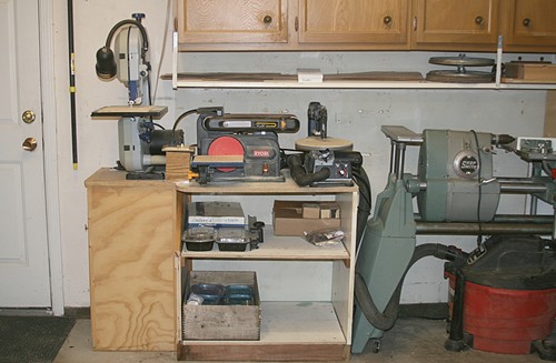
-
"I know the problem. Us old guys with big hands and small deadeyes and even smaller threads really make things hard." I like that Geoff and you are right on. My deadeyes are much better now that I have a decent magnifier (it took your dog's picture to convince me). But now I see things that are much worse than before But I still have those big hands. As I go along I find more and more things that I can or could have done better. Some I can fix, some 'maybe'. Hopefully they are the little ones. But I won't stop too long to fix. I want to progress, go further and see. I did add some epoxy to the deadeyes on the mast-tops. I know that helps, even though I had to re-drill a couple plugged holes.
-
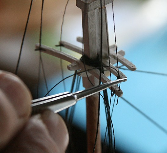
One of the reasons I decided to go dark, Geoff, is that all the pictures I have seen of the Conny in harbor showed a lot of 'black'. I decided a long time ago that I wanted to have my model show 'wear and tear', which makes it a lot easier to add booh-boos, even if you don't meant to. But I am finding out that there are a lot of details that cannot be hidden. For example, the picture below of my 'bad side' (port in this case) is my latest attempt to do the deadeye rigging of the mizzen top. The lines are a bit tighter (I repaired), but the way the ends are tied together stinks. (well, reeks). I guess the magnification has something to do with that and if you say that is ok, I will go with that. After all, when I stand back it looks pretty good. Perhaps I should not take closeups any more.
-
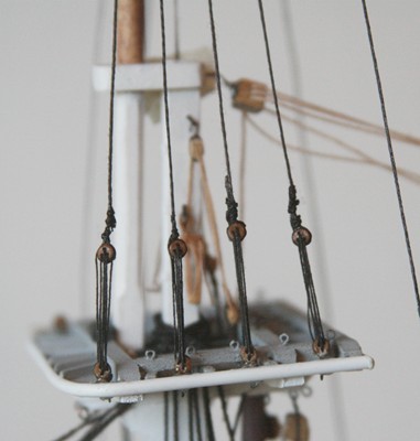
Geoff, all it takes is lots of patience and a steady hand. I wished I had some of that. Here is the first try to rig those mizzen-topmast deadeyes. I don't like this one because it is too loose. I am still a bit shaky about pulling too hard on those little guys. But practice should help. I probably will do this one over again. I know some folks like to use tan lines, but I thought this is part of the standing rigging, so I am going with 'tar'.
-
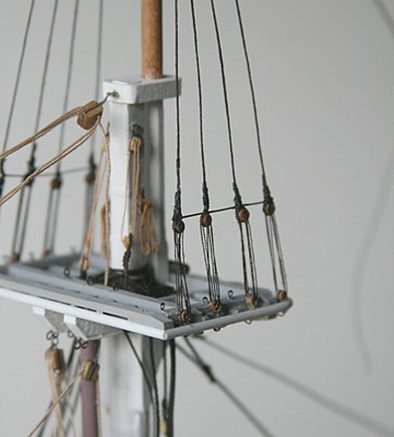
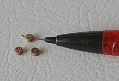
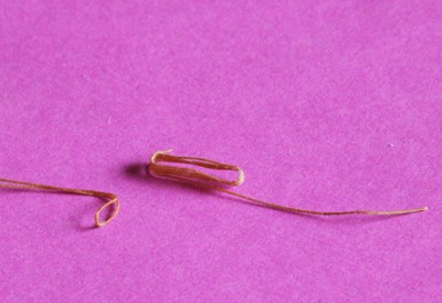
The topmast shrouds came next. Here is what it looked like for the mizzen shrouds. Again I made a simple fixture to hold the tiny deadeyes so the spacing between them was 3/4 inch. I also show how small these guys are. The pencil lead is 0.5 mm in diameter.
-
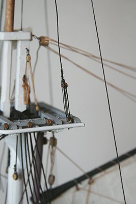
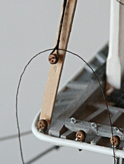
I showed the picture below on another thread where someone talked about using a threading tool. I have used that wire gismo but now use a drop of CA glue at the end of the line I want to thread. I smear it for about half in inch, keeping the line flat and let it dry. Then I cut the end at an angle to get a bit of a point. I have used this on tiny blocks and on the small holes for the topgallant shrouds that have to go through the 'spreaders' or crosstrees.
-
En hartelijk bedankt voor die mooie woordjes, Carl. Your Seawitch is coming along nicely. That is one small, complicated boat you are building, my friend. Do you happen to own the real one? Nice picture of it sailing along in one of your canals??? I had another look at the picture and realized she is flying the US flag and the banks of the canal are not green enough to be in Holland.
-
Well Carl, join the crowd. This is my first major project and I am learning as I go along. The reason I started at the stern is that the mizzen mast on this model ship also has a second mast right behind the main one. It is the spanker mast and is attached to the principal mast at the top. Since I had decided to add some sails, I had to put all those wooden loops on the spanker mast before gluing the two masts in place. They have to go together. One thing led to another and I wanted to see how the first sail would look on the model. Hence I started with the spanker sail and things fell in place from that point on. There are a couple other things that are important. The shrouds for all three masts have to go around the top before the second part of the mast goes in place. The same applies when you add the third part of the masts. Hence the shrouds for the top masts is where I am now. I know that some modelers start at the bow and work backwards. I just happen to do it the other way. I really don't know what the advantage is one over the other.
-
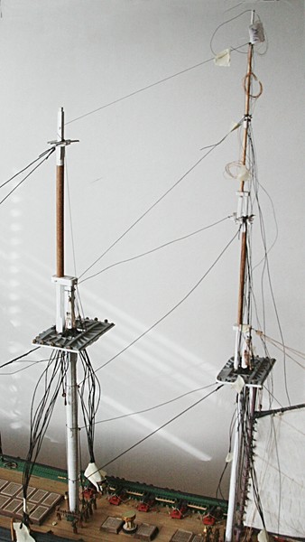
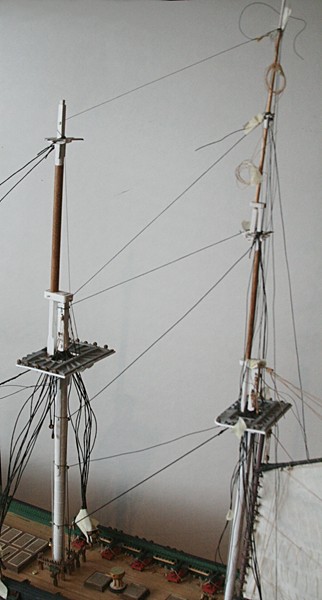
I had to take a look at the last picture of the rigging above. It looks nice and tight, right? It was, but no longer. I added the shrouds for the mizzen topgallant. Then I put the topmast in place and had fun rigging all those lines that were attached previously. It all came together alright; they fit in the right places, but they did not quite tension the same!! Compare the two pictures below and notice how the earlier stays are now a bit slack! It is not major but the tilt of the main and mizzen masts are different. I think the actual angle is not as important as 'how it looks'. Luckily I did not glue all of them in place (except one). I used a lot of pieces of scotch tape to modify the tilting of the mizzen masts until they looked about right. I am still waiting for more of those 'gotchas' so I am not glueing yet. Note: I don't worry too much about the alignment of the masts sideways. They look fine in that direction and the shrouds are probably just an 'add-on'. Will that be another 'gotachat' in the making???? But when you look at the ship sideways, whooow!!!! A few adjustments of all the lines should help. Oh, pieces of masking tape are invaluable.
-
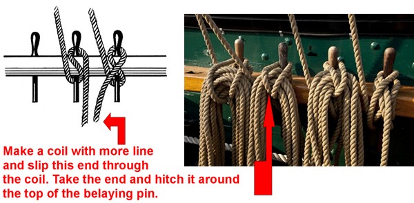
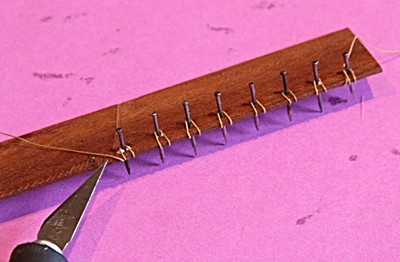
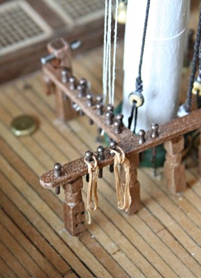
There are a couple more ways to do the coil around a belaying pin. One is to use the line that you have hitched around the pin. You make another flat coil with some more line and hang the coil around the hitched line. The picture below should tell you the story. What I like to do is to make the coils ahead of time and store them until I need them. I use several different sizes. Below is one variation of what I showed earlier. It ends up looking a bit more like the photographs. I make a series of small loops on a board with brats and hook those through the coil. This shows a couple just looped around a pin. Keep in mind that the sailors had to be able to grab the line and know exactly how it is looped around the pin. They would have to do this blindly in the dark and heavy seas. Hence all lines were belayed the same way.
-
Keep it up Jim. You are doing a great job. Love those details. When you look at the deck from astern you can really see that you paid a lot of attention to the planking. And now you are doing the same with the wheel and housing. You know when we work on those details it is nice to step back and say, 'Damn, that looks good'.
-
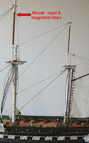
OK Carl, this must be an old Dutch proverb. I never heard that one before, but it should be easy for you to tie a rope to this (but make a tiny rope, please). As you can see below the rat-nest has been cleaned up. The lower shrouds are tied in little bundles and sort of out of the way. That gave me room to add the main and mizzen topmast stays (including the 'preventer' stays). The royal and topgallant stays are taped to the top for the time being.

-
Amen to that Geoff. As you know, I am taking a totally different approach by skipping over details that I will come back to later. I have not done the bow carving, boats and netting among others. But I am aware of how far I can go with other things and the rigging is one. For example, I am putting the deadeyes on the shrouds but will not do the lanyards to tie them to the channel deadeyes until much later when most of the rigging is done and in place on the various belaying pins in the center of the ship. I keep thinking about making the bowsprit, but then I find that having to turn the ship around a lot to get to the shrouds and stays, it is easier if the bowsprit is not there. By the same token I cannot attach the forestays on the foremast until the bow is in. etc. etc. However, I really think that starting the rigging at the stern and working forward and up is better than starting at the bow. Or maybe both can work equally well. I don't know. I am too far along to even think about trying it.
- 732 replies
-
- 1
-

-
- constitution
- model shipways
- (and 1 more)
-
You are absolutely right, Alistair. When I mentioned not having fun, I was only kidding because of what looked like a confusing mess of shrouds. But actually it is exciting to see things come together and make it look like a sailing vessel. I have had my share of 'oops' with the deadeyes that are mounted on the channels. There are a total of 56 of them in two different sizes. Some of them were a bit loose and needed a bit of 'encouragement' with some epoxy, and then there were some that I had mixed up the sizes. Between having to wait for the epoxy to cure and then come back to an oddball, it is taking me a while. But I am getting there. Once the lower shrouds have their deadeyes I will start moving upwards again with the upper masts and their shrouds and stays.