HOLIDAY DONATION DRIVE - SUPPORT MSW - DO YOUR PART TO KEEP THIS GREAT FORUM GOING! (Only 24 donations so far out of 49,000 members - C'mon guys!)
×


Bender
-
Posts
213 -
Joined
-
Last visited
Content Type
Profiles
Forums
Gallery
Events
Everything posted by Bender
-
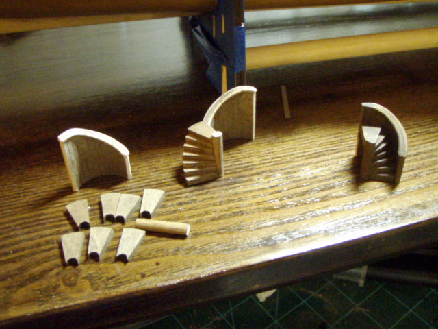
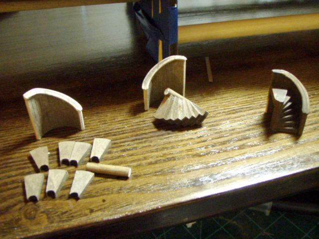
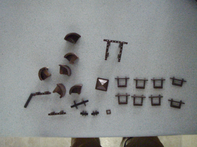
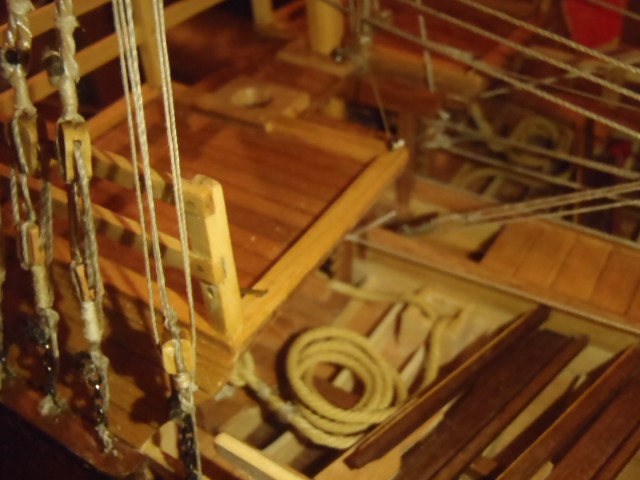
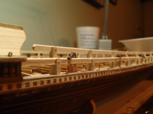
 Originally posted June 22, 2009. The kit supplied 48 laser cut plywood steps. There was nothing to do but sand these pieces. These step pieces were then glued to a piece of dowel, forming a spiral. The curved rails were then glued to the spiral steps. It took a lot of sanding and staining to cover up the ply layers in the plywood steps. Total time for the six stair cases was nearly 50 hours: over 8 hours per step unit. Step pieces. Steps glued to the dowel, forming a spiral. Winding stair case ready to be installed. Bunch of deck stuff ready to be glued The next 3 pictures show the stair cases in place.
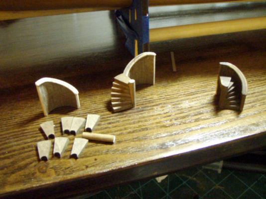


-
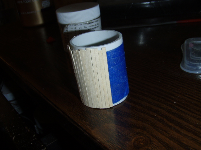
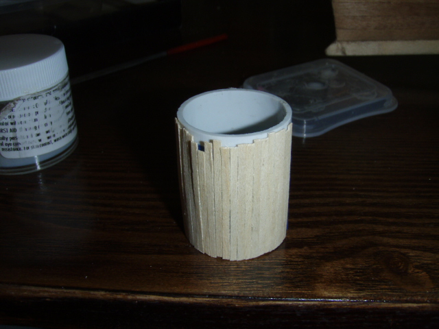
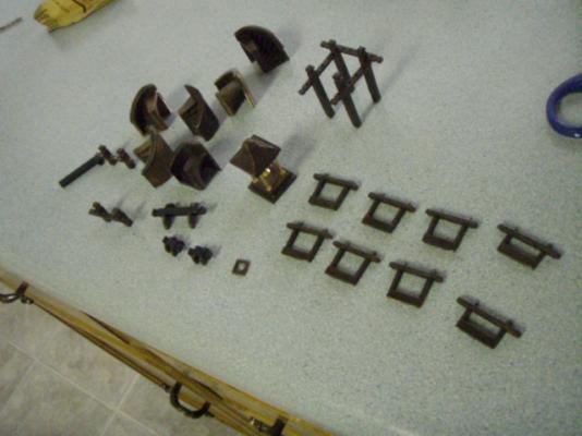
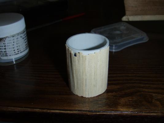
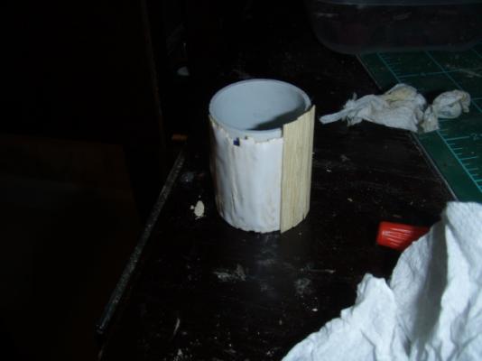
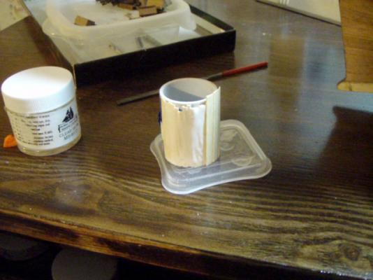
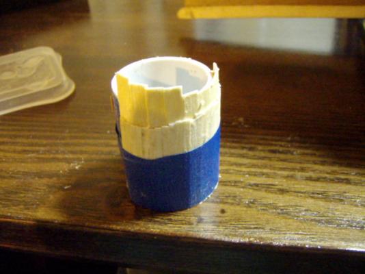
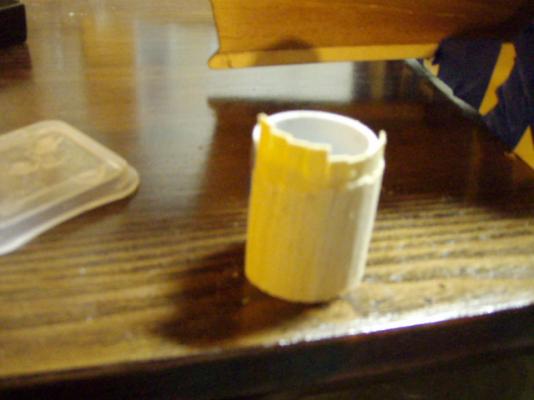
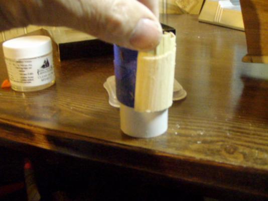
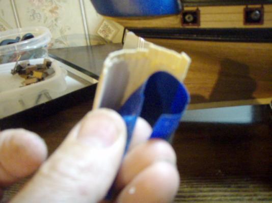
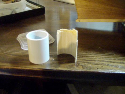
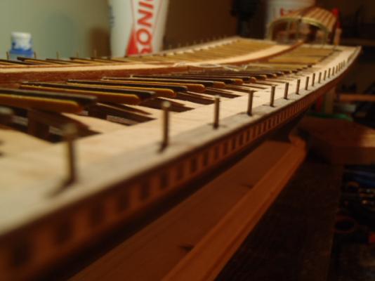
The following was orginally posted on June 22, 2009. I built the winding staircases this week. The ship has 6 winding staircases, and the kit supplied laser cut plywood pieces for four solid stair rails. The direction showed two of the staircases with open stair rails. I could not see why four staircases are solid and two open, so I scratch built two solid stair rails. I included pictures of the two scratch built stair rails. The kit supplied a plastic tube (32 mm diameter) to form the railings. For the 4 rails the kit supplied: first, you glued two pieces of laser cut and engraved pieces of plywood together back-to-back. Second, bend them around the tube and tape. Let the glue dry and you have one curved solid rail. Last, a top handrail was glued to the top edge of the curved rail. For the two rails I scratch built, I wrapped tape around the tube with the sticky side out. I then cut 26 pieces of 0.5 mm thick strips of planking and stuck them to the tape. Next I spread glue on these strips and stuck 27 more piece of 0.5 mm strips on the glue. I then tightly taped around the tube and wood strips, let it dry, slide the railing off the tube, remove the tape, and then sand and shape.


-
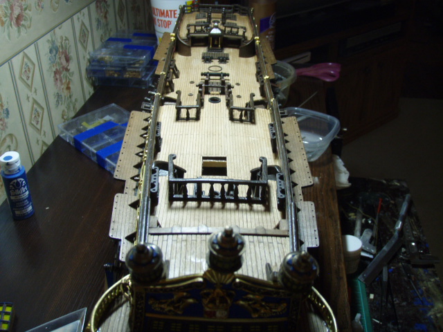
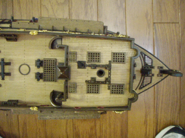
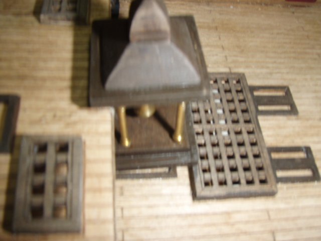
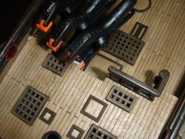
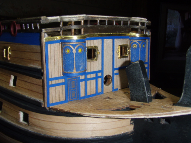
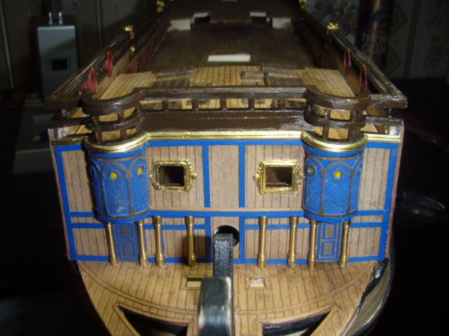
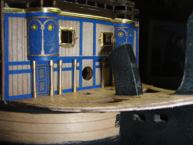
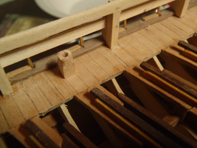
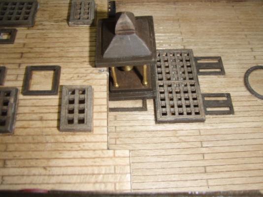
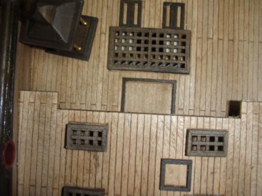
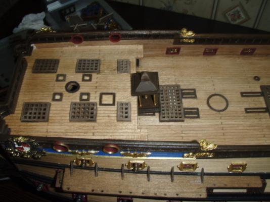
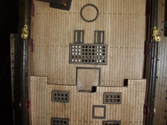
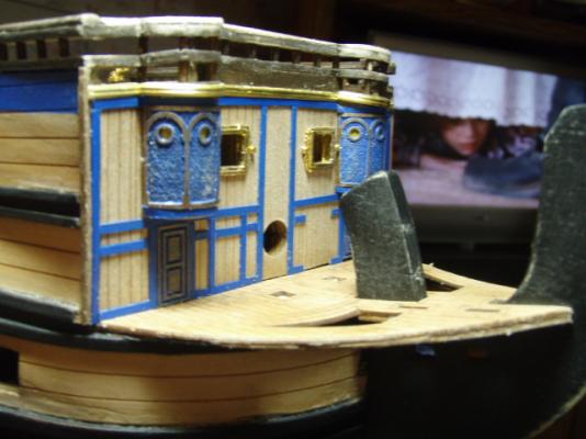
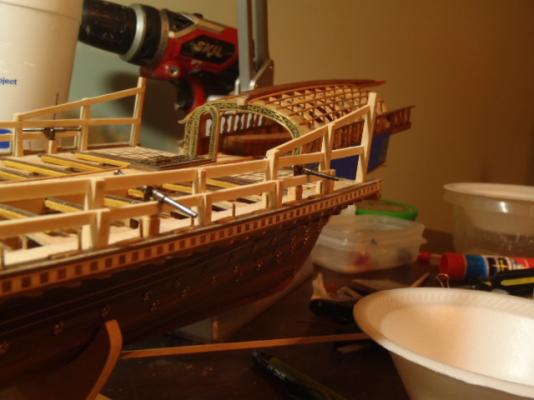
The following was originally posted June 19, 2009. When something does not line up, the first words out of my mouth is, “What did I do wrong?” As you can see from the first four photos, the bell and its little house do not fit into its position. The deck above is sitting too far over. It could not be the main deck out of position because notches in the false deck sit in the break-off tabs on the bulkheads. The deck above sits in a notch of the front bulk head. So, as I thought about it further, I realized that if I glued in a deck out of position then there would be more misalignments. Everything else lines up. The holes in the two decks for the foremast line up. The next question is, did I position everything on the main deck in the correct place? Position of everything on all the decks are dummy proof. The decks are laser engraved. There is a square engraved on the deck where the bell is to be position and a hole for the gratings right behind the bell. So my conclusion: ?????? Could Mantua have made a mistake like this during their revision of this kit? I ended up having to cut out a portion of the upper deck. When the bell is in place you can’t tell the upper deck has been altered. No harm, no foul. Now 5 years later I am still not sure if I made a mistake or if the kit had a problem. Looking at the finished model now you cannot tell anything is misaligned. If anyone is building this newer version of San Felipe, let me know if you have the same issues or not. I am curious. In the next two pictures you can see there is not enough room to slide the bell house up against the grating. This is where I had to cut the upper deck so the bell house would fit. The hole is actually centered. It looks like I was holding the camera a little off center. The bell house sitting in place.


-
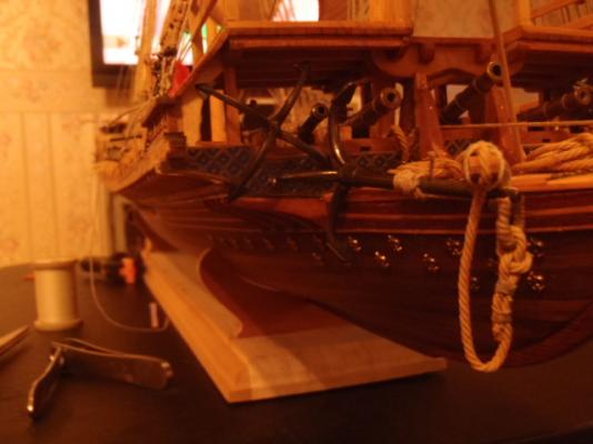
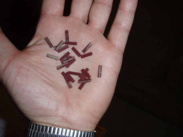
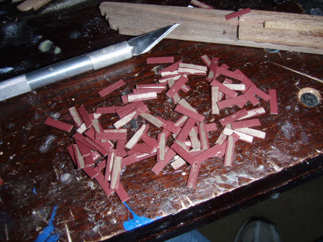
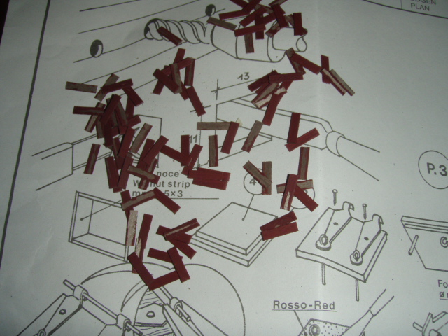
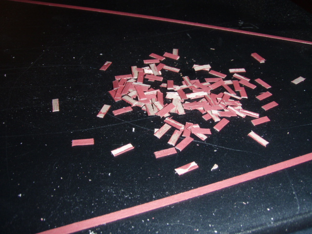
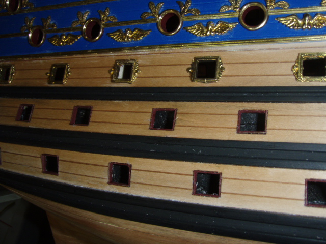
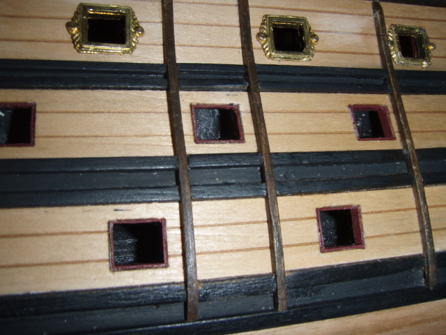
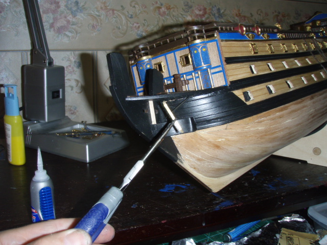
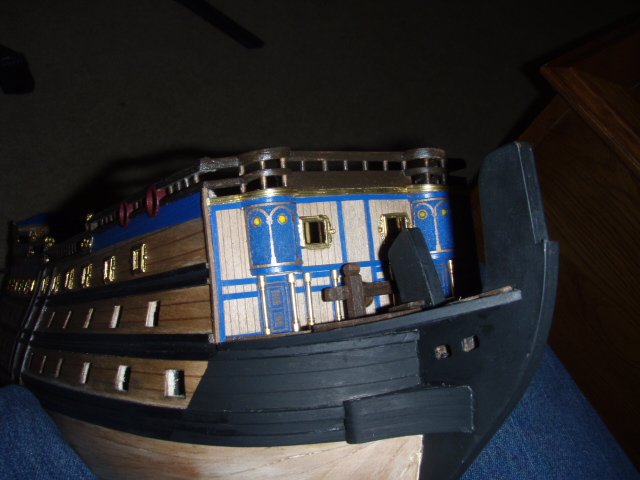
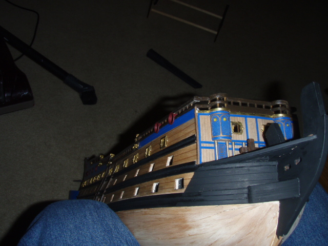
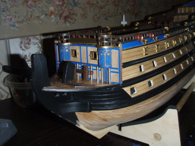
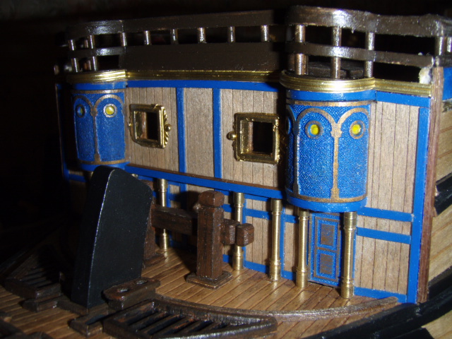
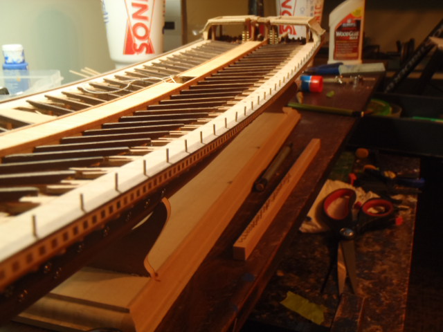
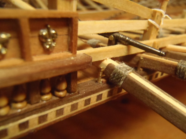
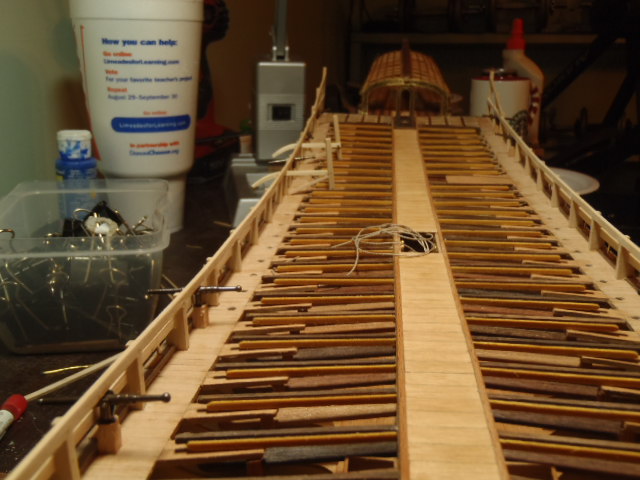
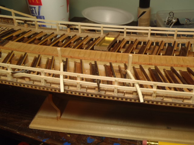
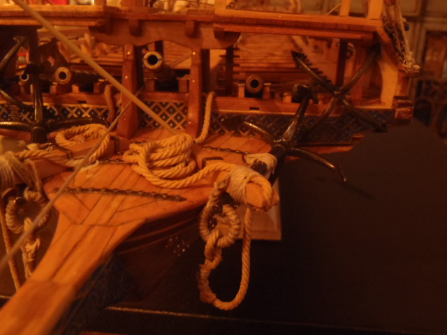
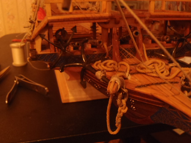
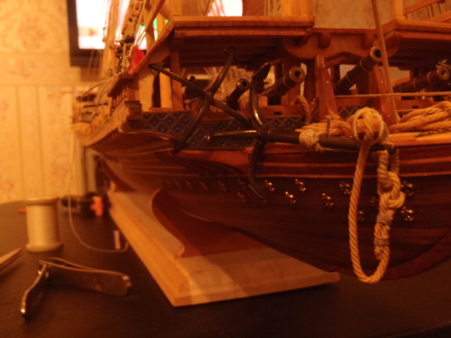
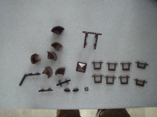
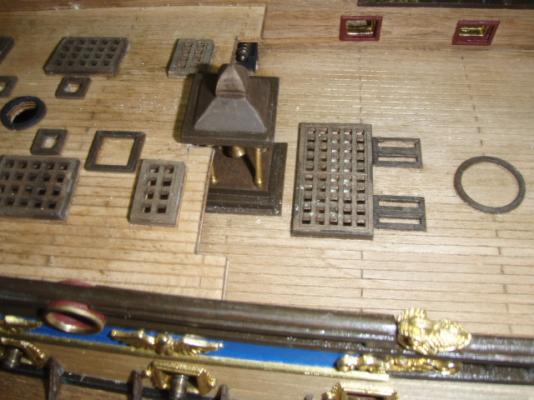
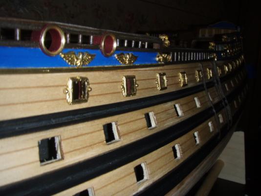
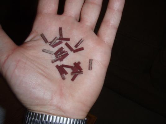
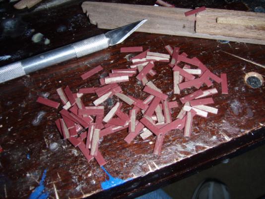
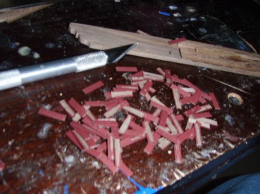
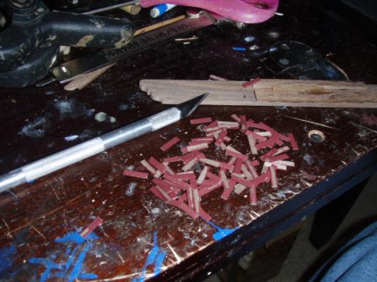
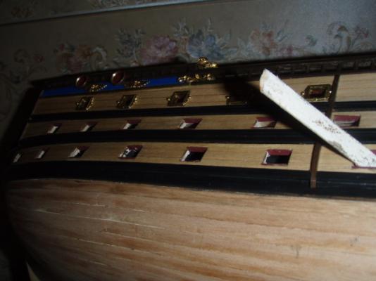
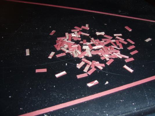
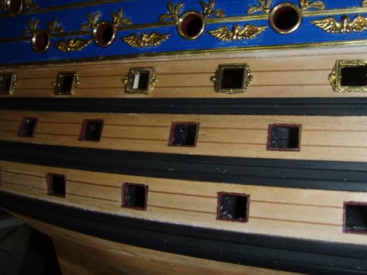
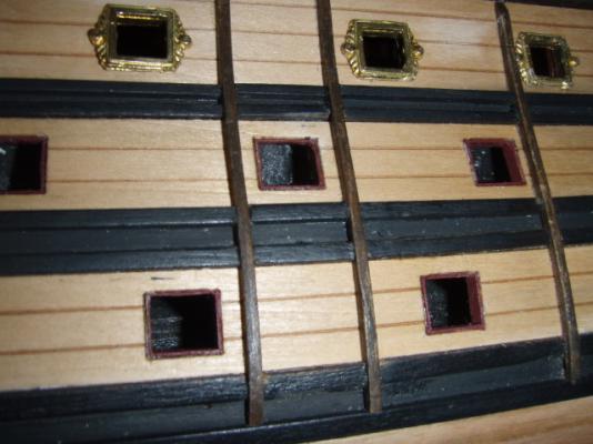
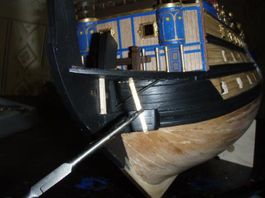
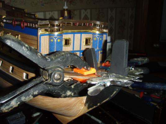
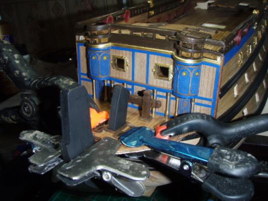
The following was originally posted May 29, 2009. I lined the cannon ports this week. The top sides, round ports were lined already. The main deck ports have brass inserts on the outside and frames on the inside. The lower two decks have 58 gun ports that I lined with .5x3 walnut. I painted the strips red before cutting to size. There are 4 more ports below the curve at the stern that I have not cut yet. I also glued on some of brass. Each piece of brass had to have bits clipped off and then filed to shape. There is still a lot of brass left to glue on.

-
I lost the pictures on the last two pages. Put them back in today.
-
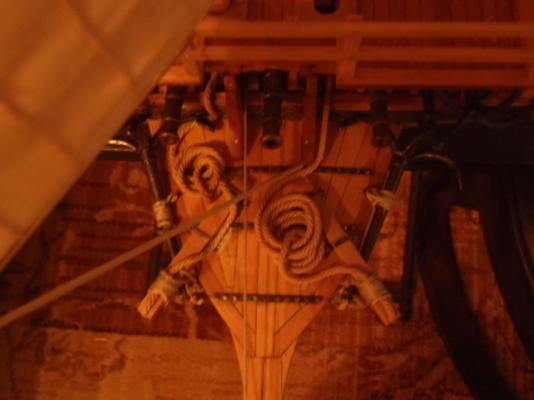
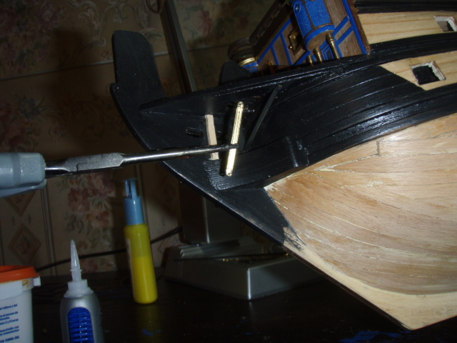
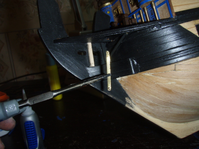
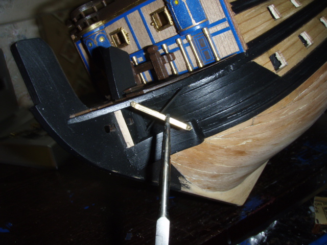
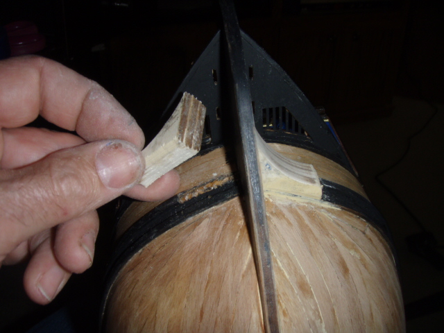
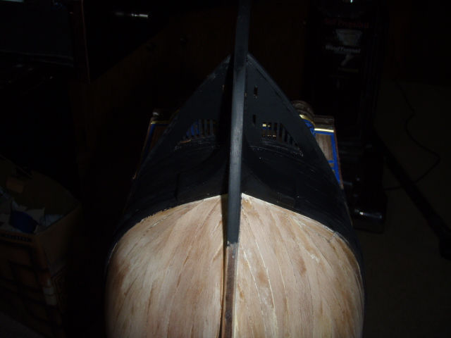
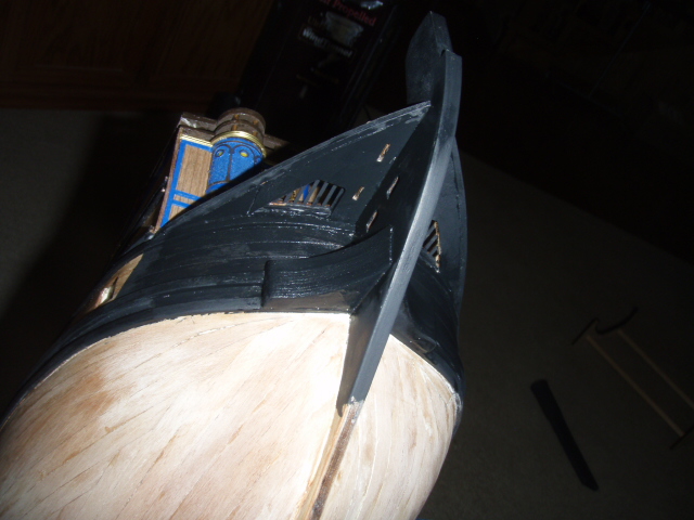
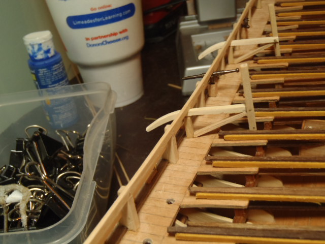
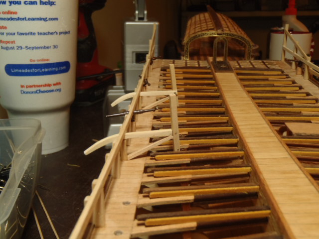
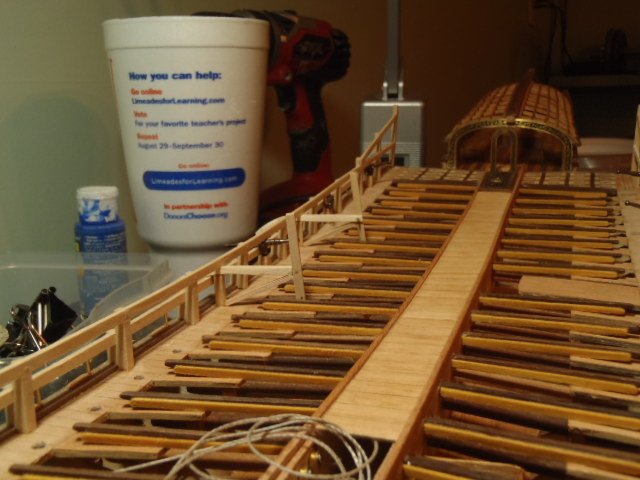
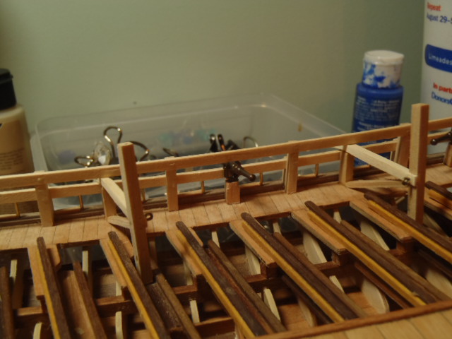
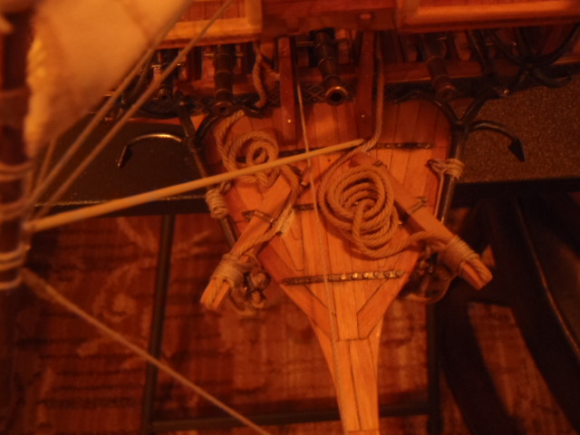
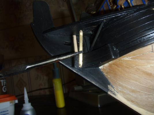
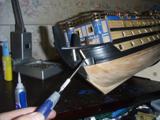
Here are the pictures of the braces under the beakhead deck.


-
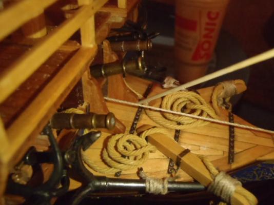
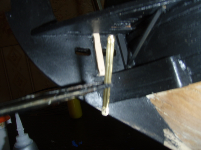
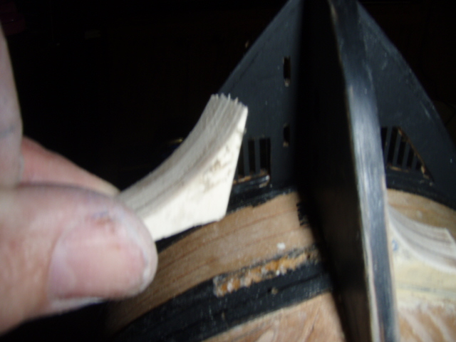
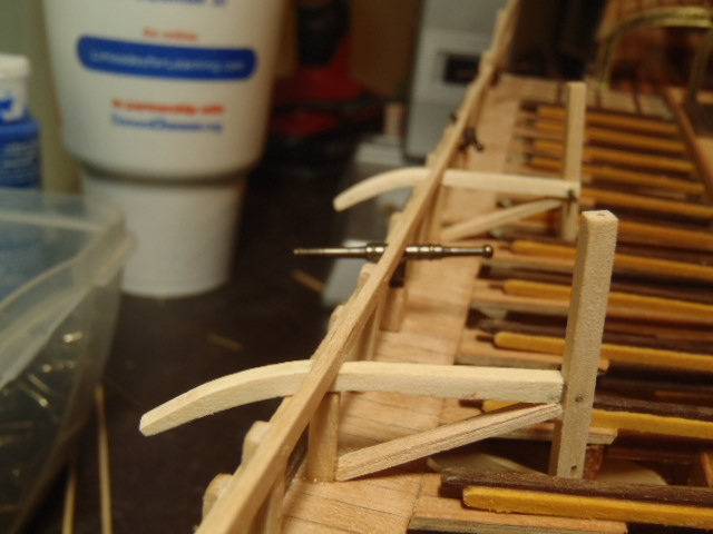
Hi, Salty Dog. The directions were not the best. See the post I made on the first page that shows where the sheets of plans differed from the direction book. The following was originally posted May 2009. I trimmed out the very front of the ship, the beakhead deck and round houses. The crew’s toilet was supposed to be a three-whole seat, but I couldn’t image sitting cheek to cheek with two other guys while taking care of business. No actually, after six tries of trying to drill three 3mm holes through a piece of 2x6x14 walnut, I gave up and went for a two-hole seat. I ask about the roundhouses and toilet in one of the question forum, and Dinosaursoupman made this commit: “In rough seas [The seats of ease] doubled as bidets.” What an image! I put two of the three pairs of braces under the beakhead deck and will add the third this week. I have also glued on more of the brass parts. This week I plan to start lining the gun ports or maybe work at the stern of the ship.. After reading the above I went out to to see if I could make the three 3mm holes using my drill press. No problems. The right tool does make a difference. Here are some of the pictures from this part of the building.


-
Hi Duff, Jeff, and Jay. I was happily surprised when Modeler12 (Jay) PMed me and mentioned this thread. I haven't posted anything in awhile and hope to get back to modeling by summer. And thanks Jay for taking the idea further. AL
-
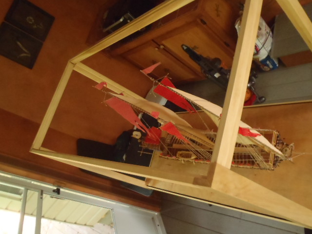
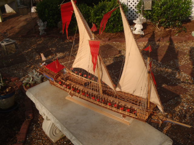
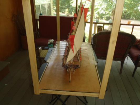
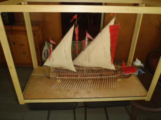
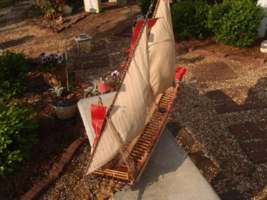
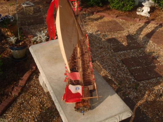
Thank you very much, Joachim. As the last pictures show, the ship is finished. I need to take some pictures of the ship in the case now that the case has the glass installed.
-
Oars installed.


-
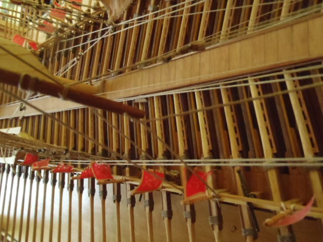
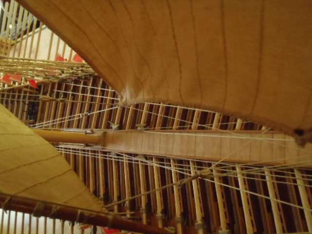
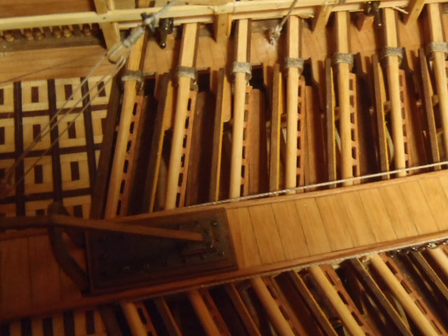
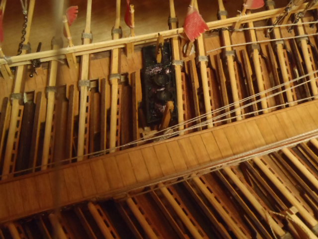
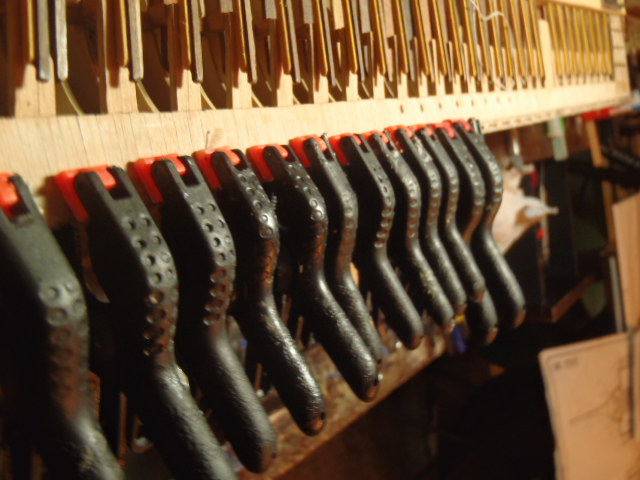
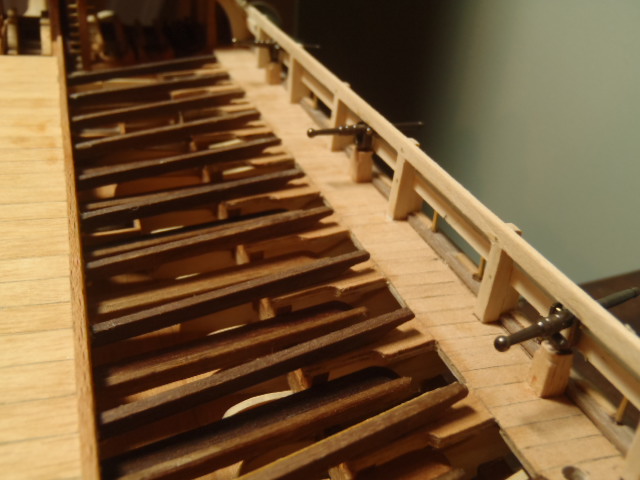
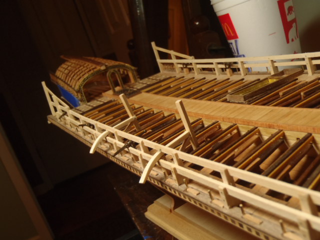
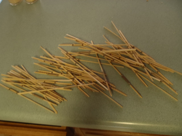
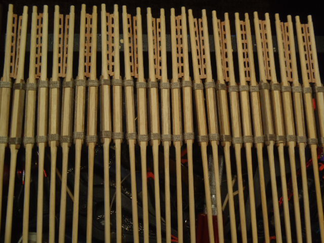
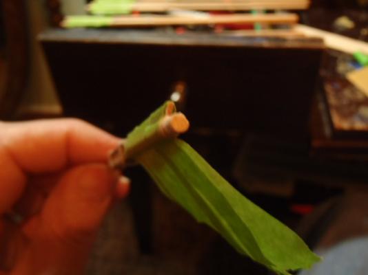
The oars: Each oar rests on top or a wear pad, and pivots against a "Thole-pin." To cut the 59 pins I cut brass rod a little longer than needed. I cut a piece of scrap wood to the thickness equal to the length I needed for the pins and drilled 59 holes. I inserted the brass pins into the holes so that a little stuck out on each side. I then used a belt sander to sand off the brass the protruded from the piece of wood. I ended up with 59 brass pins of equal length. Clamping the wear pads. All of this was dune before any of the rigging. Also before the rigging I attached the gun mounts. This caused an unforeseen problem. The wrap of string I used to tie the reforcement battens to the oars would not fit between the bottom rail of the hand rail and the wear pad. On some of the oars I could push the oar under the handrail ahead of the wear pad and then slide it backwards in place, but the vertical post for the hand rail was in the way for every-other oars. That was thirty oars that would not slide in place. The gun mounts were in the way of twelve more oars, so only 17 oars slipped into place. I ended up needing to remove the wrap of strip on 42 oars. I had used super glue on the knots, but the oars had already been coated with poly. After a bit of wiggling and prying the wrap of string came off and--because of the super glue--help its shaped. After I pushed the oar between the bottom rail of the handrail and the wear pad I was able to slide the wrap of string back into position.


-
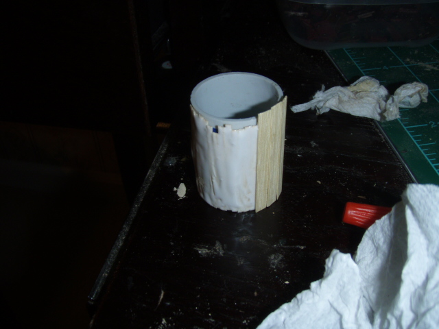
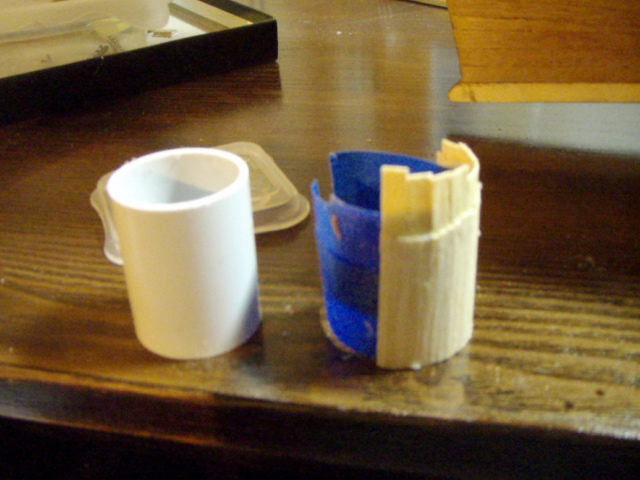
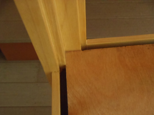
Is the piece made of plywood? And does the grain run left-to-right? If it's not wanting to bend, you might use that piece as a pattern and cut a new piece with the grain running up and down. Then once you have it attached you can then plank the piece.
-
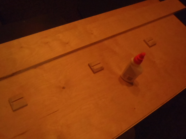
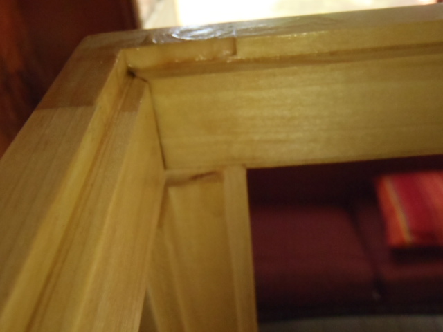
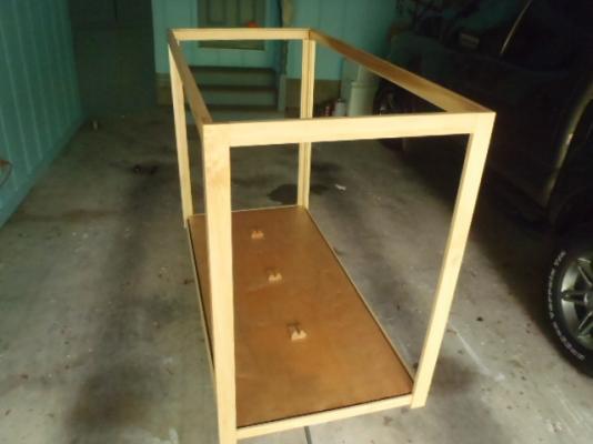
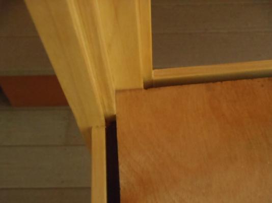
I used birch plywood for the base and poplar wood for the corners and top edges. This picture shows the clearance the oars tip has with the grove for the glass. I made three mount that fit the curve of the hull. Top edge and corner Bottom edge and corner Just for perspective. This is me.


- 115 replies
-
- 1
-

-
- reale de france
- corel
- (and 1 more)
-
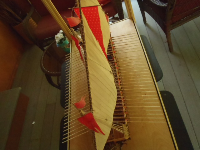
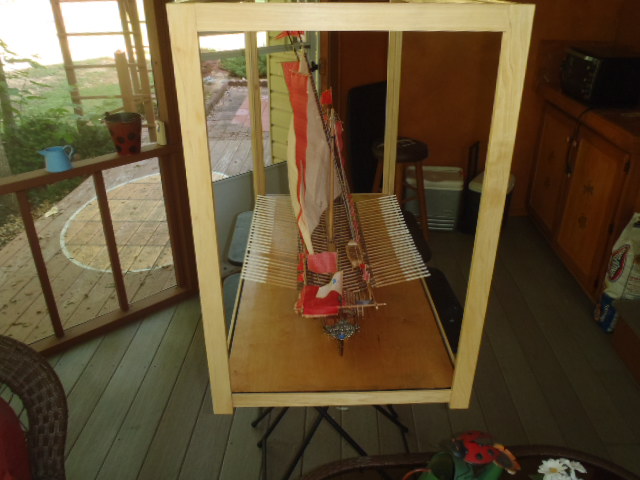
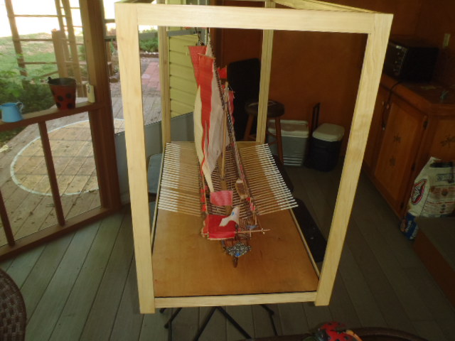
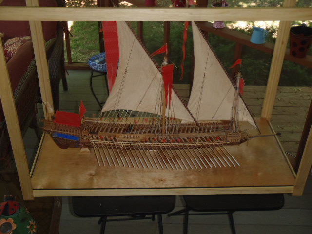
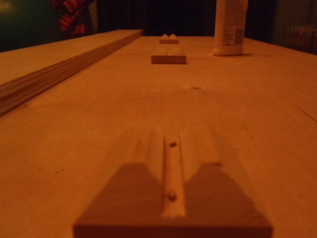
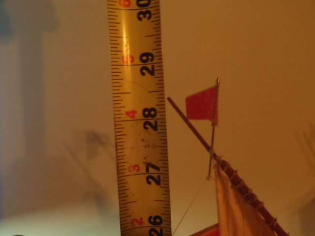
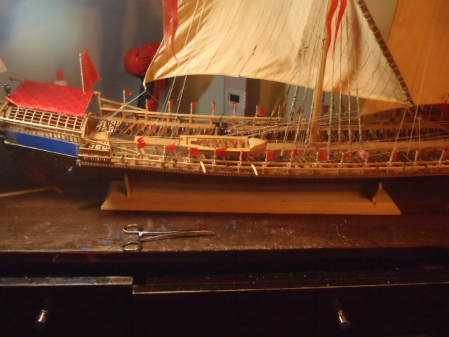
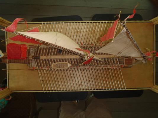
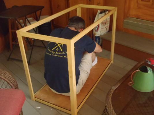
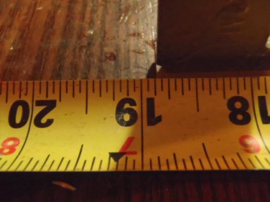
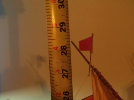
Before I attached the oars I needed to mount the ship to its permanent base, and because of all the oars sticking out I decided to build a case. The ship is rather large, and I didn't want the case to be any larger than needed. I attached two oars on each side and started measuring. 42.375 inches. (107.6 cm.) long. 18.875 inches. (47.94 cm.) from oar tip to oar tip. 28.75 inches. (75.57 cm.) to top of main yard and flag.


-
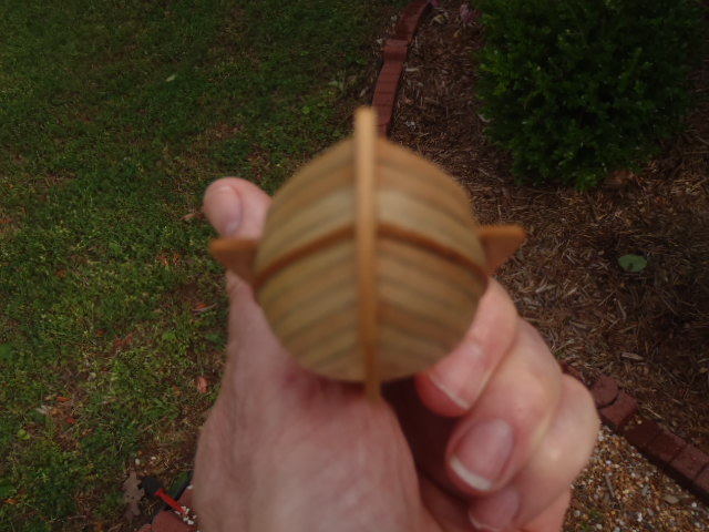
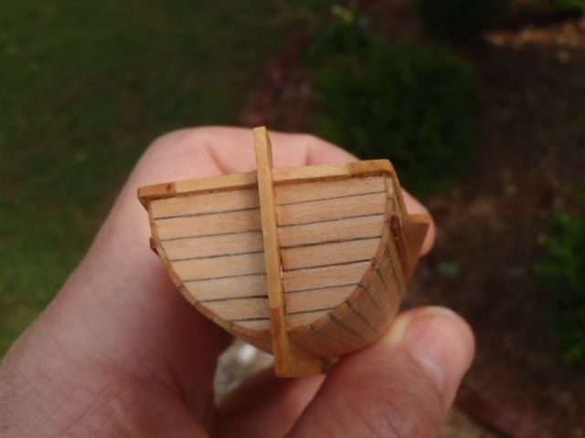
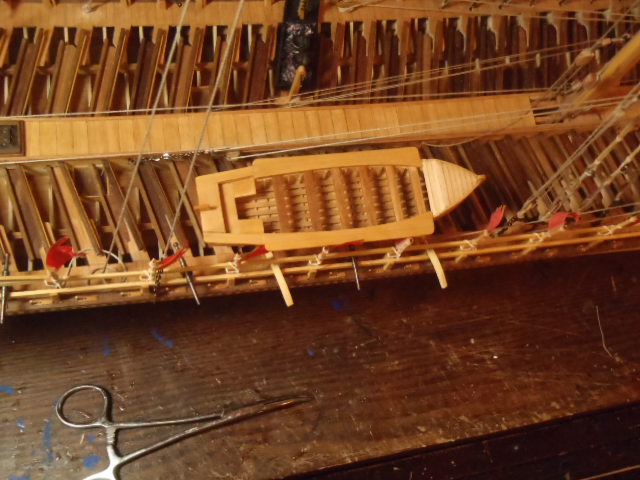
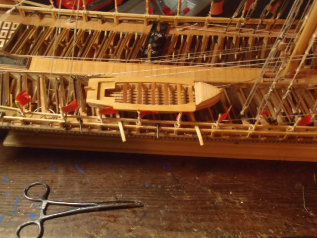
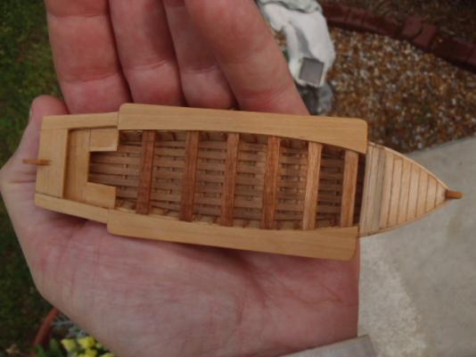
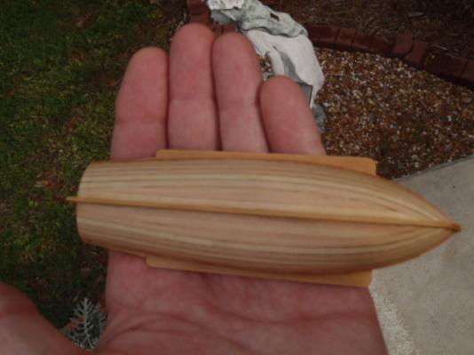
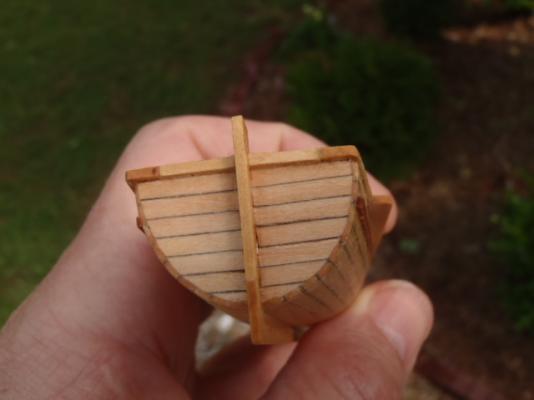
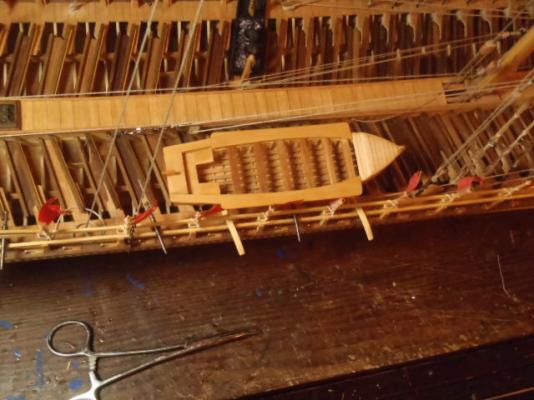
The boat kit that came with the Reale de France was one of the easiest ship's boat to build.


-
Thank you, Joachim and Hamilton for the kind words, and for the "wow," Hamilton.
-
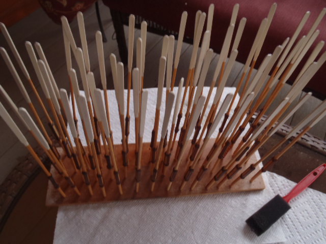
I painted the blades of the oars white. I coated the oars with satin poly and used a piece of scrap wood to hold all 59.


- 115 replies
-
- 1
-
-
- reale de france
- corel
- (and 1 more)
-
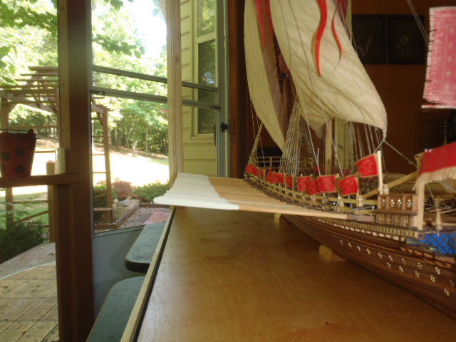
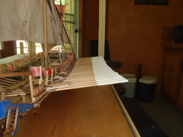
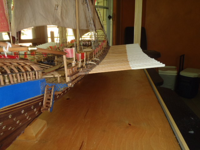
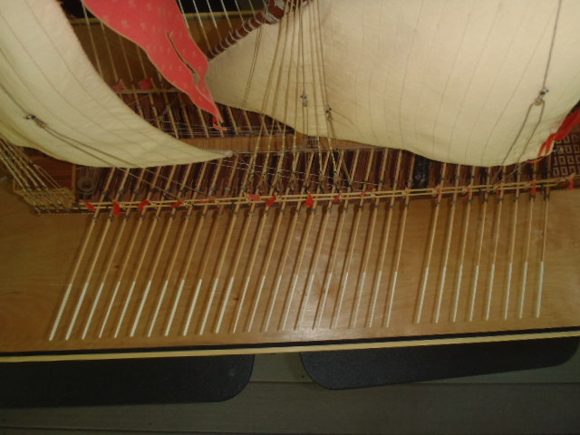
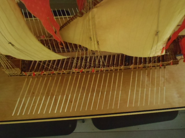
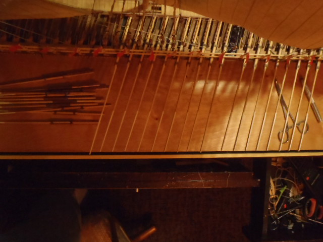
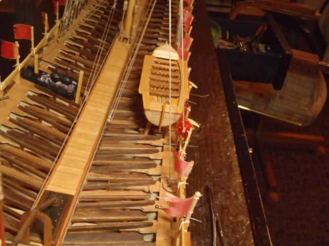
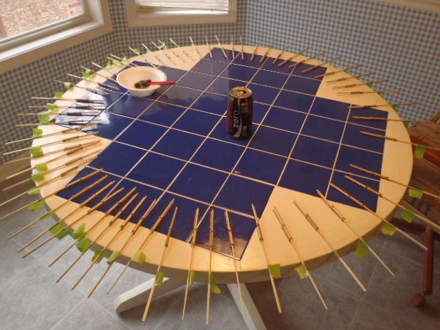
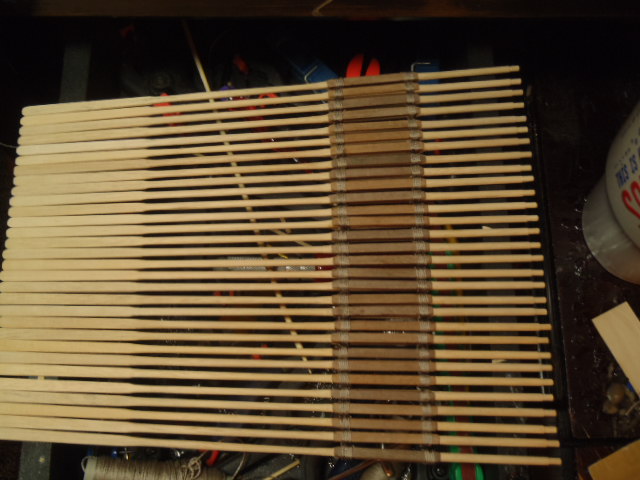
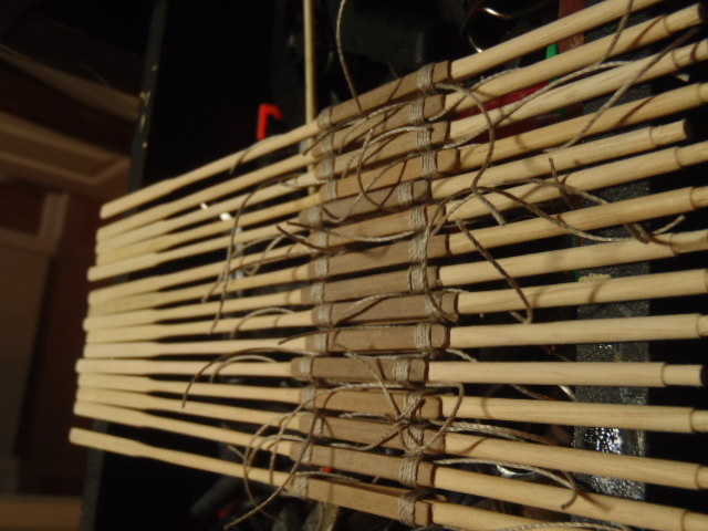
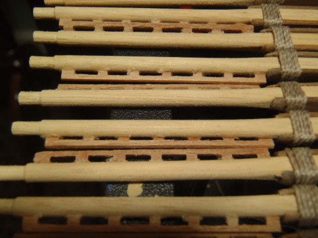
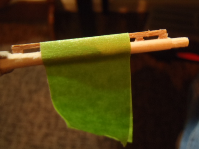
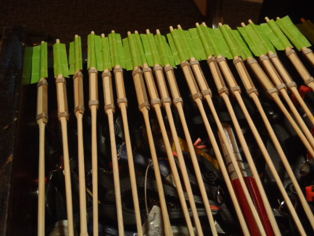
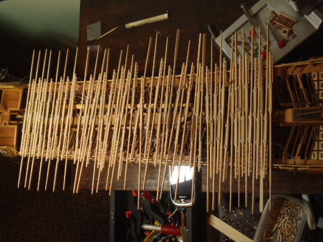
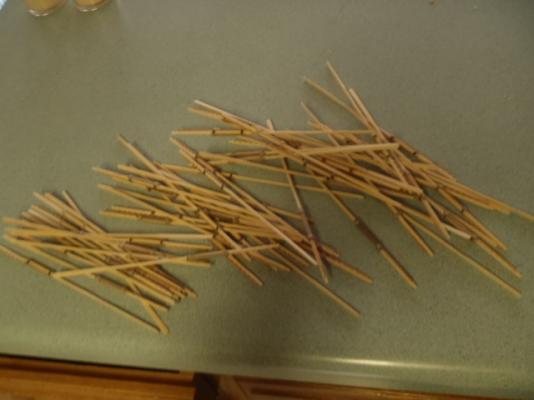
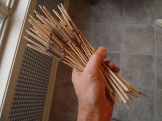
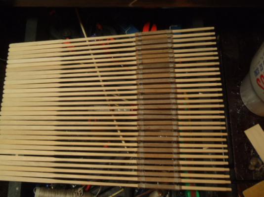
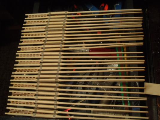
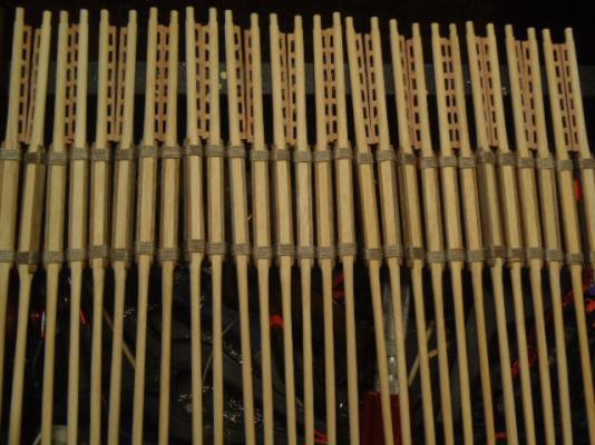
The oars came pre-shaped, only needing a little shaping to make each match and give some curve to the blades. I glued the Reinforcement battens to the oars where the oar presses against the oarlocks. The battens were lashed to the oars. Gluing the battens first made tying the lashing much easer. This is half of the oars. This ship has 59 oars. On the real Reale 6 or 7 men would pull on each oar. The oar itself was too big for the oarsmen to wrap their hand around, so handles were attached. I glued the supplied handles to the oars and held them in place with tape. Here are all the oars sitting across the side rails. Here are twenty-eight of the 59 oars. I made left and right oars. By doing this the lashing's knot is on the underside of the oar.


- 115 replies
-
- 1
-
-
- reale de france
- corel
- (and 1 more)
-
Thank you very much for looking in on this build log and for your kind words. I like hearing the historic information about the ship. Thank you for that too.
-
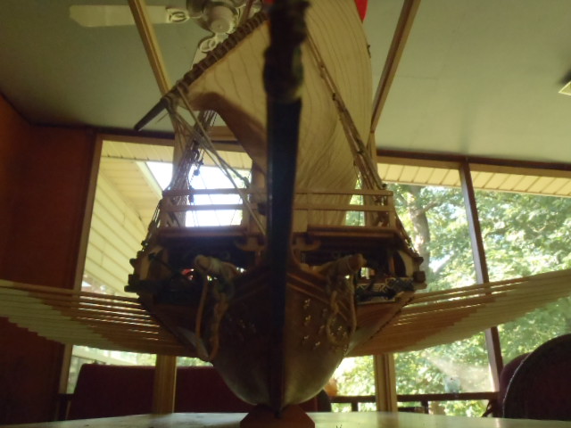
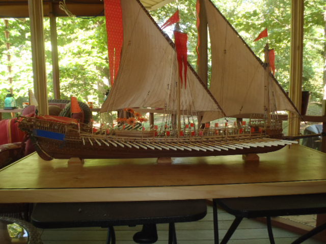
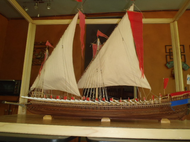
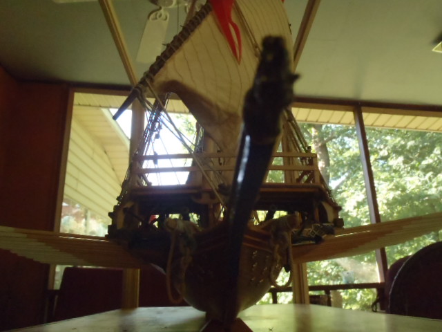
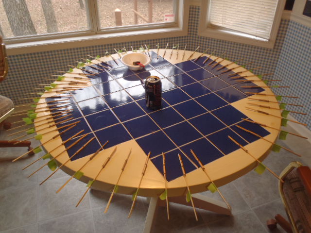
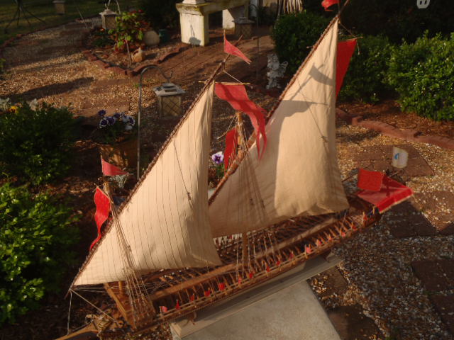
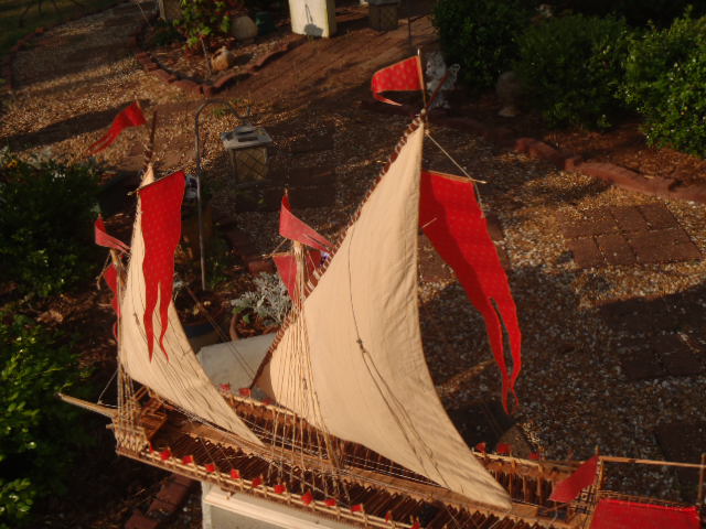
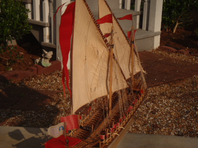
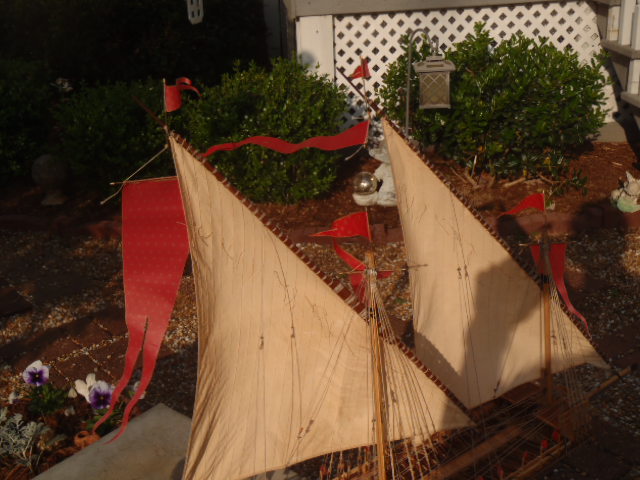
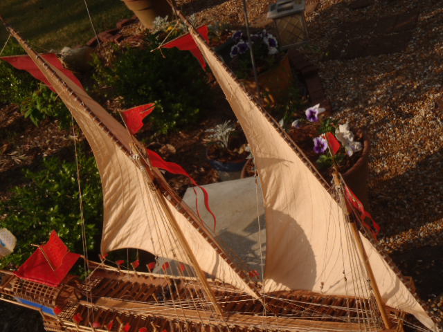
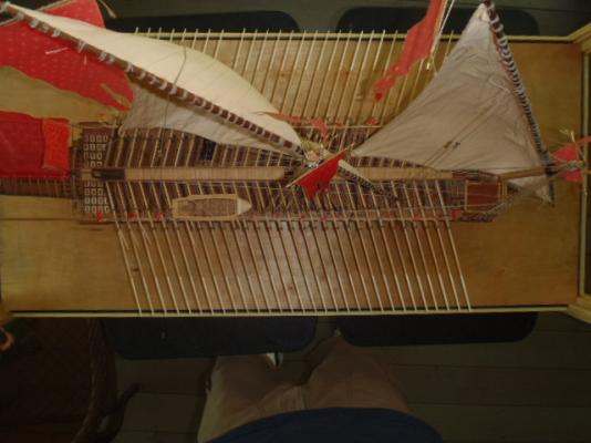
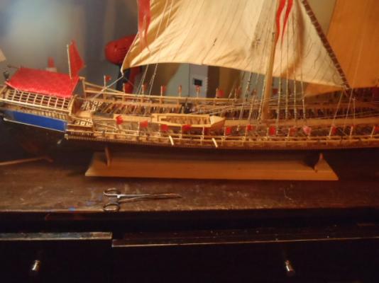
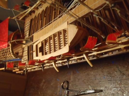
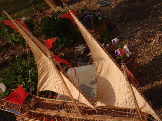
Here are some pictures I took outside. The oars are next.


- 115 replies
-
- 2
-
-
- reale de france
- corel
- (and 1 more)
-
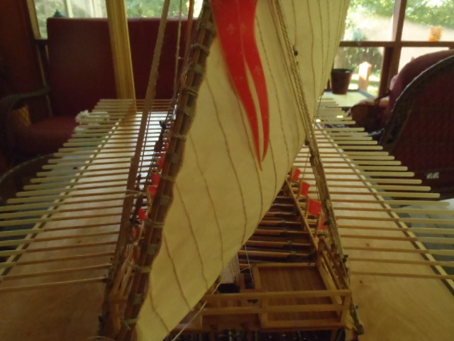
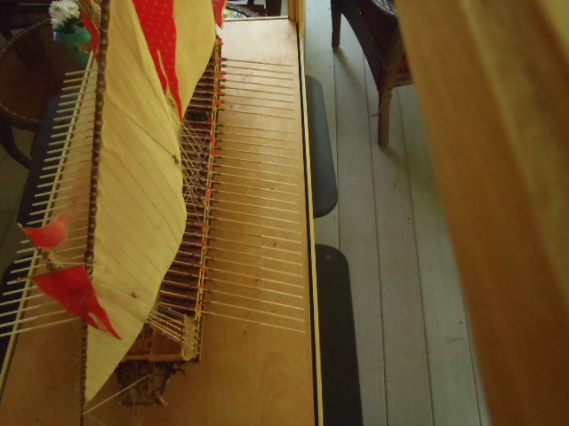
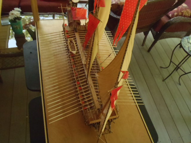
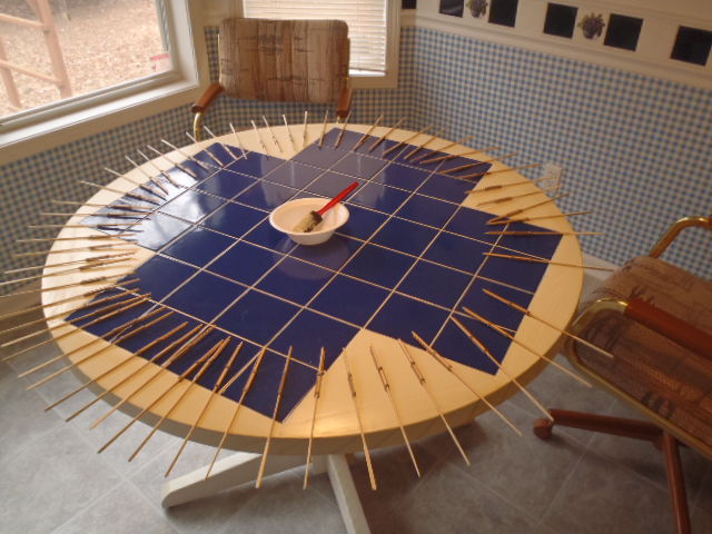
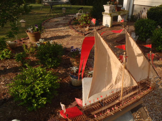
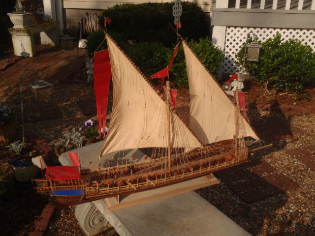
A few more pictures.