HOLIDAY DONATION DRIVE - SUPPORT MSW - DO YOUR PART TO KEEP THIS GREAT FORUM GOING! (Only 24 donations so far out of 49,000 members - C'mon guys!)
×


Bender
-
Posts
213 -
Joined
-
Last visited
Content Type
Profiles
Forums
Gallery
Events
Everything posted by Bender
-
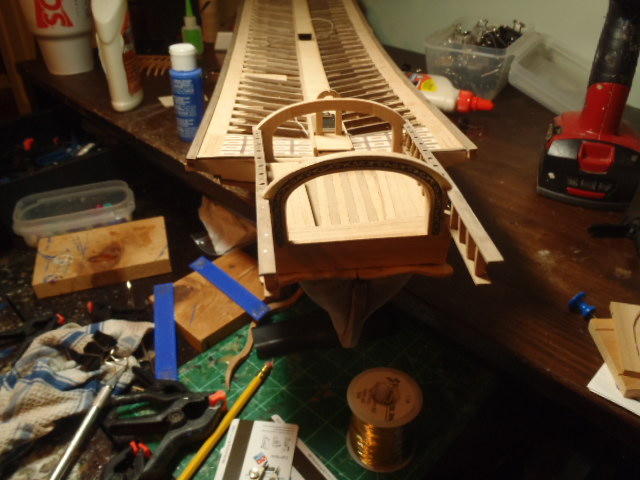
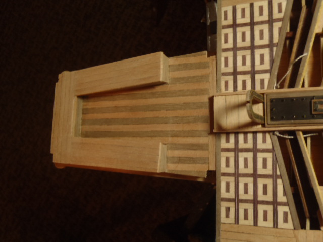
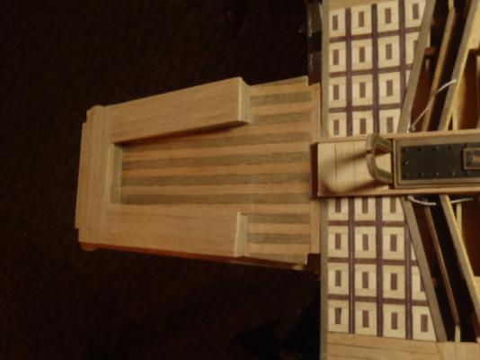
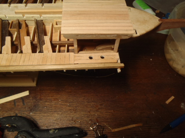
 A little backtracking and a couple of reposts. Notice that the upper side portion of the canopy sticks out past the canopy. A platform attaches to the part that sticks out. More plywood parts I used as a pattern for the platform. And the platform attached. A side note: I have no idea what the purpose of this platform was.

-
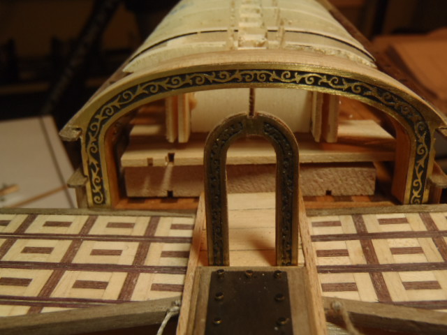
The finished canopy. More photo etched brass I attached this piece incorrectly . . . and had to remove it. It is damaged beyond repair. Rudder.


- 115 replies
-
- 1
-

-
- reale de france
- corel
- (and 1 more)
-
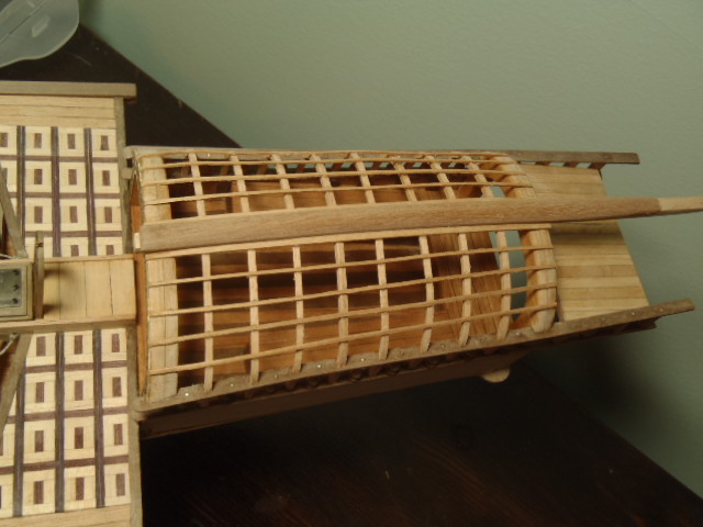
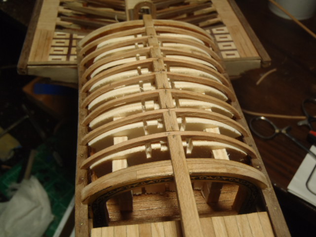
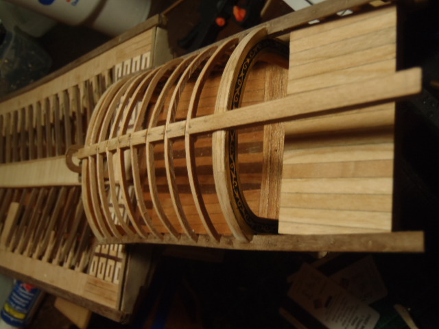
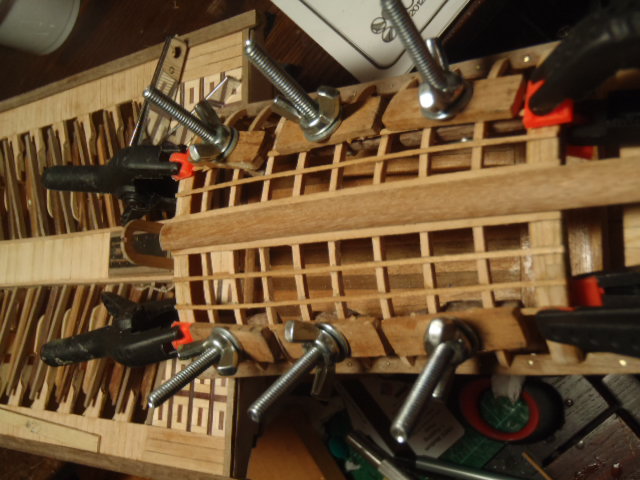
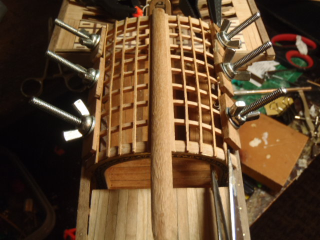
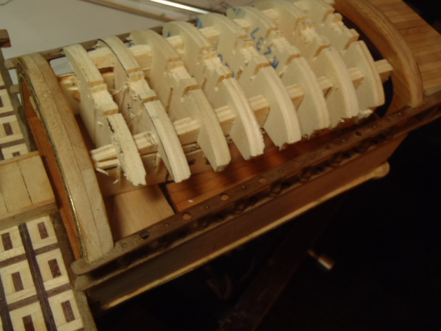
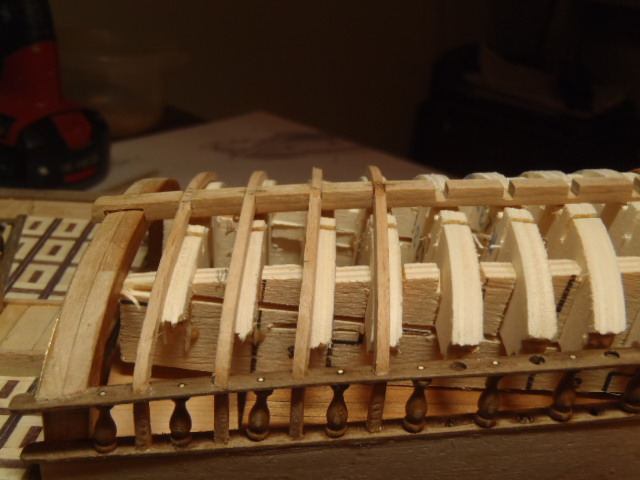
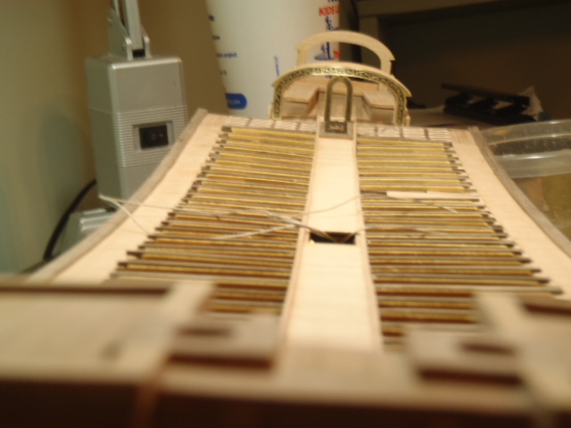
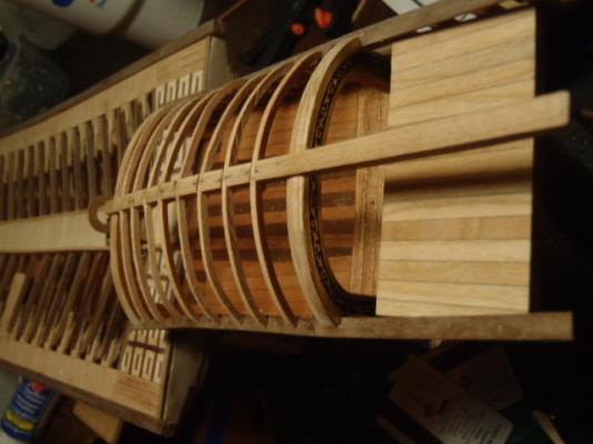
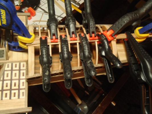
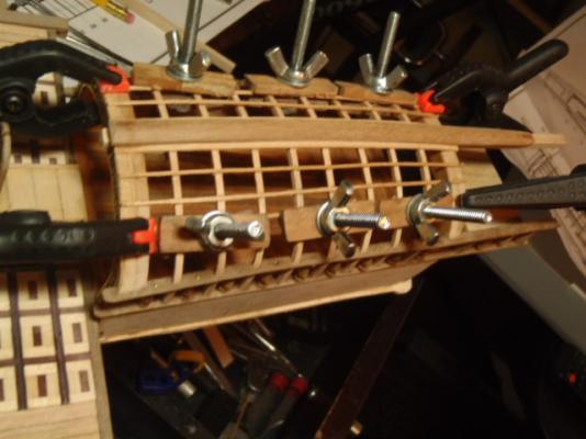
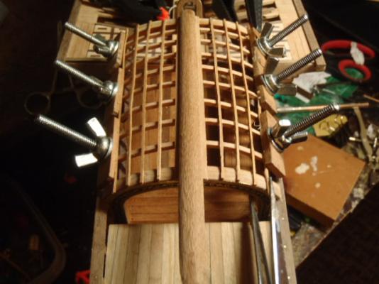
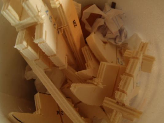
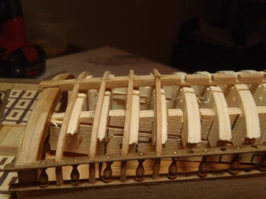
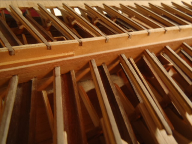
More pictures of the canopy under construction. The last of the curved slats. The form used to shape the canopy came out at this point. . . . in pieces. The next few pictures show the cross slats being attached.


- 115 replies
-
- 1
-
-
- reale de france
- corel
- (and 1 more)
-
John and Joachim, thanks very much for the kind words. I will post some more pictures tonight and maybe do it correctly.
-
Joachim, wow. You have really added a lot of details to this ship. Looks great.
-
I don't know why the pictures above are posted twice. I tried to remove the second set of picture, but if I delete one of the second set of pictures then the corresponding picture from the first set is also deleted.
-
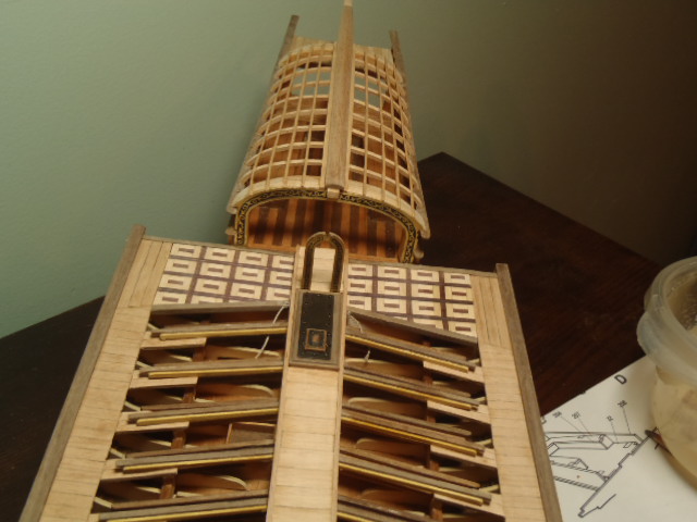
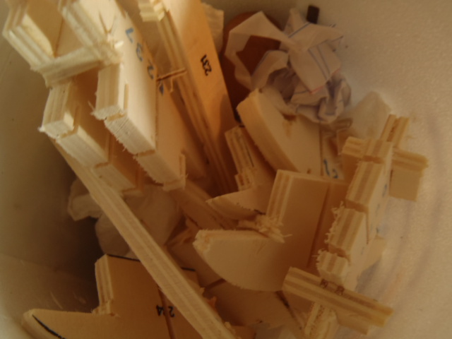
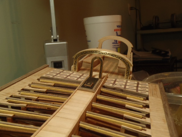
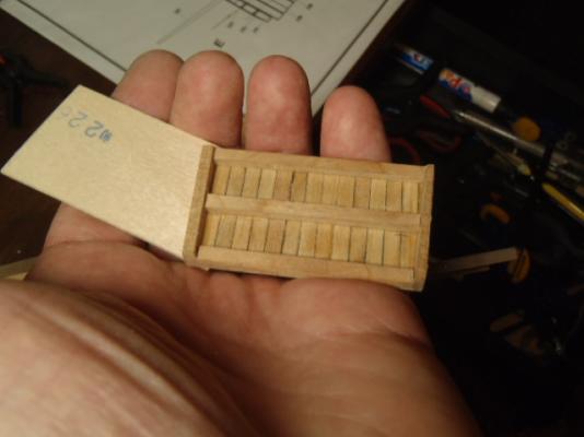
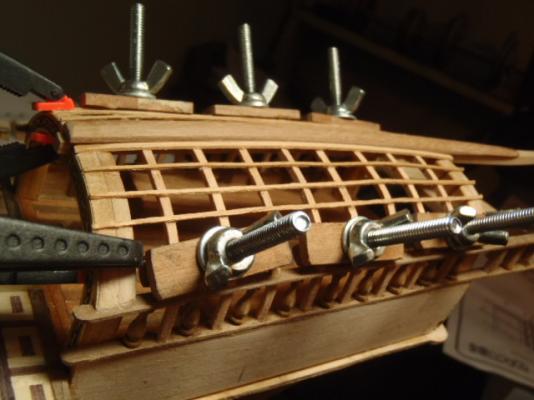
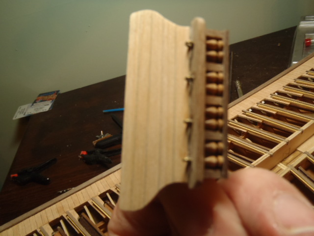
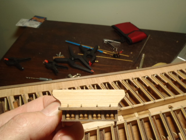
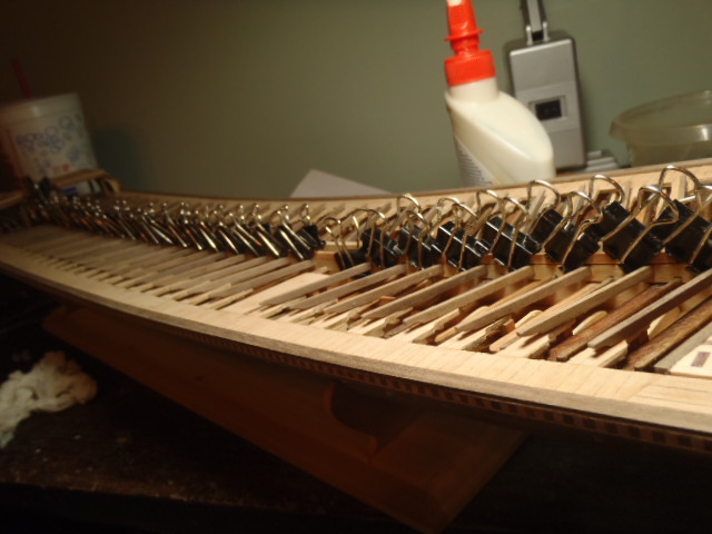
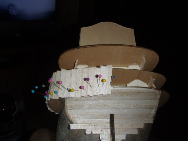
Next the canopy. The kit supplied plywood and PE brass for the lower and upper section of the walls that support the canopy. I messed up the brass on the lower section. The brass on the upper section was meant to look open with vertical spindles. I used some spindles from Model Expo and took some liberty here. You can see the plywood and the spindles. The kit supplied plywood to make a form. The slats that make the canopy top are bent over the plywood form. This form has to be remove after the canopy in finished. I made a bunch of cuts in the form to make it easier to brake apart and remove. The next few pictures show the slats being added.


- 115 replies
-
- 2
-
-
- reale de france
- corel
- (and 1 more)
-
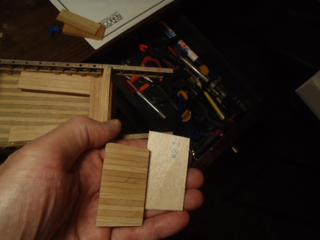
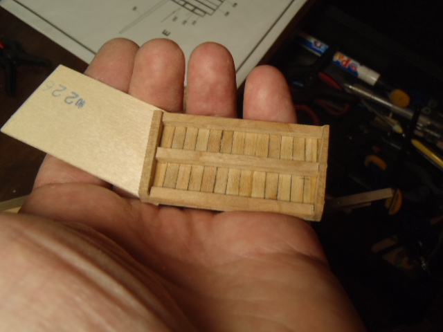
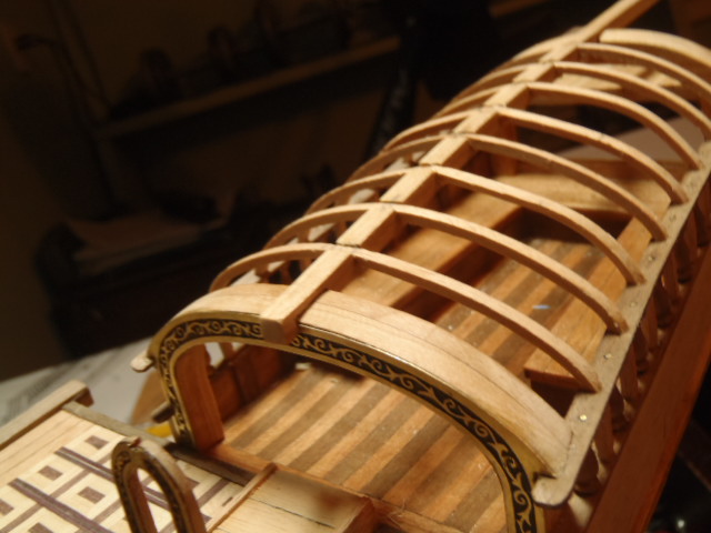
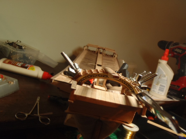
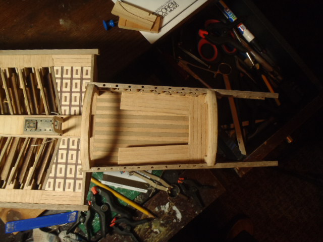
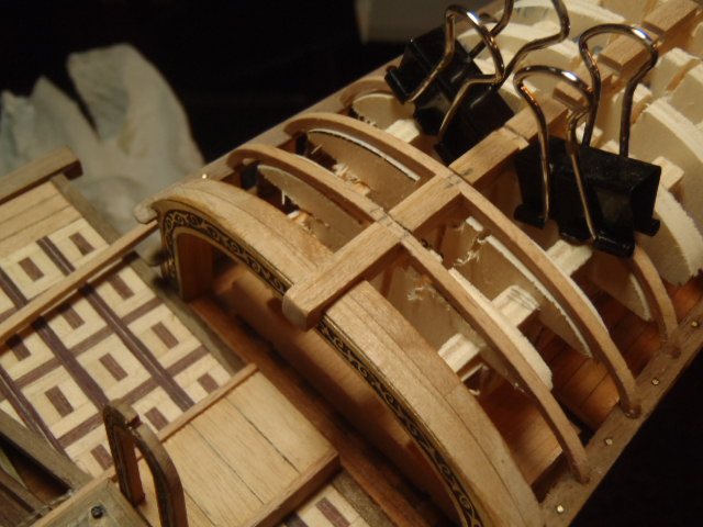
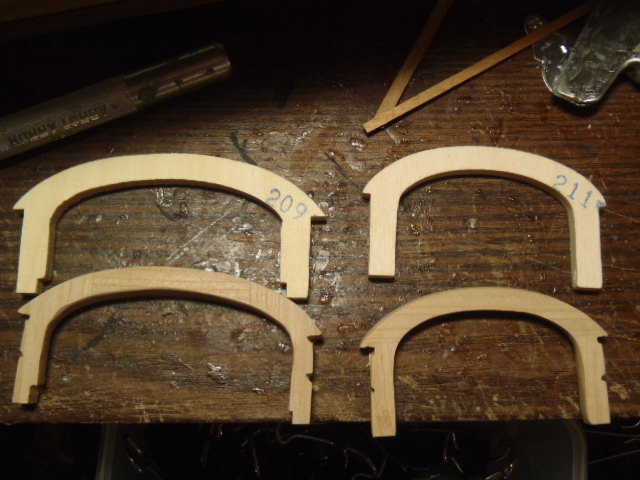
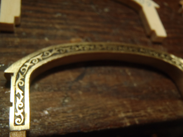
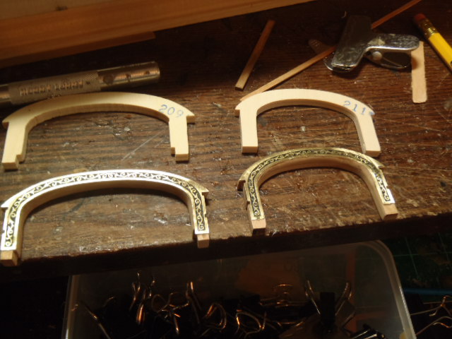
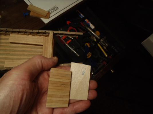
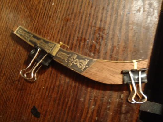
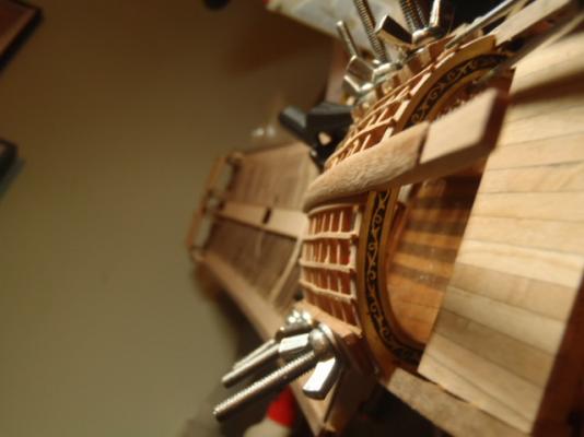
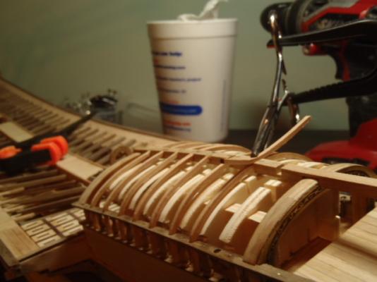
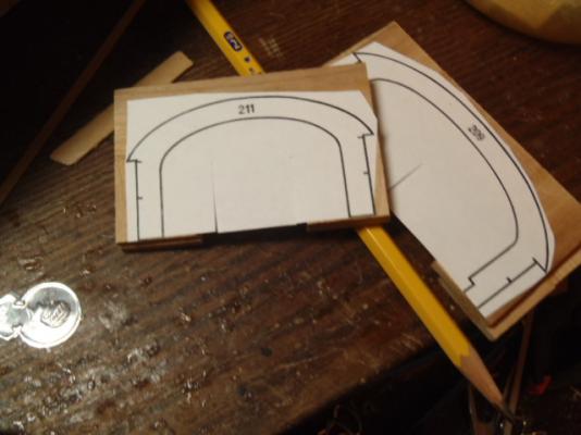
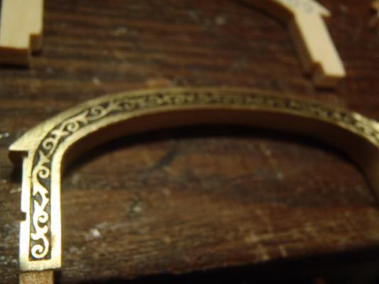
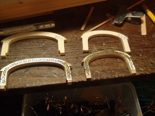
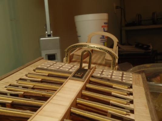
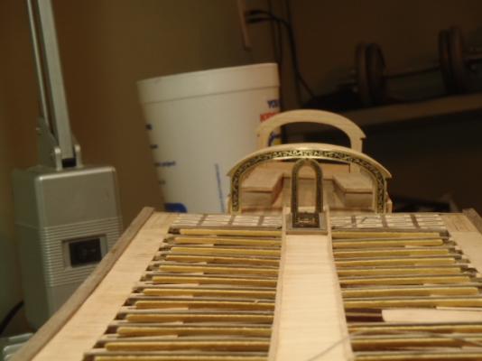
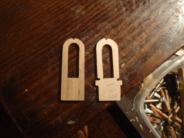
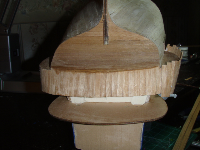
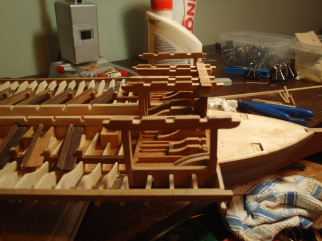
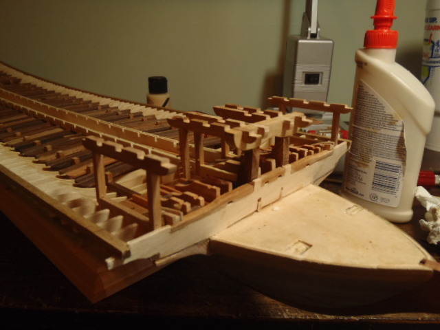
More plywood is covered. This area will have a canopy. The canopy is supported by two arches. The two arches at the top of the pictures are the kit supplied parts. You can see the part numbers. The two arches at the bottom of the picture are what I made from cherry. I made copies of the plans and made patterns for the arches. The kit supplied a lot of brass. The arches are covered on one side with etched brass. The last three picture show the arches looking back from the fore.


-
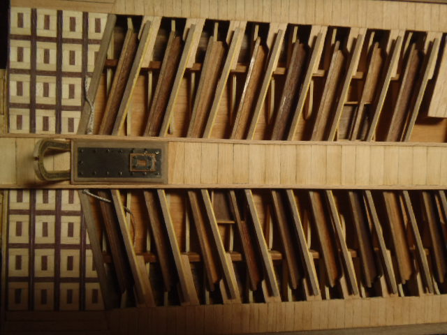
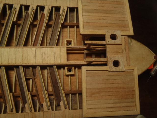
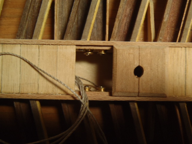
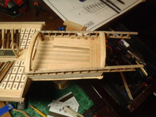
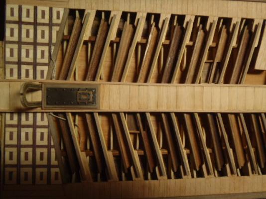
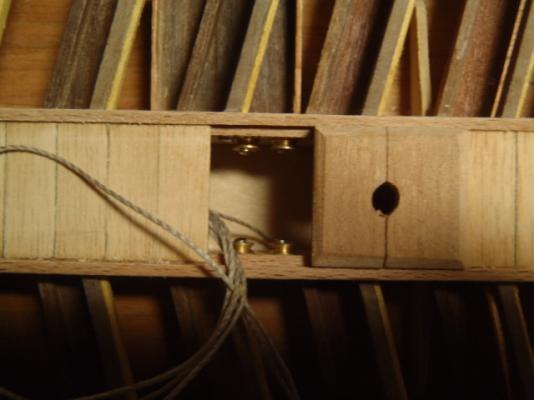
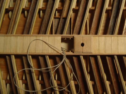
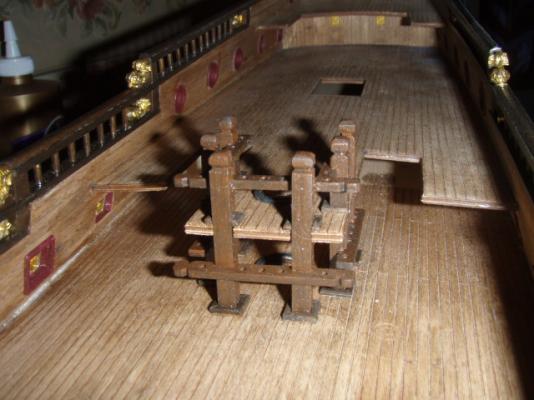
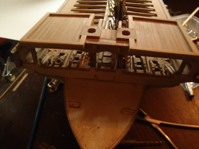
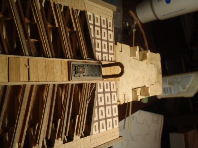
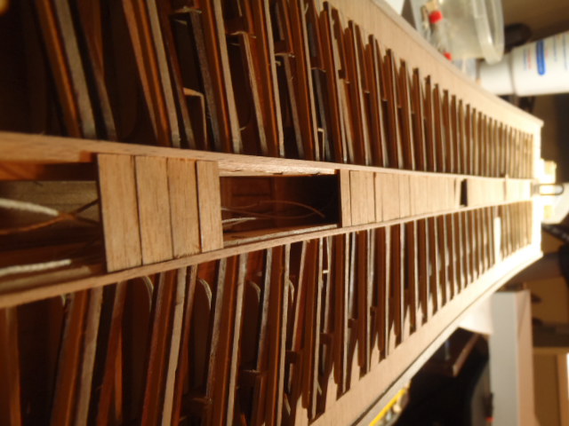
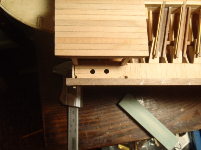
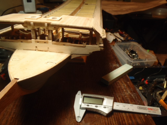
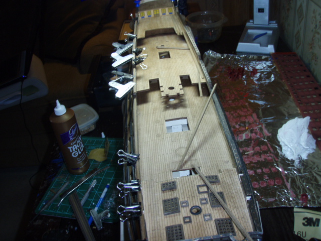
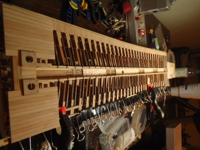
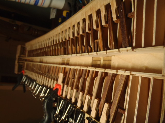
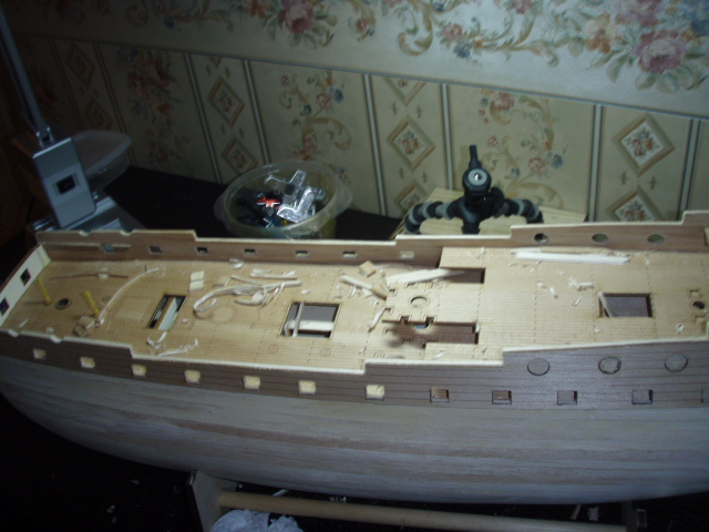
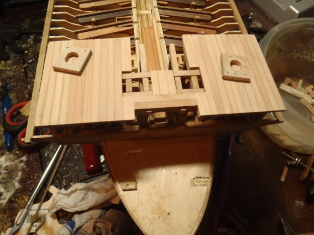
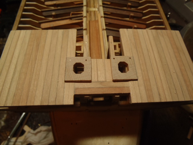
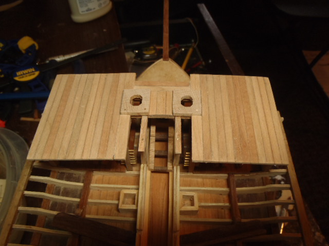
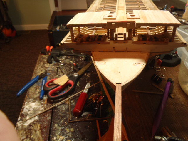
Thanks a lot guys for looking in. I really appreciate your commits. The following pictures show the finished center walkway. The main mast partners will fit into the opening left in the center walkway. This picture show the forward part of the center walkway and the raised fore castle. The anchor cable will run into the square holes near the center of the picture. The fore mast will fit into either of the two round holes (actually they are octagons) on the fore castle. The next two picture show the mast partners in place but not glued nor shaped. This is area on plywood will soon be covered.


-
Steve, here is a good picture of the laser engraved deck. I think this was after I applied a coat of a stain but thought it was too dark and ended up sanding back to bare wood.
-
Hi, Steve, and thanks for looking in. The deck is laser engraved. This is one of those models that is easier to build than what one might think.
-
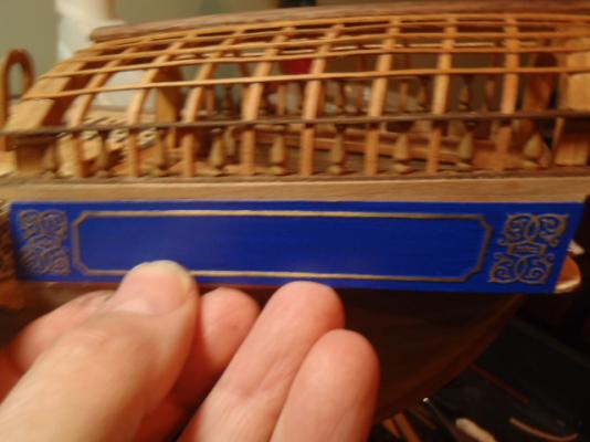
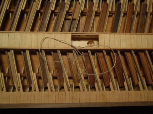
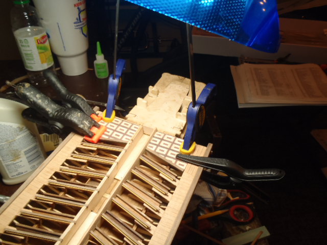
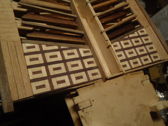
Kit supplied plywood part and part I made from cherry. The raised deck trimmed The kit supplied fancy strips for the decking in this area. Covering up the plywood on the other side. The edges and face of the plywood on center walkway are covered This shows the decking for the center walkway laying in place. The string is part of the rigging and needed to be in place before the decking is glued down.
- 115 replies
-
- 1
-
-
- reale de france
- corel
- (and 1 more)
-
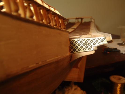
The kit came with some fancy trim. Two-hole toilet. This structure provided some privacy for the toilets. The shrouds will attach to this piece. The counter foot boards are added. I glued and clipped some wood to cover up more plywood, and you can see the counter foot boards. This shows the counter foot boards in place and shows the wood I used to cover the plywood.
- 115 replies
-
- 2
-
-
- reale de france
- corel
- (and 1 more)
-
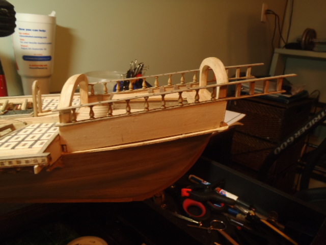
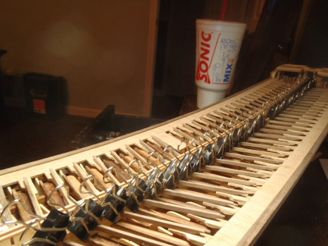
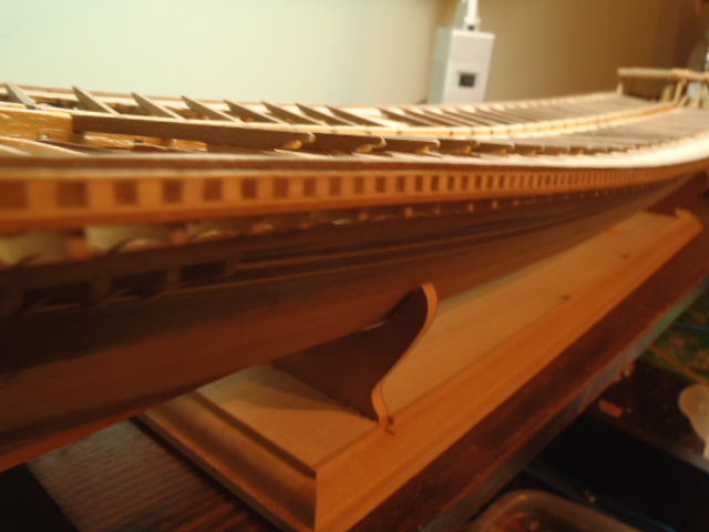
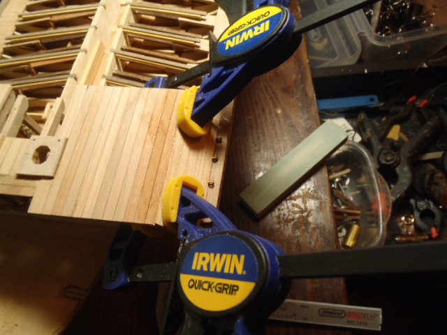
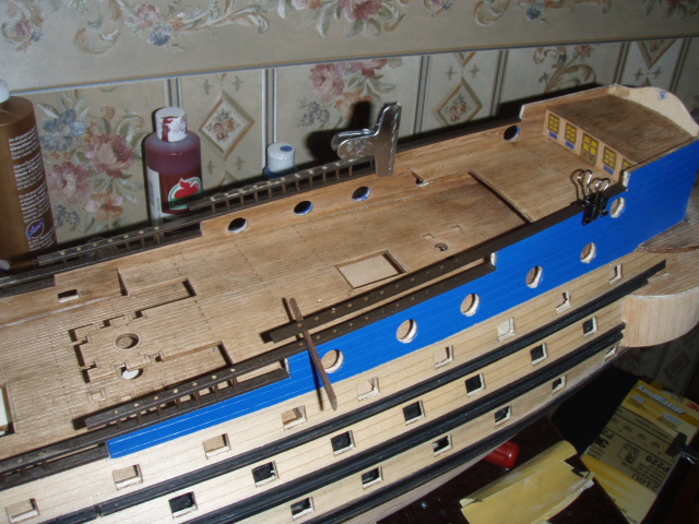
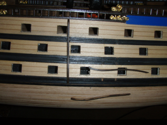
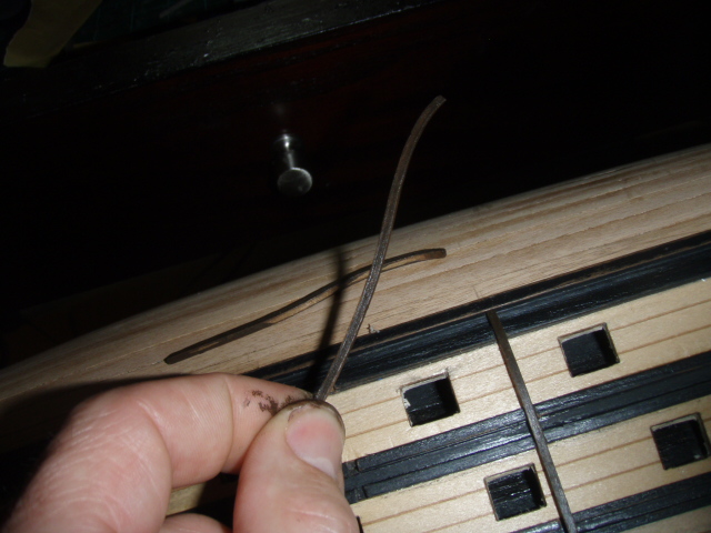
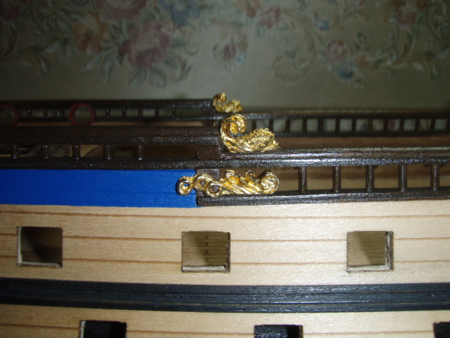
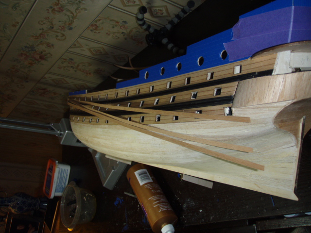
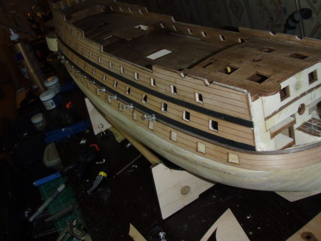
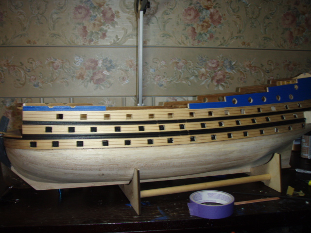
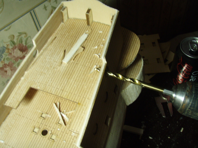
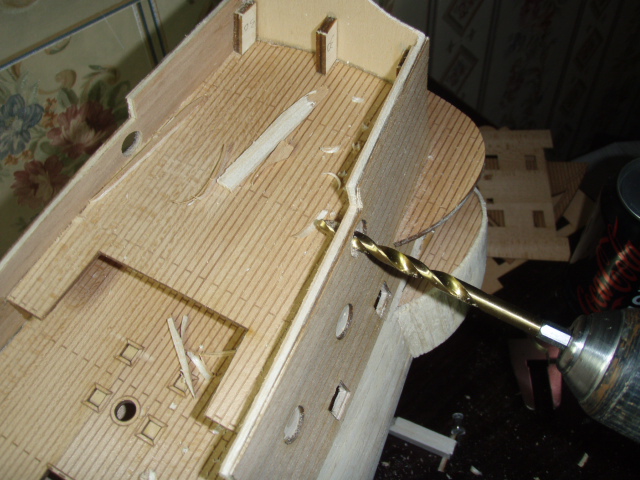
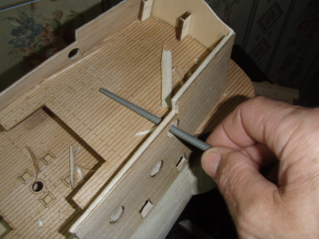
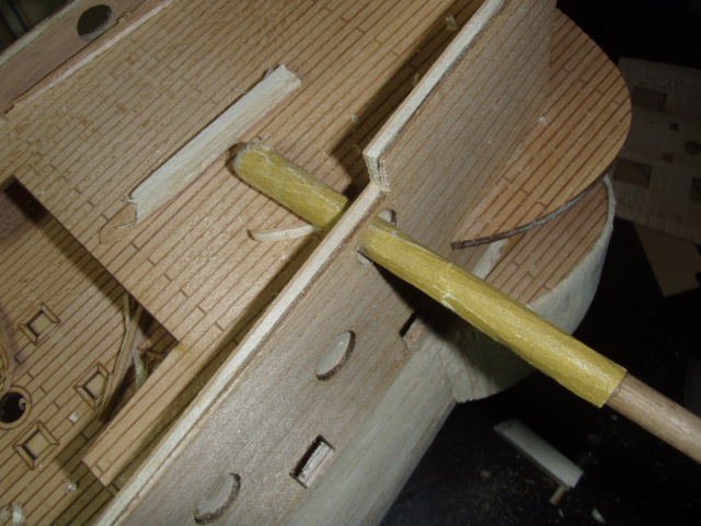
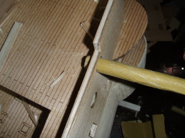
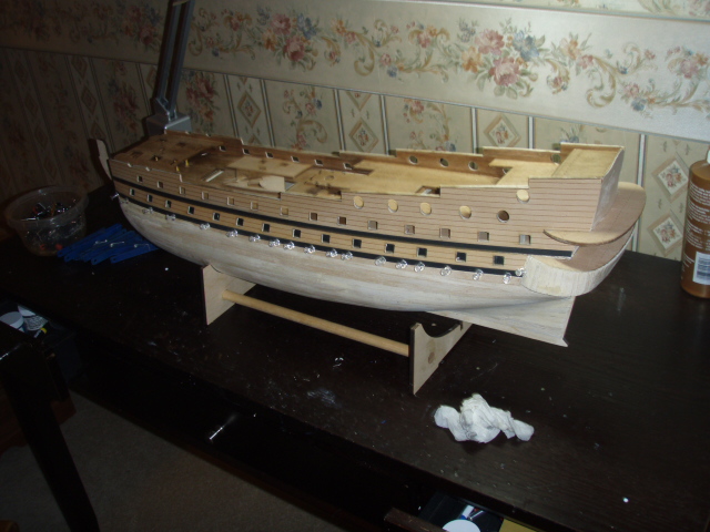
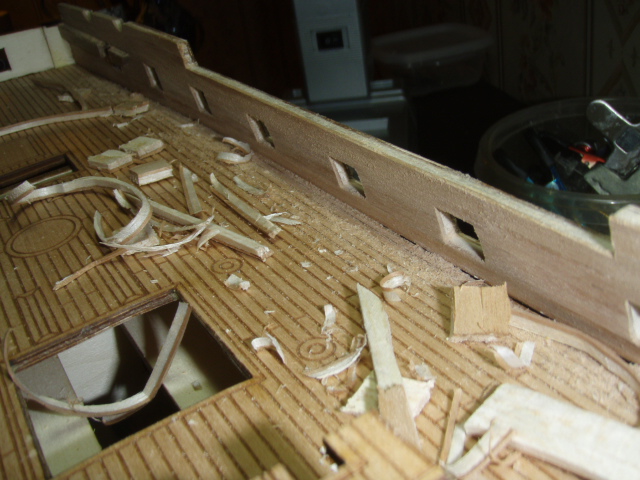
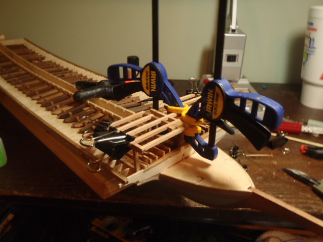
From a post originally made on May 19, 2009. This week I built and attached the gunwales. This took more time than the second planking took. I anticipated being done by Sunday. It’s Tuesday. The hardest part (not really hard but time consuming) was sanding and filing the upper and lower part of the rail to take in the four round gun ports. The rail is of four parts: a bottom strip, 2 mm dowel place vertically, a top strip, and then a half dowel is attached to the top strip. To make the half-dowel, I taped two 2x4 mm walnut strips together, stuck this in my drill and gave it a spin while sanding. And I attached the vertical strips that the ship’s boat would slide up and down when put into the water. Next, I going to work at the bow of the ship. In this picture you can see where the bulwark and the top rail has to be shaped to fit the round gun port. The bottom and top rail are first cut to size and placed. The rail is marked where the hole are to be drilled. The holes are drilled through the top and bottom rail at the same time. This helps to assure the vertical pieces are parallel to each other. Then the bottom rail is attached. When the glued dries the dowel pieces are glued in place. I used pieces of scrap placed between the top rail and the bottom rail to maintain equal distance between the rails. After the glue dried I sanded the top face of the top rail to flush up any dowel that was sticking up too much. Last I attached the half dowel on top of the top rail. The pieces laying across the deck are the half dowel These last pictures show the bumper rails
-
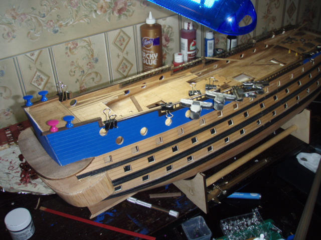
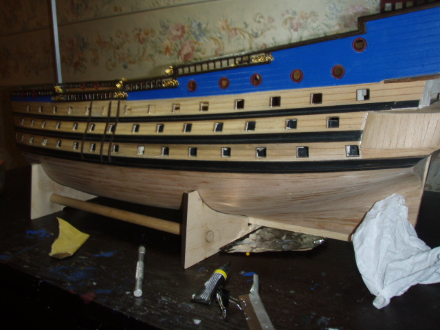
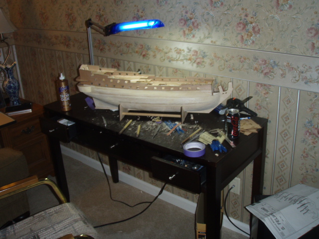
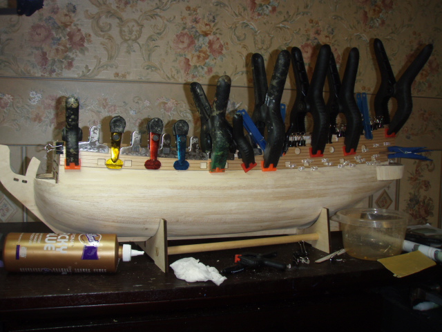
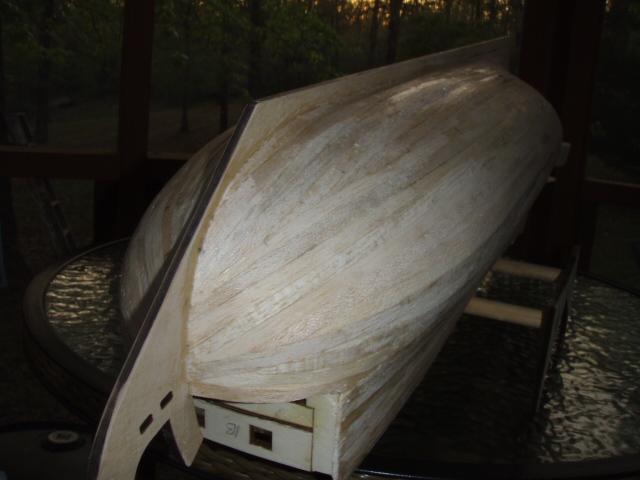
From a post originally made on May 16, 2009. The second planking went well. The directions said to plank with 1x7 walnut. The kit had a bundle of twelve 1x7 strips. It had several 1X6 strips, but not enough to plank the hull, so the hull is planked in both 1x7 strips and 1x6 strips. It took 22 more strips each side below the third roll of gun ports. I am still happy with the kit, but the instructions fall short. When I say fall short, I mean fall short in both quality and quantity. The directions just end at making the tops. I emailed Mantua, and Mantua said they would mail me the updates when available. So that made me realize: “Mantua revised this kit and sent it out without having the direction ready?” I finished San Felipe nearly 4 years ago and still have not received the update. Here are some pictures of the second planking.
-
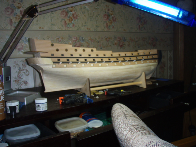
A few more pictures. The planking at the lower gun deck. Some paint applied.
-
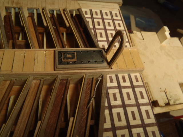
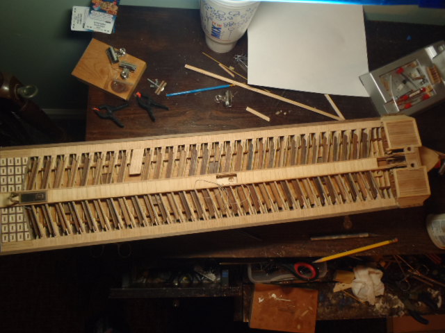
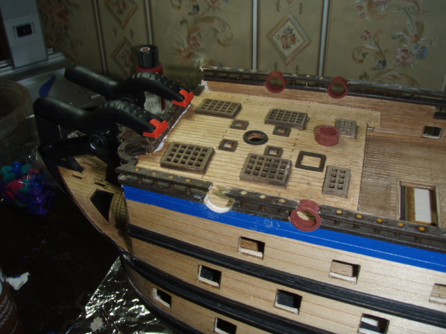
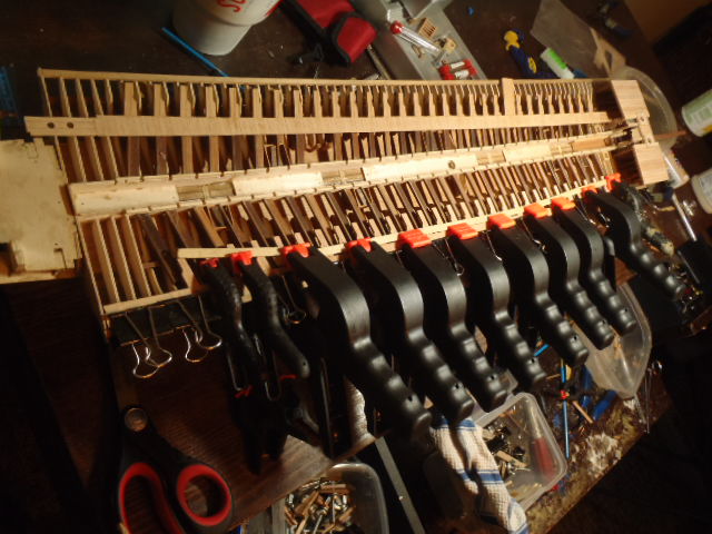
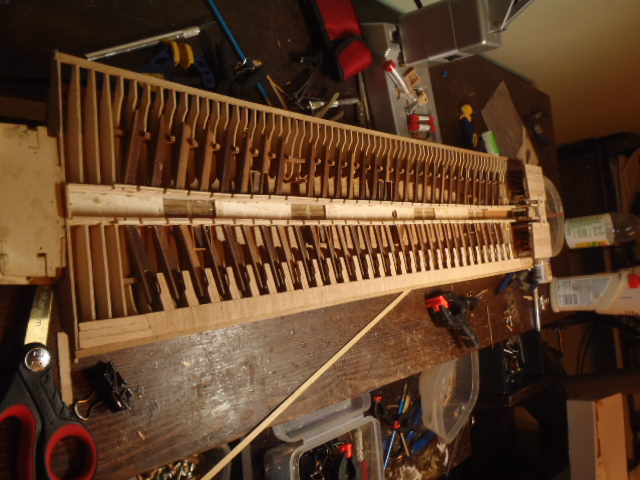
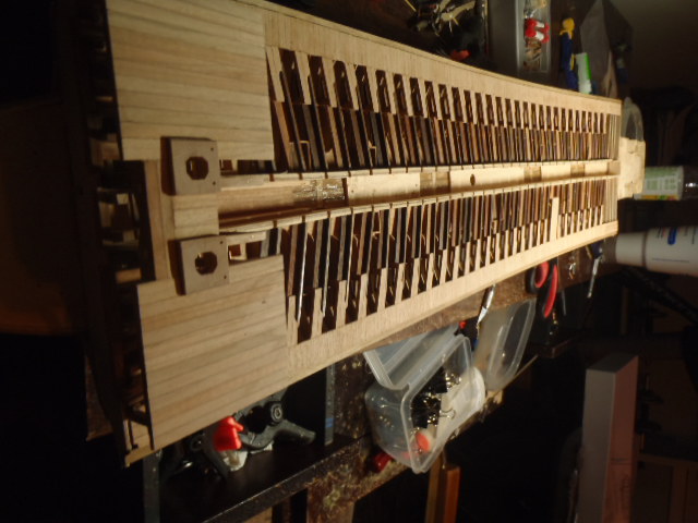
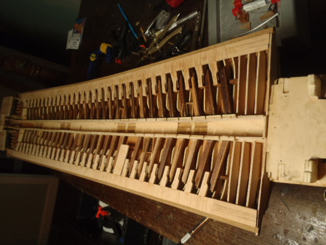
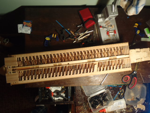
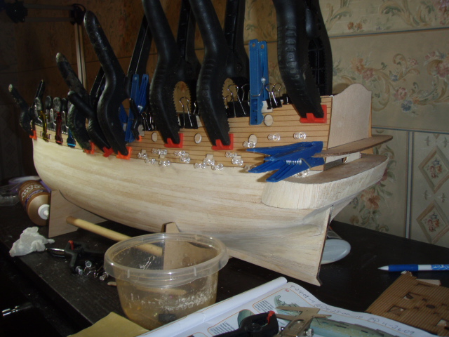
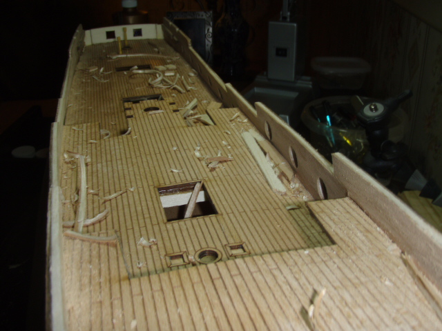
This ship has three walkways. One down the center and one on each side running the length of the overdeck. These pictures show the port and starboard walkways. Starboard side walkway being clamped to the overdeck. The curved piece you see under the clamps is there to keep the clamps from damaging the wood. Clamps removed Close up of the walkway and raised deck. The two round holes are the deck officers' toilets. The port side walkway under the clamps. The perspective of the starboard side (tops of picture) makes it seem that the walkway and the raised deck are on the same level. They are not. Perspective is off on this picture too.
- 115 replies
-
- 2
-
-
- reale de france
- corel
- (and 1 more)
-
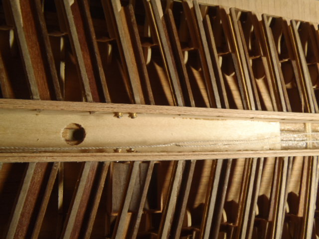
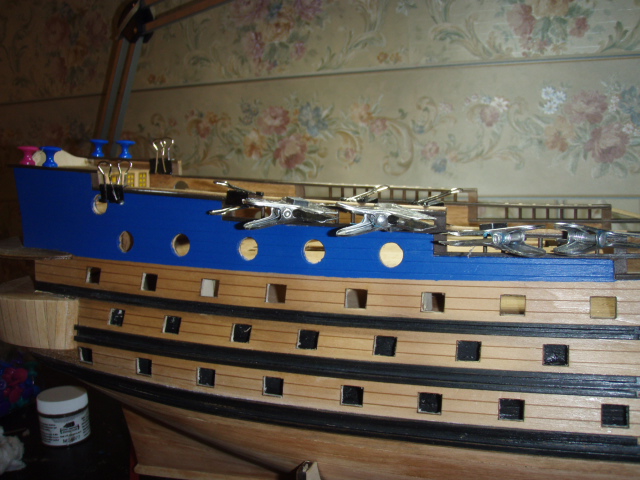
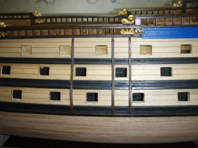
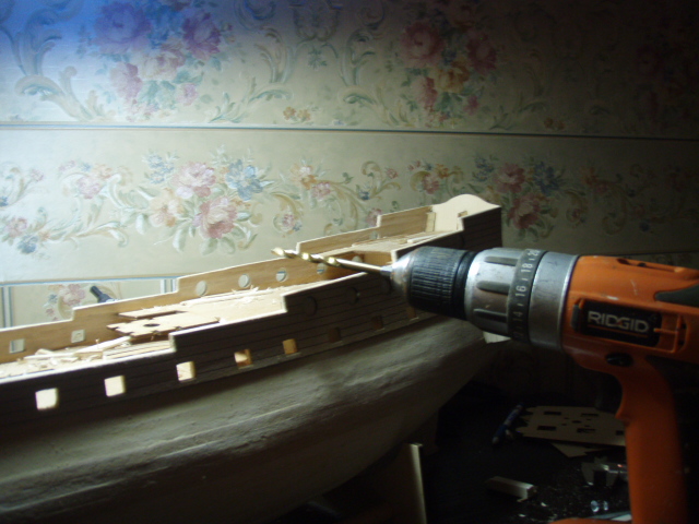
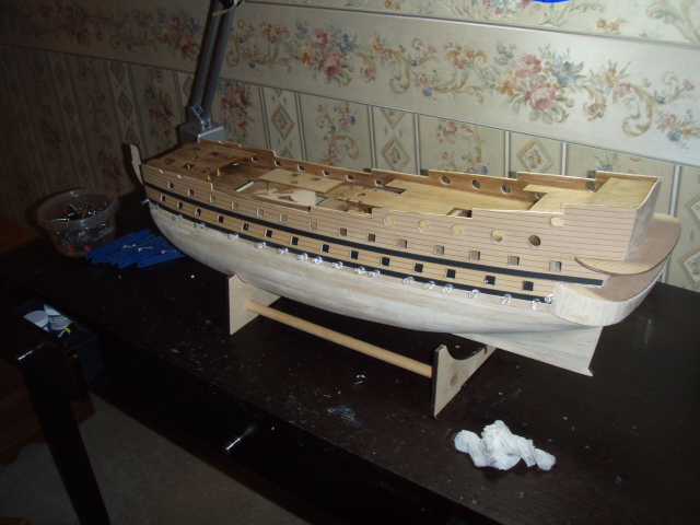
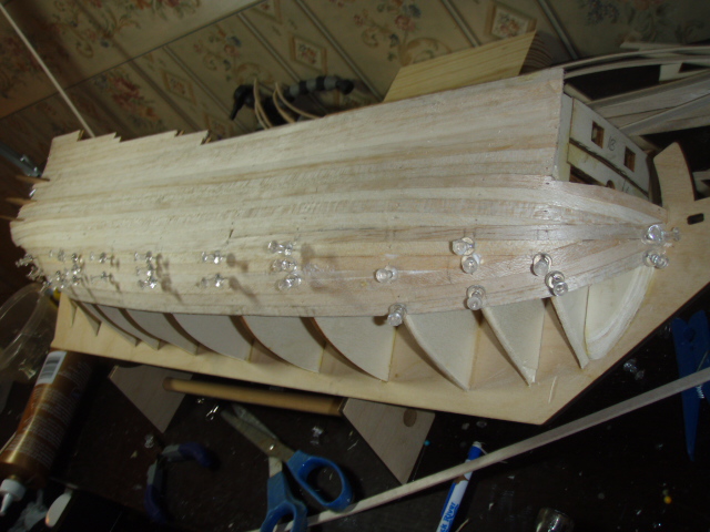
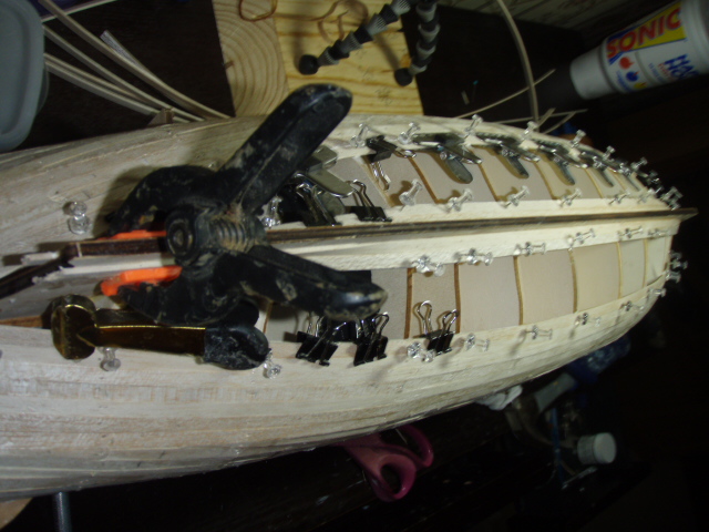
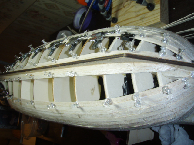
From a post made on May 9, 2009. For the round holes I first drilled a hole in the center, second I filed the hole bigger, third I used a piece of 8mm dowel with sandpaper glued around it to make the hole bigger, and fourth I used a piece of 10mm dowel with sandpaper to finish rounding the hole to size. I worried too much about the gun port in my pervious post. Back to the planking ply. The top run of planking ply is attached first. I measured and rechecked my measurement three times just to make sure I placed it in the correct spot. Then a single 1x6 walnut strip with two 2x2 walnut rubbing strakes were attached. The second run of planking ply went on followed by a single 1x6 strip and two 2X3 walnut rubbing strakes. The third run of planking ply had to be bent around the bow. It did not want to bend. I was afraid if I heated or dampened the strip the plies would separate. I finally gave in and heated the strip—and the plies did separate. This worked out okay. The strip bent easily, and after gluing the plies back together, the strip held it curved shape. Next, I will start the rest of the hull planking. It will take 20 strips on each side to finish the hull. Drilled a hole first Filed the hole bigger. 8mm dowel with sandpaper glued around it to make the hole a little bigger 10mm dowel with sandpaper to finish rounding the hole to size. The next two pictures show what it looked like with the first strip of planking plywood. The next two pictures show what it looked like with two strips of planking plywood and the two rubbing strakes.
-
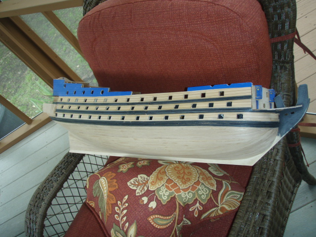
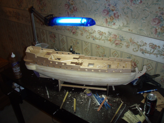
This is from a post made on May 9, 2009: The second planking begins. The second planking from the gun port up is laser engraved plywood. Walnut strips will cover the hull below the gun ports. Each strip of planking plywood is 18 mm wide or wider and is engraved to look like three or more planks. The gun ports are laser cut so that each strip of planking plywood serves as a template to cut the gun port hole. For the 62 ports below the decks, I had only the first planking of balsa to cut out. Those ports gave me no trouble. For the ports above the decks—which includes the round ports—I had the balsa and the walnut strips along the inside of the bulwarks to cut out. The rectangular ports went well enough. I went through several exacto blades. The first strip on planking plywood clamped Clamps off A view of deck. Note the deck planking is also finished at this point. I'll talk about that later.

-
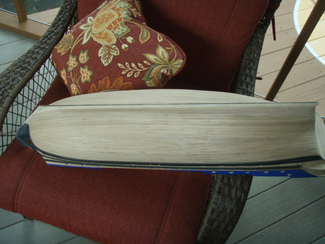
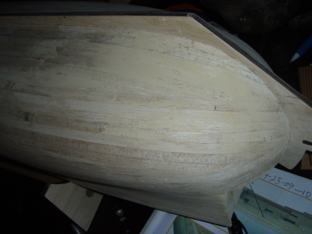
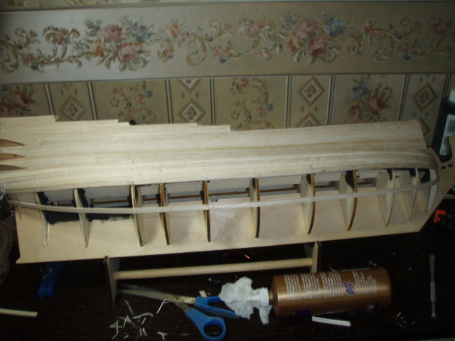
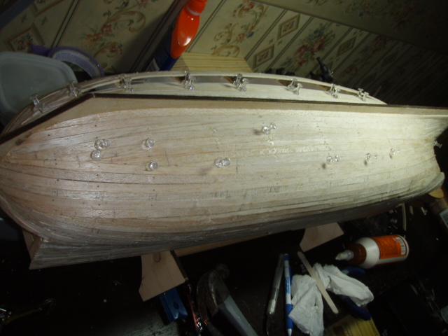
This is from a post made on May 2, 2009. I spent a few days sanding the high spots and puttying the low spots. After finishing the first planking of balsa I sanded the hull down, and then following the Mantua direction, I coated the entire hull with a mixture of white glue and water 30/70. This made the hull a little more firm. The glue/water mixture seems to soak into the balsa wood. Then I scraped some putty in the low spots, sanded the entire hull again, putty a few more low spots, and then sanded one more time. Next is cutting the handrail profile and cutting the 86 rectangular, 12 circular, and 4 semicircular gun ports. Later there will be 2 more gun ports at the bow and 4 under the curve of the stern to cut.
-
Sherry, it is good to see you off and running with San Felipe.
-
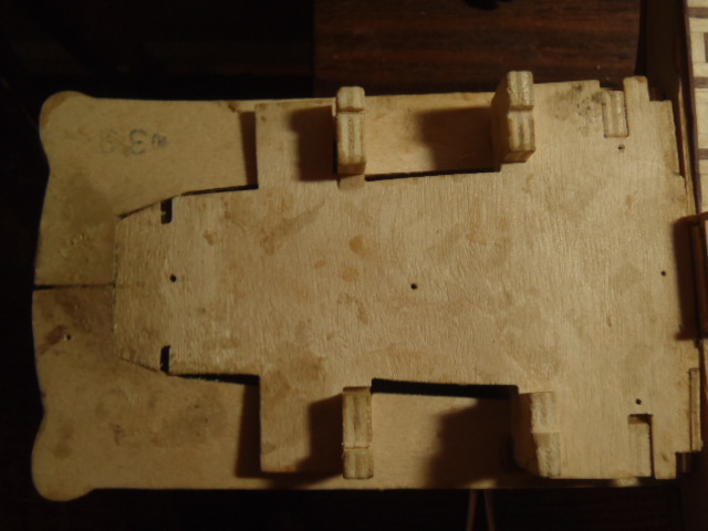
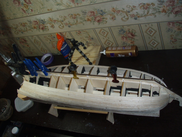
Now that the keel and stems are permanently attached, I re-assembled the raised fore castle deck.
- 115 replies
-
- 1
-
-
- reale de france
- corel
- (and 1 more)
-
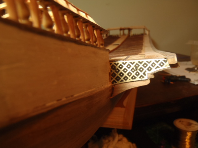
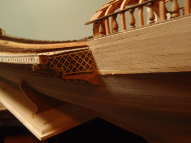
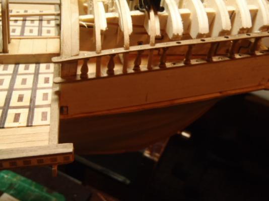
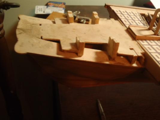
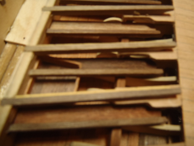
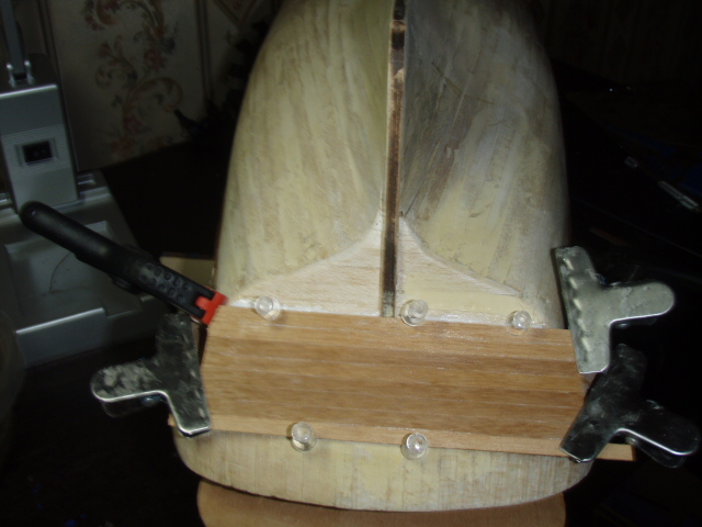
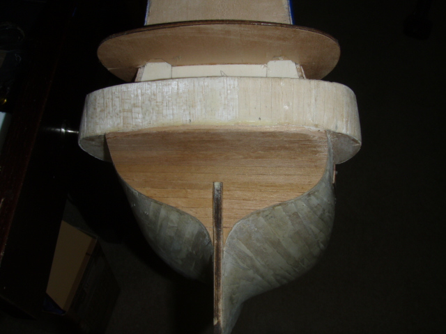
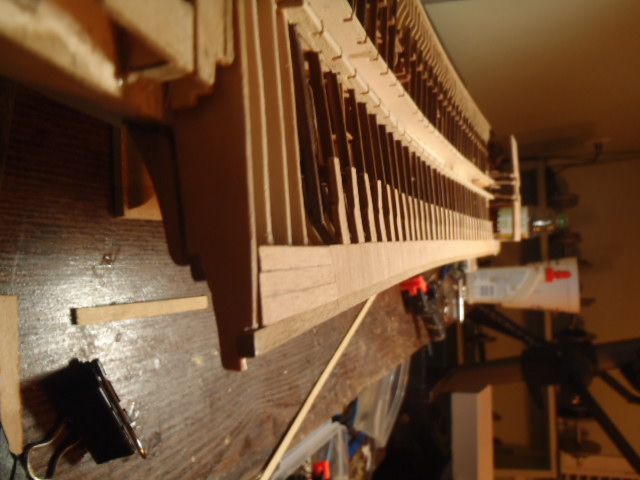
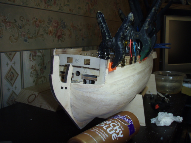
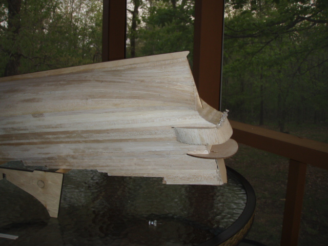
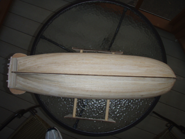
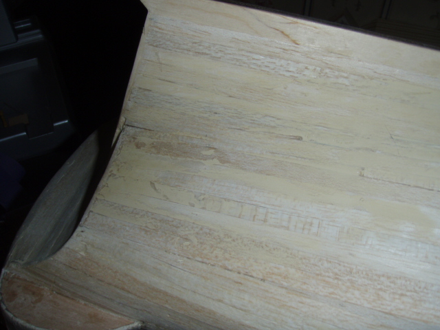
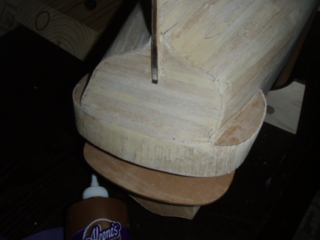
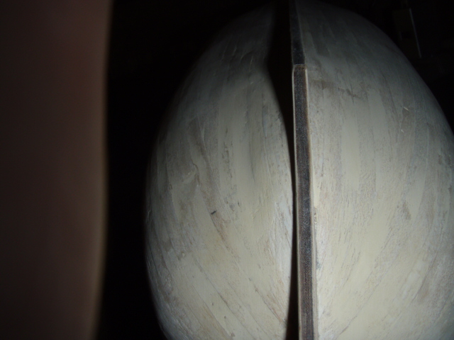
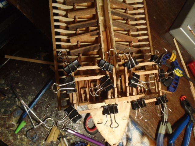
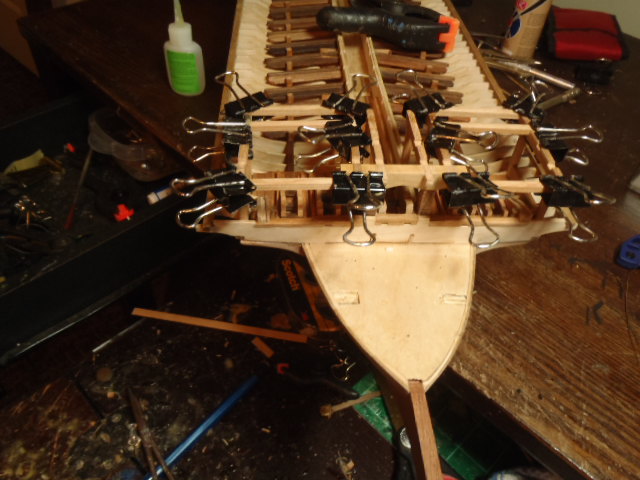
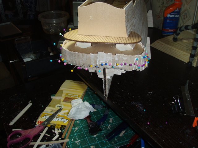
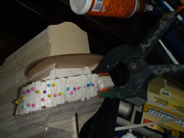
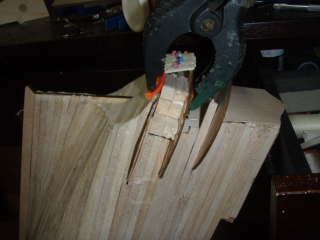
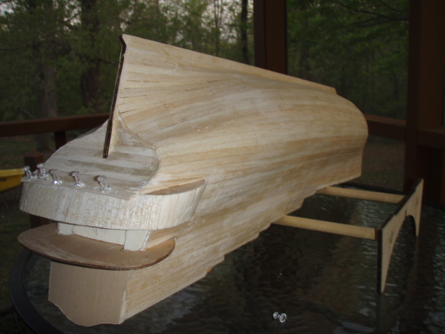
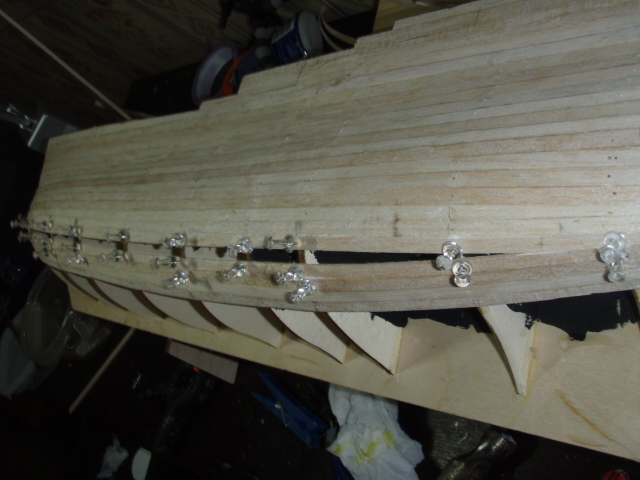
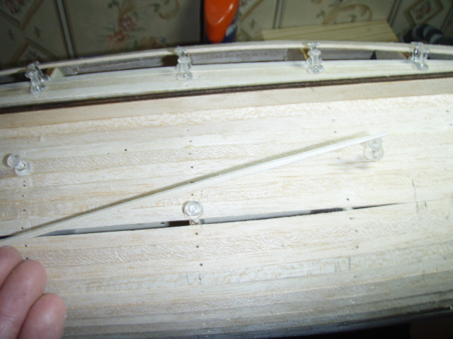
This is from a post made of April 26, 2009. I had my first major take apart and redo on The San Felipe. At the stern of the ship there are three thin plywood flaps that stick on like tailfins of a fish. The top two are terraces. Planking is laid vertically between the middle and bottom flaps, so that the bottom flap would be part of the ship’s interior. (Maybe the officers’ toilet facilities???) I glued about fifty pieces of balsa and when the glued dried, I trimmed of the excess balsa. This is when I noticed the problems. (Sorry no pictures of this foul up. The last thing on my mind was taking pictures. I was thinking what the ding dang did I do wrong?) When looking at the ship from the rear, the vertically planked area between the middle and bottom flaps was wider from top-to-bottom on the right than the left. I couldn’t tell if the bottom flap was drooping or if the middle flap was getting higher. After measuring I realized it was a little of both. I took off all the vertical planks and glued balsa blocks between the middle and bottom flaps and clamped. This took care of the drooping bottom flap but the middle flap pulled loose from the balsa and arched back up. The left side was okay, so I re-planked just past center. Again I clamped the middle and bottom flaps together, but this pulled the bottom flap up instead of pulling the middle flap down. I always think clamp together, never push apart, but pushing apart was the answer. I wedged some scrap between the top and middle flaps. There is a picture of this below, but it is hard to tell the scrap from the ship’s frame. With the middle flap down where it was suppose to be, I finished gluing the vertical planks. The scrap wedge stayed in until the next day. I wanted to make sure the glue was dry. I also had to remove one plank from the curve under the stern and replace it after the vertical pieces were trimmed. Vertical planks between the middle and bottom flaps. (Before seeing the foul up.) All of the vertical strips were removed. The flip was held in place while the left side was re-planked. I filled the gap with more balsa blocks and clamped. When I remove the clamp the flap pulled loose. Notice the piece of scrap (it appears whiter than the other wood) wedged between the top and middle flaps. This piece of scrap is holding the middle flap down while the glue dries on the vertical pieces of planks. Trimmed and sanded aft end. Also showing the replaced plank under the curve of the stern.
-
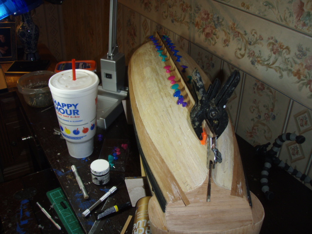
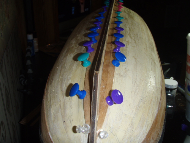
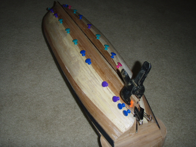
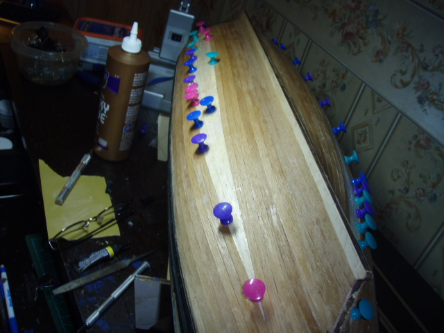
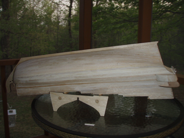
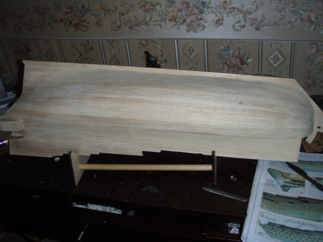
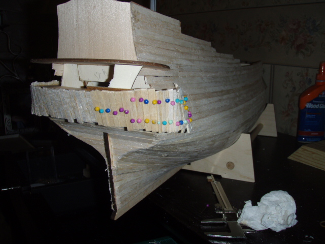
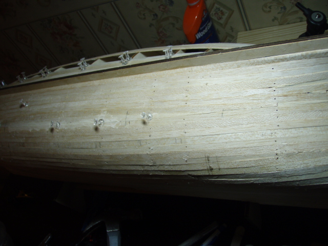
This post was originally made on April 25, 2009. The first planking is well underway, and I have stayed with the kit’s directions. As mentioned to Chrism in the previous post, I am using balsa for the first planking. The balsa is easy to work with: easy to cut, easy to bend, easy to trim to the needed shape. I did have one problem with the balsa when I was building the Royal Caroline. I used map pins to hold the second planking of walnut against the balsa, but the balsa was too soft in a few spots to hold the pin in tightly. It was not a big problem. CA glue took care of it. Back to the San Felipe. I lack under the curve at the stern and the vertical pieces under the lower terrace at the stern. After that, a day or two of sanding awaits me. Then the part I am dreading: cutting the profile of the handrails and cutting the cannon ports. Later on I had to remove these vertical pieces.
-
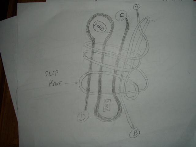
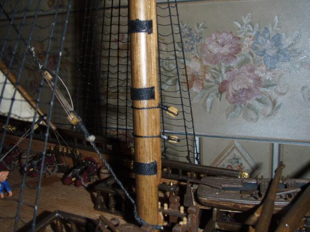
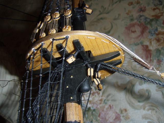
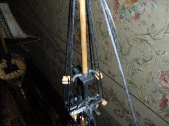
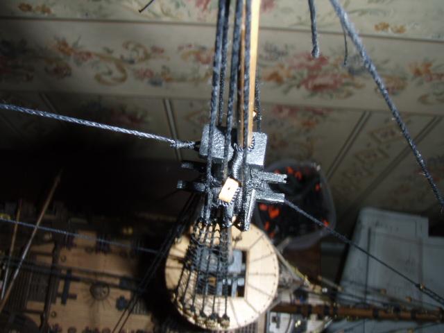
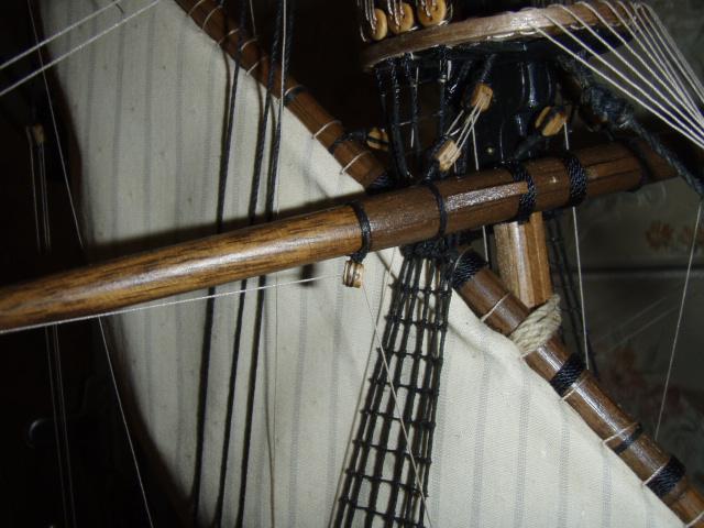
I am not very good at drawing but . . . The last four pictures shows different places I have used this method. Around a yard. Under a top. These blocks were added by passing the thicker thread around the cross tree before doing any warping. All of these blocks are attached with this method. I used a variation of this method to attach the stay. And one more I lied. One more.
- 8 replies
-
- 15
-