Hubac's Historian
-
Posts
3,317 -
Joined
-
Last visited
Content Type
Profiles
Forums
Gallery
Events
Everything posted by Hubac's Historian
-
 Can you please remind me what your lower deck port opening width and height are in MM? I’m assuming that the white framing are the port lid stops, and that you will plank up to and around these? Also, what is the distance between openings in MMs?
- 452 replies
-
- 1
-

-
- soleil royal
- Heller
- (and 1 more)
-
In fact, I didn’t catch it in post #428, but your layout there actually shows 17 piercings, including the bow chase port. Should be 16 in total.
-
As far as creating a more compressed impression between gun decks, I think you are succeeding, there. What has me confused about your layout is that you show 16 lower deck piercings (red squares), but the forward chase port is in the position of a broadside gun - too far aft, in other words. This has implications for the layout of all gun decks above.
-
I’m going to let this sit as well. Gotta really focus, and I’m not quite where I want to be.
- 452 replies
-
- 1
-
-
- soleil royal
- Heller
- (and 1 more)
-
Before you start cutting, might you want to be sure of the stagger pattern for your middle deck guns, and where that will all map out for the upper main deck guns?
-
Voila! And, I also agree that going back to 9MM ports will be appropriate.
-
Try increasing the spacing between ports 2 - 15 to 22 MM, this will be just under .875 imperial, or 7 scale feet at 1:96. Your current spacing looks a little crowded, and the space between the bow chase port and the next gun aft is too large. You are trying to impose 1671 dimensional parameters on a kit based off of 1693 dimensional parameters. It doesn’t have to “be” exactly right. It just has to look right.
-
At scale, if you end up in the vicinity of 6.5 - 7’ between ports, then that’s where you want to be.
- 452 replies
-
- 1
-
-
- soleil royal
- Heller
- (and 1 more)
-
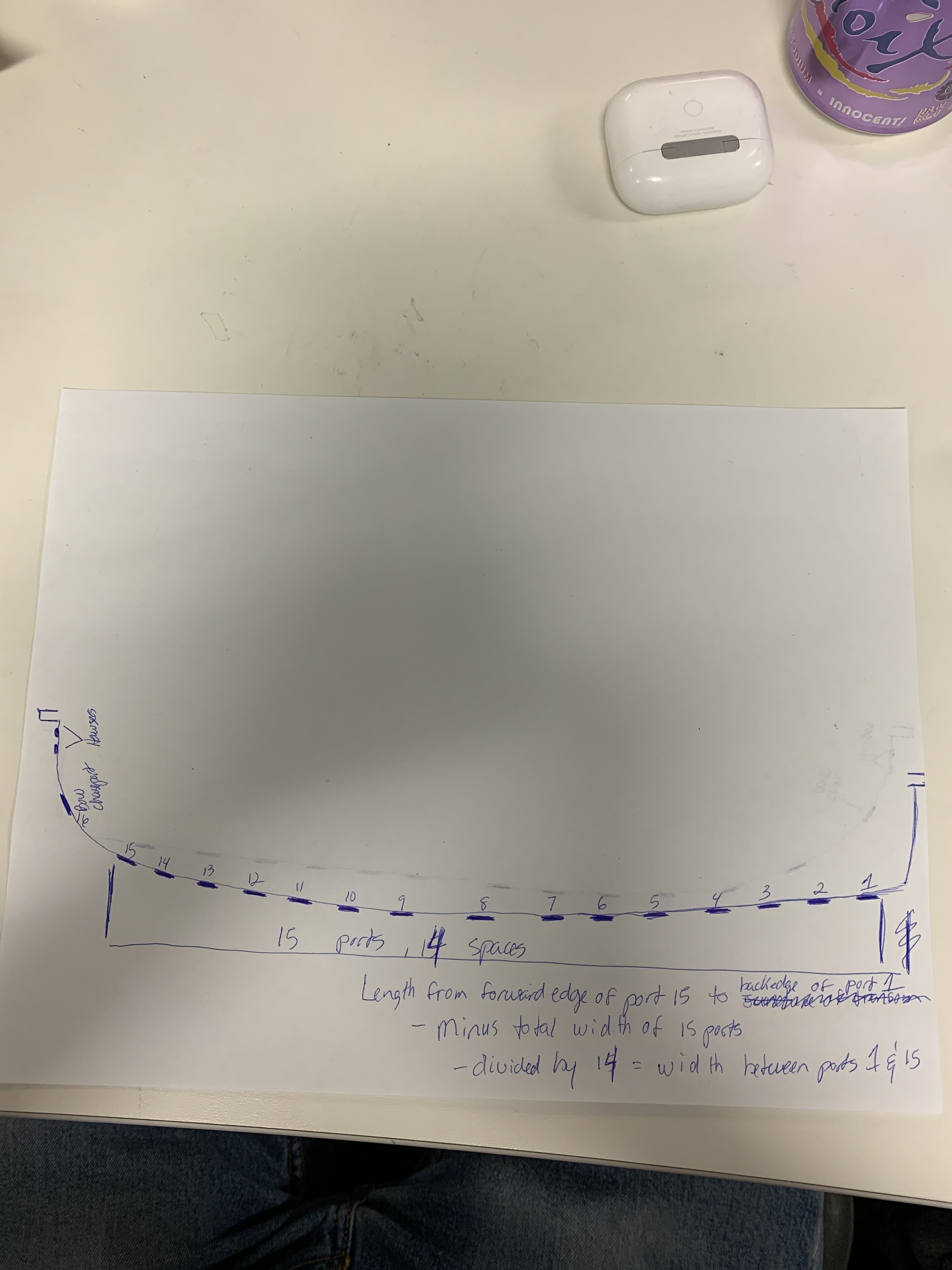
I think you measure along the outside of the hull. As you say, establish the position of port #’s 2 and 16, and then calculate even spacing for the guns in-between. A straight linear measurement of the deck length is not particularly useful, here. Here is a poor drawing illustrating the calculation. Port numbering not so important, here. You get the idea:
- 452 replies
-
- 2
-
-
- soleil royal
- Heller
- (and 1 more)
-
It’s a very small detail, Eric, but in your schematic of the proposed forward bulwark, where you show the lowered placement of the three round f’ocsle ports, I will make the following suggestion: Even though the open space will be negligible, you should not fill the gap between the top third of the round port and the underside of the caprail.
- 452 replies
-
- 1
-
-
- soleil royal
- Heller
- (and 1 more)
-
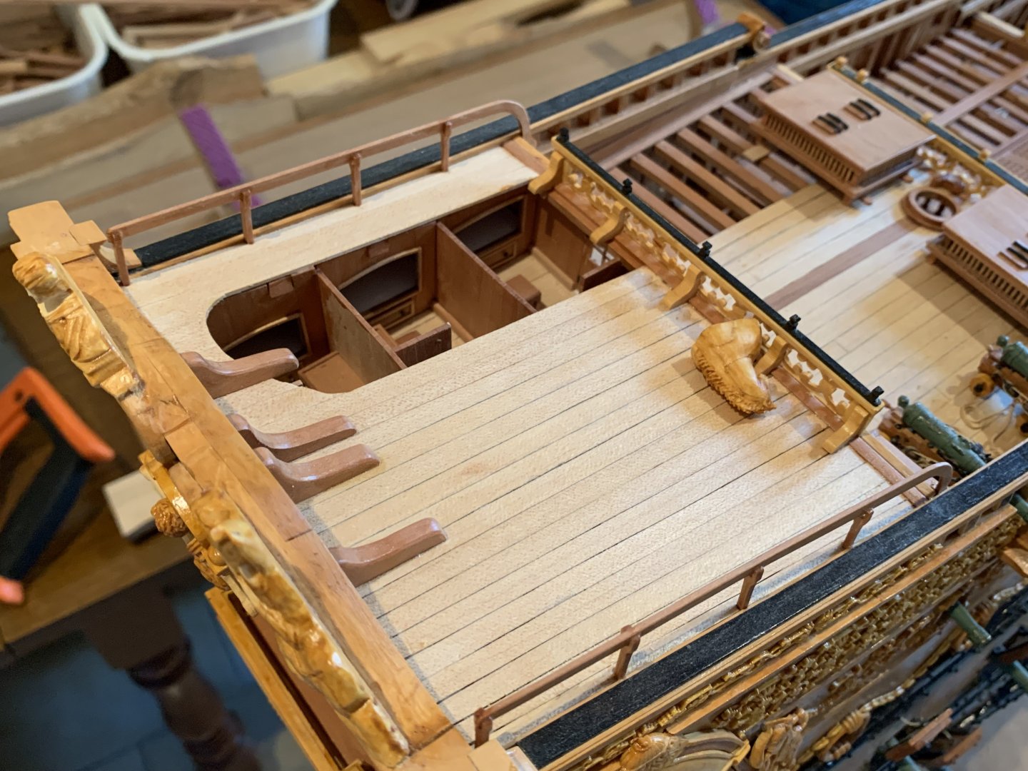
My only real issue with pronounced pitch on the poop royal deck is that this is one deck that makes sense for the open chicken coops to reside on. However, you could always stilt the legs of the coops so that they are on the level.
- 452 replies
-
- 1
-
-
- soleil royal
- Heller
- (and 1 more)
-
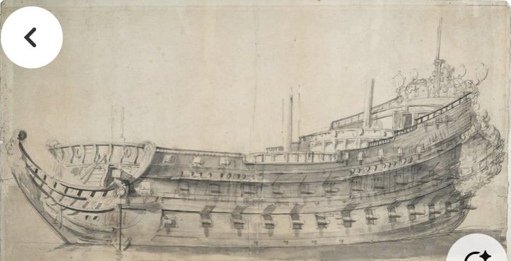
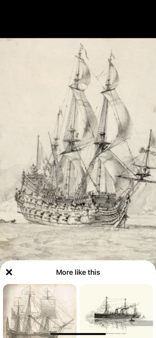
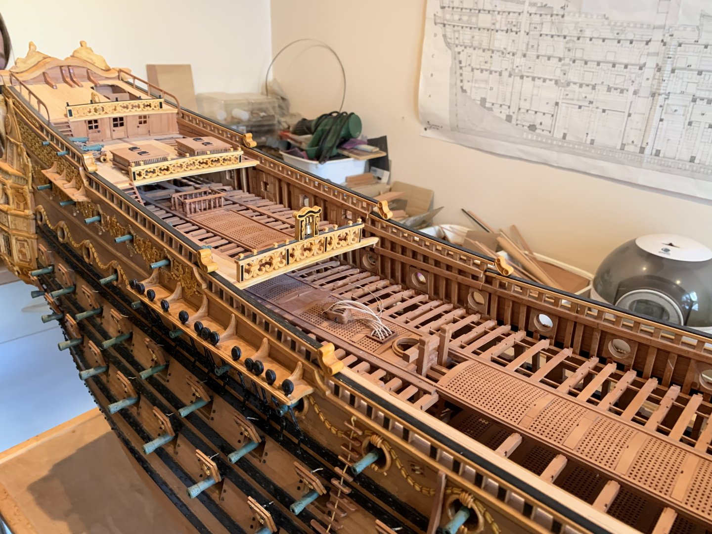
Generally speaking, Eric, your rise over run looks almost about right to me; maybe a little extreme though. I’m afraid this won’t be terribly scientific, on my part, but I would be inclined to nudge the termination points of the pair of lower main wales, down another 1/8”+. That way, you’ll have a better connection to the upper transom moulding that we discussed, above the stern chase ports. Honestly, I don’t think you were too far off on your previous iteration: As for the poop deck, which is carrying guns, it would not have any kind of pronounced forward pitch. The poop royal deck, though, may have had some pitch simply to increase headroom in these birthing cabins. Is that what is happening on the poop decks of these Dutch two-deckers: Hard to say, but it seems so. Or, what about this Dutch-built Frenchie, Le Neptune: Here’s a Puget drawing of a third-rate: I’m on the fence on this one, although Michel Saunier seems to have made a definitive choice on this question: photos, courtesy of Marc Yeu.


- 452 replies
-
- 4
-
-
- soleil royal
- Heller
- (and 1 more)
-
Michael, thank you so much for the kind words!
-
Alright, so I was wrong about SR 1693; her length between perpendiculars was actually 170’ FF. This amounts to an increase of 5.5’ FF, or 5.863’ Imperial.

-
SR1’s keel length was 142 French feet, which is longer than the English and Imperial foot by 1.066. That is one factor. The other is that the Heller Kit is based on the dimensions of SR 1693, which I don’t remember exactly, but I think measured 172 French feet between perpendiculars - which is the measurement from the forward most face of the stem to the furthest aft rake of the stern post.
-
Because this plastic is so thick, my preferred method for cutting openings is to neatly scribe the opening; drill a series of tightly spaced holes within that opening, using a Dremel; cut through the perforations with a stiff box knife; and then square to my lines with files.
- 452 replies
-
- 3
-
-
- soleil royal
- Heller
- (and 1 more)
-
It’s super tedious, Eric, but you’ll want to thoroughly level any wales or ornamental footprints, otherwise there is a good chance they will telegraph through your thin styrene planking.
- 452 replies
-
- 1
-
-
- soleil royal
- Heller
- (and 1 more)
-
Really beautiful execution!
-
Hello Wefalck, With the busyness of the holidays, I somehow missed this update to the log. I’m just seeing this now. My apologies for such a late reply. I hear what you are saying about the fretwork panels, and ordinarily, I would agree with you. The problem, I have found is with the material, itself. Fretting out styrene - especially such small parts - is very difficult to do without introducing un-intended deformities to the perimeter of the parts; the material is just too flexy. This is why, I like to leave it in-sheet while I fret it. That way, I am much less likely to break these fragile pieces, as I did with the trailbord, when I first tried doing this the more conventional way. For assembly of these breast rails, I will place the central panels first - the belfry and the name plaque for the QD - which are bracketed by their stanchions to either side, and then I will build the breastworks out from the center. I have already glued the peripheral breast panels to their corresponding outboard stanchions. This way, I can bevel the stanchion knee bases to the port/strbrd camber of the deck, while ensuring that the top edges of each panel align in a fair arc. The beauty of this approach is that I will have firmly established stanchion head locations to accurately pierce the breast work caprails. Or, at least, that is my theory 😜 Happy New Year to All! Best, M
- 2,699 replies
-
- 5
-
-
- heller
- soleil royal
- (and 9 more)
-
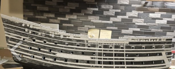
Heller’s SR looks amazing in sheer, but you just can’t focus too much on her underwater shapes. When you minimize the visibility of the lower hull, you vastly improve the credibility of the kit as a scale model.
- 452 replies
-
- 1
-
-
- soleil royal
- Heller
- (and 1 more)
-
The other issue with a lower hull build-out is that the entire midship to bow, along the maximum breadth is just all wrong.
-
Personally, Eric, I would not even consider building out, or expanding the lower hull. It could be done, but you would need to figure out the rising line of the floors and make pattern guides that faired into the maximum breadth line. The number of difficulties in doing this without CAD are numerous, and getting one small thing wrong, or working from an erroneous assumption could compromise the whole project. Not worth it, IMO. Conversely, it is not too difficult to place the un-cut hull into a waterline sea. As for the QG entry doors, there would definitely have been an actual door there, opening inboard. Seaways can get awful rough, and a ship’s capacity to pump out water would be quickly overwhelmed, if she were taking water in through these large openings.
- 452 replies
-
- 1
-
-
- soleil royal
- Heller
- (and 1 more)