drobinson02199
-
Posts
1,079 -
Joined
-
Last visited
Content Type
Profiles
Forums
Gallery
Events
Everything posted by drobinson02199
-
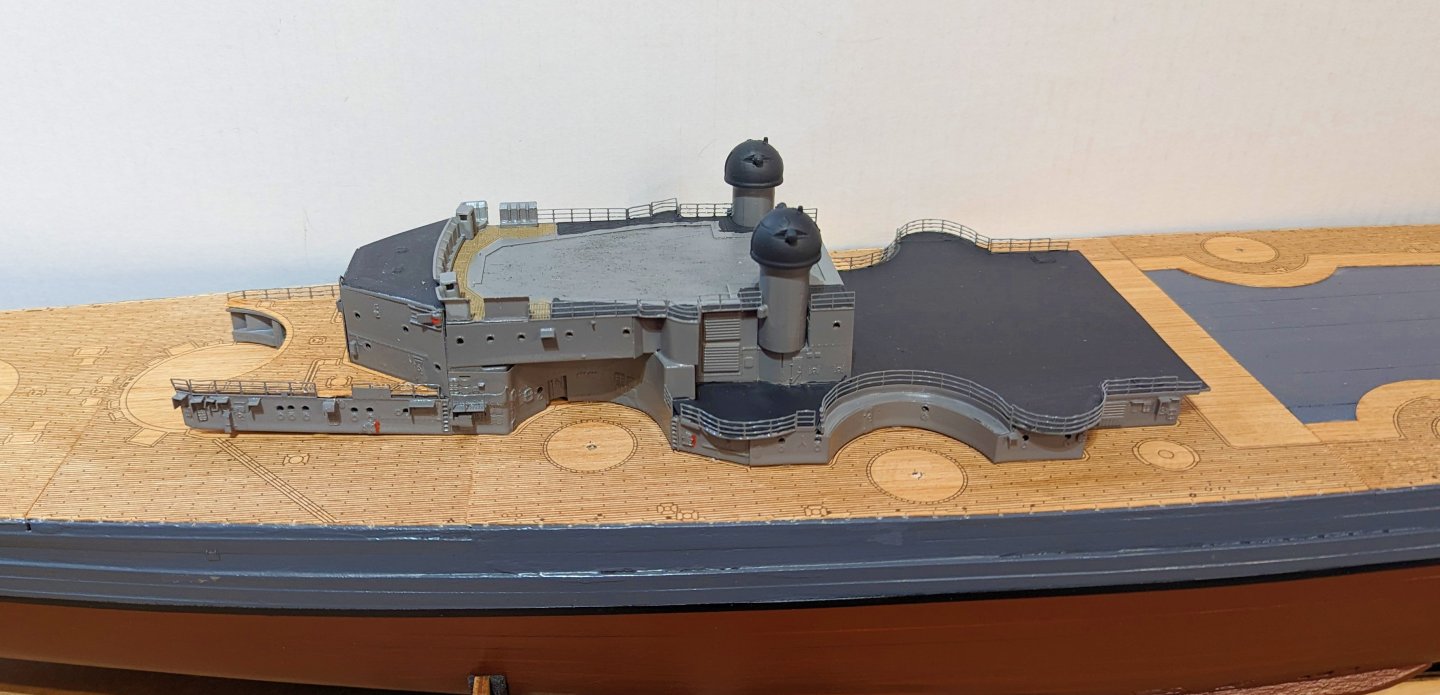
 Next set of levels mounted. I'm into painting completed structures, so this should go up fairly quickly, and I'll keep posting progress pics as I go. Regards, David
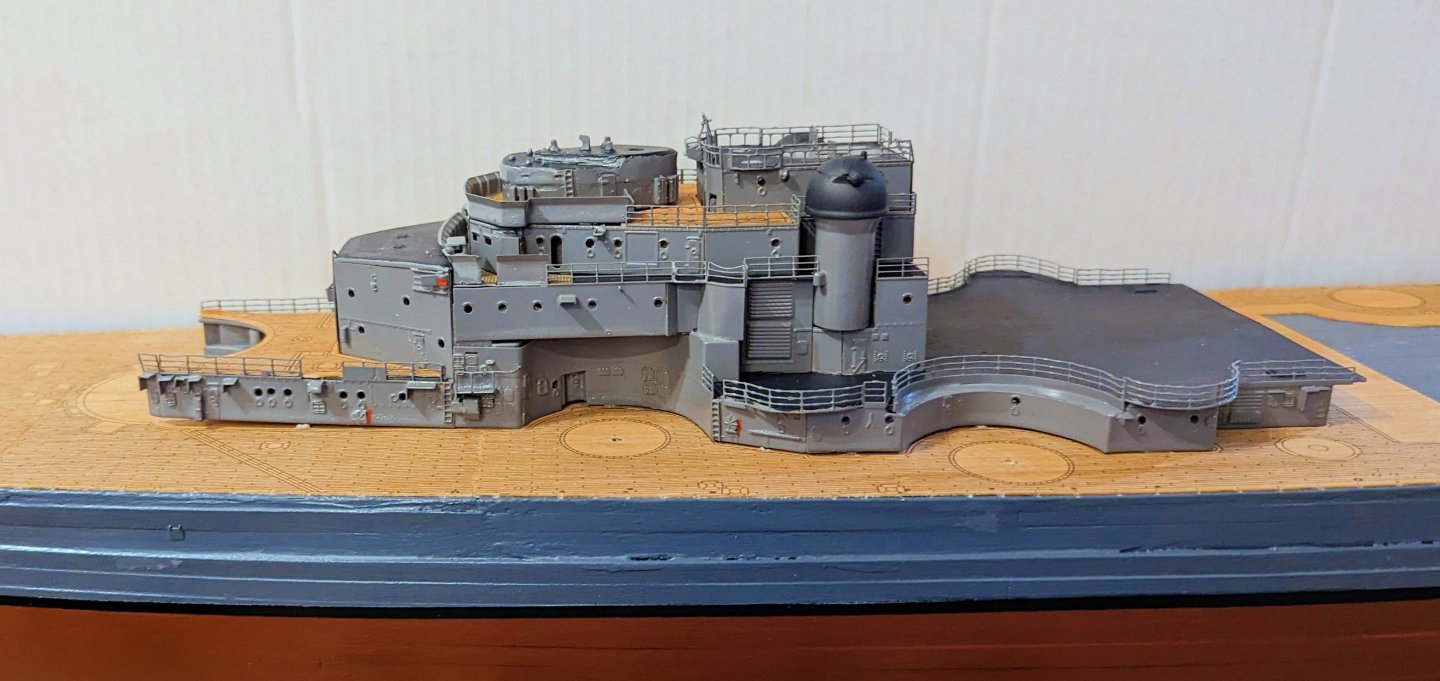
-
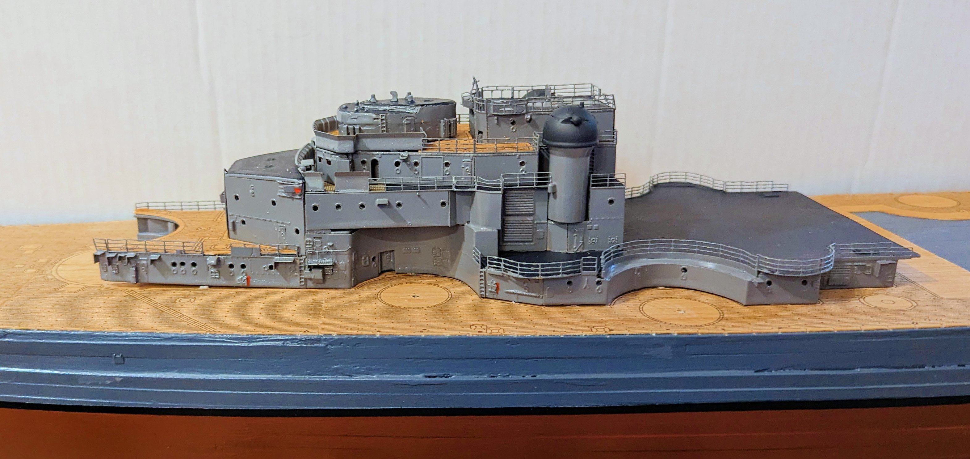
Put up my spray booth and have now started to paint and assemble the bow superstructure. First and second levels shown here, in position and glued to the ship. Regards, David

-
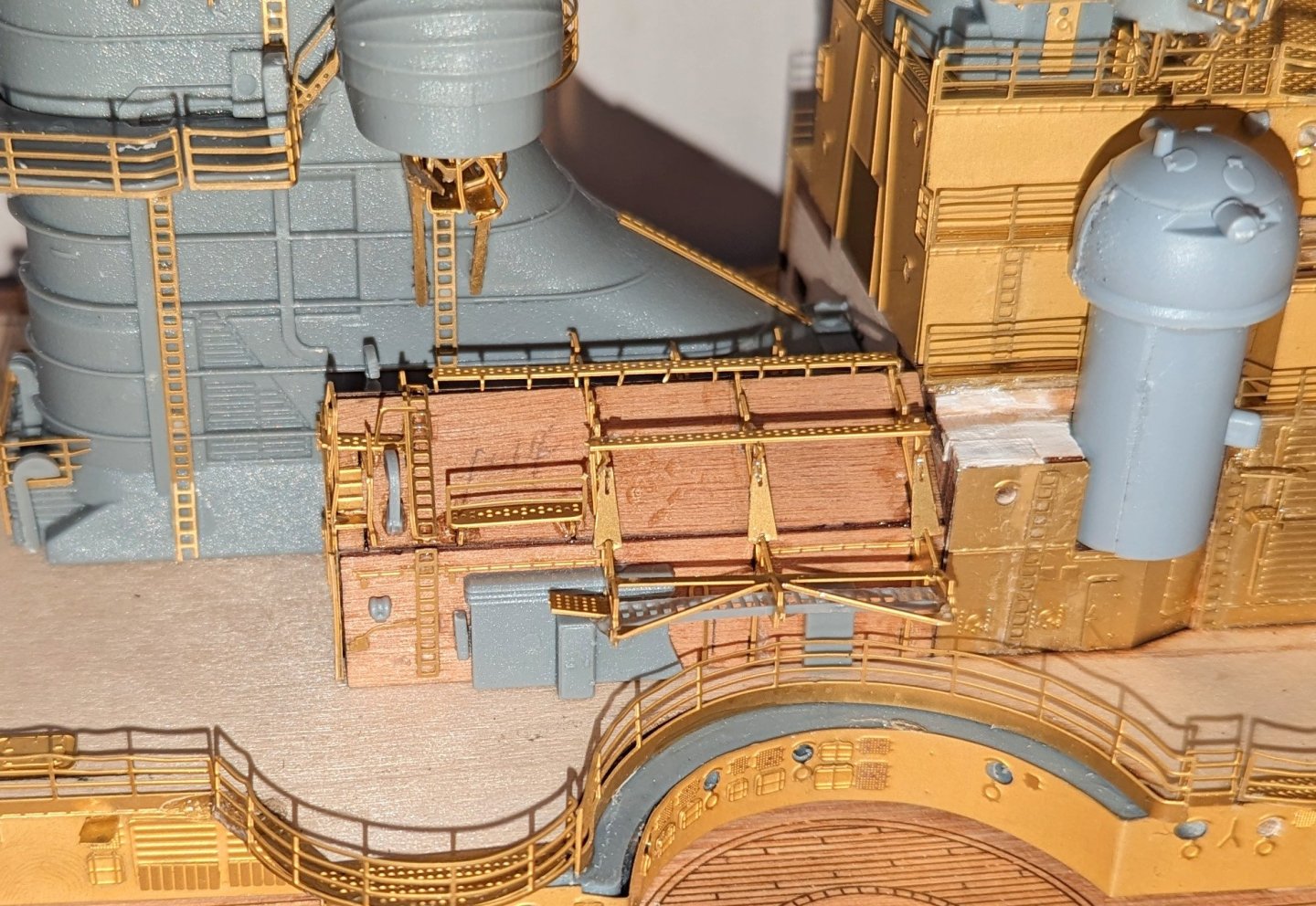
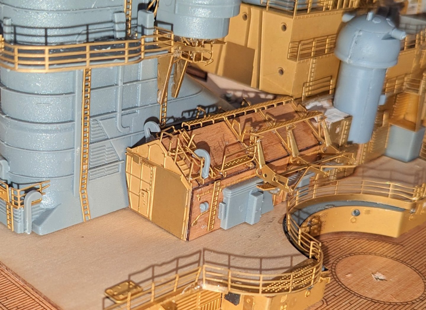
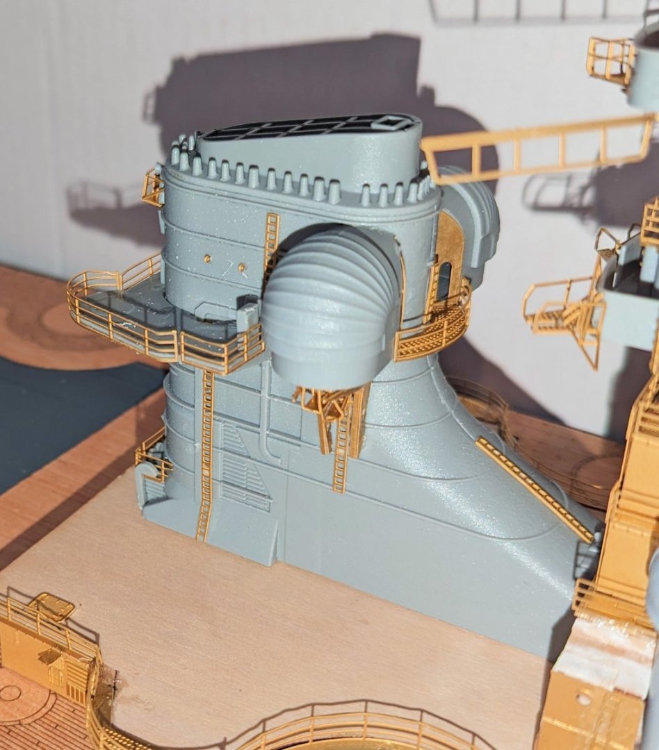
This is the starboard hangar in its position next to the funnel. An identical one goes on the port side, and I will build that now. Really nice detail here -- and of course all of this will be painted gray. A tip: there are notched slots in the roof to accept the brass pieces. I used a craft knife to widen them so they would more easily accept the fittings. Regards, David
-
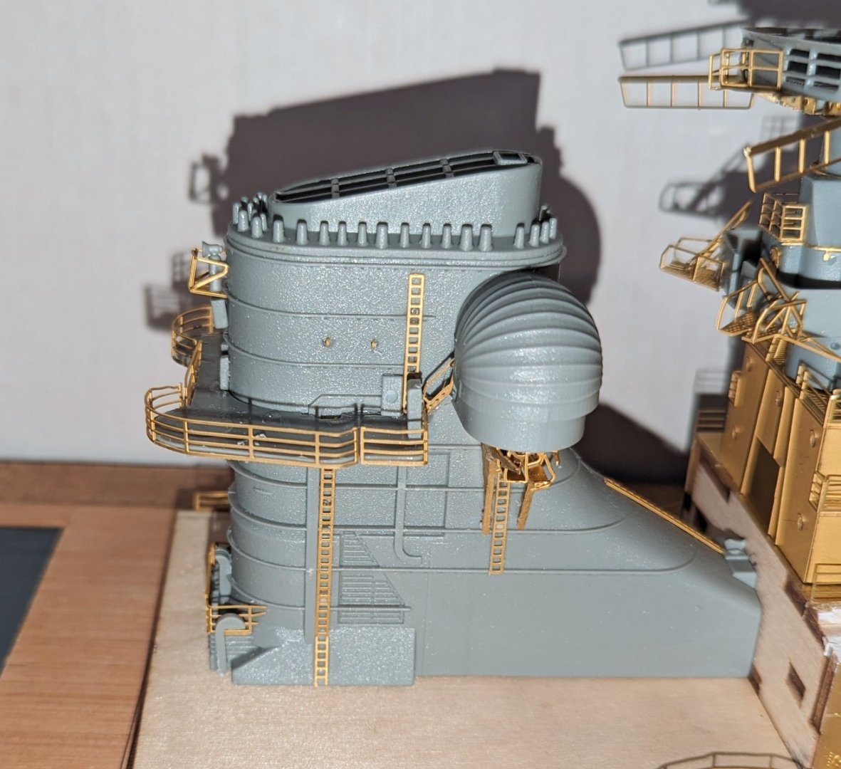
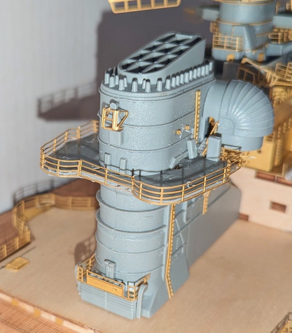
This is the funnel, in the position it will eventually hold. There are some very difficult assemblies in this, and I butchered one beyond fixing. See if you can find it. 😁 Regards, David
-
Thanks, Ian. I've found the most challenging part to be the tiny little brass and plastic pieces -- the smallest ones. I've lost a couple that slipped out of my tweezers onto the floor, where I couldn't find them, but they are so small that I have said "to hell with it, they will never be noticed" and moved on. 😁 Regards, David
-
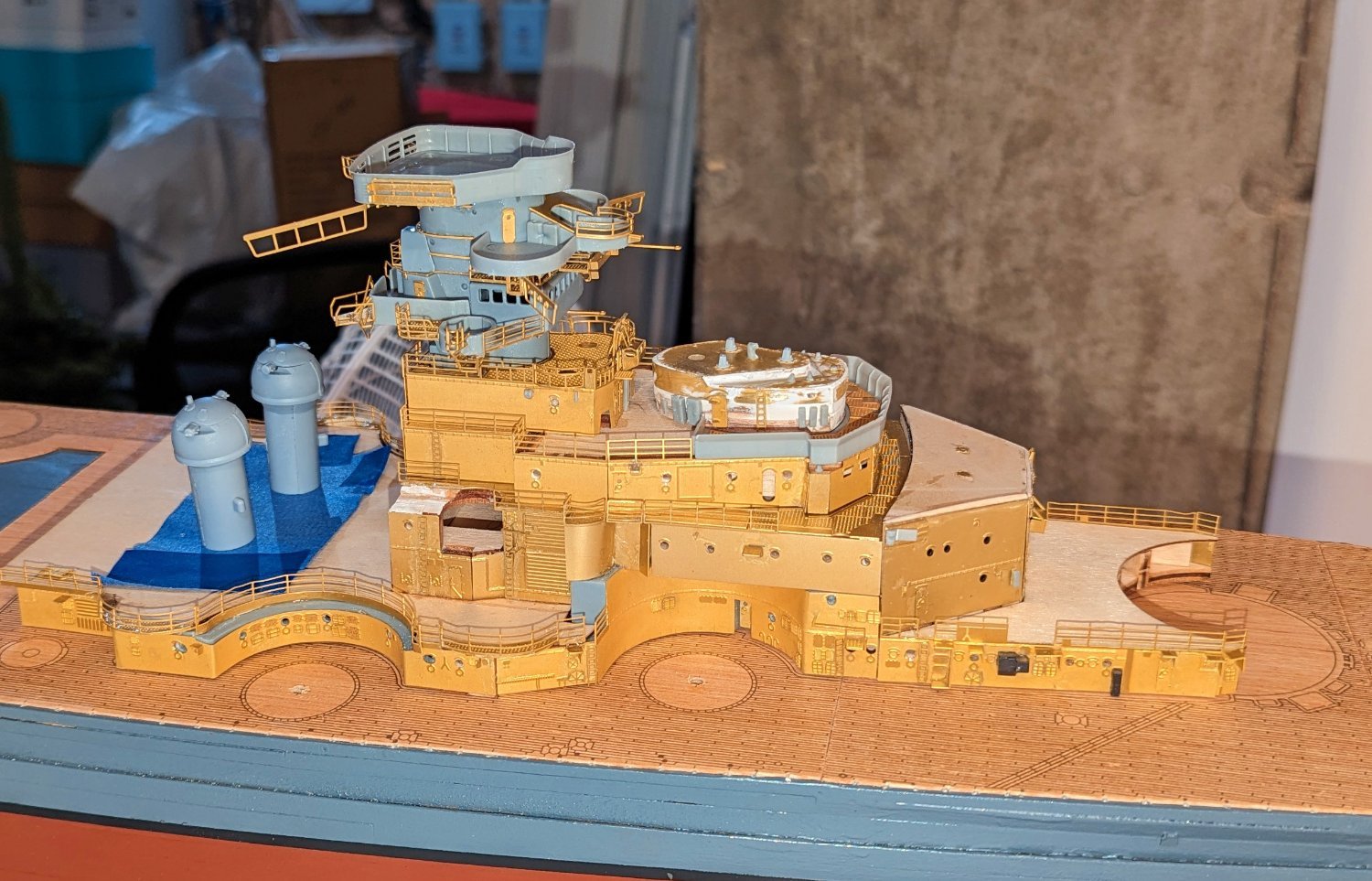
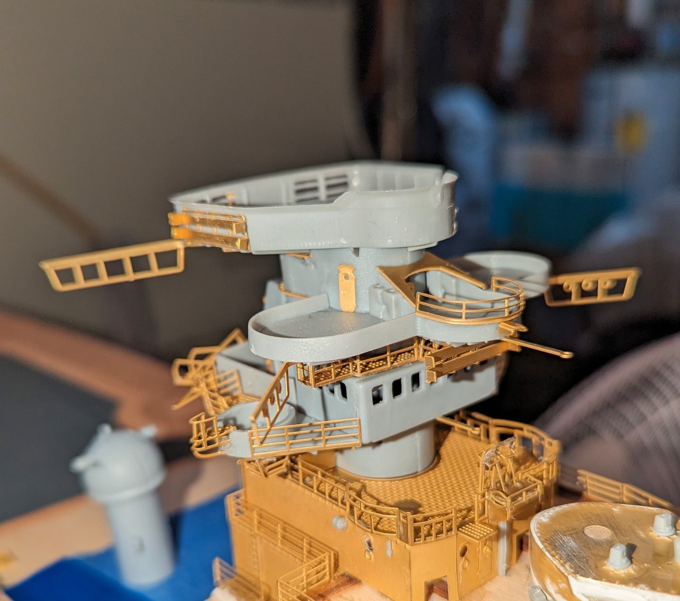
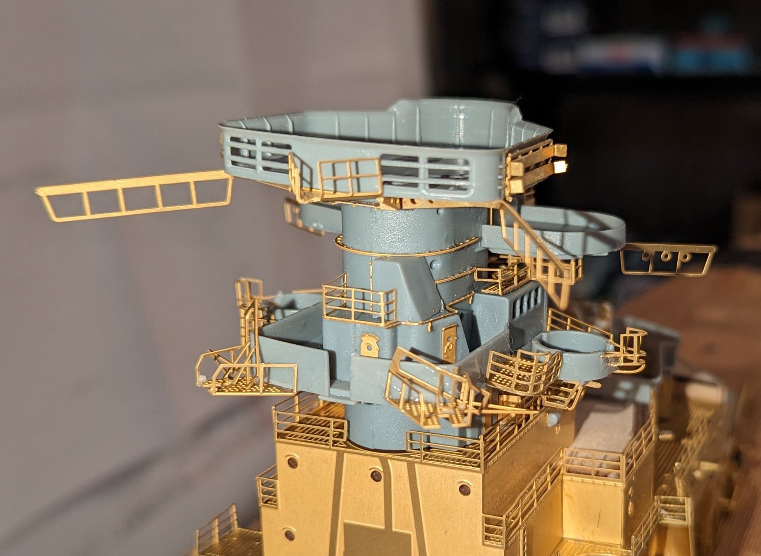
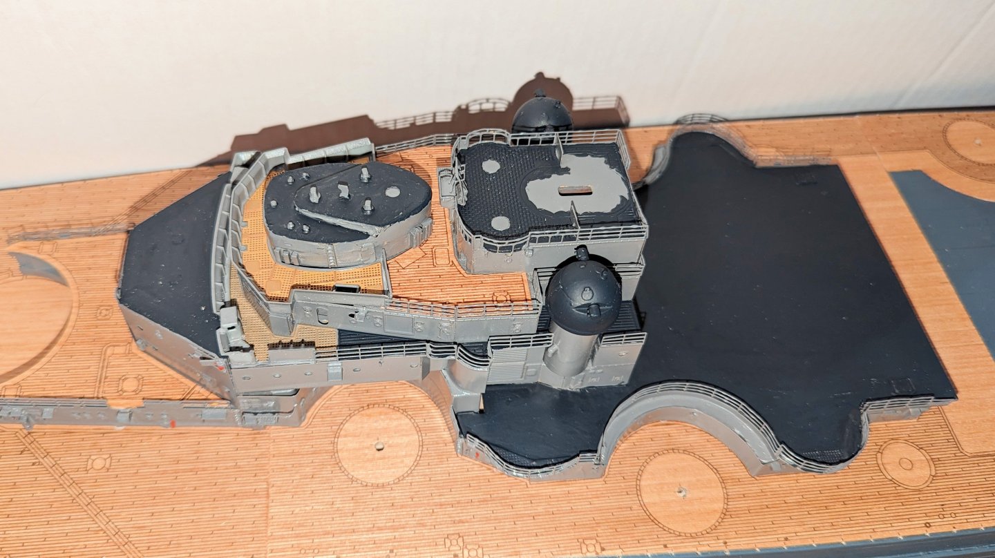
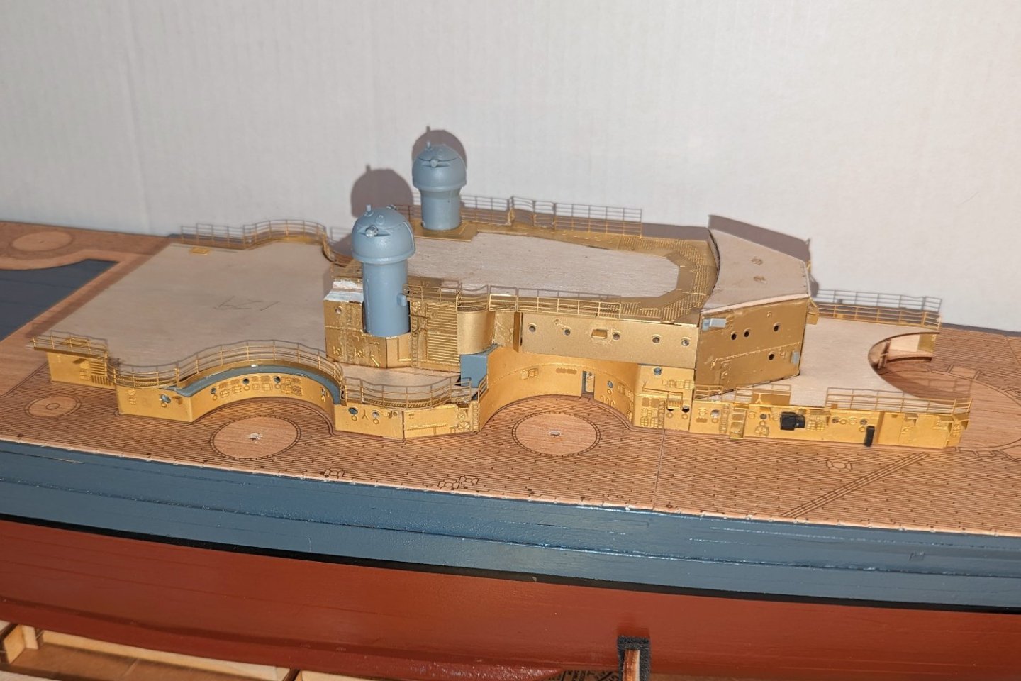
More stages of the bow superstructure. I've added some closeups showing the new detail. The turrets have been removed here and "parked" on a piece of tape. It might seem like I'm going fast, but I had held the previous stage for about 5 days waiting for some paint to arrive, and was working on this stage during that time. Regards, David


-
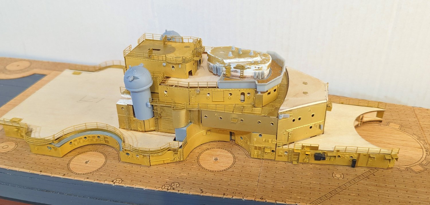
Bow structure continues to take shape -- the new layers are dry-fitted as things need to be painted in stages. The white patches on the top of the structure are putty. Regards, David

-
More work on the lower level of the bow structure. The two gun turrets are dry-fitted for now. Some of the detail pieces are fiendishly small. I've lost a couple of the really tiny ones on my workbench, but you can't really tell. Regards, David
-
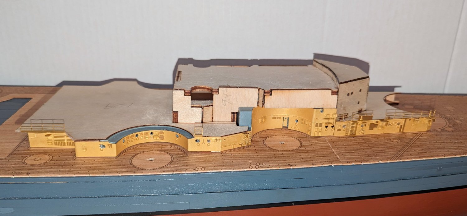
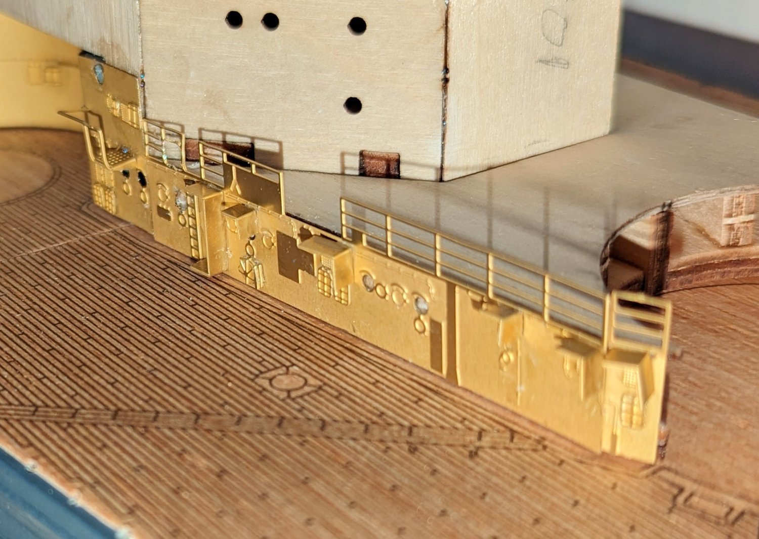
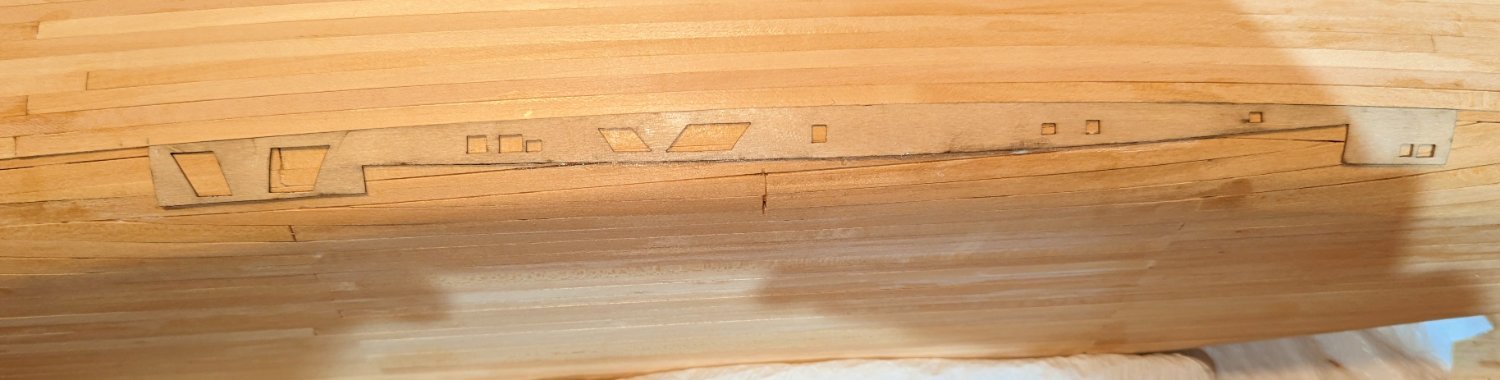
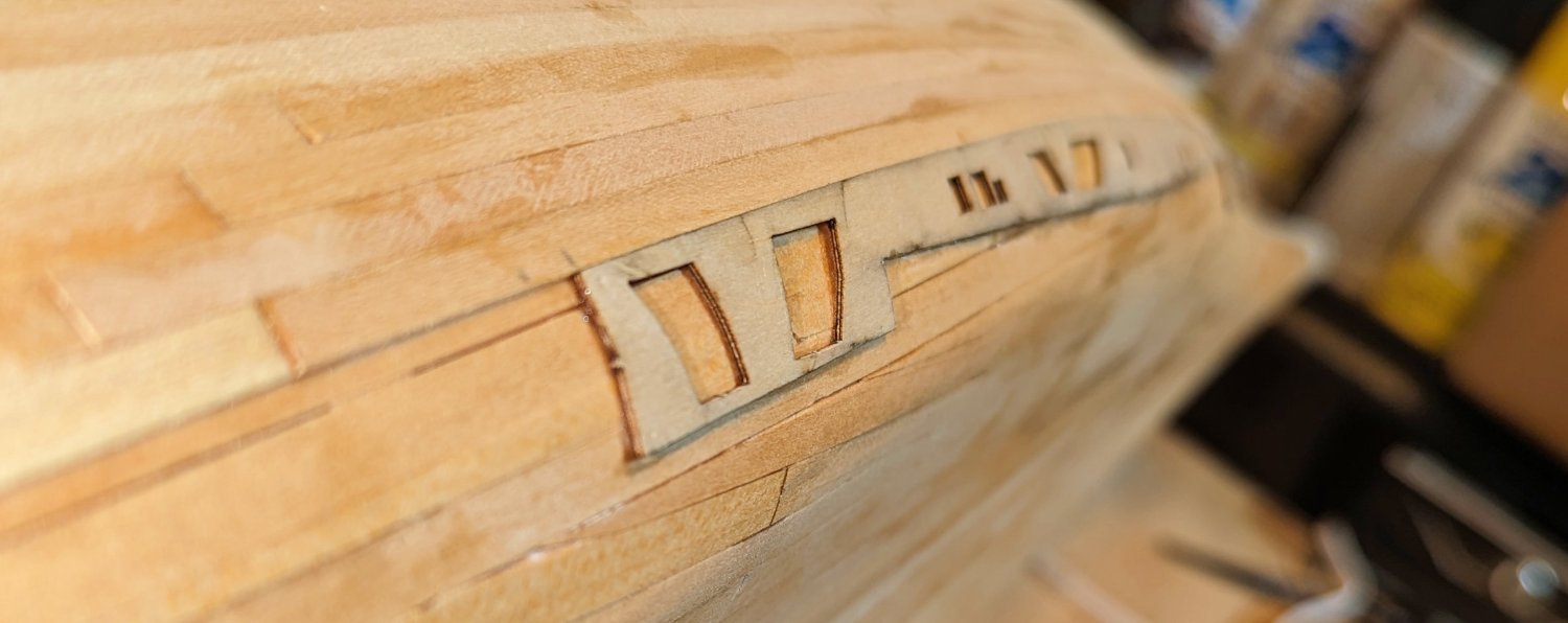
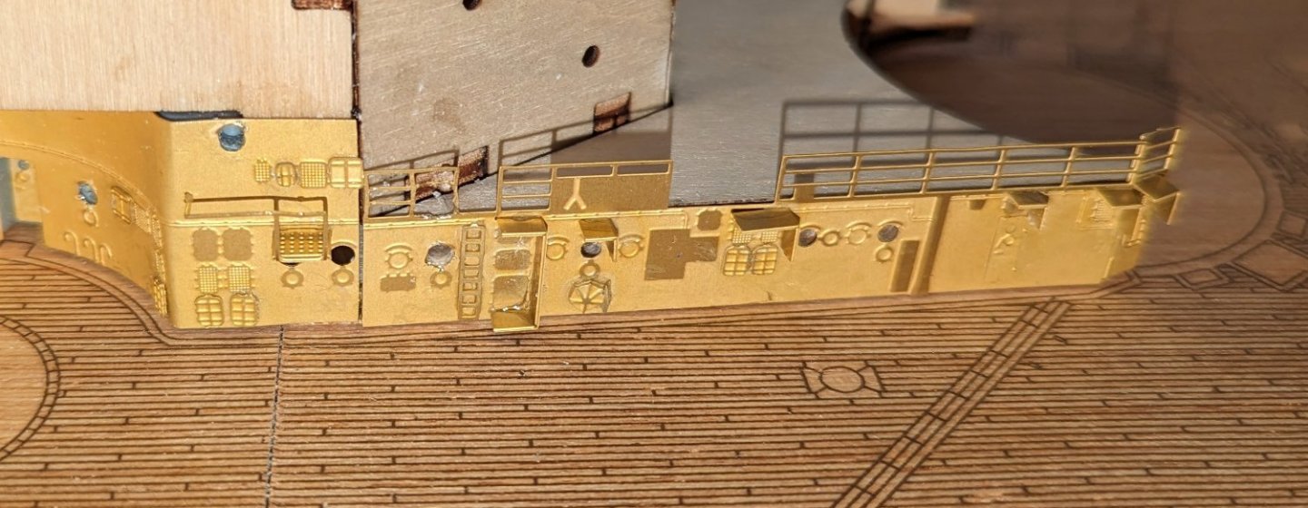
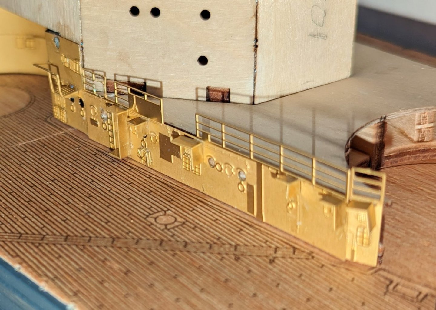
This ship shows an incredible level of detail, achieved by using brass etched sections on the sides that will ultimately be spray painted gray. This is the first level of the starboard side. There is detail etched into the surface of the base plates, and then you add very tiny pieces on top to create additional raised detail. Regards, David

-
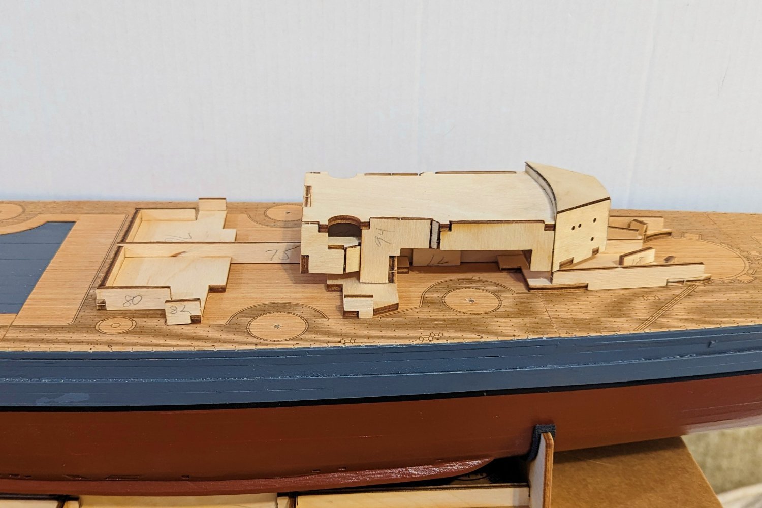
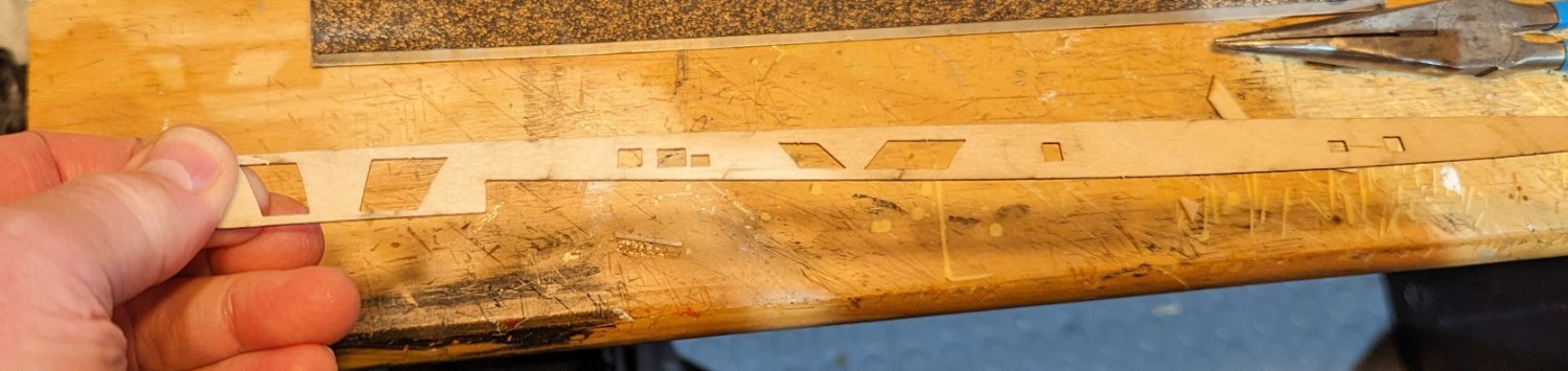
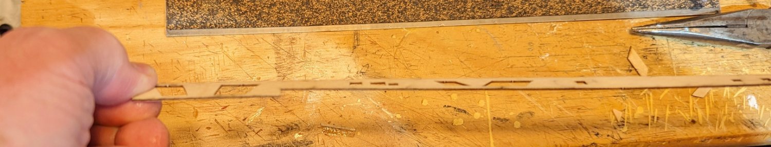
Something I forgot to mention for any of you who might be using this build log as a reference for your own Bismarck build: The base frame for the structure in the picture above is initially built in two sections -- front and rear. Those are then joined by stringers on the sides of the beams that run fore and aft -- you can see the beam numbered 75 above, but the join is hidden now. You use the deck pattern to get the spacing of the fore and aft sections right before joining them with the stringers. But the picture in the manual is confusing -- it didn't seem right to me when I looked at my model. It was only after really close inspection and comparison (including using a magnifying glass on the picture) that I realized that the actual pattern I have is different -- slightly -- from the one pictured in the manual. So I then used common sense to do the alignment. Point of this is that you could make a really serious mistake if you just look at the picture and align the way it shows. Regards, David
-
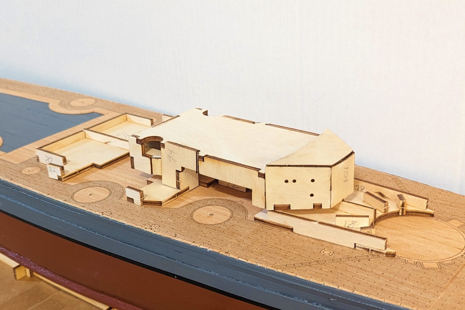
Intermediate progress on the first structure. In position but not glued to the deck. Regards, David


-
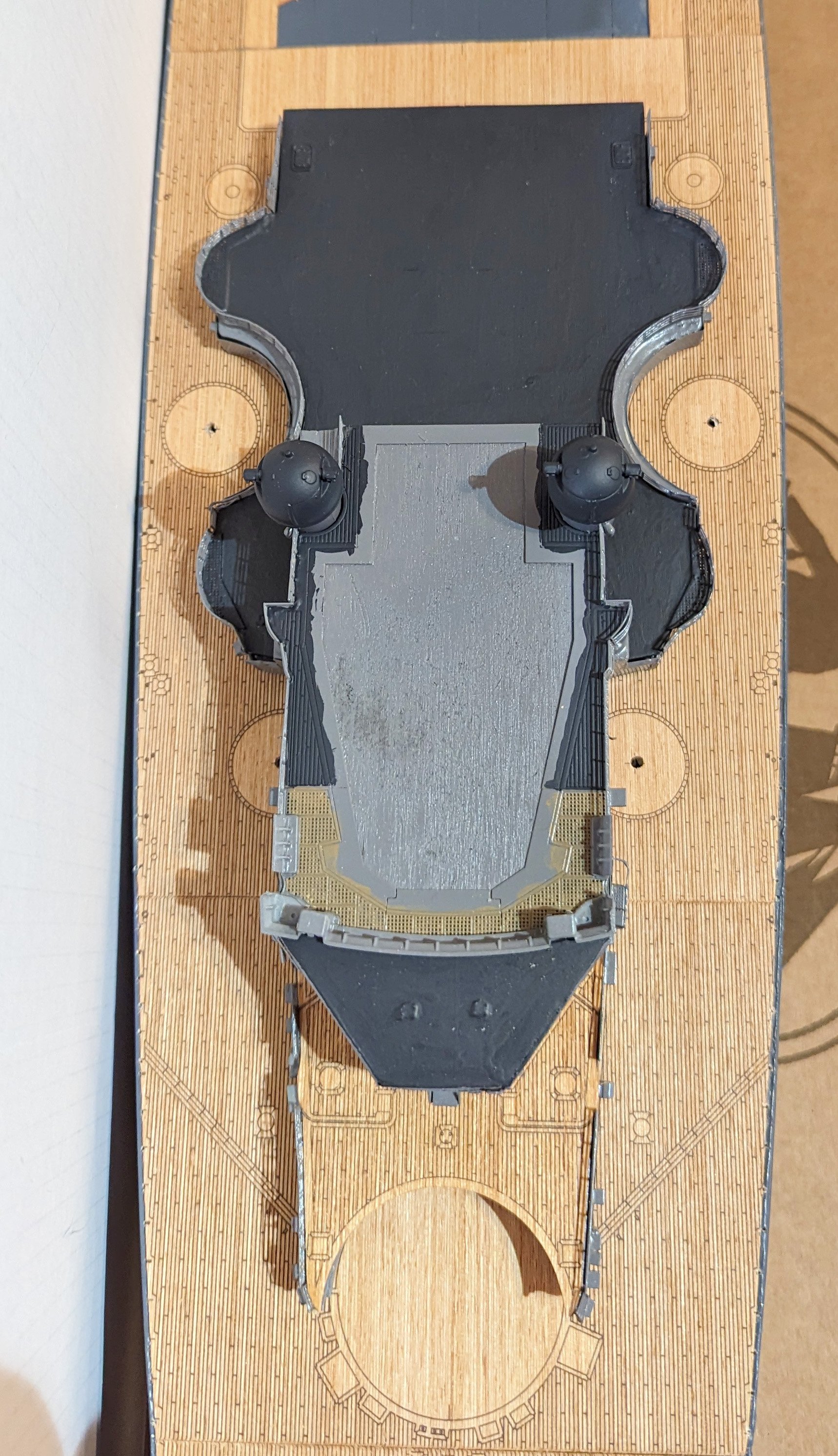
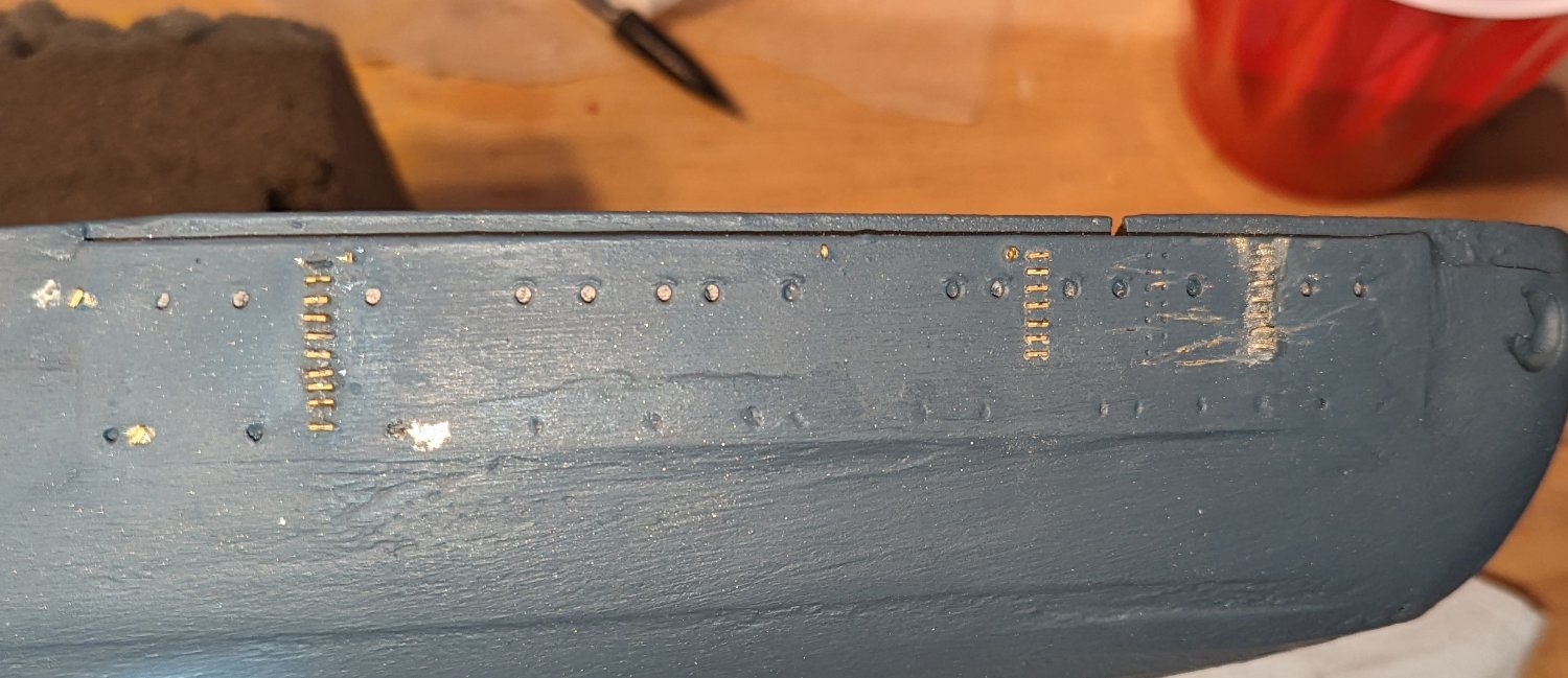
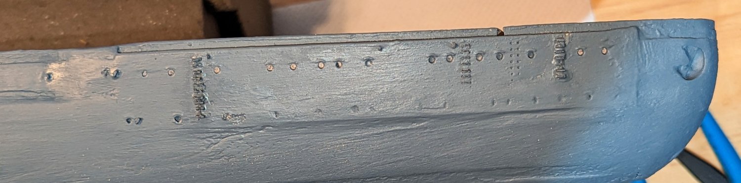
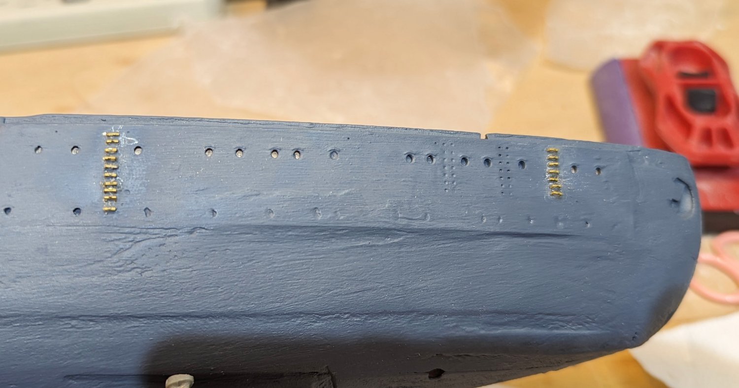
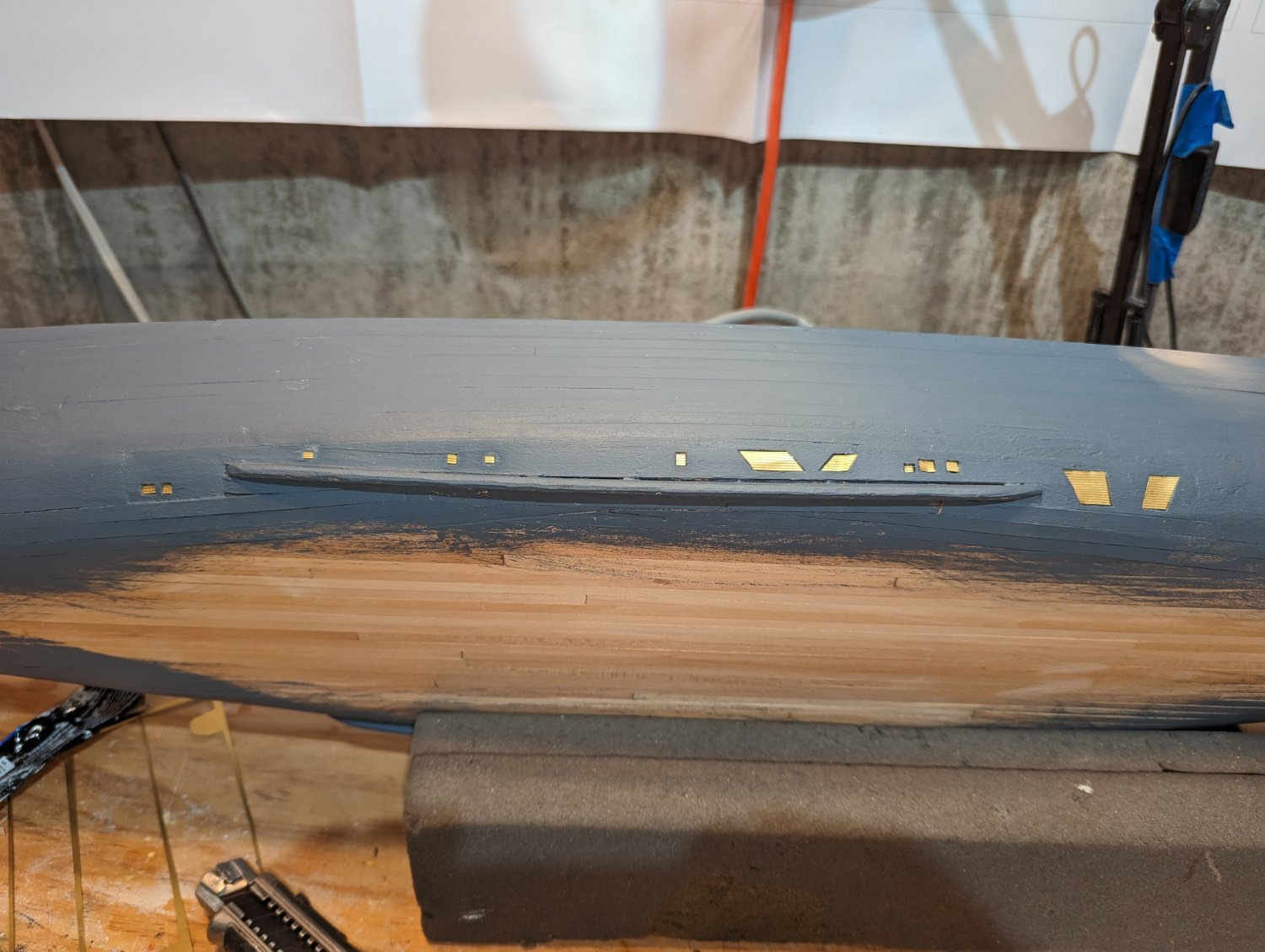
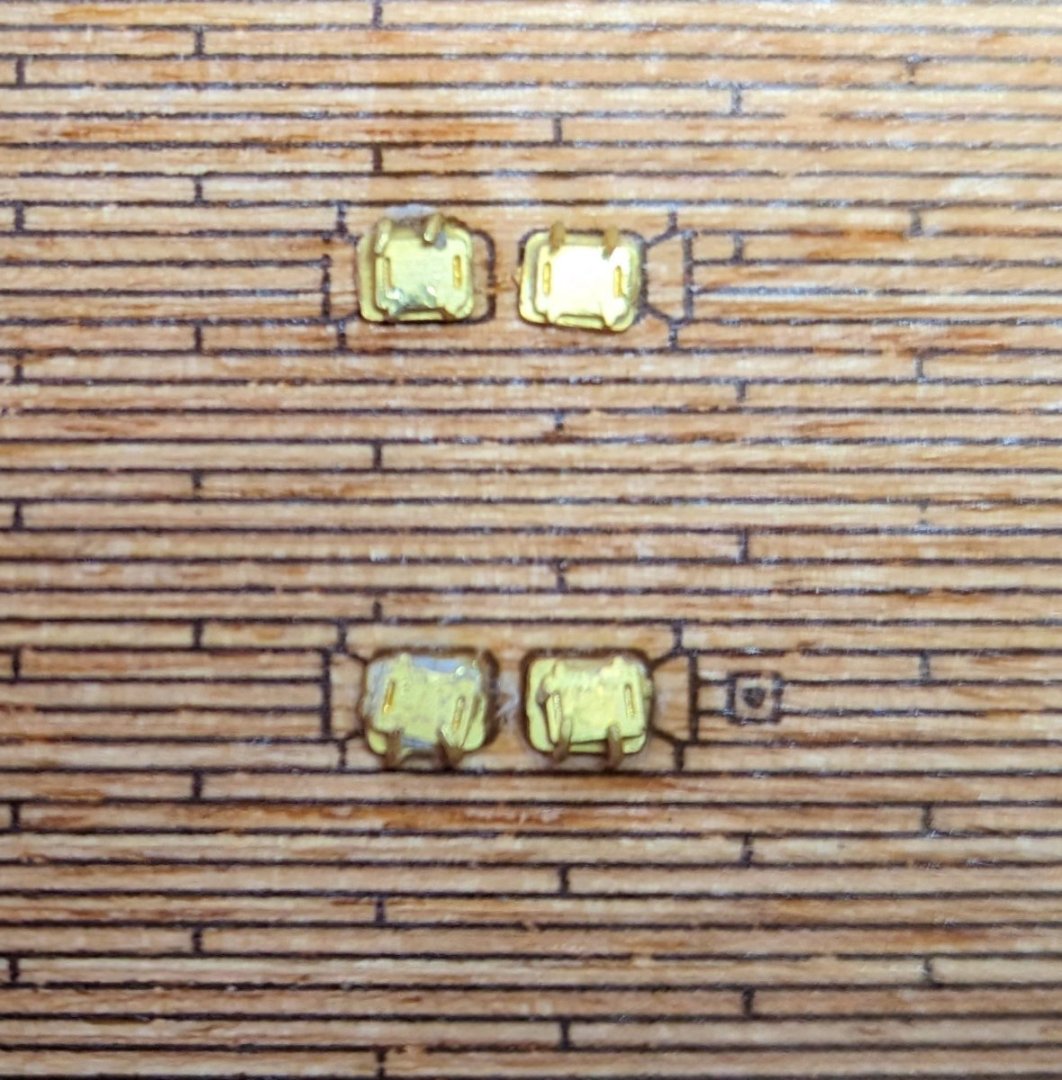
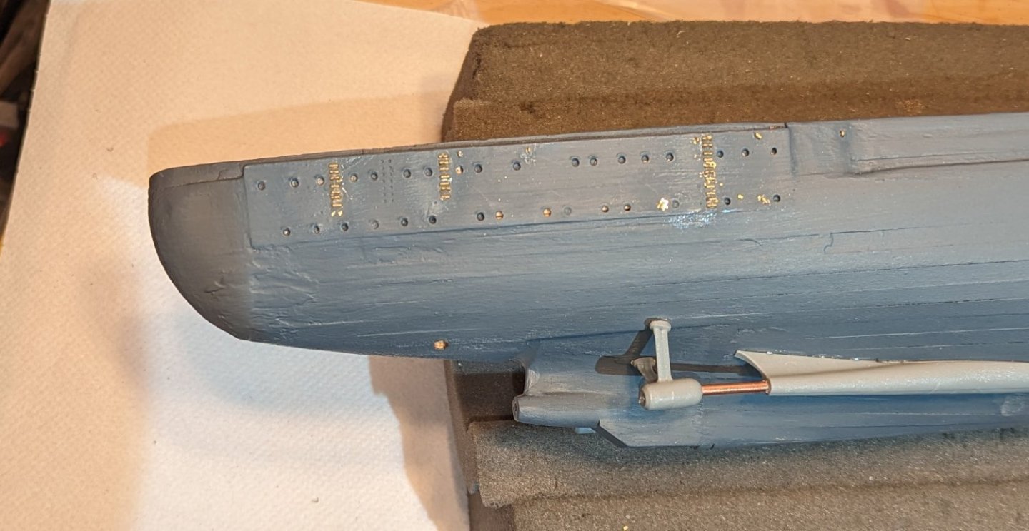
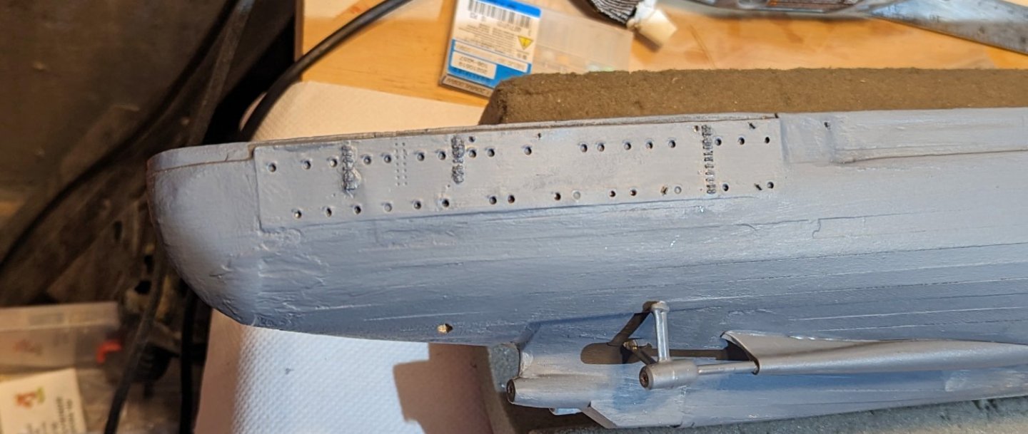
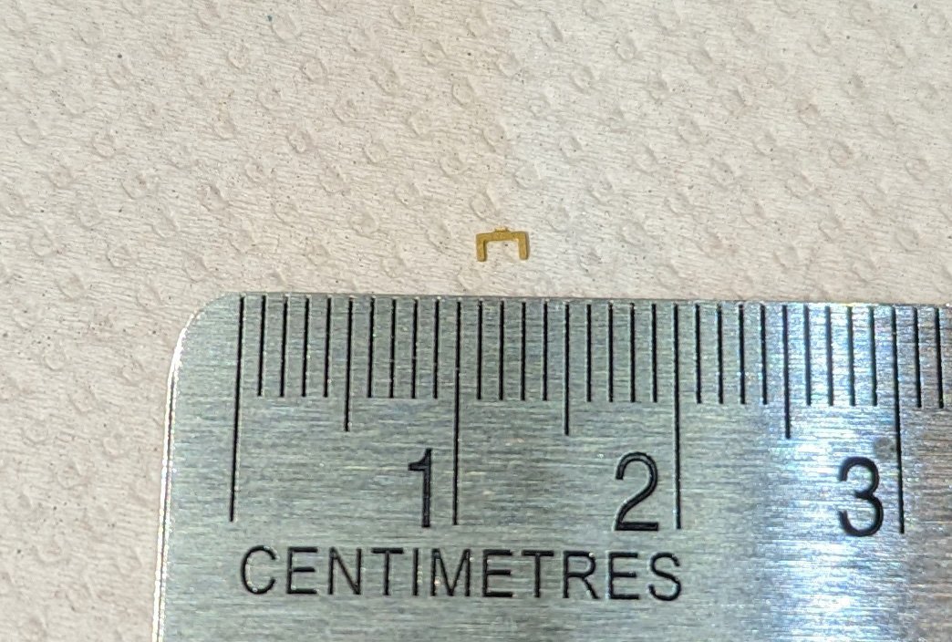
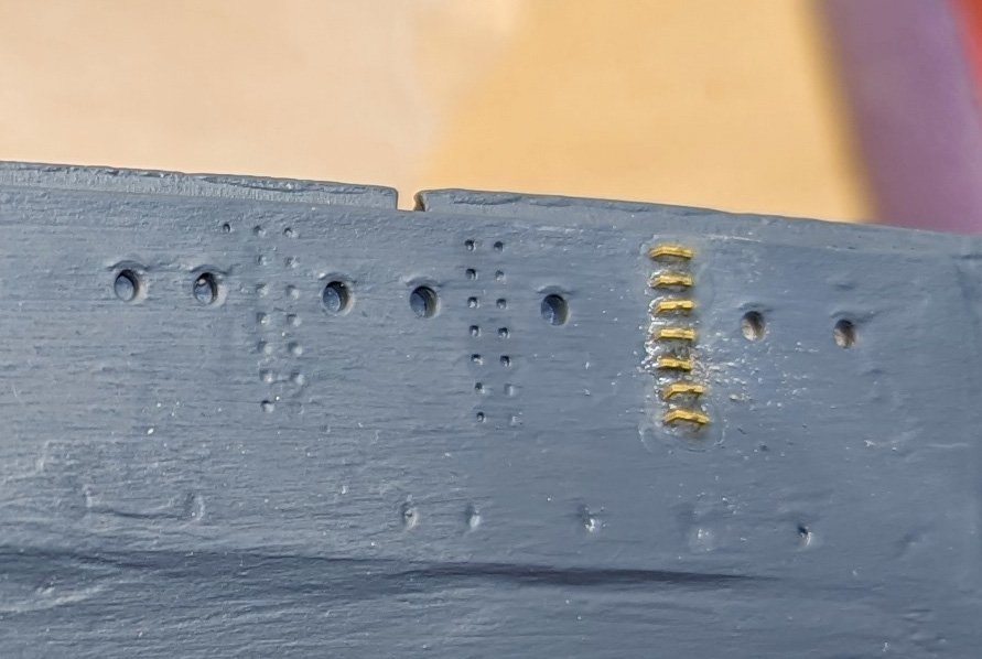
Tiny hatches assembled and mounted on the stern. These are painted over in the pictures that follow. Then areas painted in "German Gray". Everything from here on is superstructure. Regards, David
-
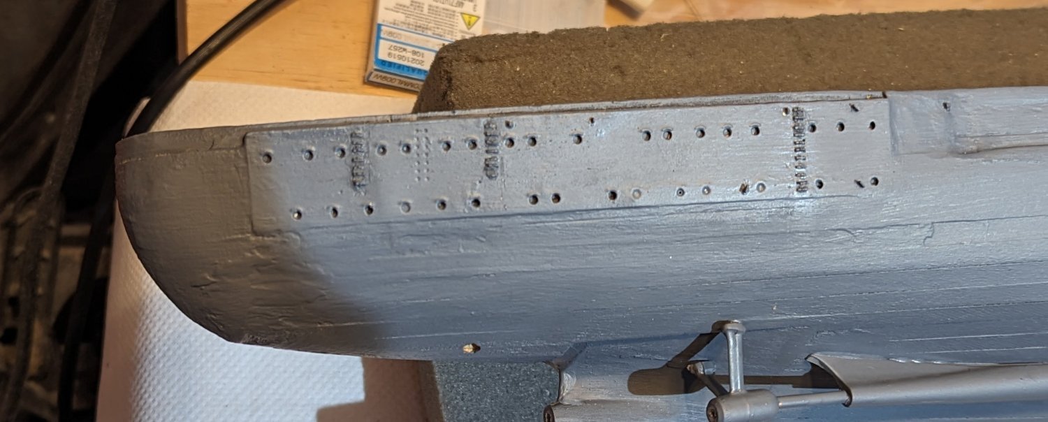
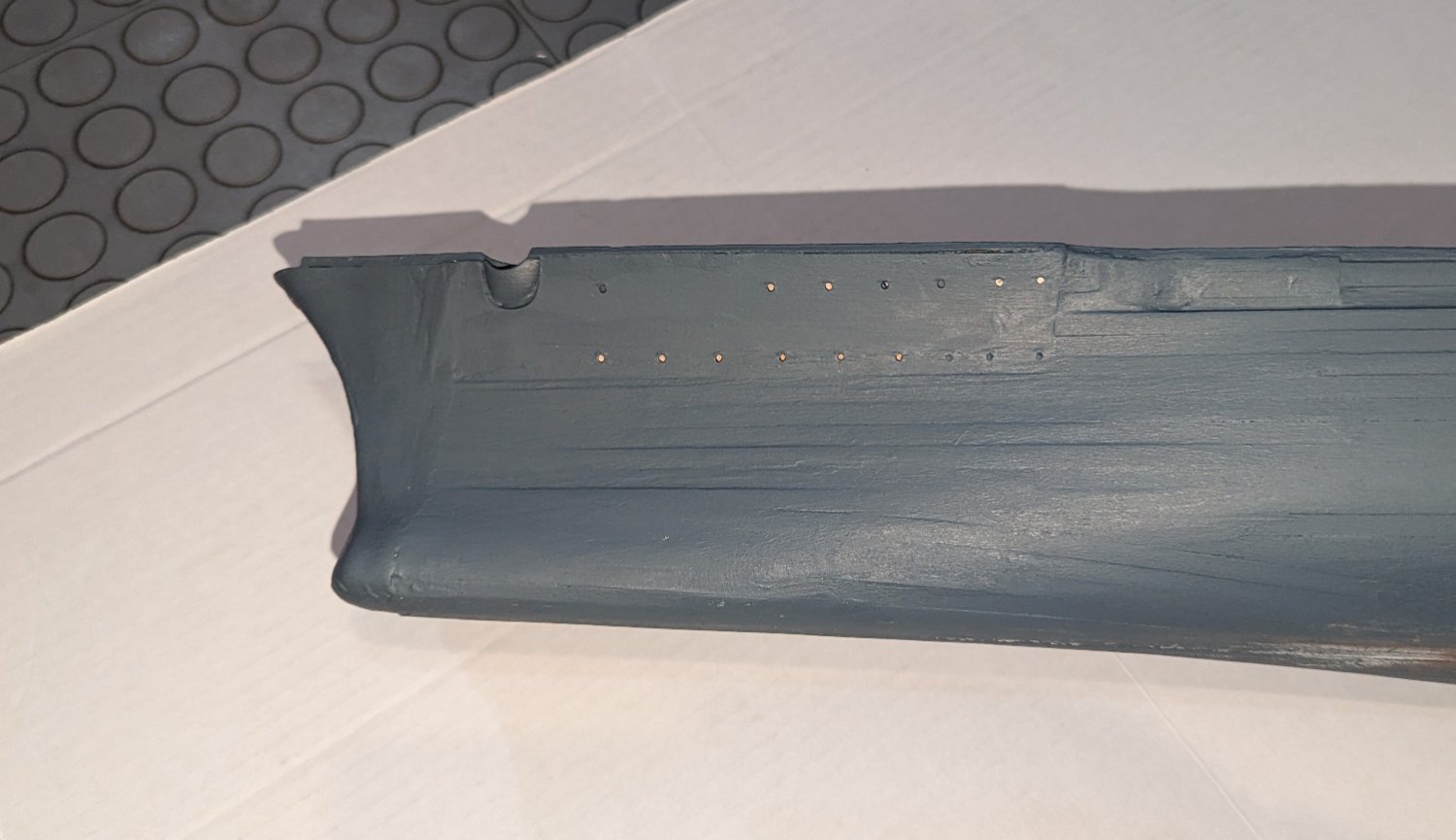
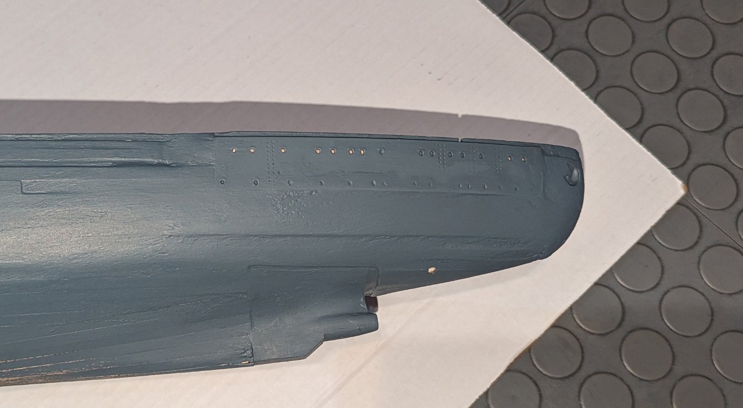
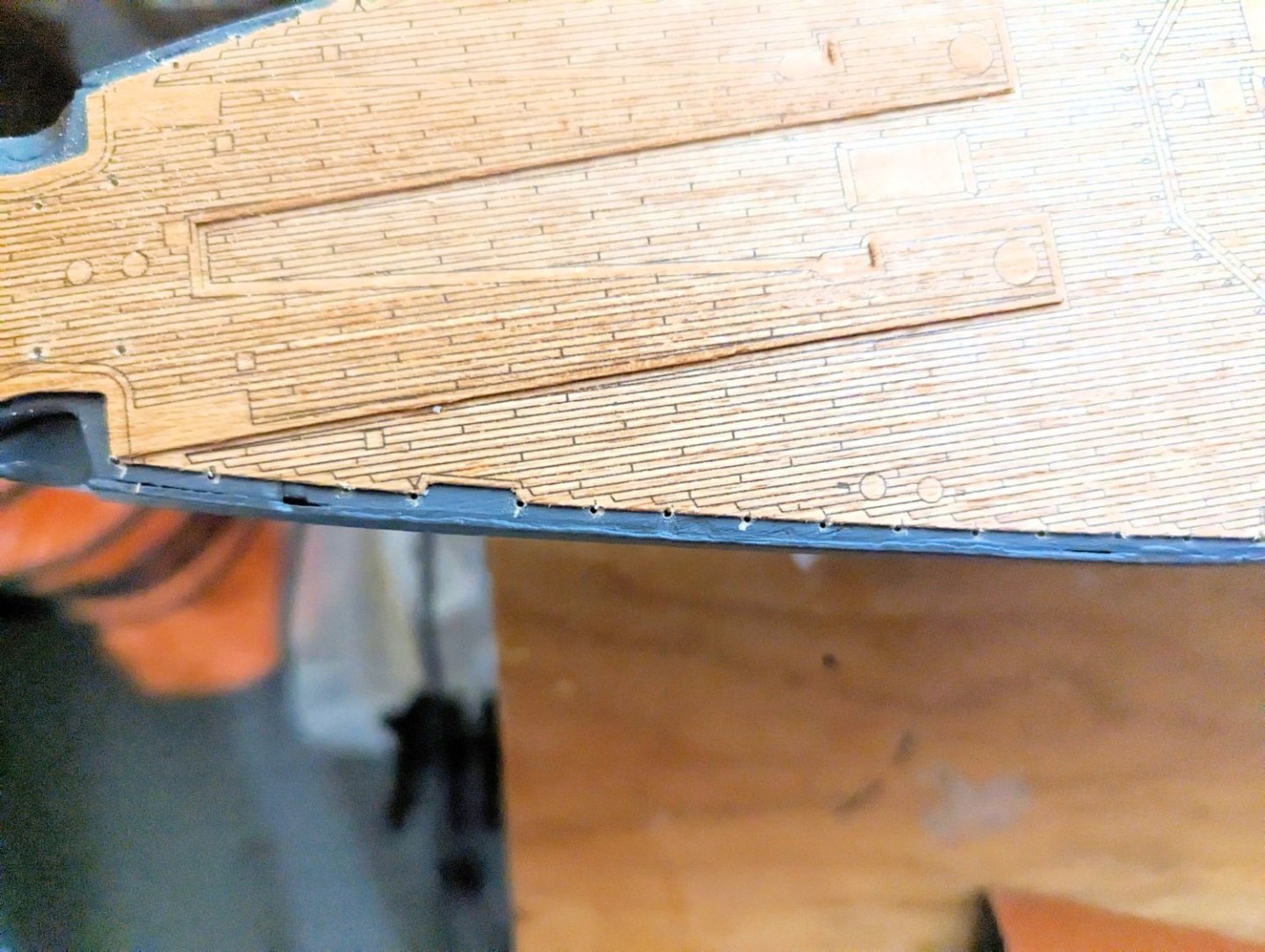
Stanchions (which will go on later) require about 200 tiny holes to be drilled around the edge of the deck. The way my decking fit, there was very little free room beyond it, so for many of the stanchions I'm gong to have to notch a small slot just a bit into the decking to accommodate the stanchion base. Regards, David
-
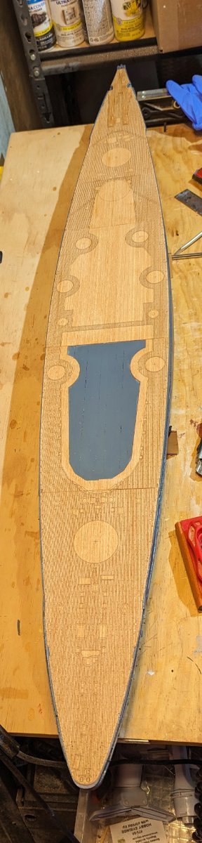
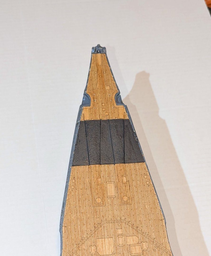
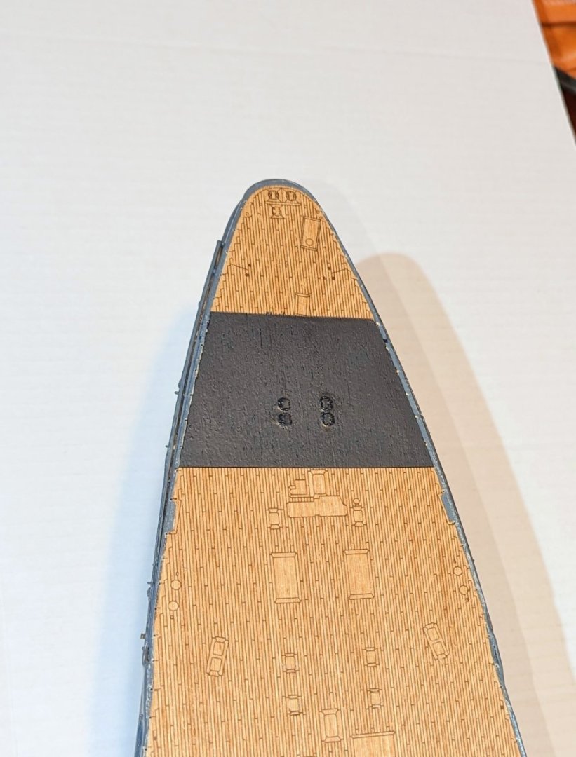
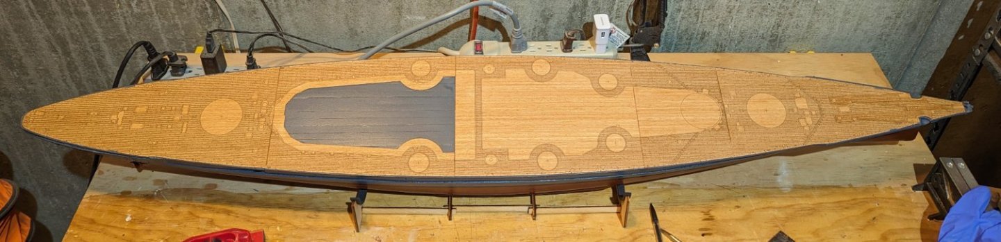
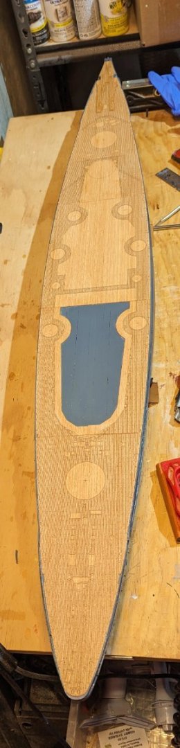
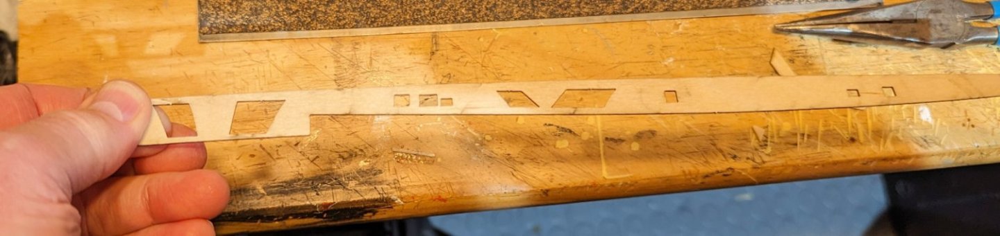
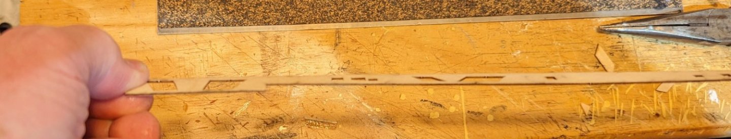
Back from my trip (and finally time zone readjusted), and I've gotten back to the Bismarck. First step from where I left off was to drill the holes under the hull for eventual mounting on a nicer stand than the one they supply with the ship. With that done, I applied the decking, which is thin printed wood sections. The way I did it was to line them all up, sand as required to get everything lined up, and then tape the sections down, checking alignment until I had the whole thing taped. Then I glued sections bow to stern, removing tape and lifting one side, gluing, and then doing the other side. With that done, I varnished the deck. I think varnishing it at this point is important because soon I need to paint two dark gray bands on it, and I want a smooth surface for masking. The unvarnished surfaces are kind of rough wood. Also, if there is any bleed under the mask, scraping it off will look much better if it's on top of varnish. Regards, David
-
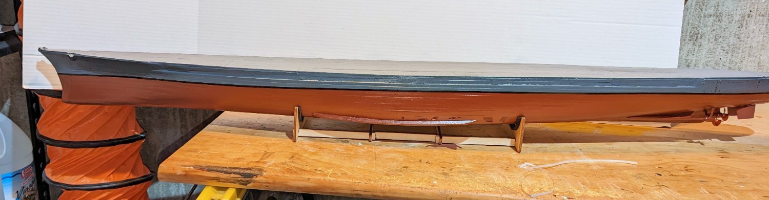
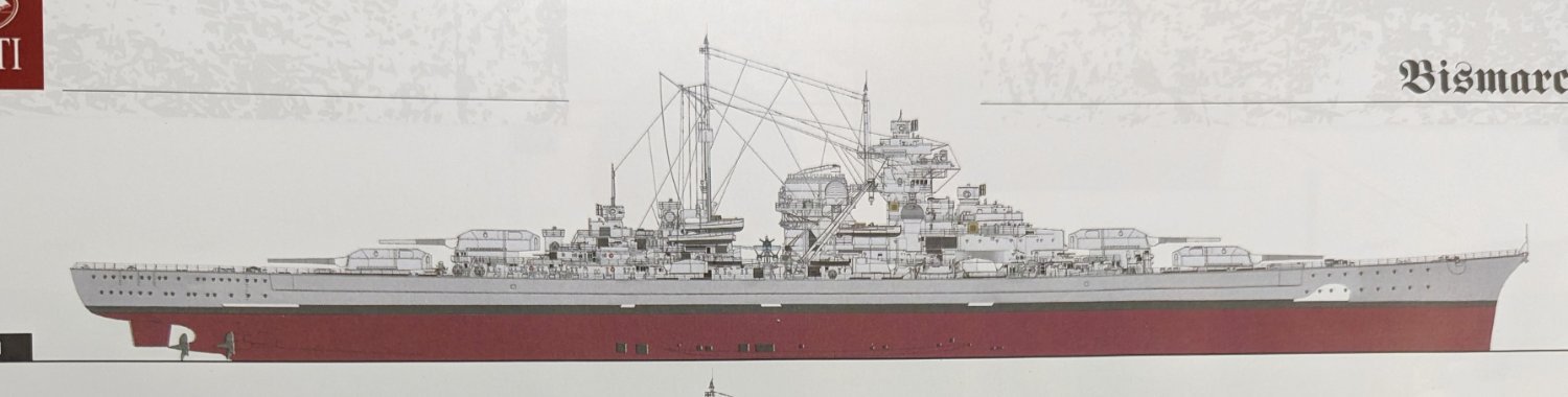
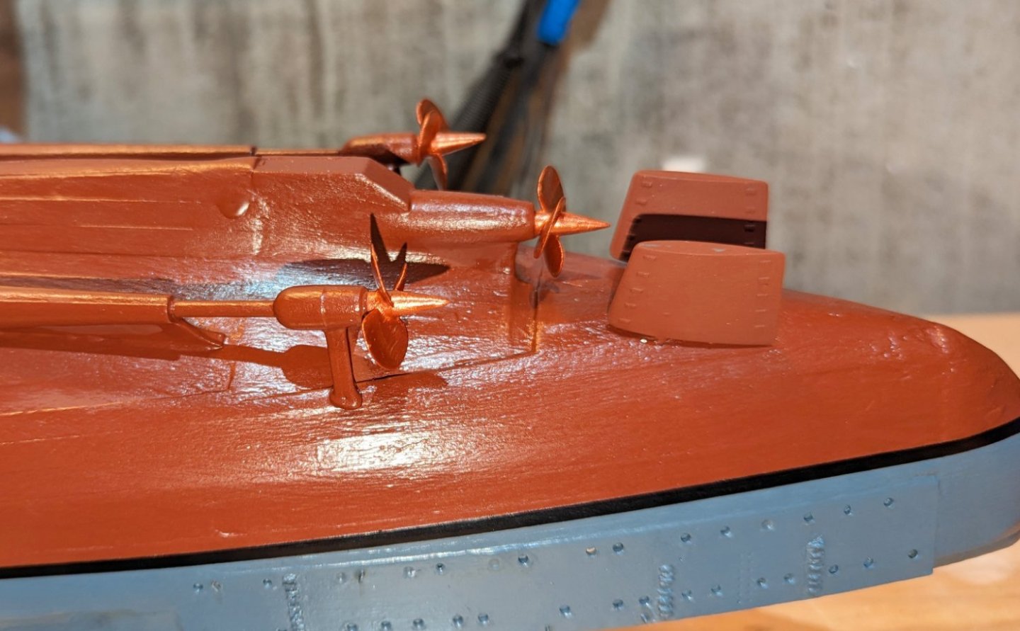
Finished painting the hull. The thin horizontal white patches you see are lighting. Also installed rudder and screws. The screws look the same color in this pic, but they are actually copper-colored. Now my dilemma: I have attached a picture from the manual showing the simplest of the three camouflage patterns. My issue is that I really don't like the way this looks. So after some deliberation, I'm going to skip the white coloring. I really respect those of you that pay close attention to historical accuracy, but I'm going to skip the white designs. This will be my last post until late February. Going on a long winter trip. Regards, David


-
So I flipped the model over and did the last ladder -- the one in the center. Tried a new approach, which is to spread out some glue and dip the ladder rung points in it and then insert, and then you can see the difference. I wish I had tried this earlier. So with this I'm now ready to paint the lower hull red-brown. Regards, David


-
Over to the other side and up the learning curve. On this side I did two things: (i) Drilled out the holes in advance, and (ii) Used my super bright LED headlamp so I could see the holes clearly as I was installing the rungs. Worked better. The first picture reflects all of the skipping of the drill bit on the metal surface. The second one, now painted, shows the "glue globs" between the rungs. So I took a needle file to it and cleaned it up (third picture) as best I could. As they say, "It is what it is." I only have enough rungs left to do three ladders on each side. My loss rate decreased but was still greater than zero. So now I'll go back to the other side and add the third ladder, and paint it. There are also some very small eyebolts and keybolts that have been added. Not sure if you can see them or not. Regards, David

-
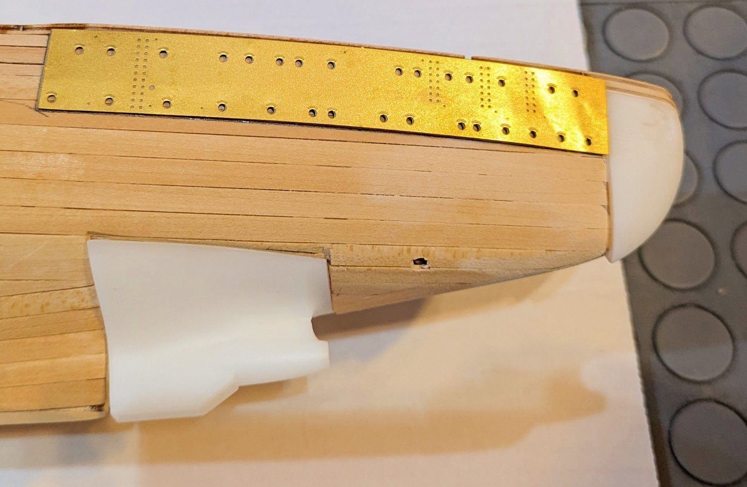
I'm applying the ladders to the external hull at the stern. The way Amati has designed this is that you do it rung by rung, into pre-drilled holes in the brass plate at the stern. The issue is that the rungs are fiendishly small. So they are very difficult to grip with tweezers, and of course, they pop out of the tweezers. If that happens, they are almost impossible to find on the floor or even on the workbench. As part of my learning curve I've now put a white paper towel under the stern area, and if they pop out onto that you can see them. But I've lost 6 already, and so I'm down to 2 spares to cover the remaining ladders. What you see is the two ladders I've done on one side. As you can also see, there are holes for two more on this side for a total of four on a side. Counting what I have left, if I don't lose anything else, I could make it with two spares left. But not confident in that. So I'm going to flip the model and do these two ladders on the other side. That will leave four to go. I'll do two (one on each side), and then assess my technique and spares supply to see if I can do the last one. One thing that helps is to drill out the holes. Then put in the rung without glue, then drop on some glue. Slow going as you have to wait for the glue to dry, or use accelerator. So now I'll attack the same two ladders on the other side and see if I've learned anything, and I'll report about that. Regards, David

-
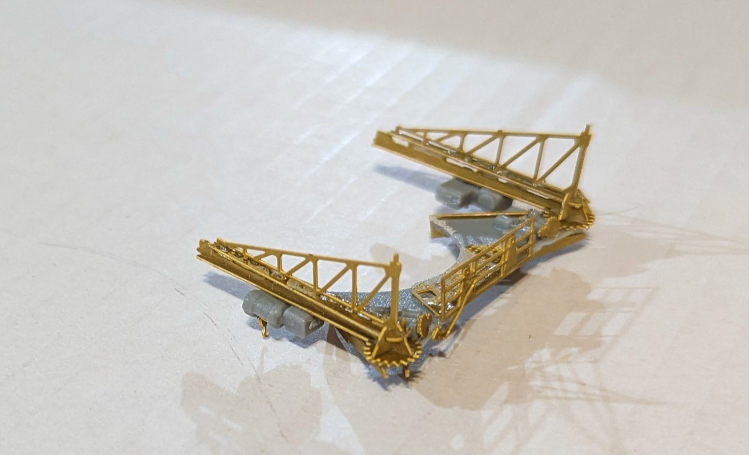
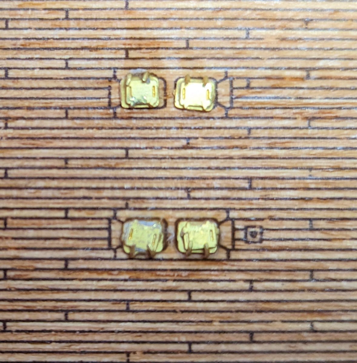
These brass pieces go into cutouts previously installed in the hull. They are meant to represent vents, I think. They will be painted over with the red-brown that's used on the lower part of the hull. Regards, David

-
Hof: That's an interesting idea, which I will save for my next model. I have moved on from trying to further smooth this out since, as I noted, it looks fairly smooth from normal viewing distance. Thanks for the tip! Best regards, David
-
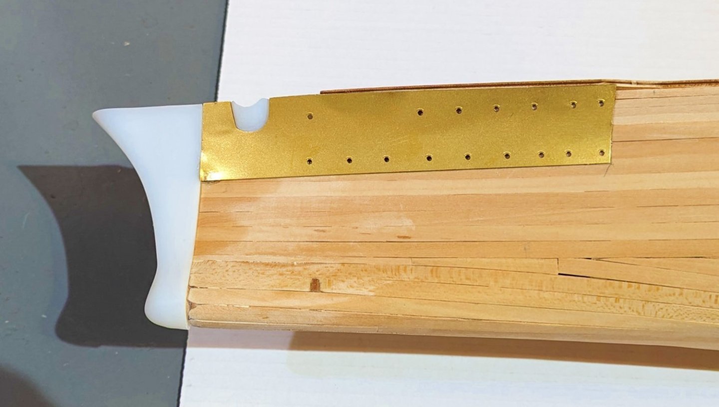
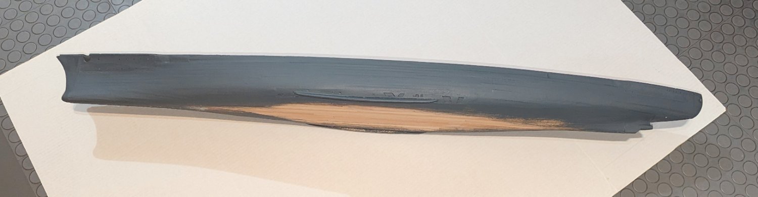
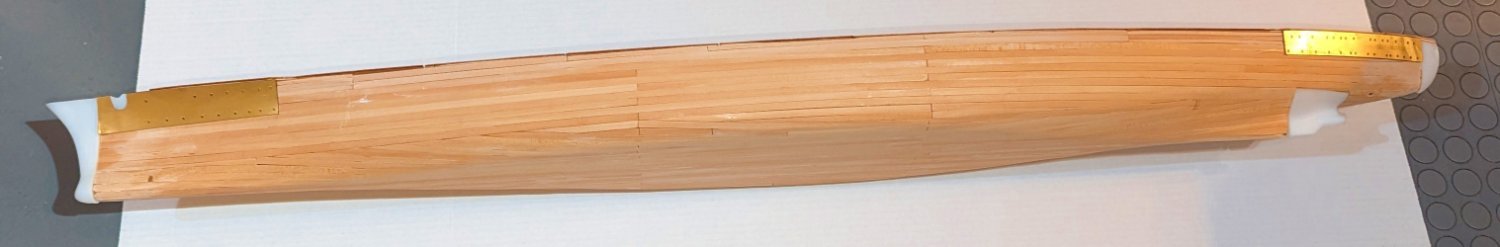
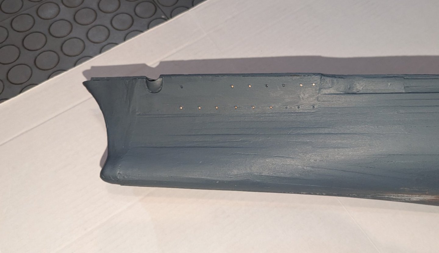
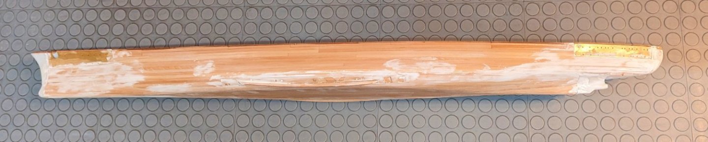
What you see here represents about 5 coats of paint, and a bunch of follow-up puttying and sanding. I have a few comments about this hull structure: From a distance (full hull picture) it doesn't look too bad, especially in the lighting I'll have it shelved on (I tested that). You'll note that I didn't finish the bottom as that's going to be red-brown below the waterline. But up close, the brass plates at bow and stern are troublesome. Try as I might (and we have to acknowledge the limits of my woodworking skills) I couldn't get them to "disappear". Again, from a distance they don't look too bad. But if I had it to do all over again, I'd be tempted to skip the brass plates and second plank right over where they are, to give a uniform look, and then use the brass plates as templates to drill the portholes. I think I'll give bow and stern one more coat of paint, as that seems to help them "disappear". Regards, David


-
Second planking done; sealed with a coat of varnish, then putty applied. I took this against a gray background so you can see the putty. Now a first coat of paint, and we'll see where the imperfections really are. I'm going to brush coat this -- it's too big for my spray booth, and it's too cold outside spray it in the garage. Regards, David
-
Now in the middle of second planking. As the hull curves from side to bottom, there is a piece that needs to be installed. It comes off the laser sheet flat, and has to adapt to the curve of the hull. I used my steamer, and a bunch of CA glue and accelerator. The wider side pieces are fairly easy to shape -- but the narrower center is a bear. Regards, David


-
The model uses brass bulwarks at the bow and stern -- I think probably to define the portholes cleanly. There's also a resin piece added in these pics on the lower stern. Next step is second planking. Regards, David