hamilton
-
Posts
1,933 -
Joined
-
Last visited
Content Type
Profiles
Forums
Gallery
Events
Everything posted by hamilton
-
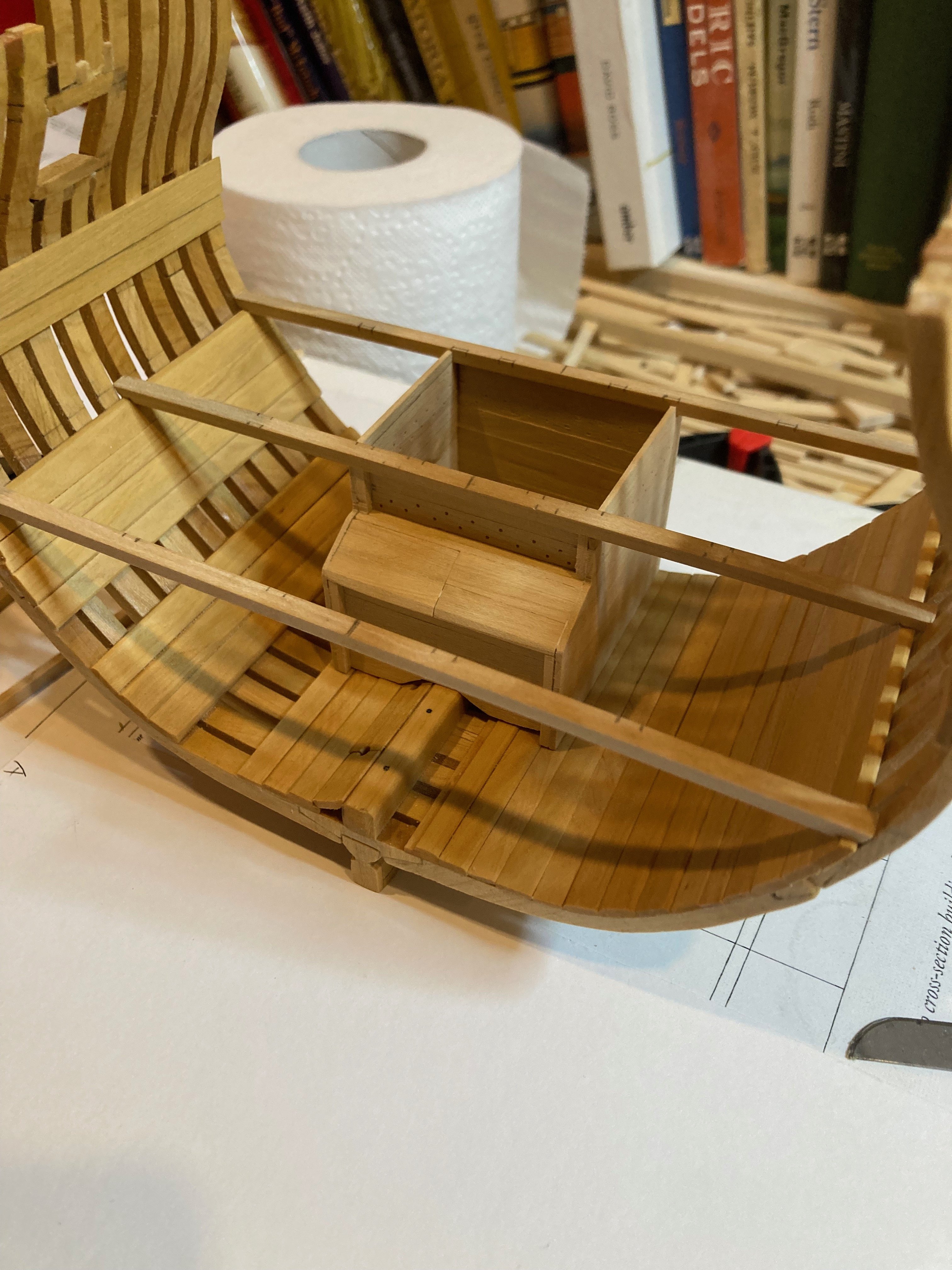
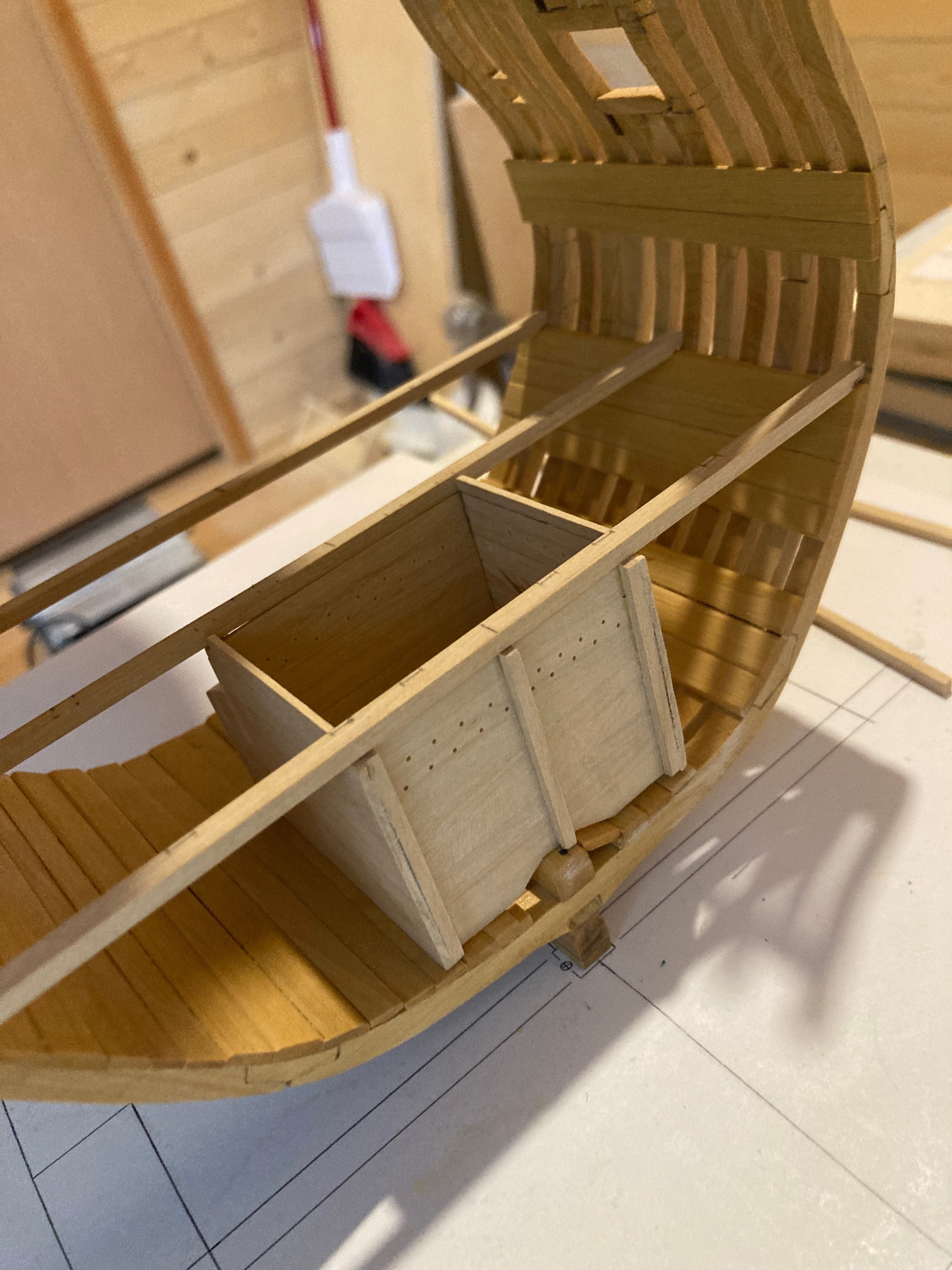
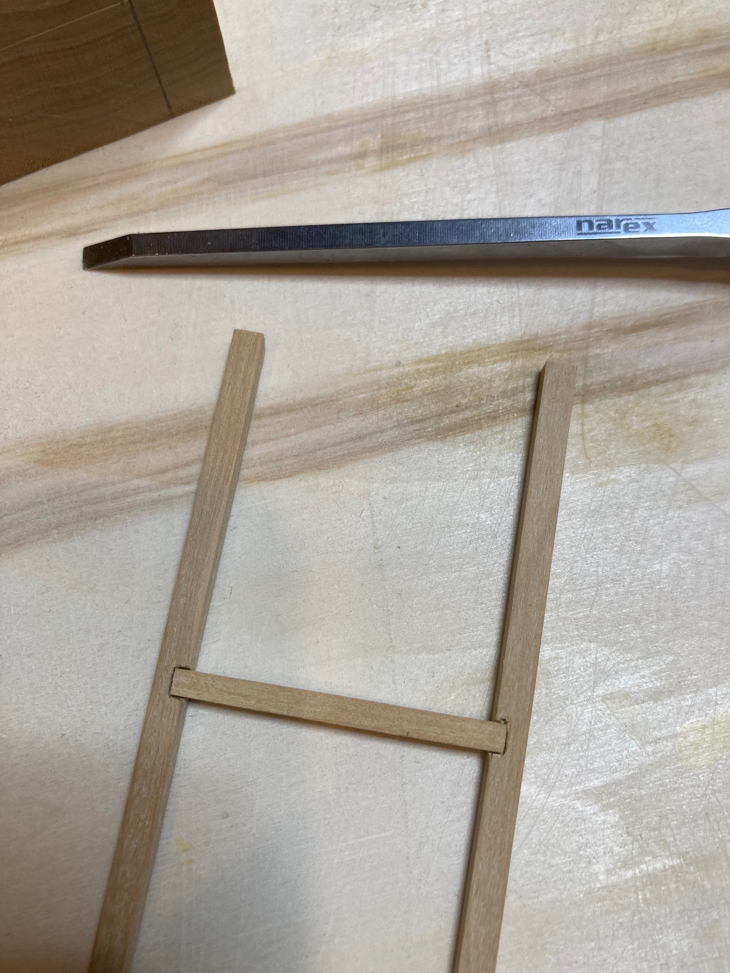
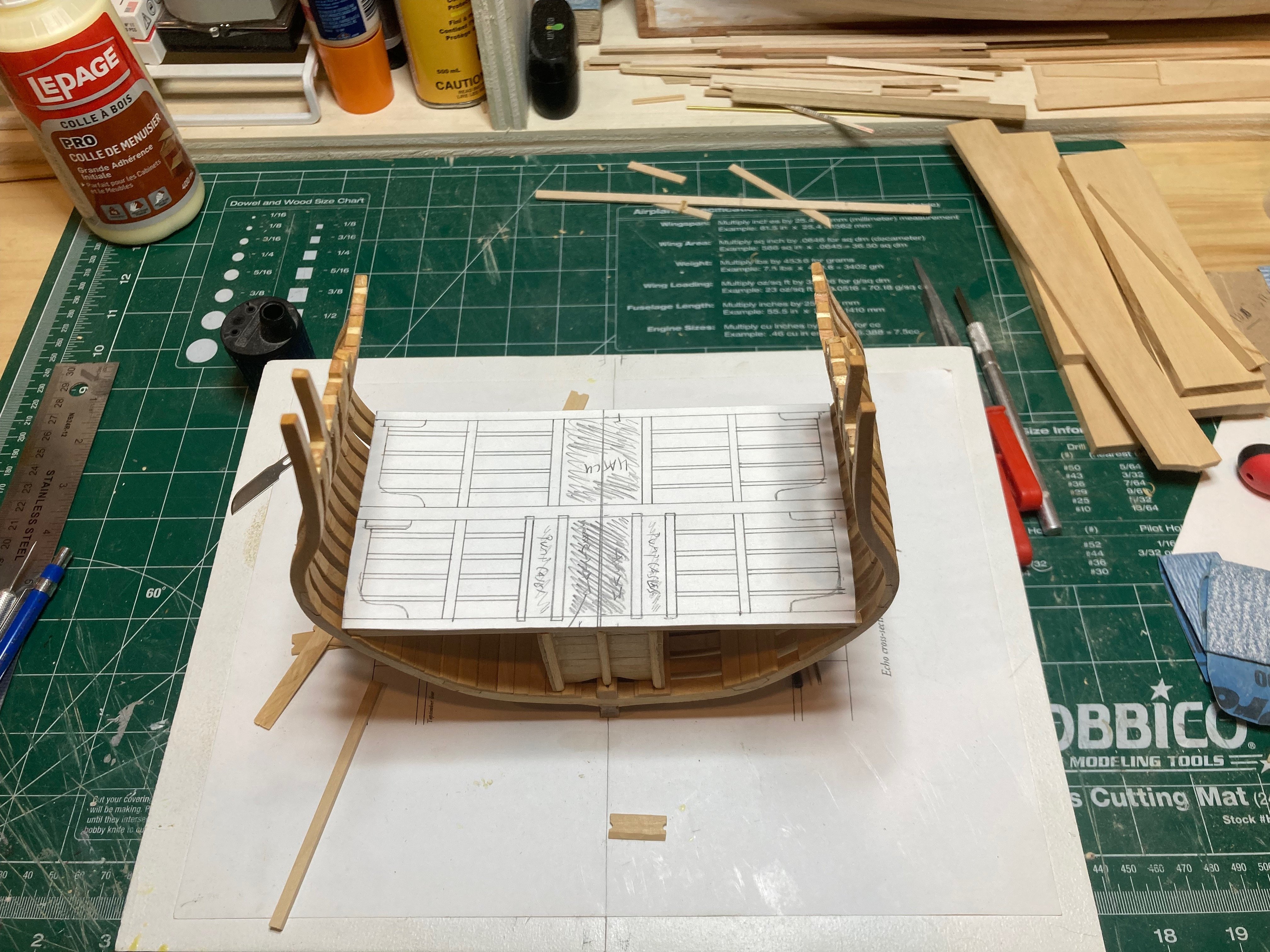
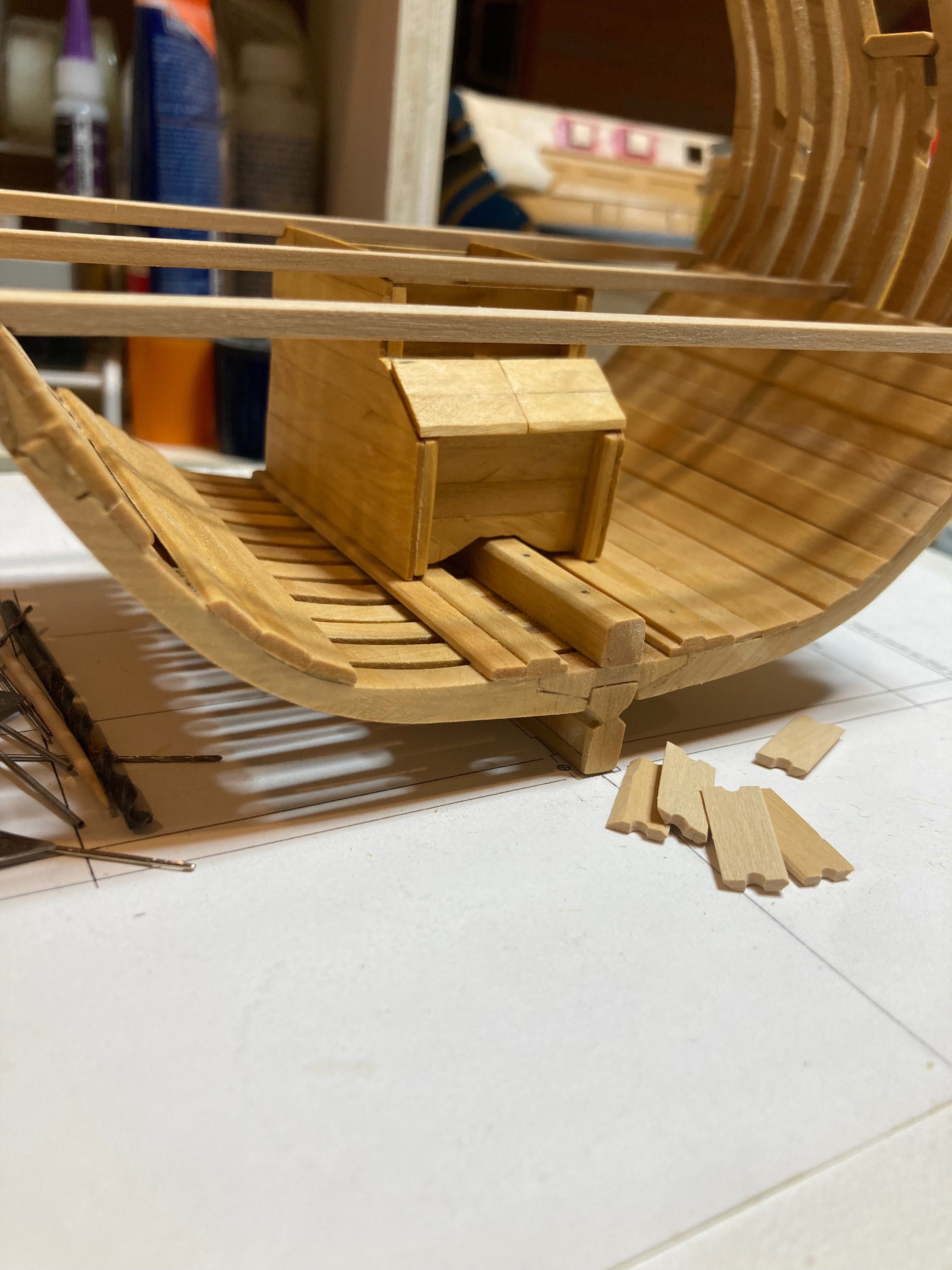
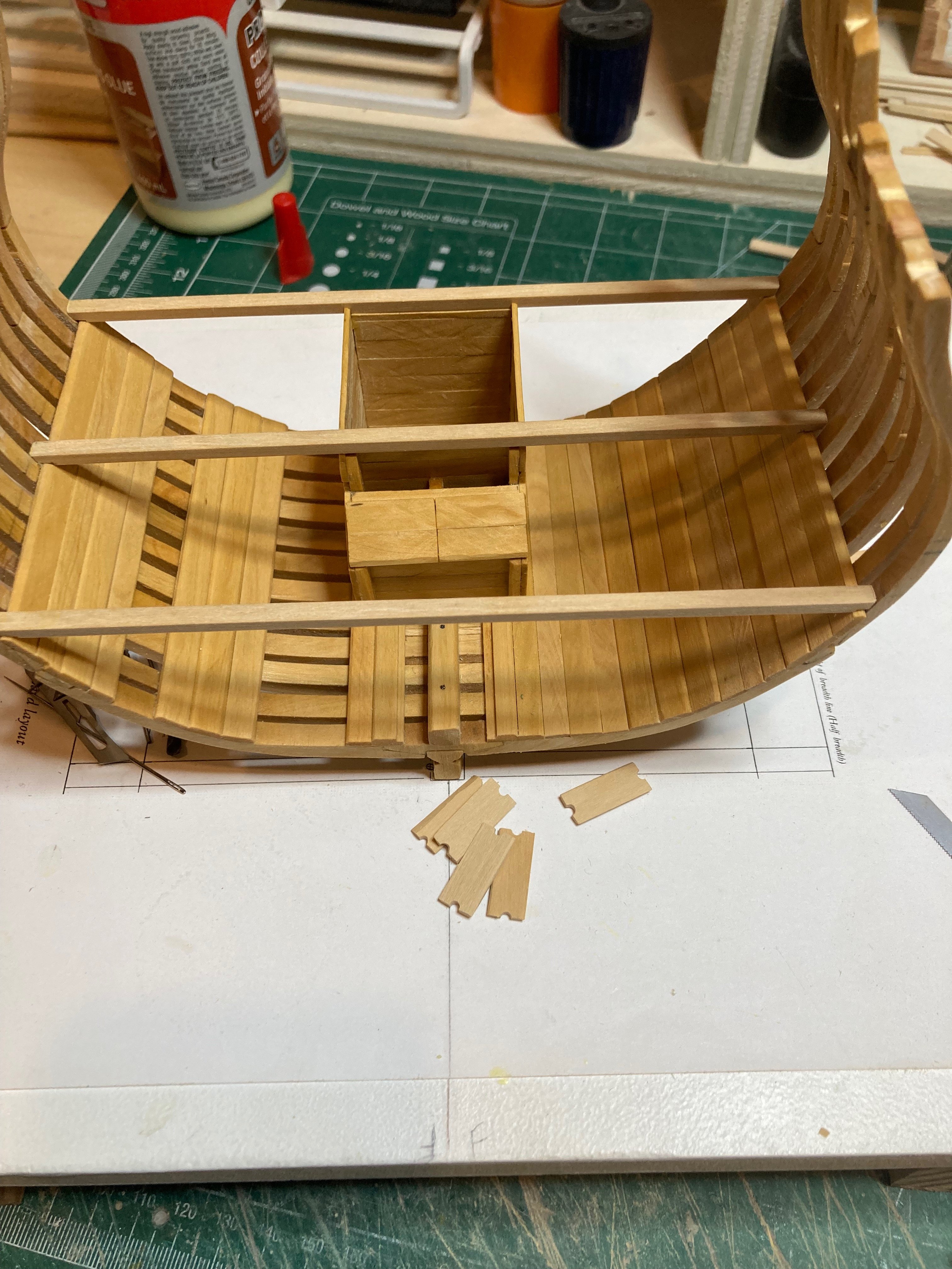
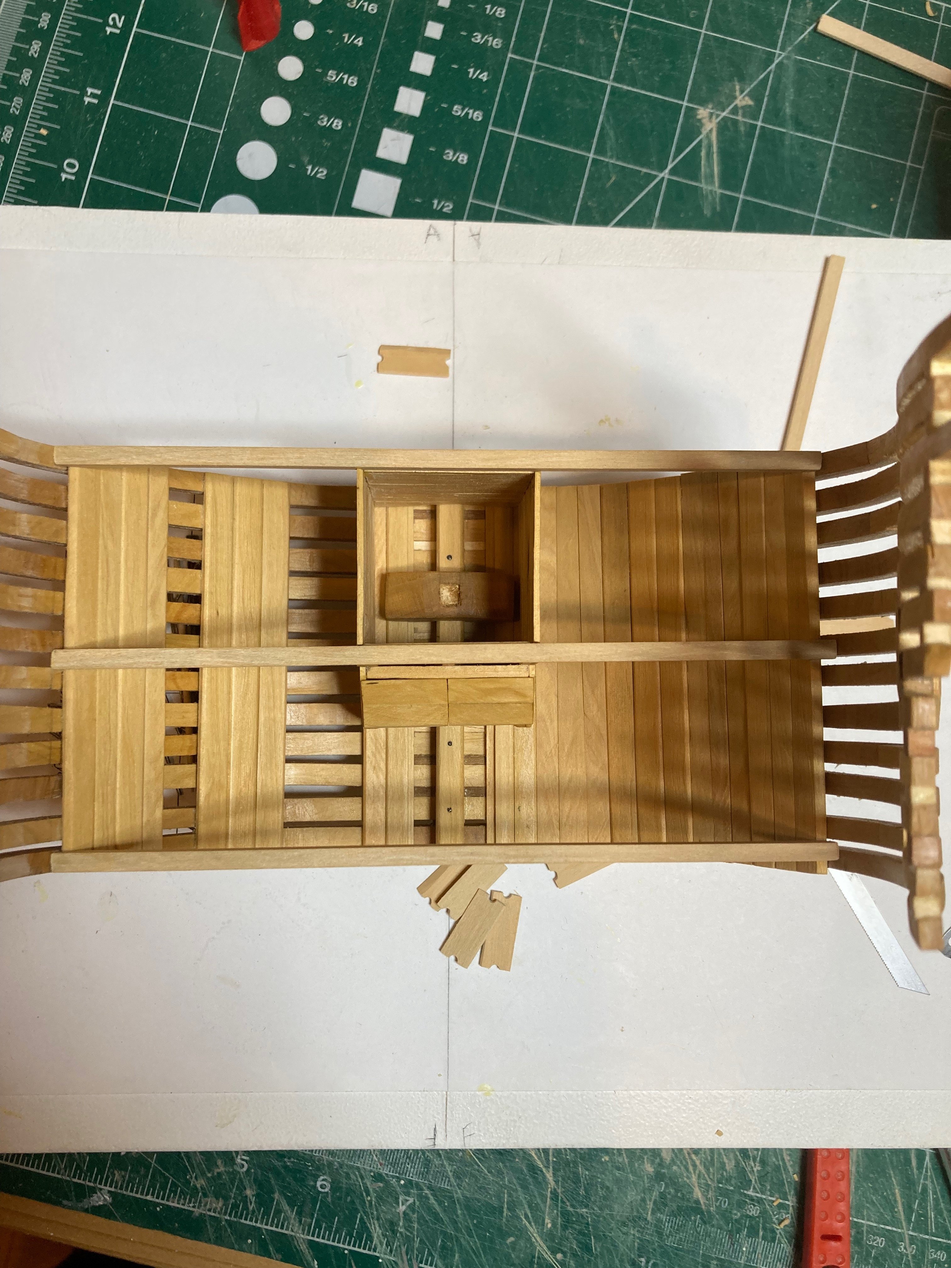
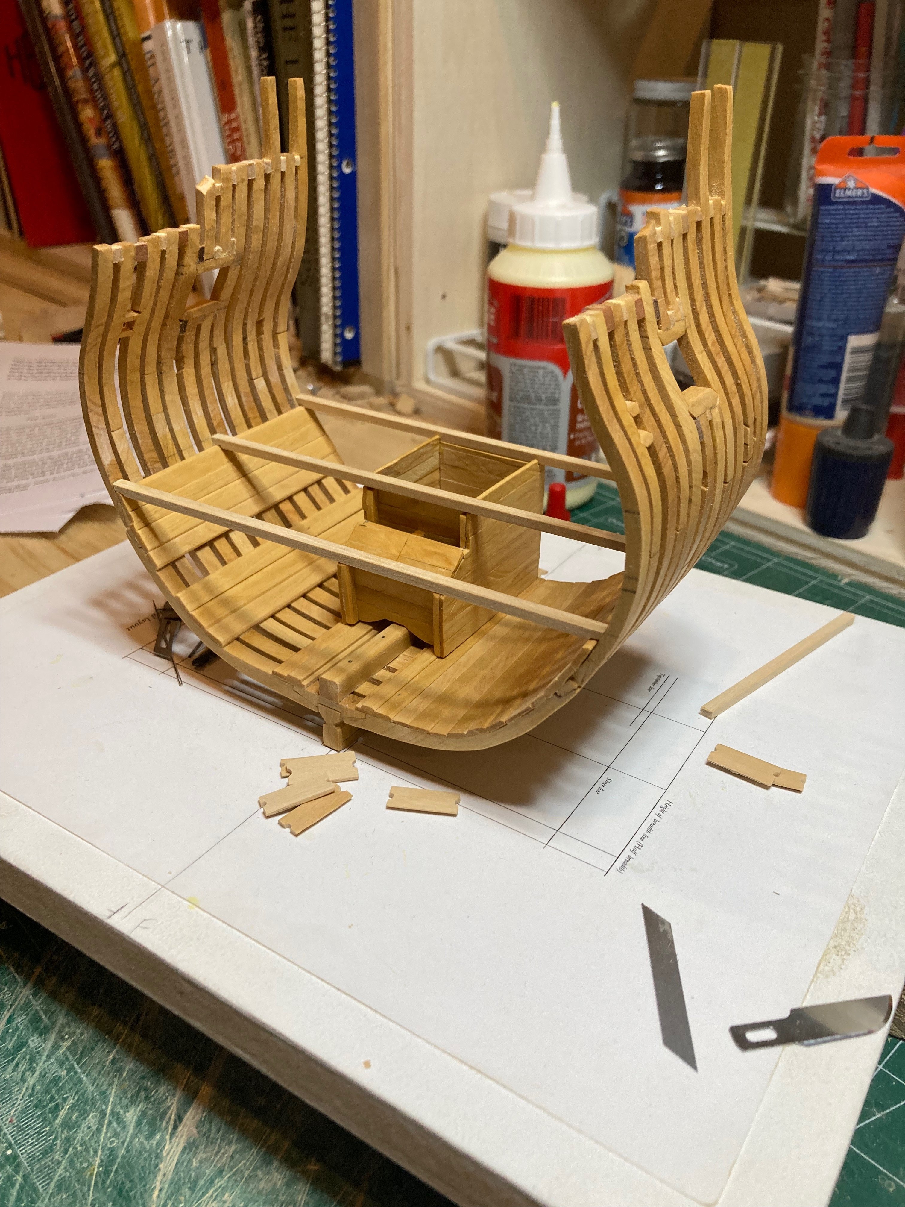
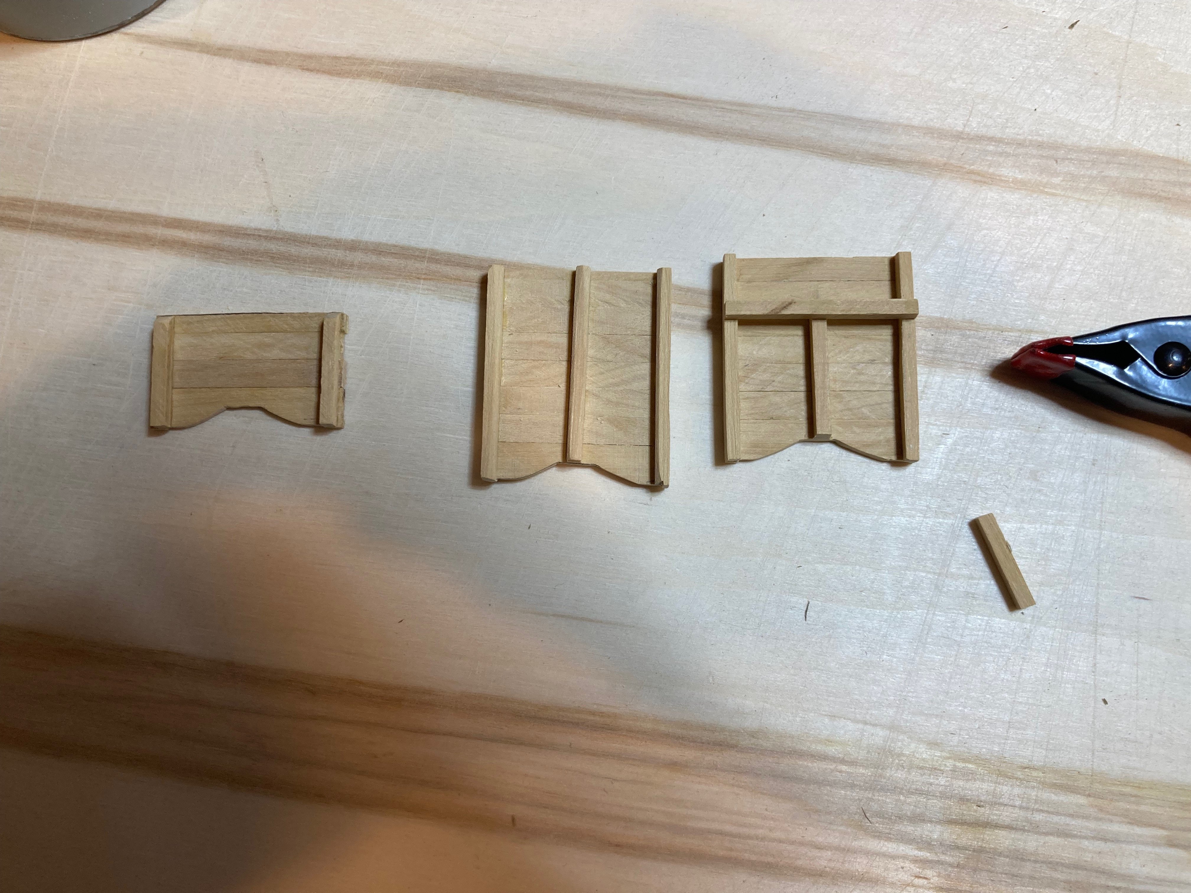
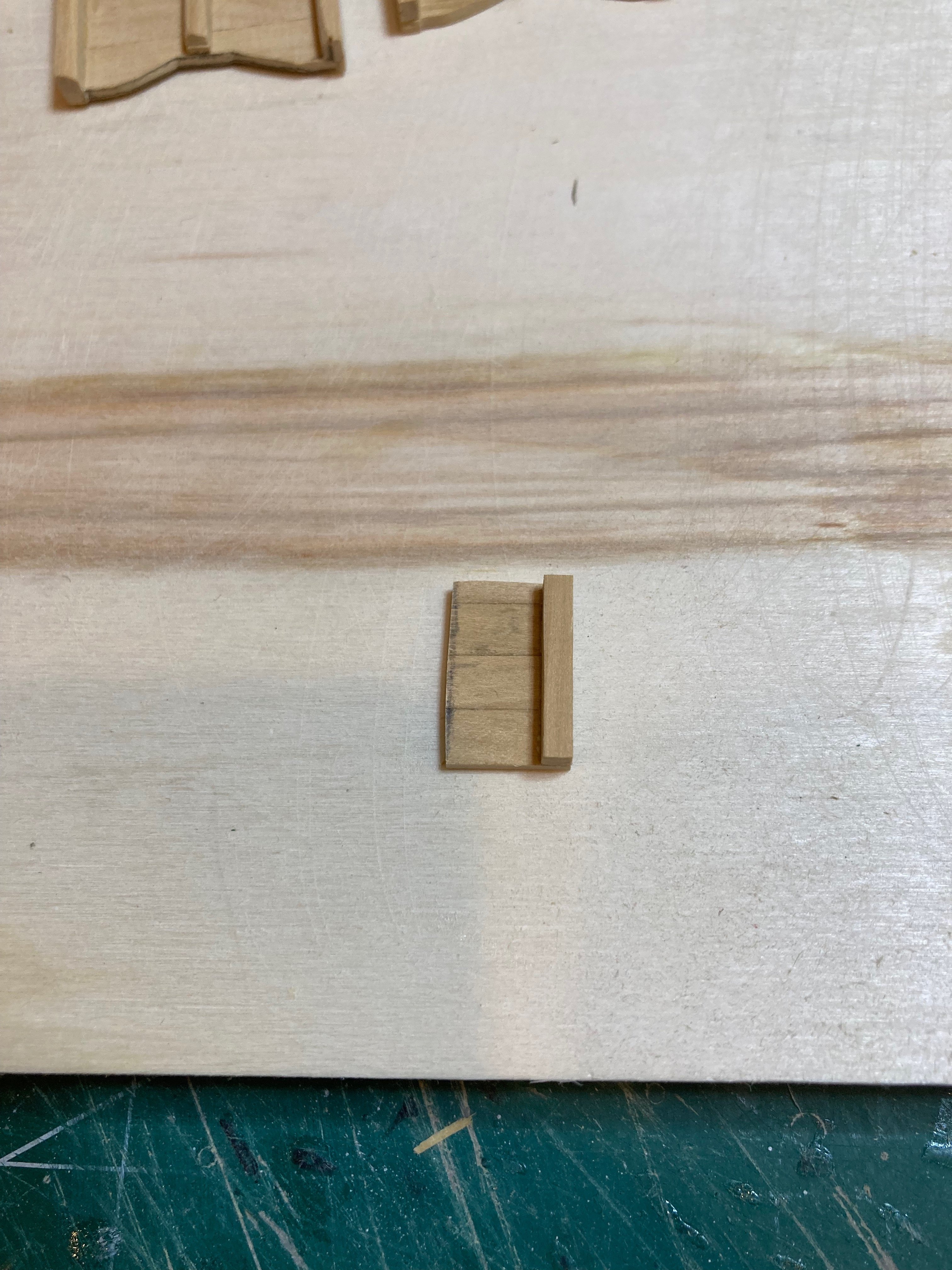
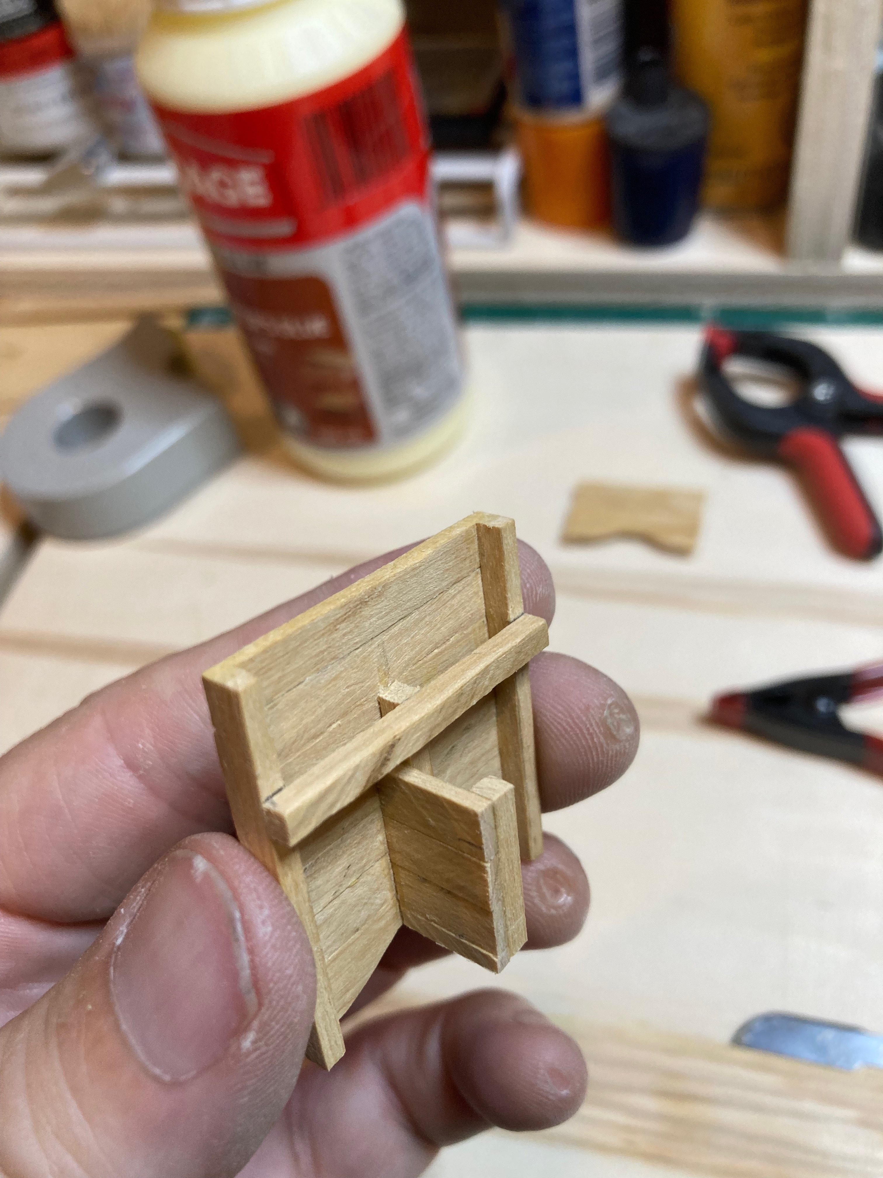
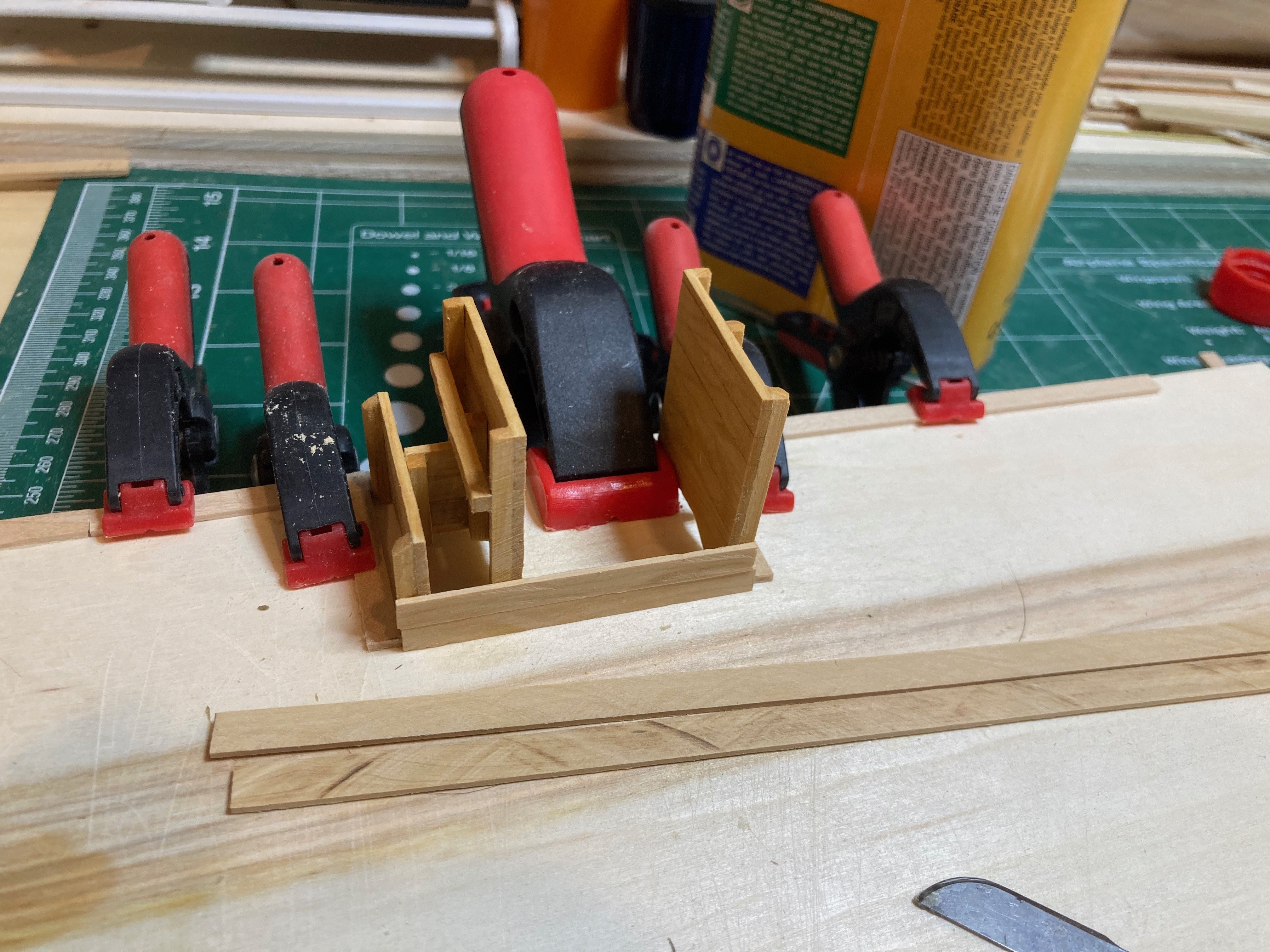
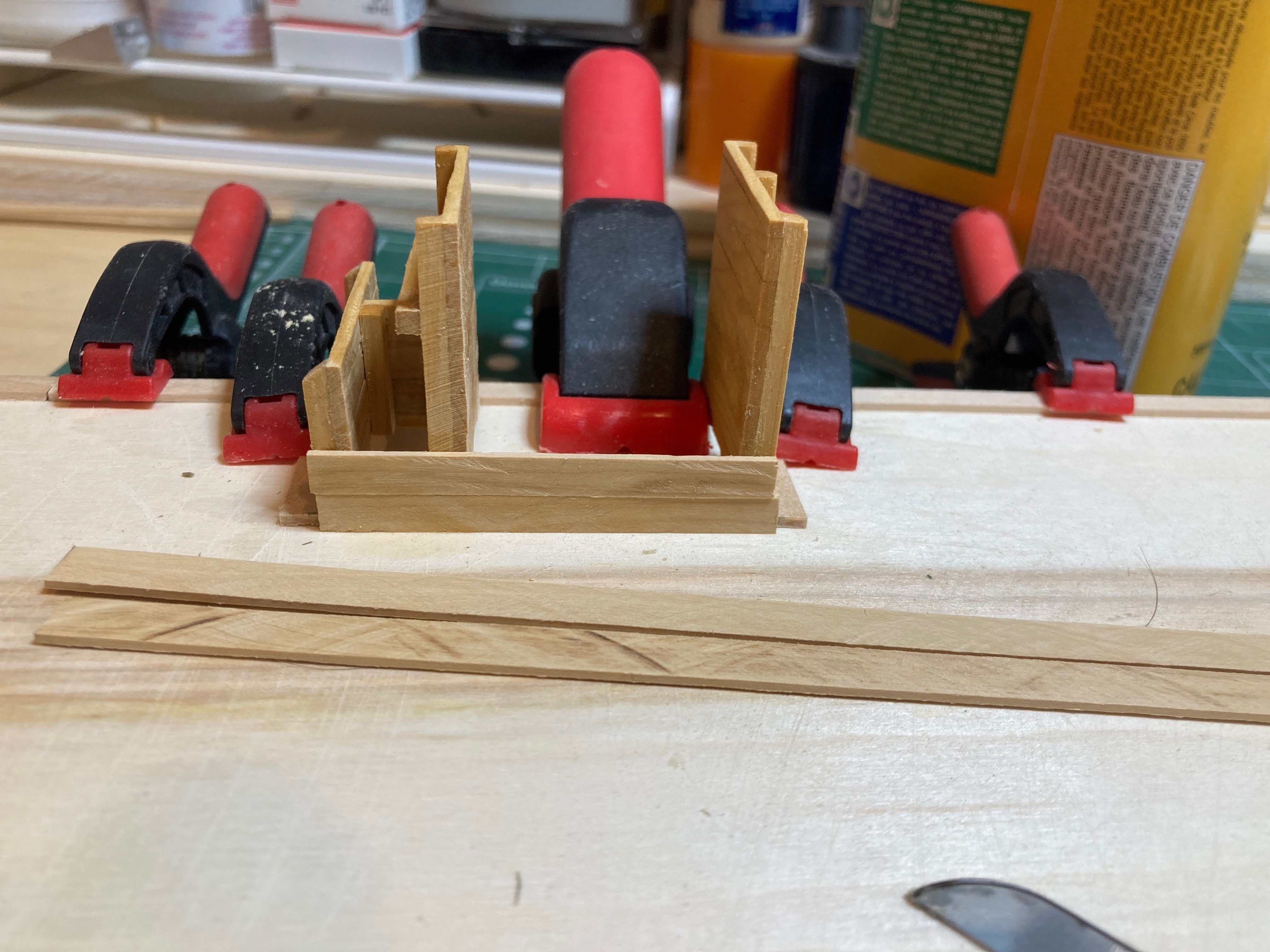
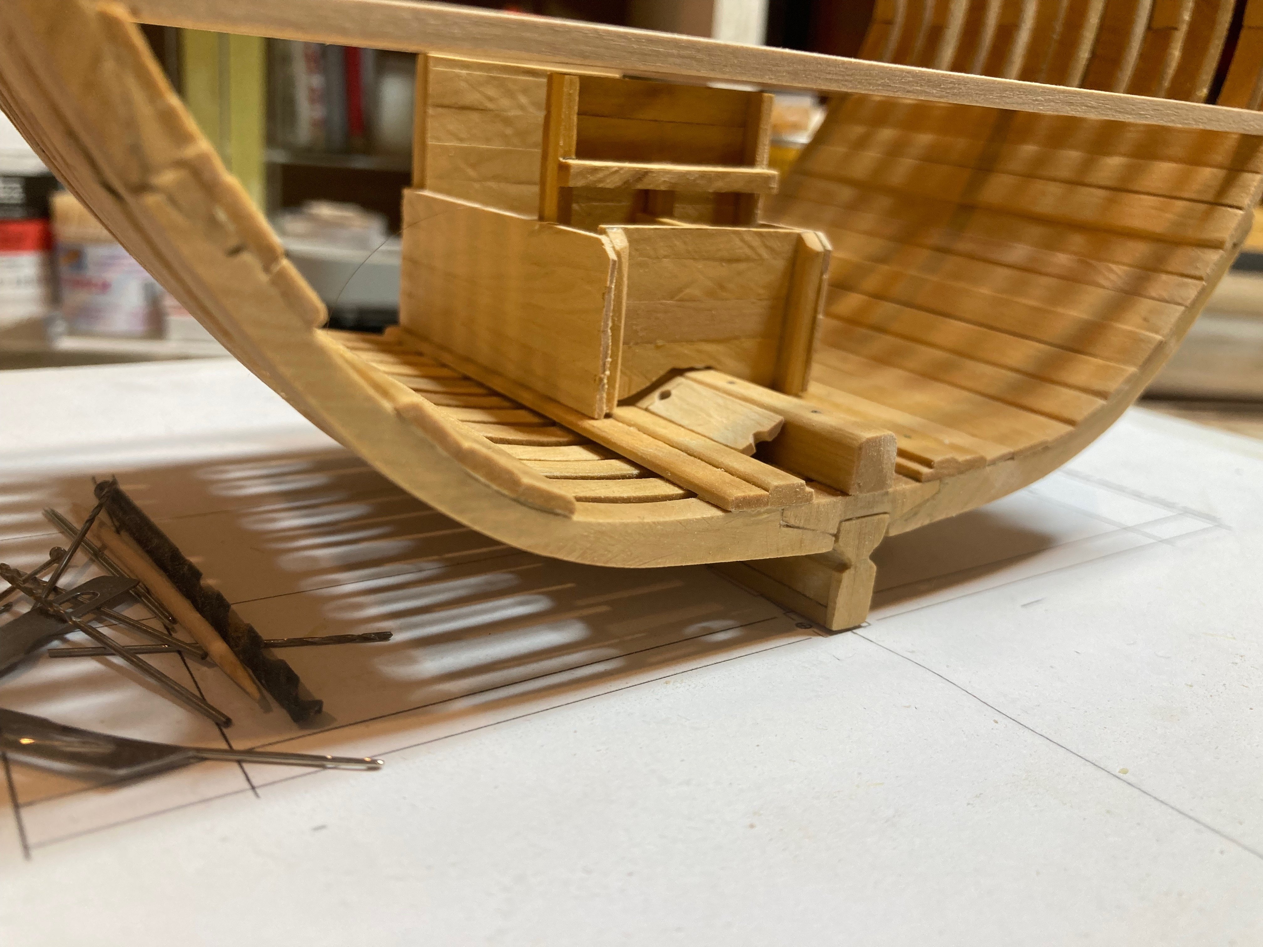
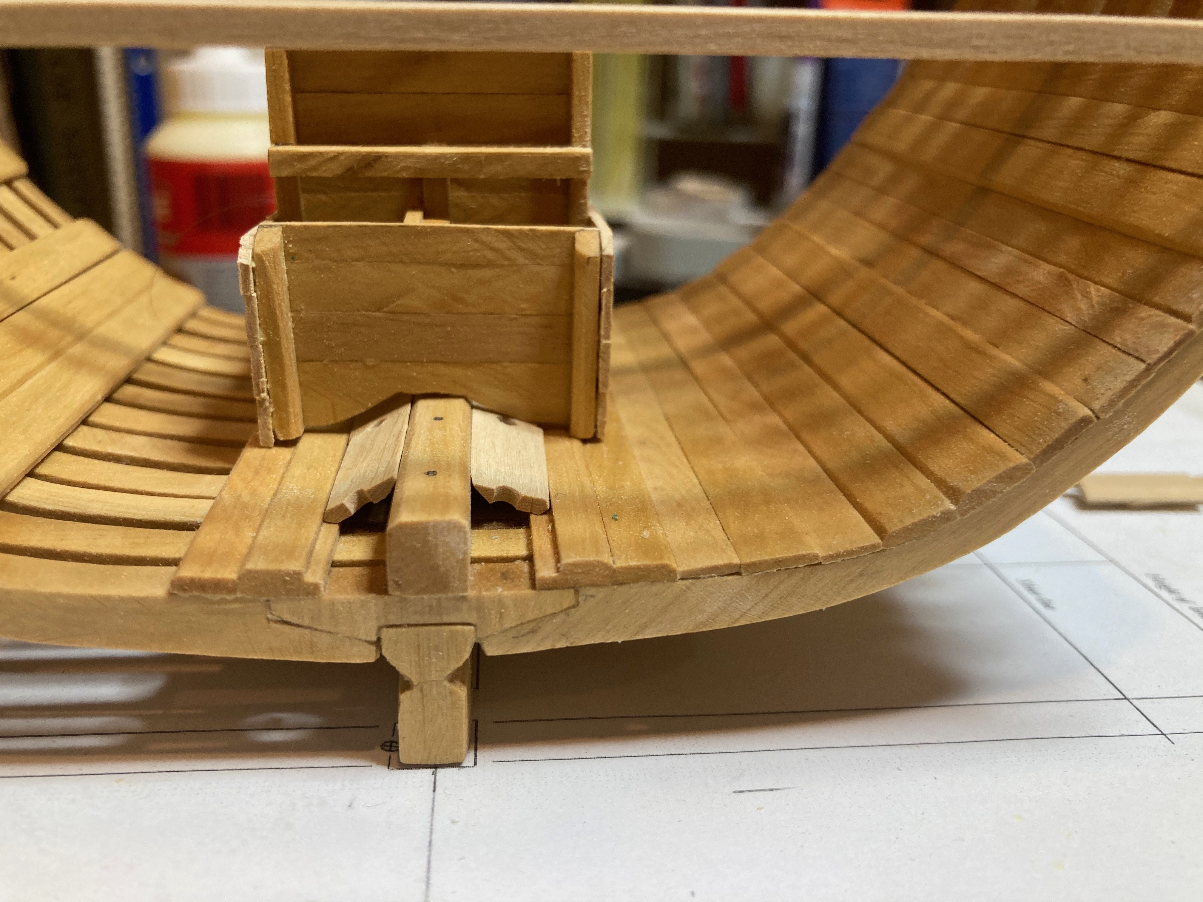
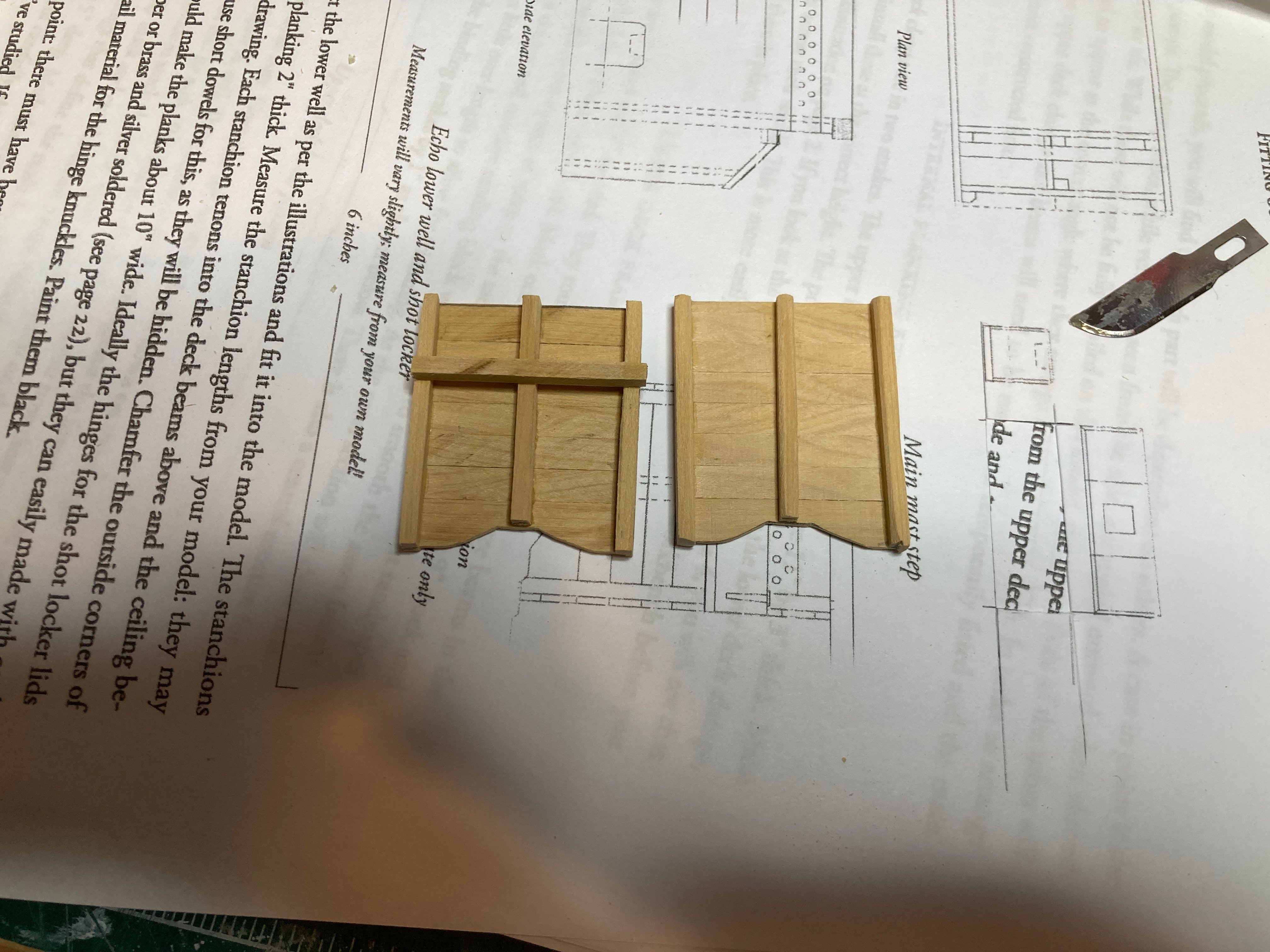
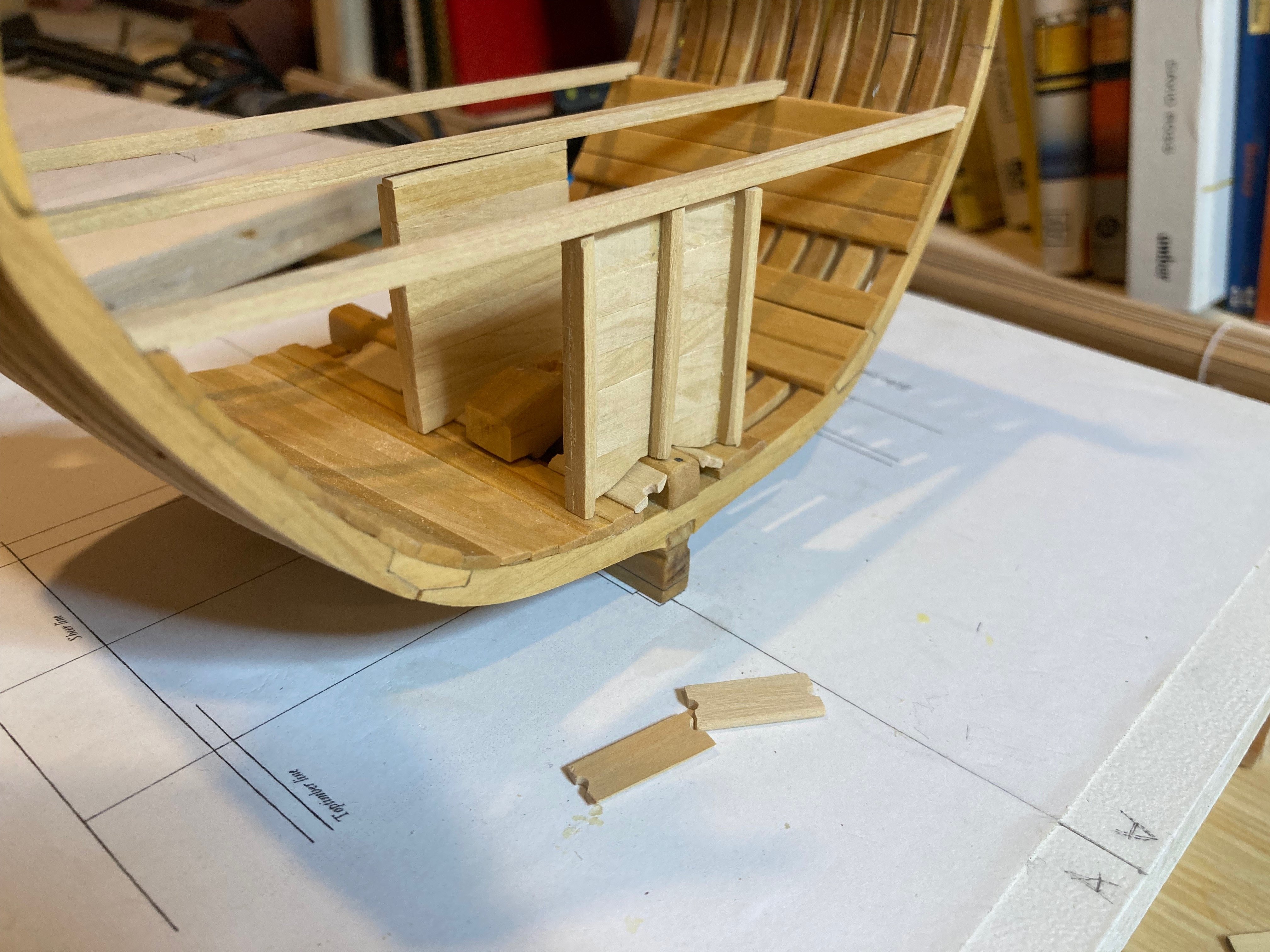
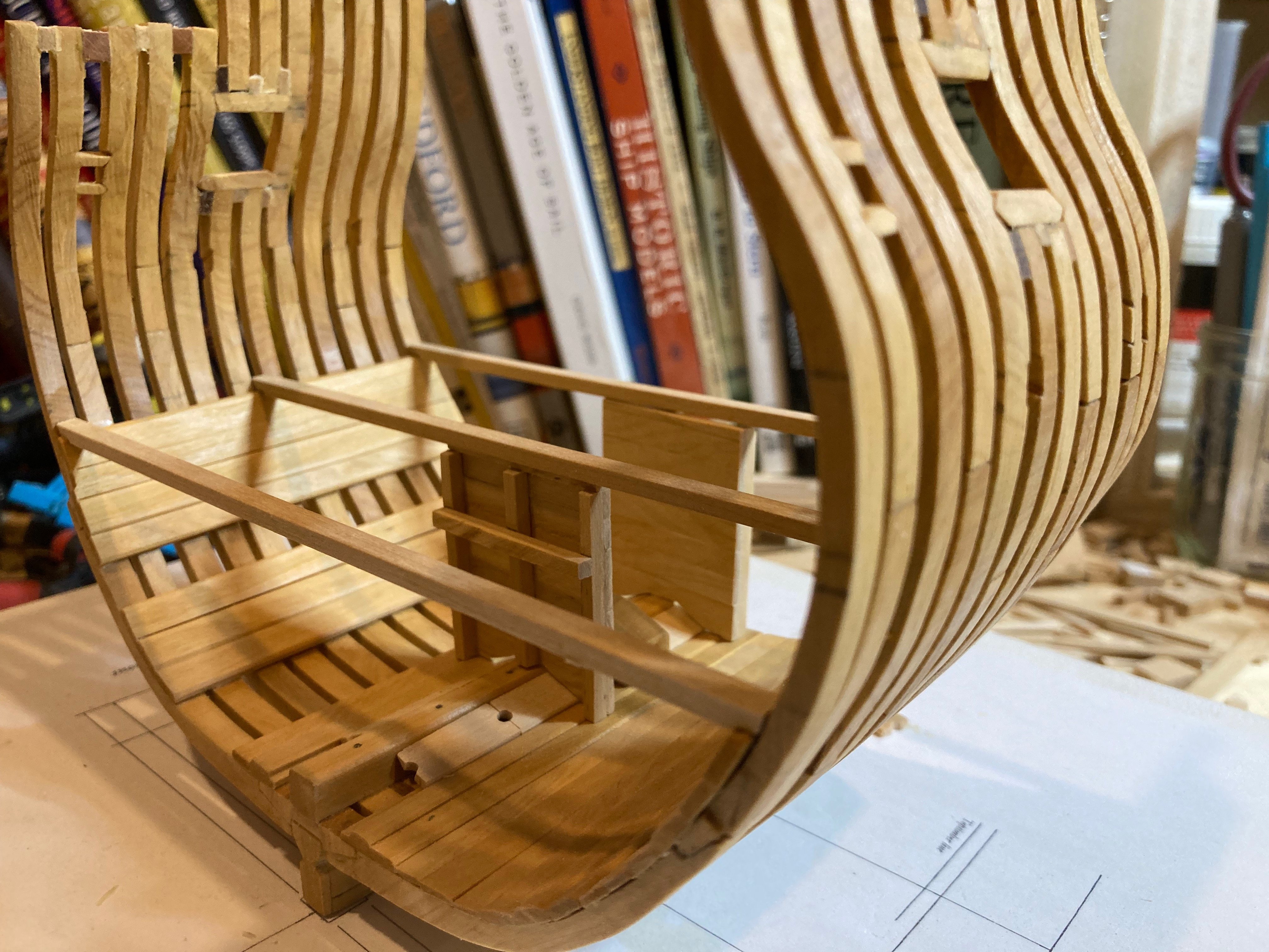
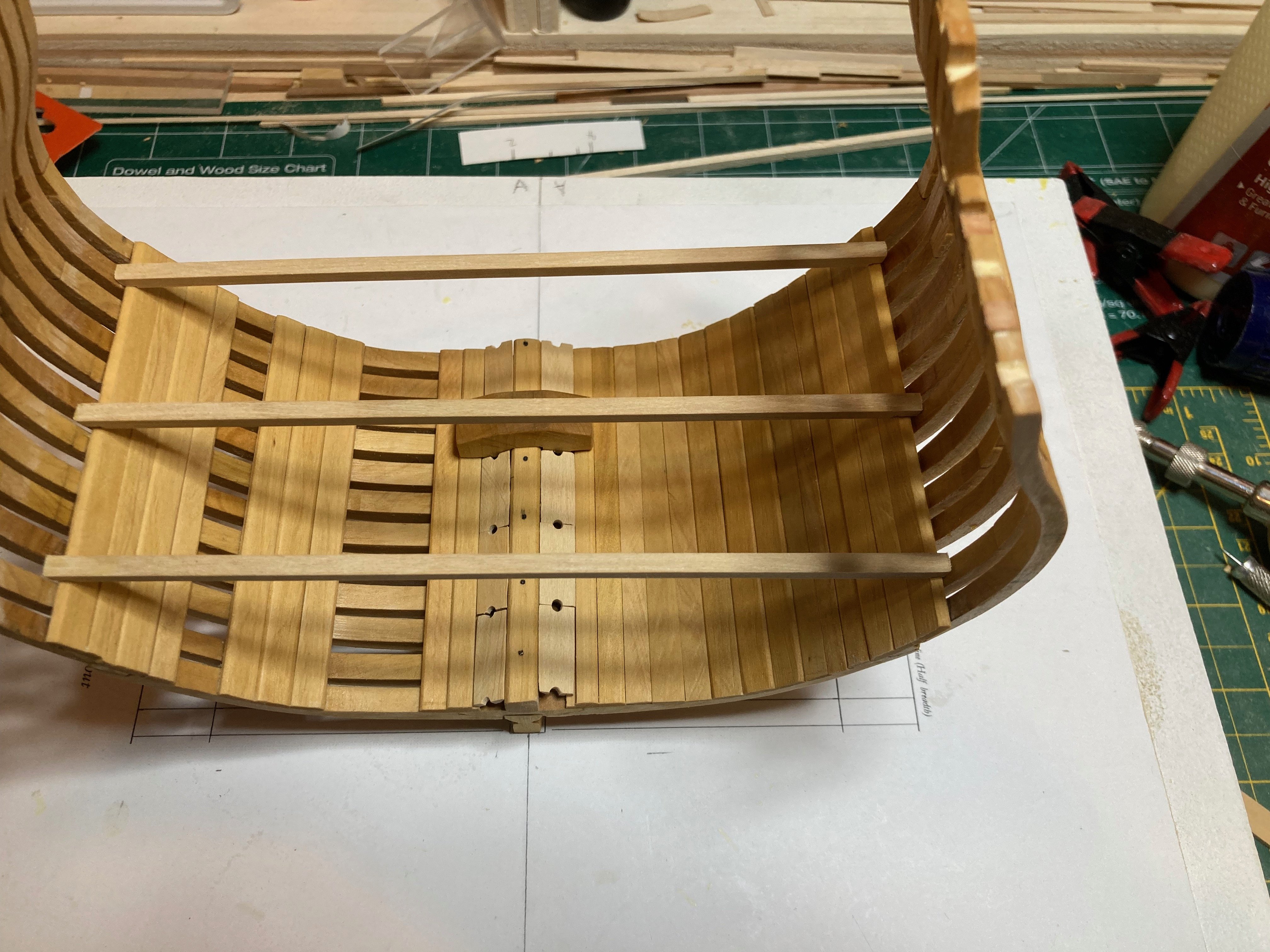
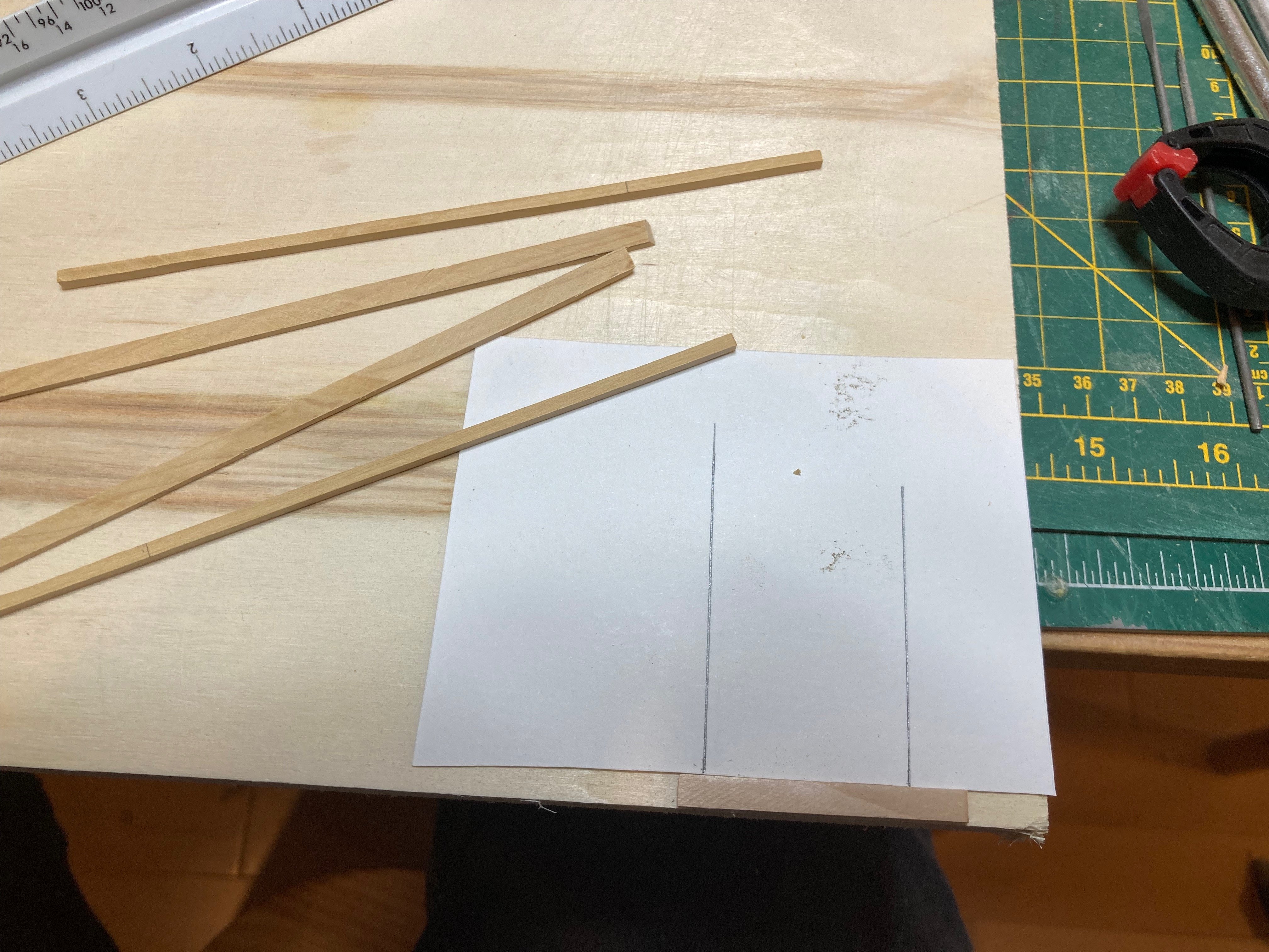
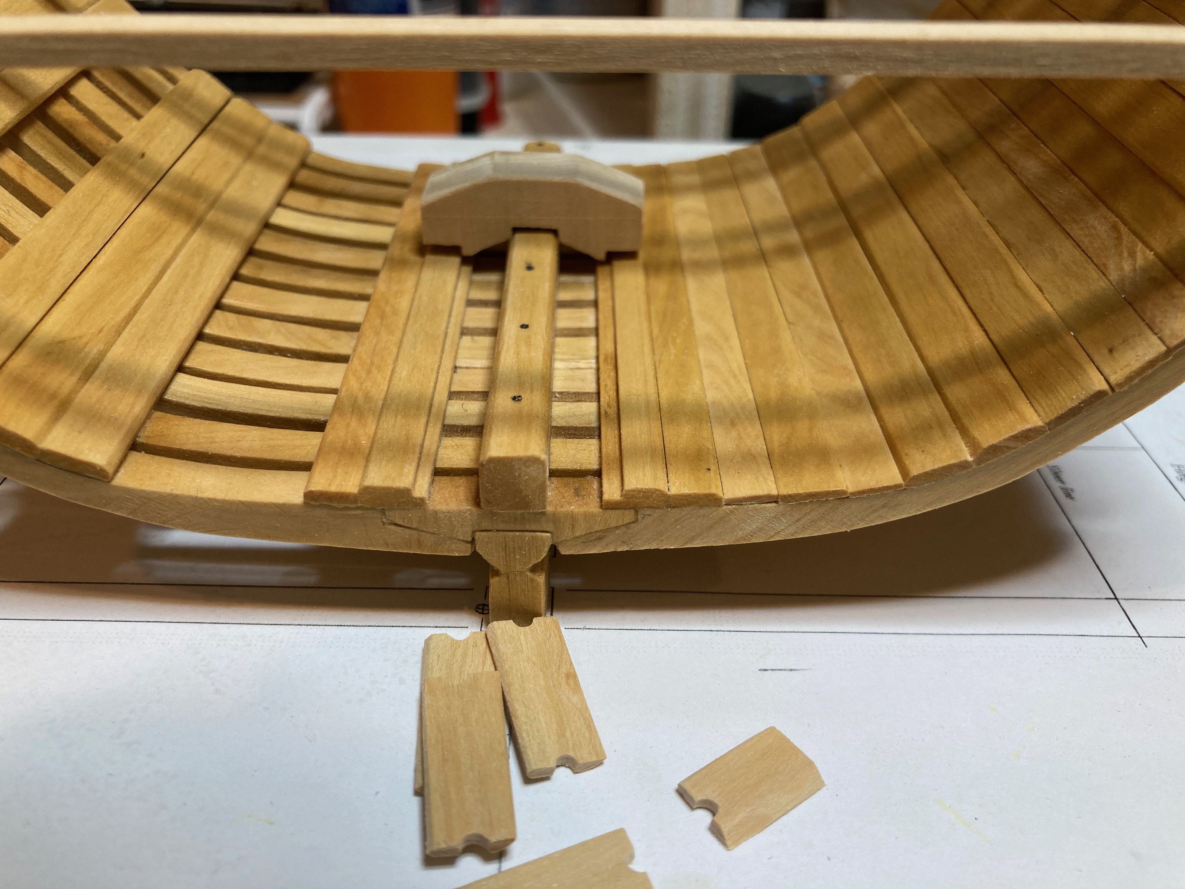
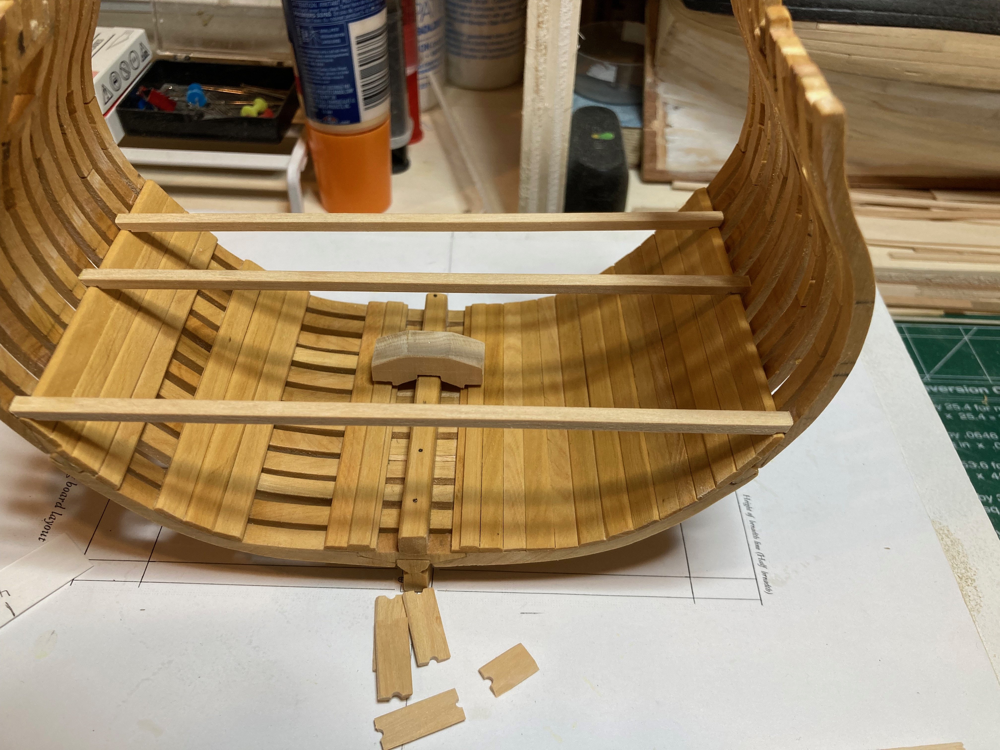
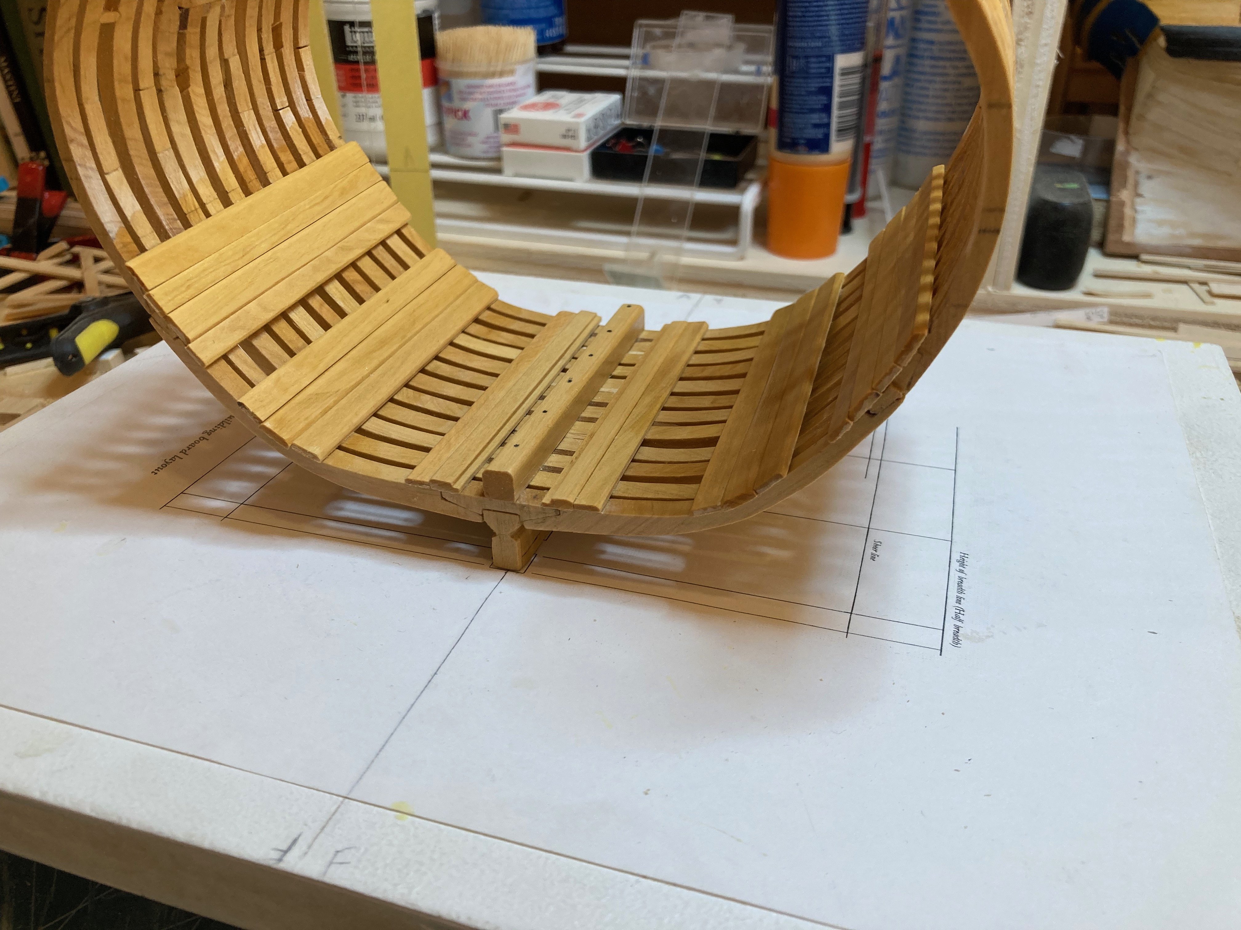
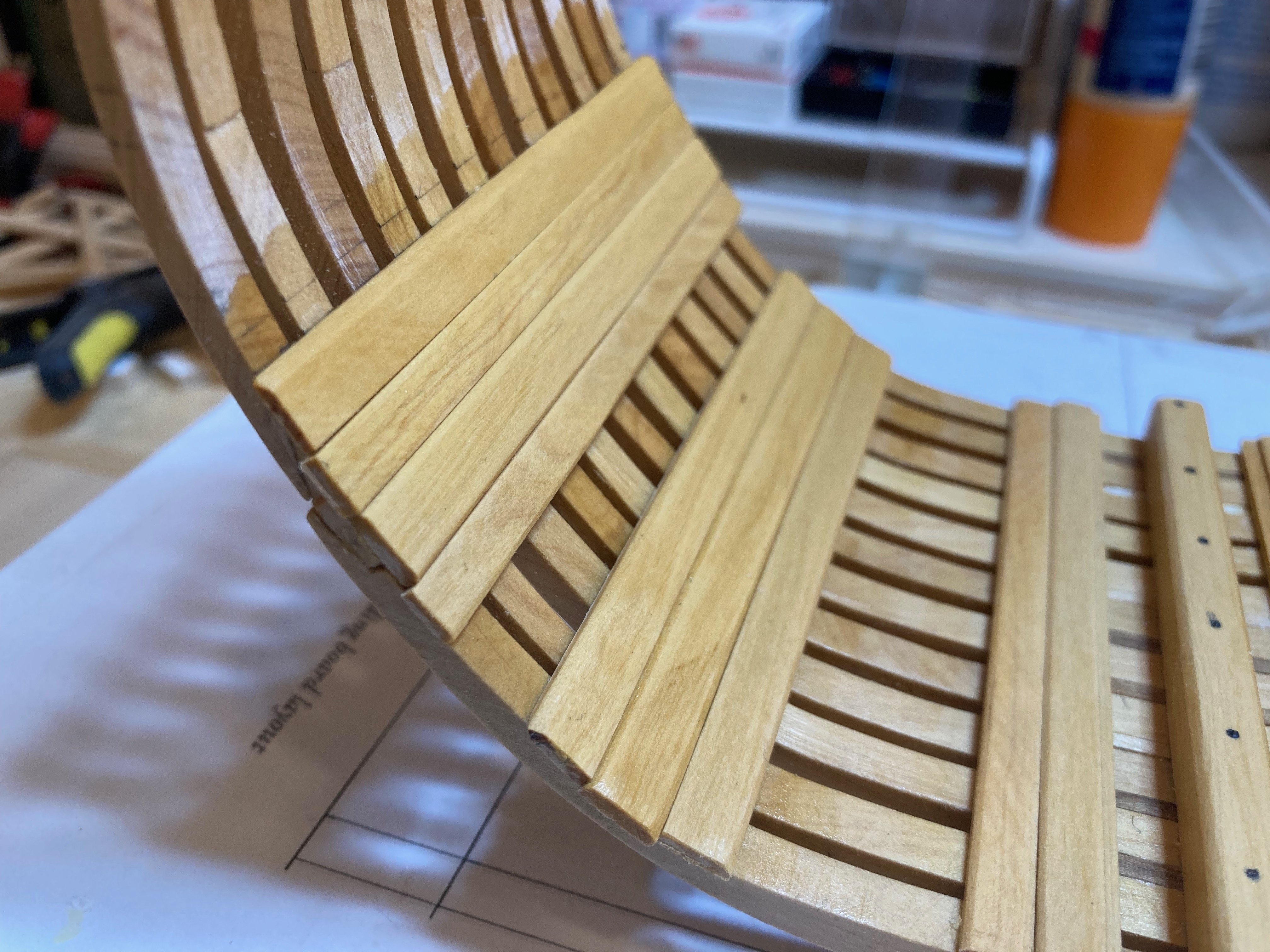
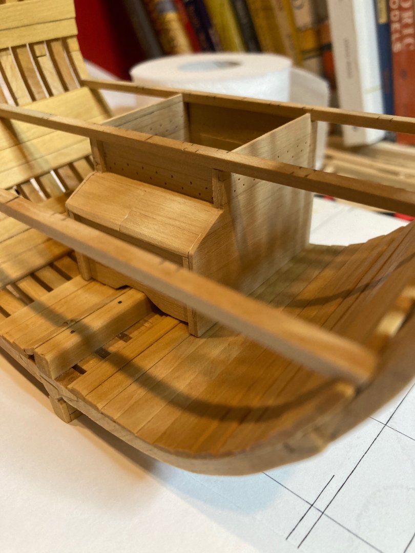
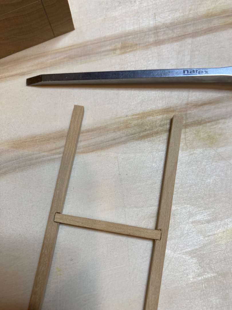
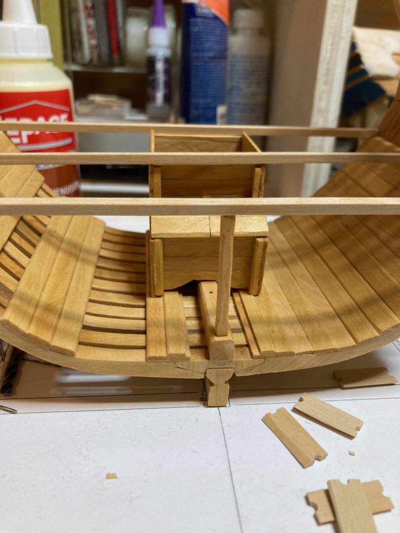
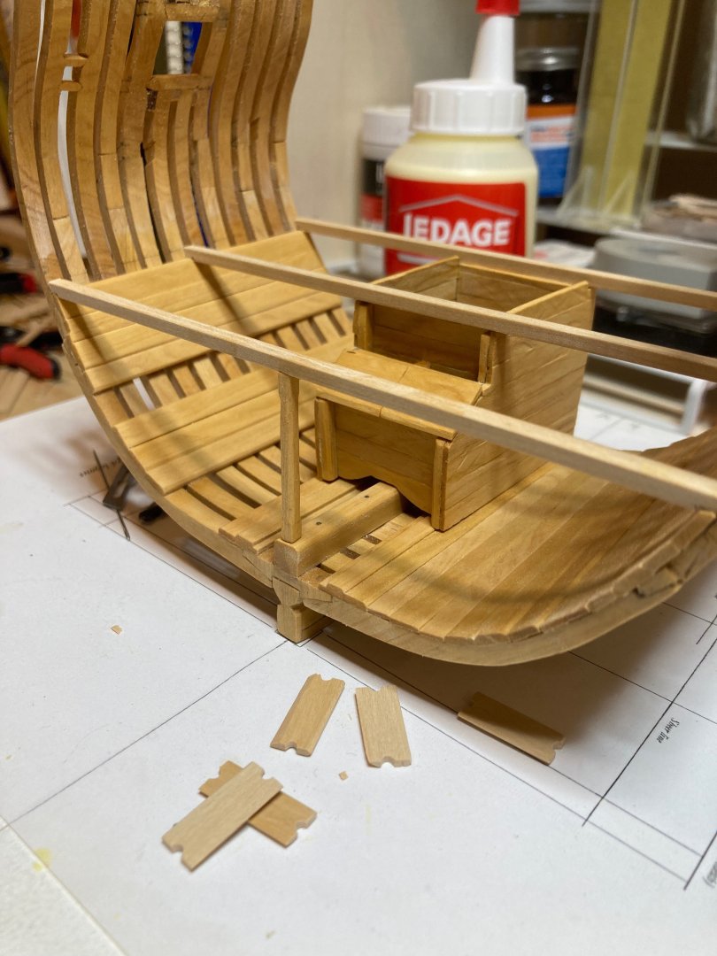
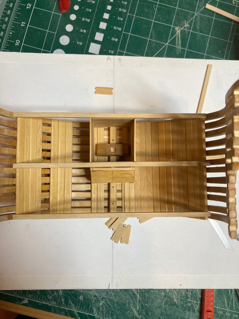
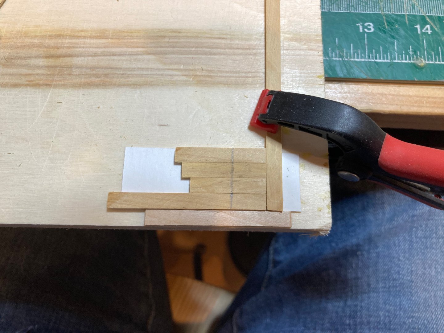
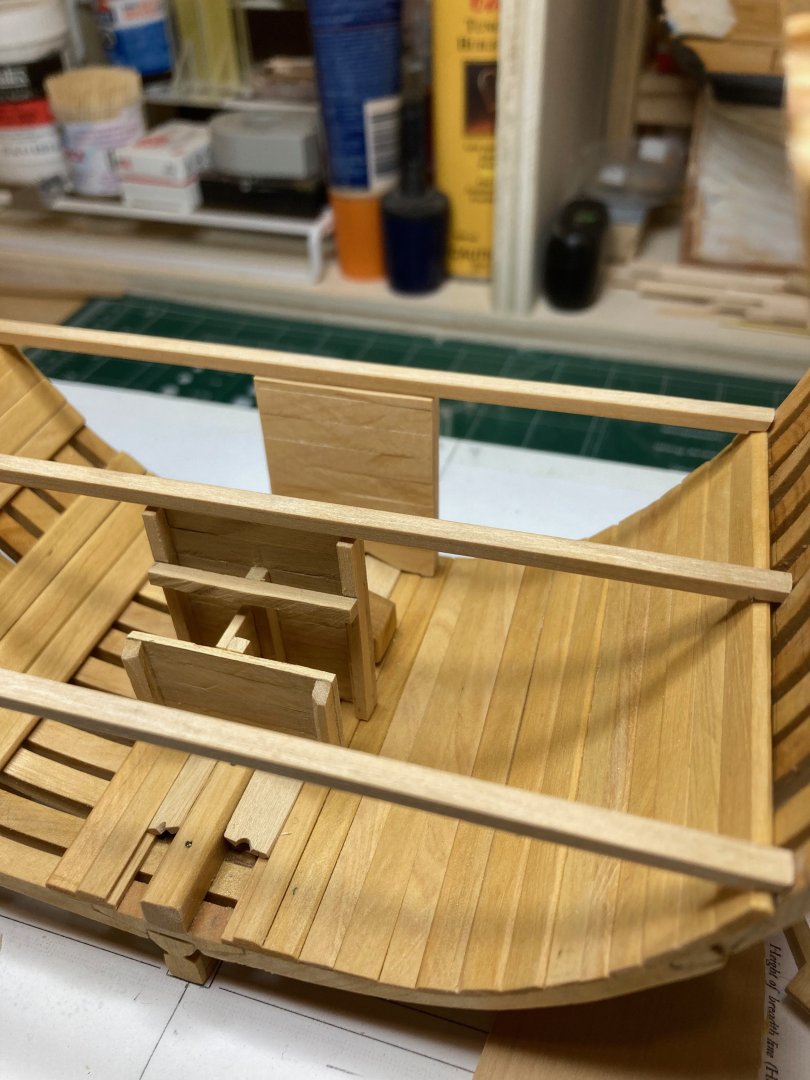
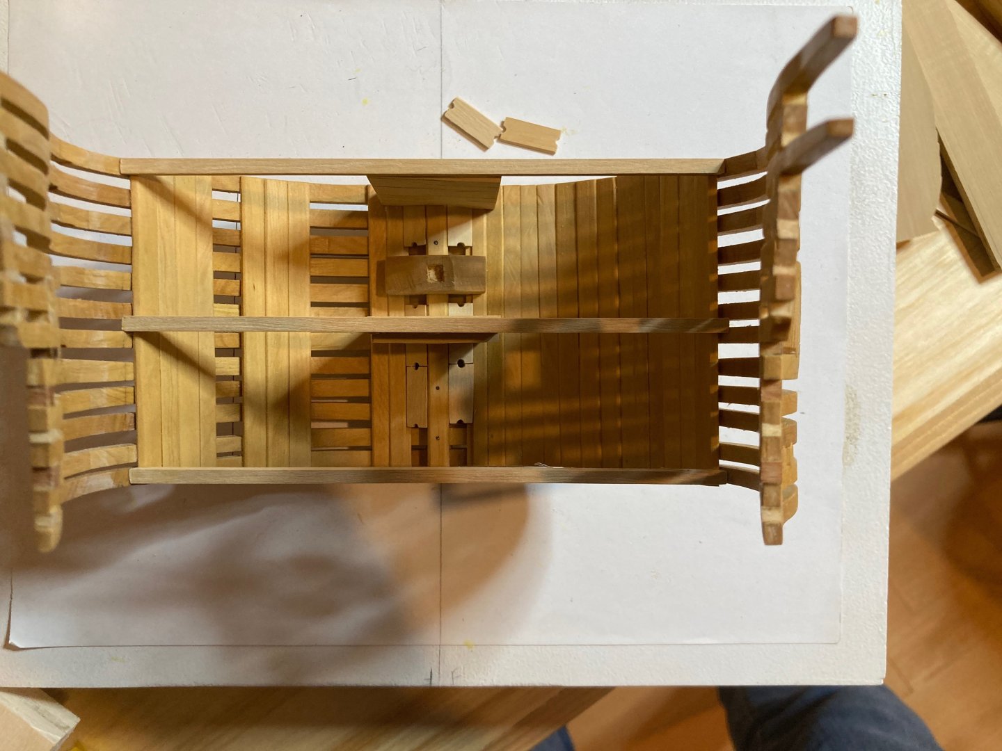
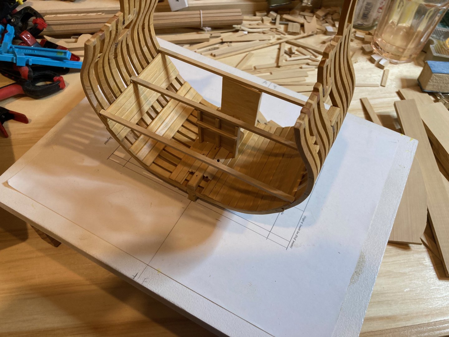
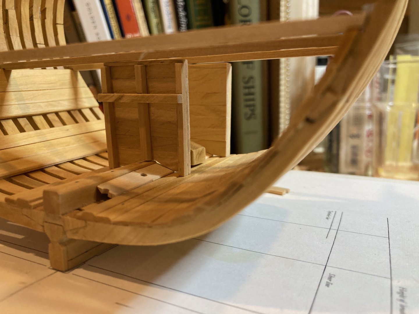
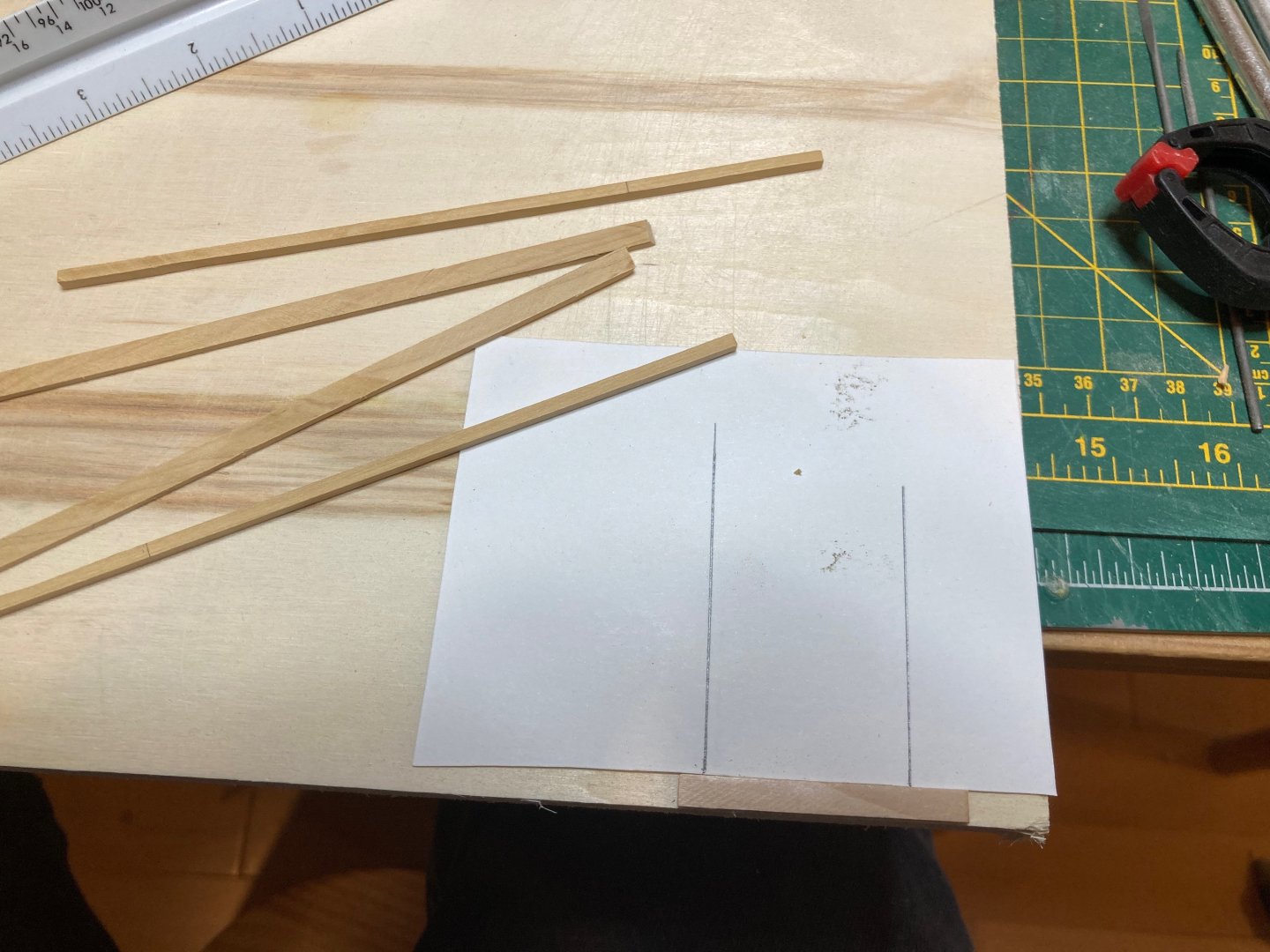
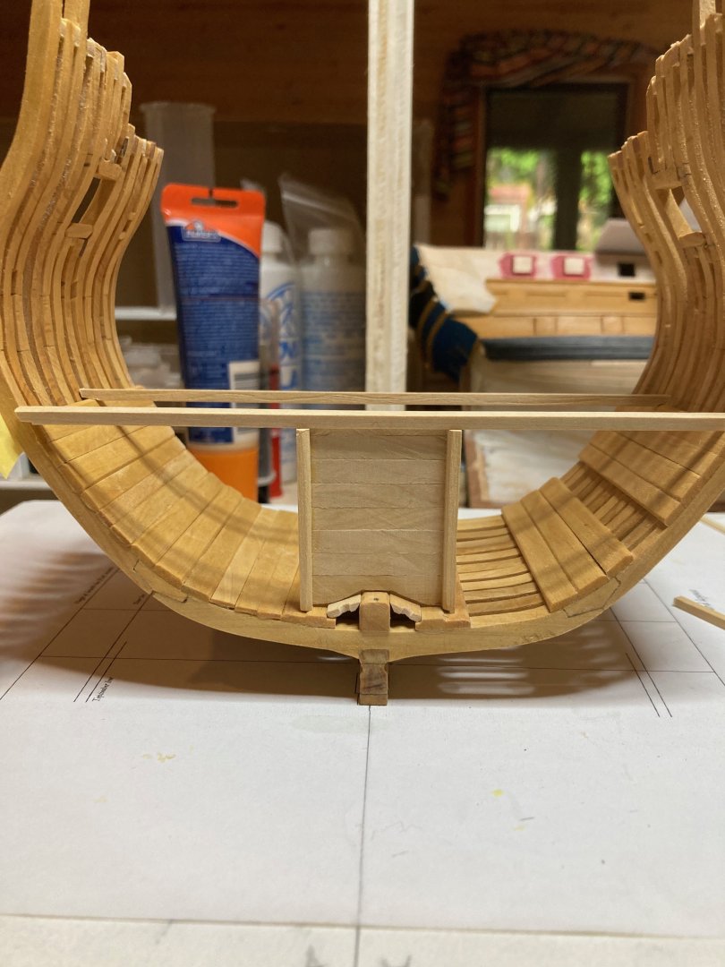
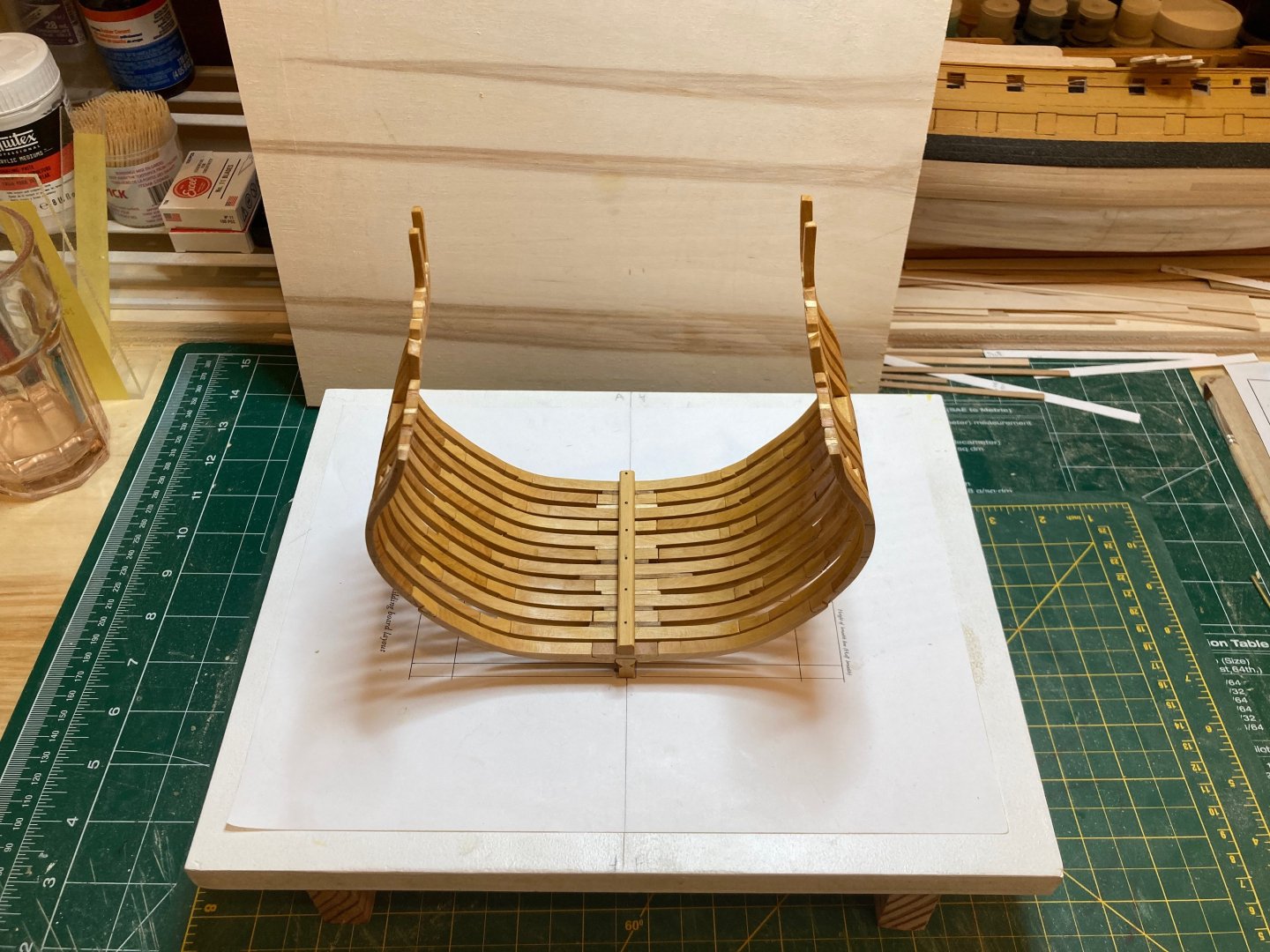
 So I did end up going ahead and building the wider well just because I was already half way through and wanted to see how it looked. It did turn out much better than the first one, just from a construction perspective, and it fits nicely below the deck pattern (everything lines up as it should). I will re-make it (a third time!) with the correct proportions, but thought I would show this version just to have it out there. Also - I did some experiments with notching out wood strips as practice for when I need to fit the carlings and ledges. I used off cuts from the lower deck deck beams and milled a few strips of 6" x 4.5" (the dimensions of the carlings. I clamped the deck beam offcuts to a piece of plywood, marked out the notch and then lightly tapped along the markings to score the wood. I then turned the piece onto its face and chiseled out the wood using a 1/8" chisel. The first experiments are ok - not a totally exact fit, but I'm not very experienced with chisels so......I have a bunch of these to cut, so I imagine I'll get used to it, but the smaller notches for the ledges will be very tricky..... Bye for now hamilton

-
So all the talk has convinced me that I should stick with the original well measurements and cheat on the pump shafts by terminating them at lower deck level, as suggested by Greg, above. This will hopefully allow me to avoid the alignment issue with the passage of the pumps through the upper deck, as noted by davec. I've already made the front and centre panels of the wider well that I had planned, so I think I will just modify these to the proper well measurements and go on from there.....I may also make some adjustments to the carlings if that helps with alignment issues.... Thanks all for the input and suggestions - it has certainly helped to clarify a path forward hamilton
-
Thanks Greg - ending the pump shafts at the lower deck is a good solution - though I wonder if, viewed from aft, the issue would turn up visually in the alignment of the shafts and the well....as mentioned above, I think I'll pursue both/all solutions until I have to commit to something. I started making a new well at wider dimensions - I'll post some photos later of the width discrepancy - it's not insignificant, though I think I've produced a cleaner and nicer-looking result. But it may look pretty daft with the extra width....and certainly not accurate! hamilton
-
Thanks for the photos Dave and Greg ! Dave - I would assume that the outline of the well would serve as a guide for the placement of the carlings, since all 4 chain pump shafts run down there. The odd thing is that all of the width measures I used - for the well, the mast partners and the slots between the carlings - were all correct, and the gauge given on the drawings in the practicum measured out at 3", indicating no distortion from printing....it is always possible that I placed the lower deck clamps incorrectly and that is throwing off the measures a bit, though I'm not sure how or if that would affect things in this way.... At this point, I'm considering two solutions - one inspired by Greg's reply above, the other by the promise of improving on the construction aspects of the well.... The first idea is to keep the pump shafts full from the lower deck planking upwards, but then notch them below the lower deck to fit the narrower slot. This would allow me to use the current well, which was built to the dimensions given in the contract. This "cheat" would not be visible on the finished model, though obviously we would all know it was there. The second idea (which I've already commenced on by not committed to) is to re-build the well at a slightly wider dimension to bring its sides out in line with the carlings above. This will be a much more noticeable change to the well's construction since it will result in a much chubbier well..... The only thing currently arguing against option 1 is that I already dismantled the original well for parts....the fore, mid and aft panels are still intact, though, so it would only be a matter of re-planking the sides, and re-doing the framing for the shot locker and the shot locker lids. Since I can pursue both options without committing to either, I think I will prepare for both and make a decision when it's time to install the well permanently - which won't be for a while in any case....glad that the speed of this hobby allows for some mulling over of problems and challenges! Thanks again Dave and Greg - very helpful!! hamilton
-
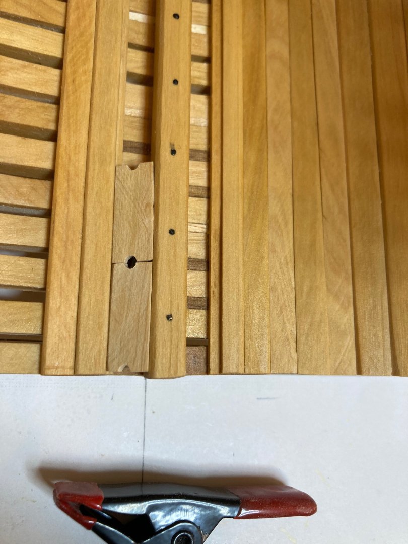
Thanks Druxey and Dave Druxey - it is the lower deck pattern, as far as I can tell - taken from page 7 of the fitting out practicum and slightly modified for the model as built. The upper deck pattern features beam arms and is pictured on pages 10 and 16. I took a tracing of the pattern on page 7 from a printout of the practicum and it was perfect in the fore and aft dimension, the deck beams falling exactly where they should. But it was short in the athwartships dimension - the centre line on the tracing fell short of the centre line on the model by about 1/8" in full scale measures - a significant discrepancy, but one which corresponds almost exactly to the gap showing between the carlings and the outboard sides of the well. The thing is, when I use my squares to check the height of beam on my model with the breadth plan adhered to the building board everything checks out - so my model is not too broad compared with the breadth drawing. The issue must have begun with some distortion in the printouts of the drawings from the practicum - either for the well, the deck pattern or (likely) both...... Dave - thanks for this - I will definitely check out your log for solutions, but I think in my case adjusting the outboard carlings towards the centre line would create too narrow a gap for the pump shafts. I guess I could push both sets of carlings inwards, but that would significantly narrow the mast partners (by a whole foot at scale!) Though it's a pain to do so, I think that redoing the well and widening it to compensate for this construction issue is the easiest option....I wonder if it'll end up looking a bit too plump.......it's not an insignificant change to the dimensions....but I honestly don't see any other way to address the problem at this point.....at least building the well was fun....I can probably do better with it the second time around...insert other affirmative/ encouraging statements here..... finally - should the sides of the well be aligned with the outboard carlings that define the space for the pump shafts? I'm going to try to re-make the well so that the inboard edge of the carling is in line with the inside face of the sides of the well.... hamiltond
-
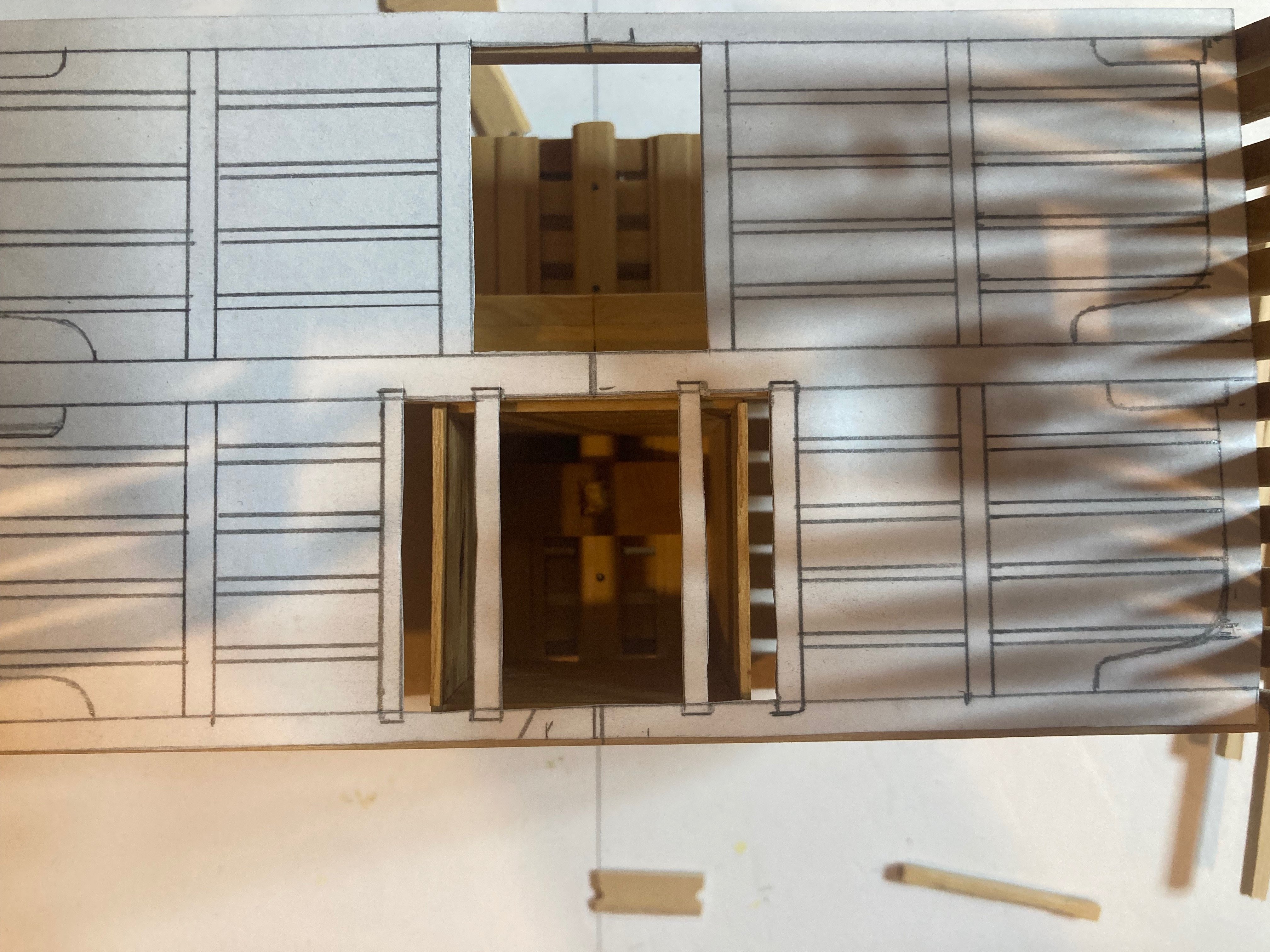
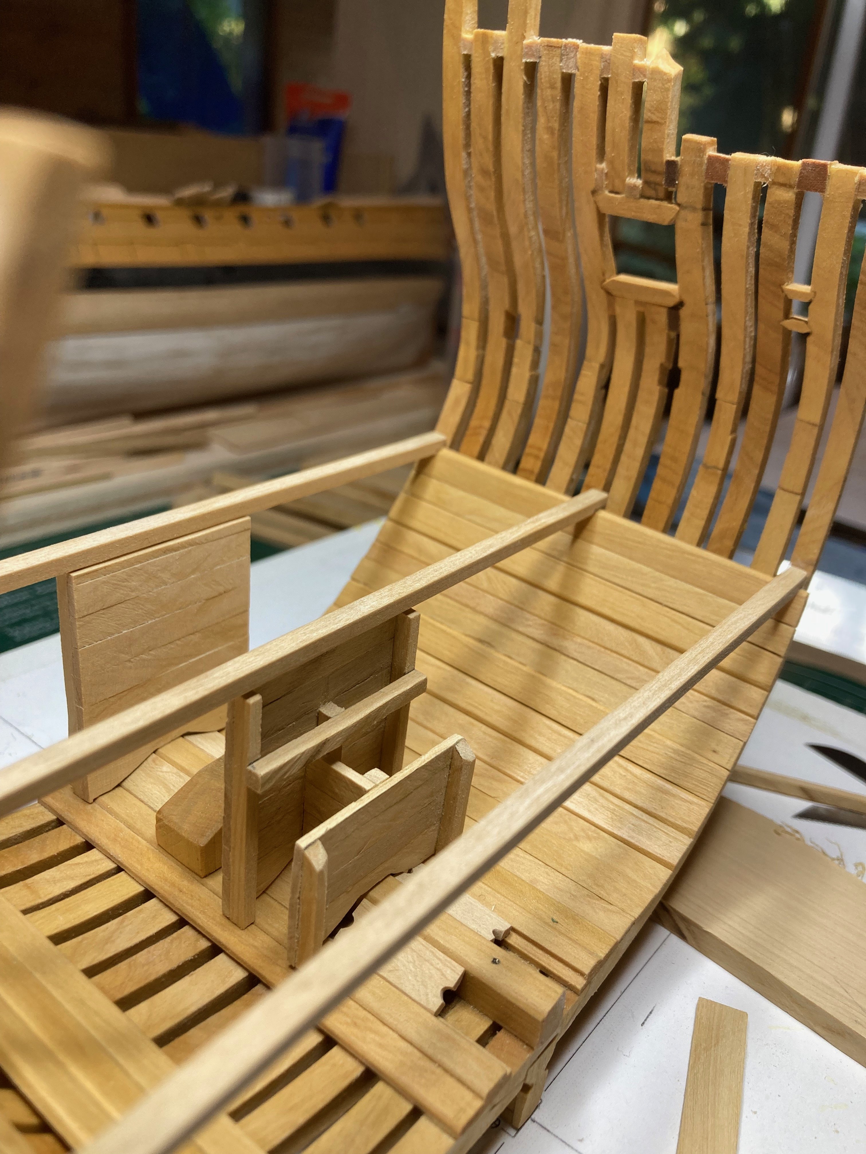
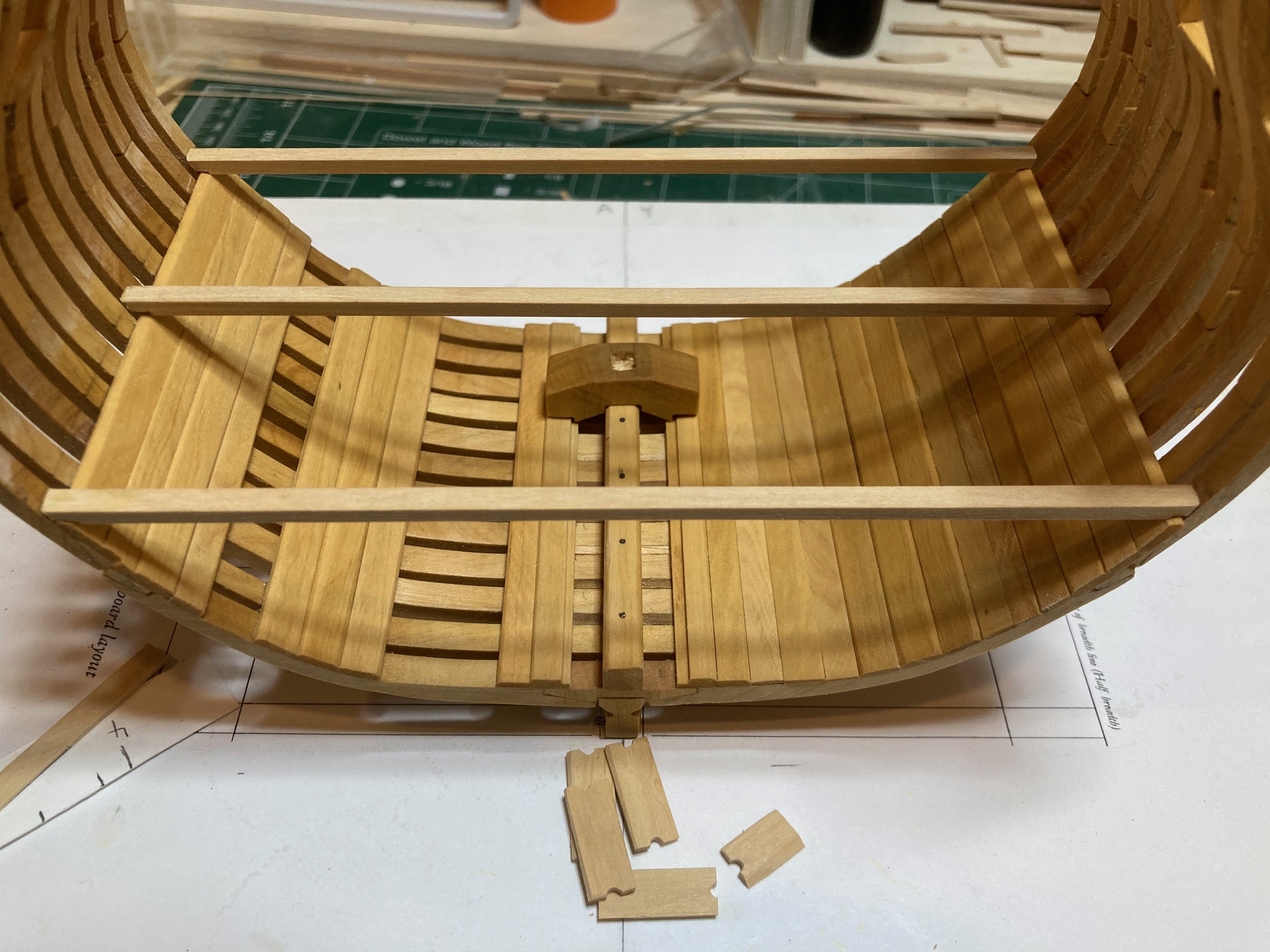
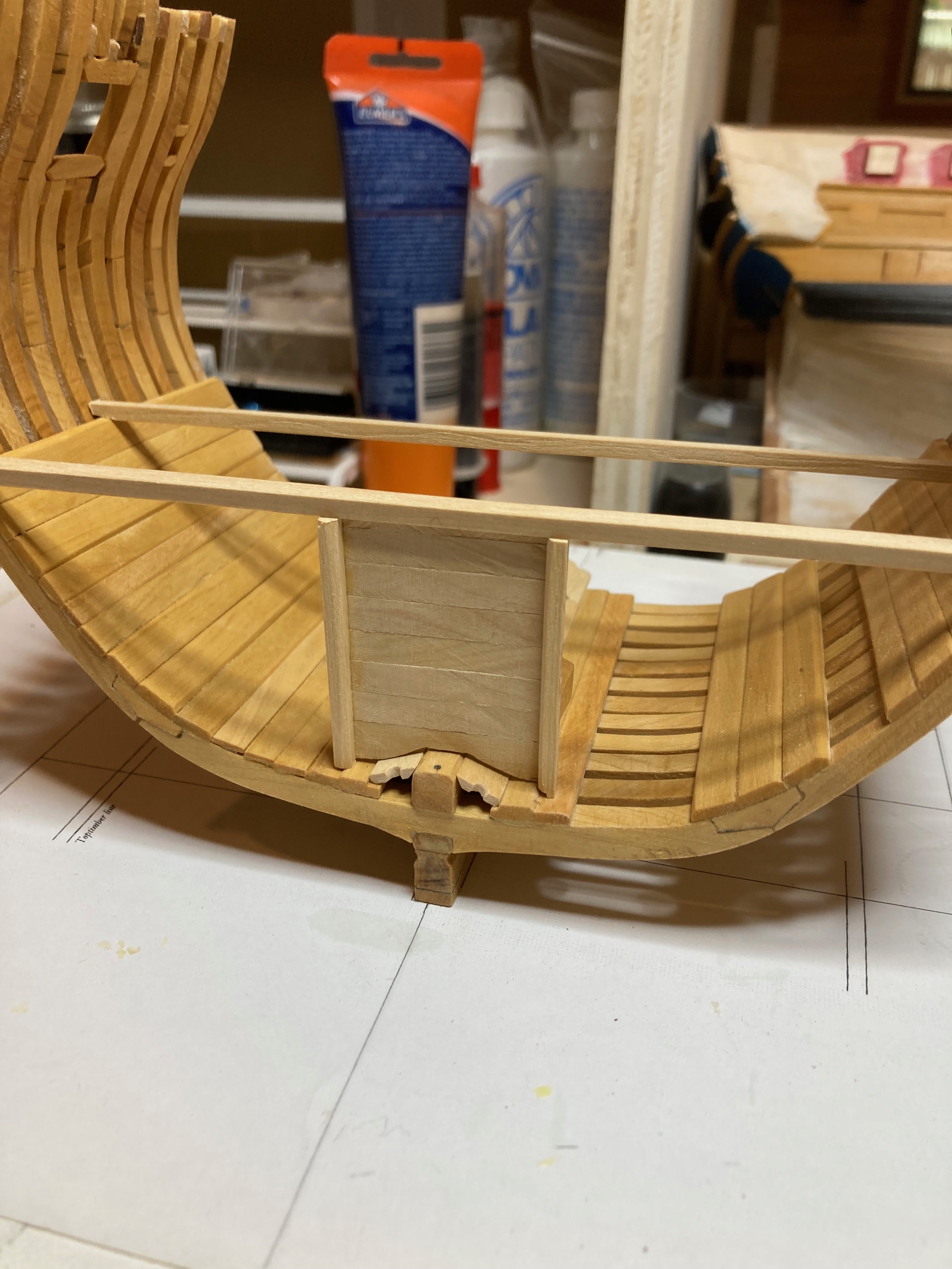
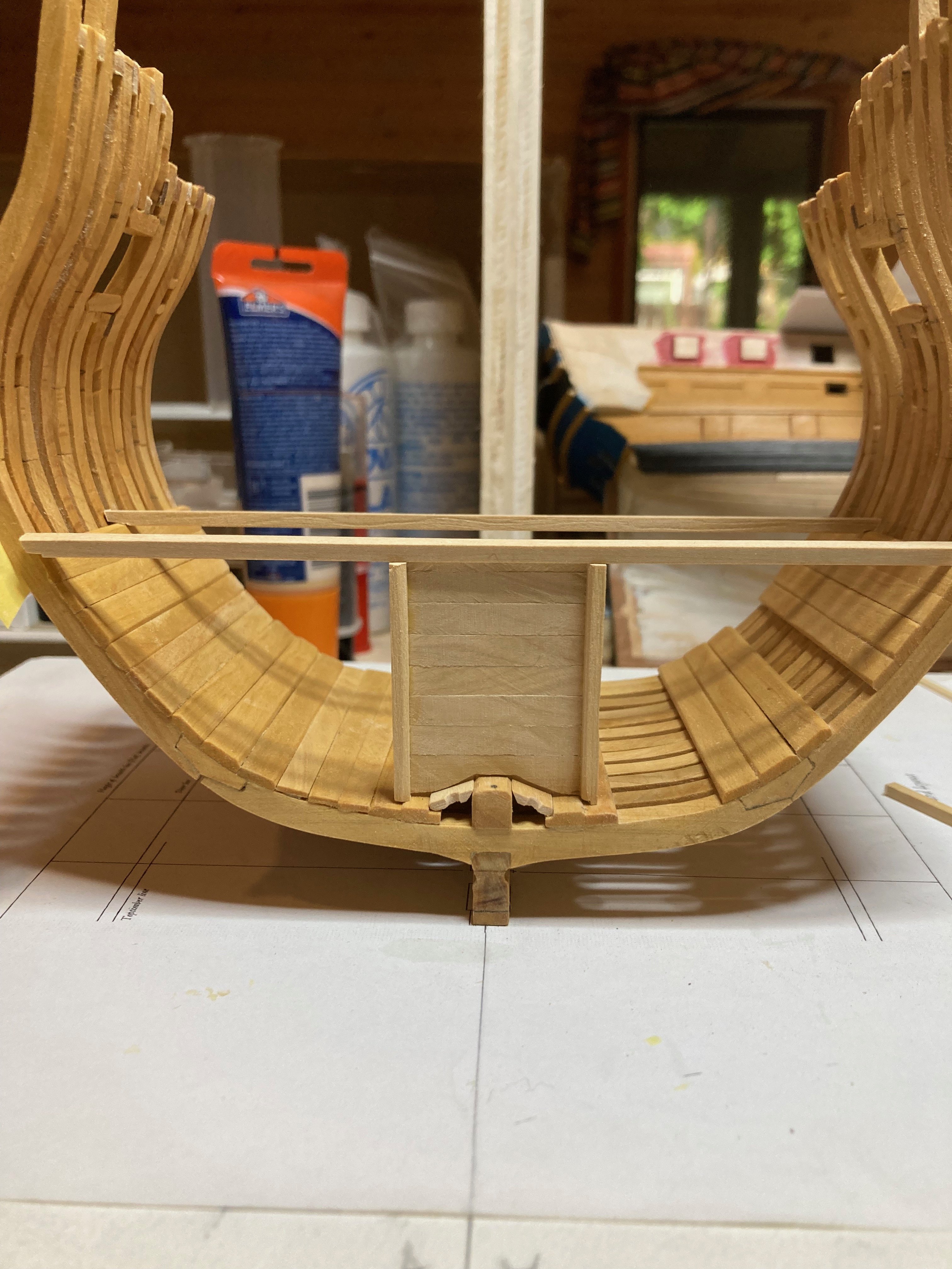
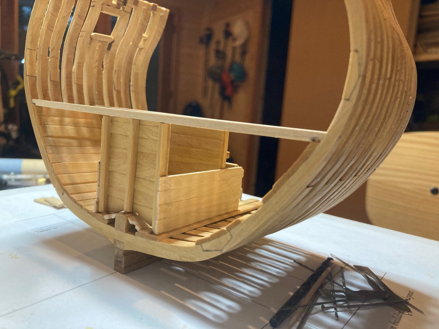
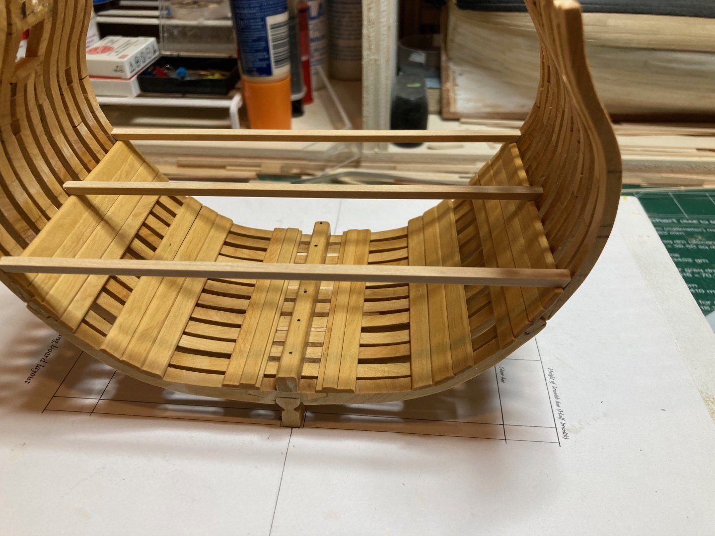
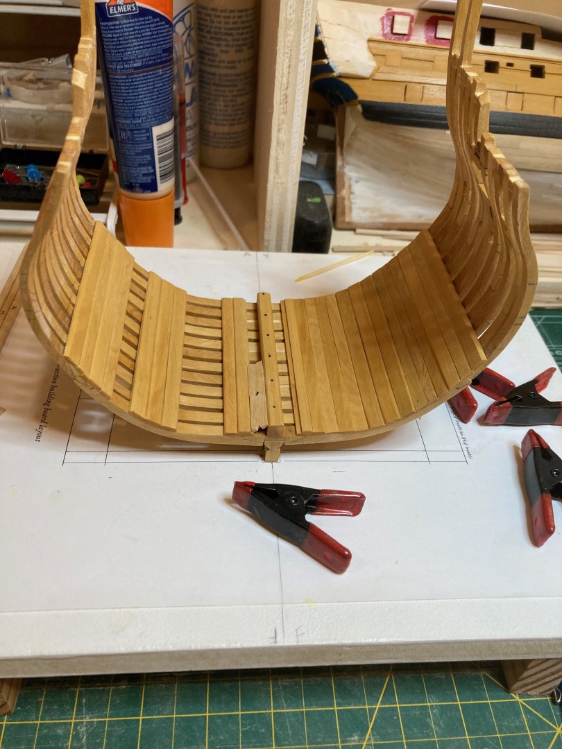
OK - I've hit a snag....the photo below shows the issue..... I cut away those sections of the deck framing template that define the space for the hatch, the mast partners and the spaces on either side of the partners for the pump shafts. But when I fit the template back onto the deck beams on the model, I found that the sides of the well run through the middle of the spaces for the pump shafts....I know that the space for the mast partners is correct because I took the measure from the practicum. And I know that the pump shaft slots are correct in their width because they match the 1:48 drawing in the practicum and my printout of this drawing is not distorted per the measures provided.... So I guess I have to reconstruct the well to widen it. My question is - should the port and starboard sides of the well sit underneath the outboard carlings for the pump shaft slots? My instinct is to re-make it to those athwartship dimensions, but I'm unclear whether this is how it should be done - clearly the way it is now is not the way it should be done..... Any pointers will be greatly appreciated!! Thanks and bye for now hamilton

-
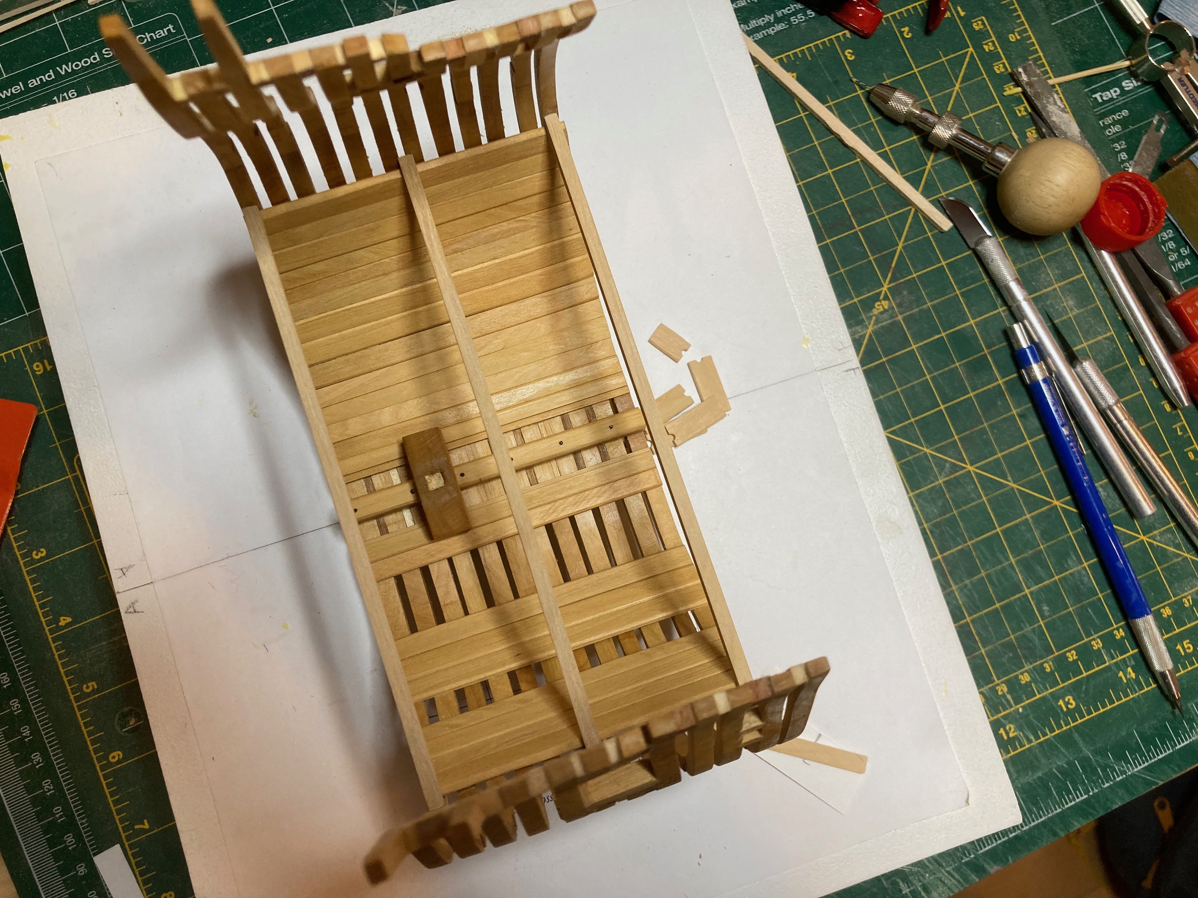
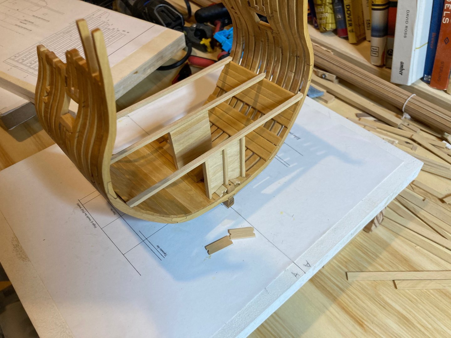
Work is definitely slowing now - first because of the rising demands of work, which will only mount from now until Christmas, and second because there are some key processes that I'm unsure how to effect - at this stage this is primarily the notching of the deck beams for the carlings (and the carlings for the ledges). The carlings are 6" wide and the ledges are 3 1/2" wide (1/8" and 5/64", respectively, at scale). I've just invested in a 1/8" chisel, so theoretically the notches on the beams for the carlings can be done, but how to cleanly cut out a 3 1/2" notch is driving me to distraction....I had thought of using the drill press with an appropriately sized bit to cut out an initial section that could then be squared off, but if there are other methods out there, I would love to hear about them - it's always nice to have options! In the meantime, I made a template for the deck framing and can now proceed with fabricating the basic elements - carlings, ledges and the hanging and lodging knees. You'll note in the photo below that the centre line diverges from itself from fore to aft - this has been corrected, but I don't have ohoto documentation of that..... There is only one image of the lower deck hanging knees in the practicum and there is no indication of whether the drawing is in scale or not, though dimensions of both the beam and hanging arms are provided. I will use these as starting points and work the knees up to fit the model as built. I noted the positions of the carlings on the deck beams using the template and then milled some wood for the upper deck clamps, which need to be tapered across their width prior to installation. I also made the pillar in the hold - the last of those elements to be made prior to lower deck framing. I'm still a little cloudy on the build order here - I need to prepare the deck beams before installing them, but then I assume it's best to permanently install the deck means along with the mast step, limber boards, well, and pillar and then add the other deck framing elements from there.....though again - if there is another way (or one that those more experienced than me have) I would be interested in hearing it. That's all for now - just a couple of photos for now.... hamilton

-
Wow - really nice work on the companionway and other deck features, Cisco! Clean and precise! hamilton
-
The well/shot locker is now done apart from the hardware for the shot locker lids, which will be a challenge for me given my lack of experience with metal work....in any case the work is not perfect, but that's ok with me - learning as I go and hopefully the results will be better next time...in any case I'm happy with the results, such as they are. Everything is still dry fit, so it's tricky to get things absolutely lined up, but you get the idea. After the hardware for the shot locker lids (or before depending on how well my experiments go), I'll move on to the pillar in the hold and will then install all these elements permanently. Before installing the lower deck beams, I'll have to mark them and notch them out for the carlings - for this a framing template needs to be made from the deck plan included in the practicum, adjusted for the model as built, and a centreline marked on the deck beams. And on, and on.... hamilton


-
"A+" Giampiero! Unfortunately I'm in no mood or position to correct this, so will simply continue learning from useful comments such as yours...nice work on Pegasus, btw. hamilton
-
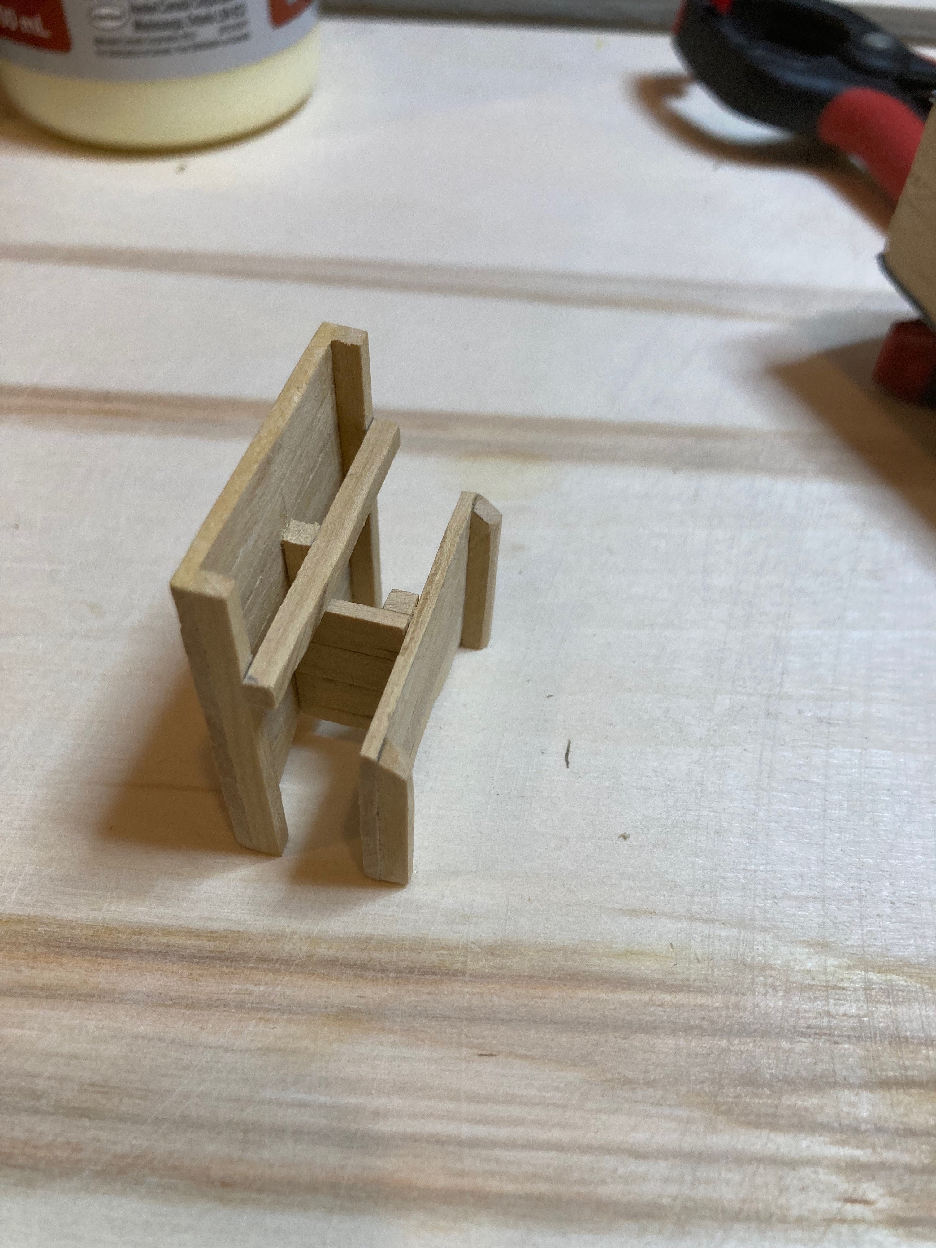
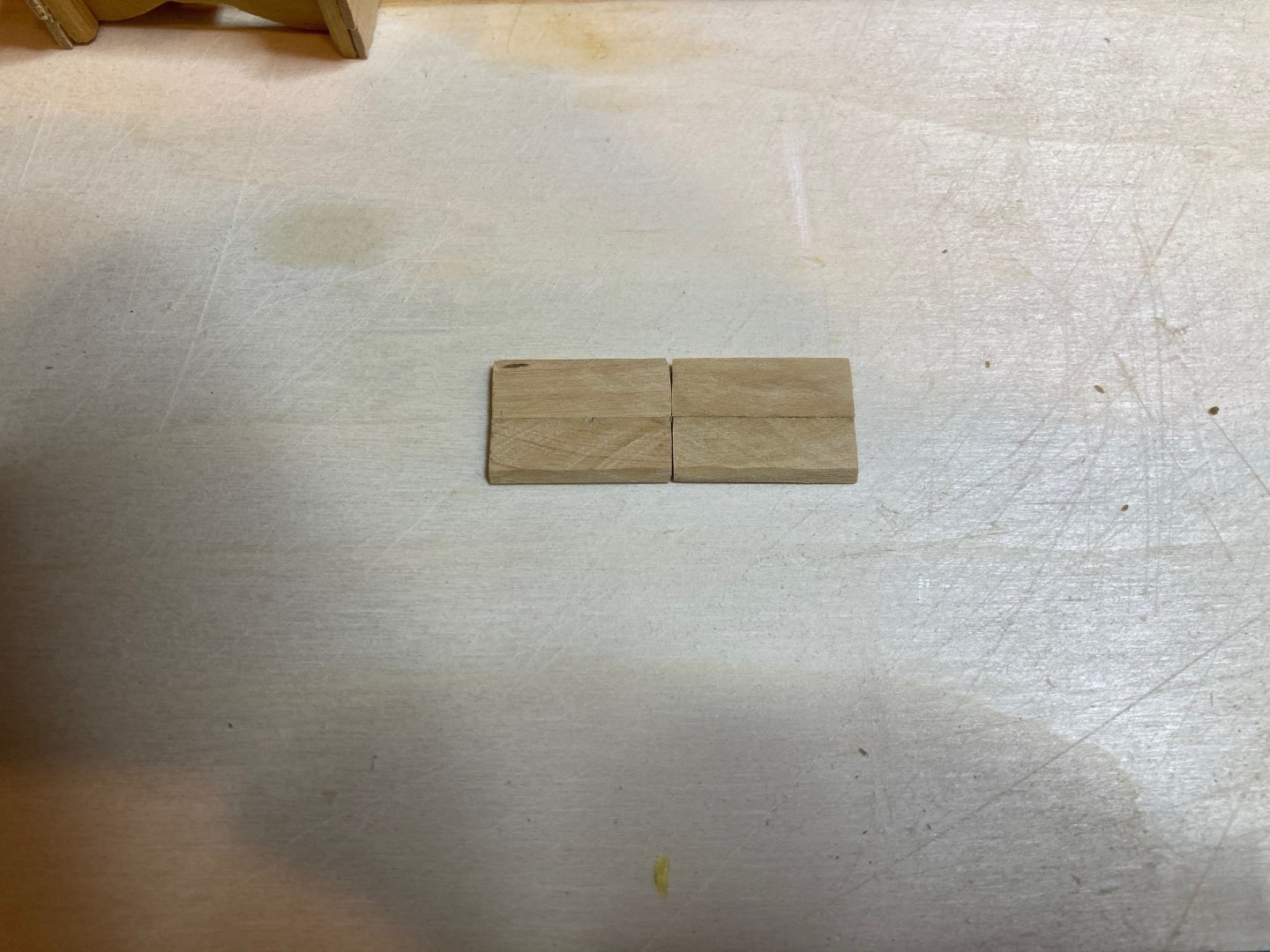
Thanks Druxey! Means a lot coming from you! Work continues on the well. Today I managed to make the forward panel of the well, which is actually the forward panel of the shot locker. I also made a small interior panel that separates the port and starboard sections of the shot locker. To do this, I made a small right angle jig and edge glued the pieces together before attaching a 4" x 4" stanchion to one edge - the other is fixed to the corresponding centre stanchion on the middle panel. Photos below. Once the three panels were complete and the middle one attached to the forward one, I dry fit the panels onto the model in its proper position - this allowed me to run a tick strip alongside the panels and take a measure of its overall length. I then made a small "cradle" - really just some 1/16" basswood strips clamped onto a piece of plywood - to the well's length measure. The fore and mid panel stand on their own, while I used a couple of clamps to keep the aft panel upright while the first planks were installed. Photos also below. I only planked as far as where the planks start to angle back to accommodate the shot locker lids. I then made the shot locker lids using 14" boxwood milled to 2". Two stripe were used for each of the lids, edge glued together. The top and bottom ends were chamfered off to fit snugly in place - they are not yet attached to the model but I am using them to cut the planking strips of the well that angle back in line with them....the work week starts again, but I may be able to carve out time evenings this week, so hopefully a bit more progress - hard to believe that another school year is about to start - they are going by faster every time - I might have liked that a decade ago, now, I'm not so sure.... hamilton


-
Loving your work on this Mike! How do you keep your model so clean? hamilton
-
Thanks for stopping in Brian! Yes, it does look that way - definitely not just you. But the parts are currently dry fit - it;s actually very tricky to set the parts up at this point and haven them sit nicely - this was the best I could get with my more or less steady-ish hands....when I do the final assembly of the well, I will definitely ensure that it is square and sits properly in its place! No one likes an unruly well!! hamilton
-
Made the middle panel of the well today - same procedure as the aft panel with one added element - a 4" x 4" cross piece that defines the top of the shot locker and on which the hinges for the shot locker lids sit. This middle panel tenons into the central lower deck beam. The photos below show the parts dry fit on the cross-section. Next up is the front panel of the shot locker, after which the port and starboard side cladding can be put on to complete the basic form of the well. The shot locker lids and hardware will finish this off - I will try to make the hinges, etc, from brass, but my metal working skills are pretty much non-existent....a real impediment for scratch building....we'll see how it goes.... In the meantime enjoy the photos and bye for now hamilton


-
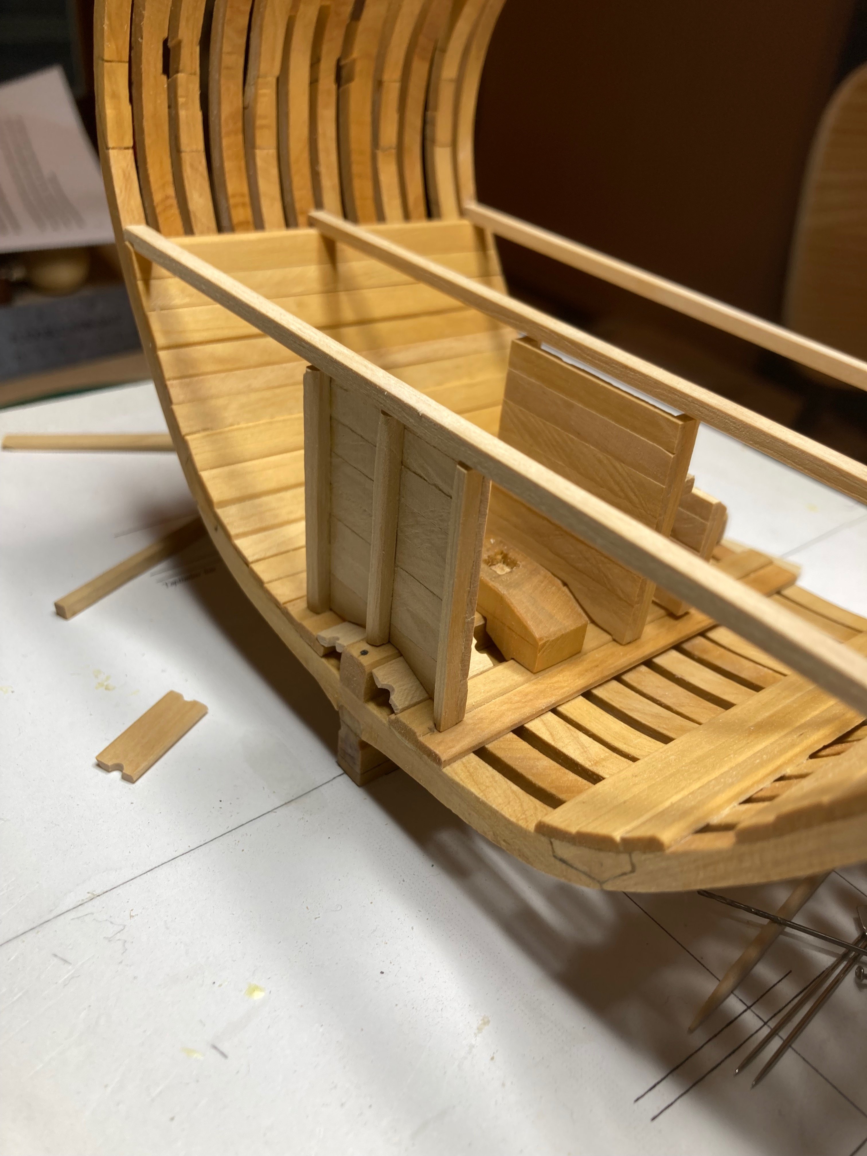
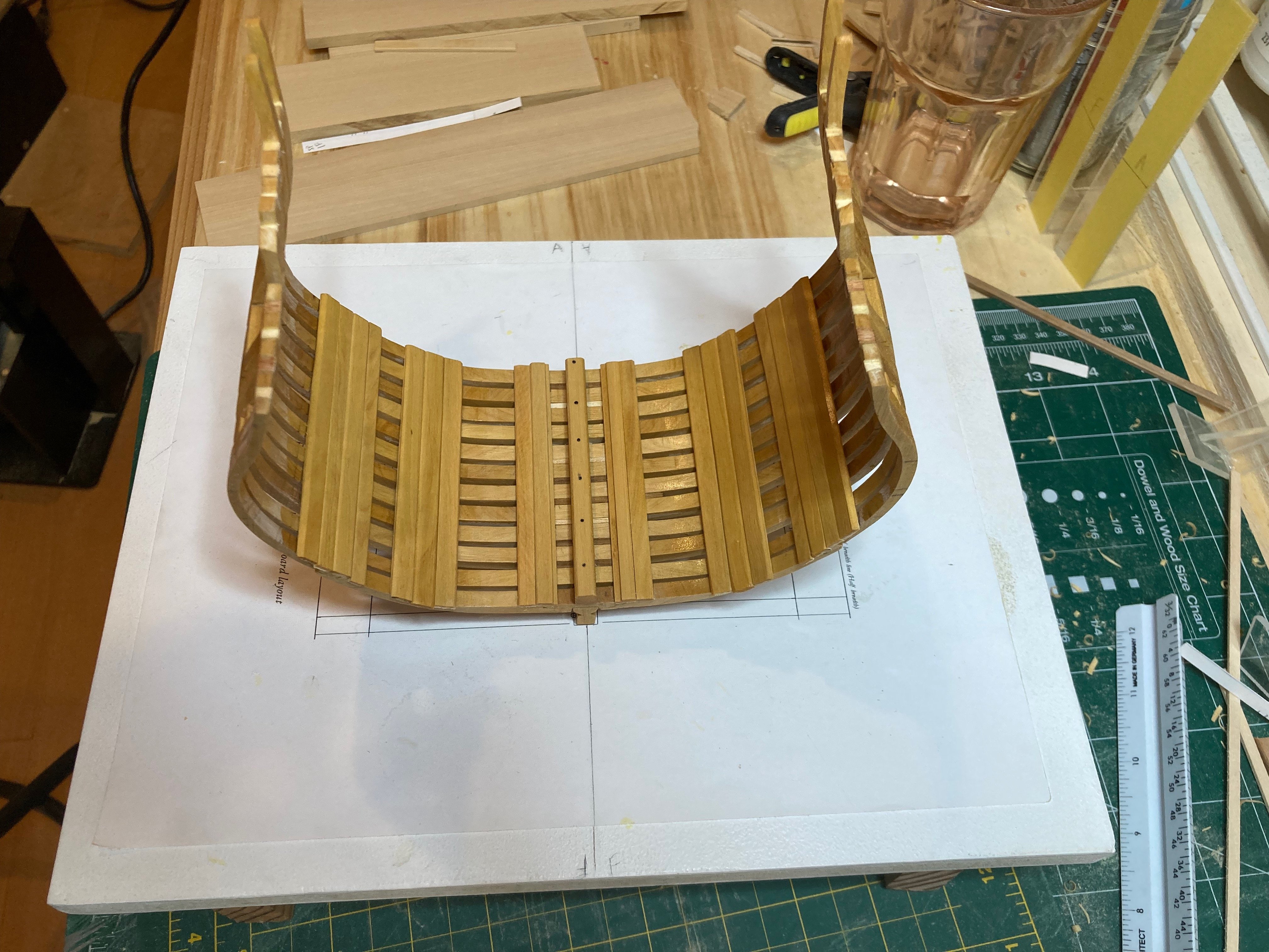
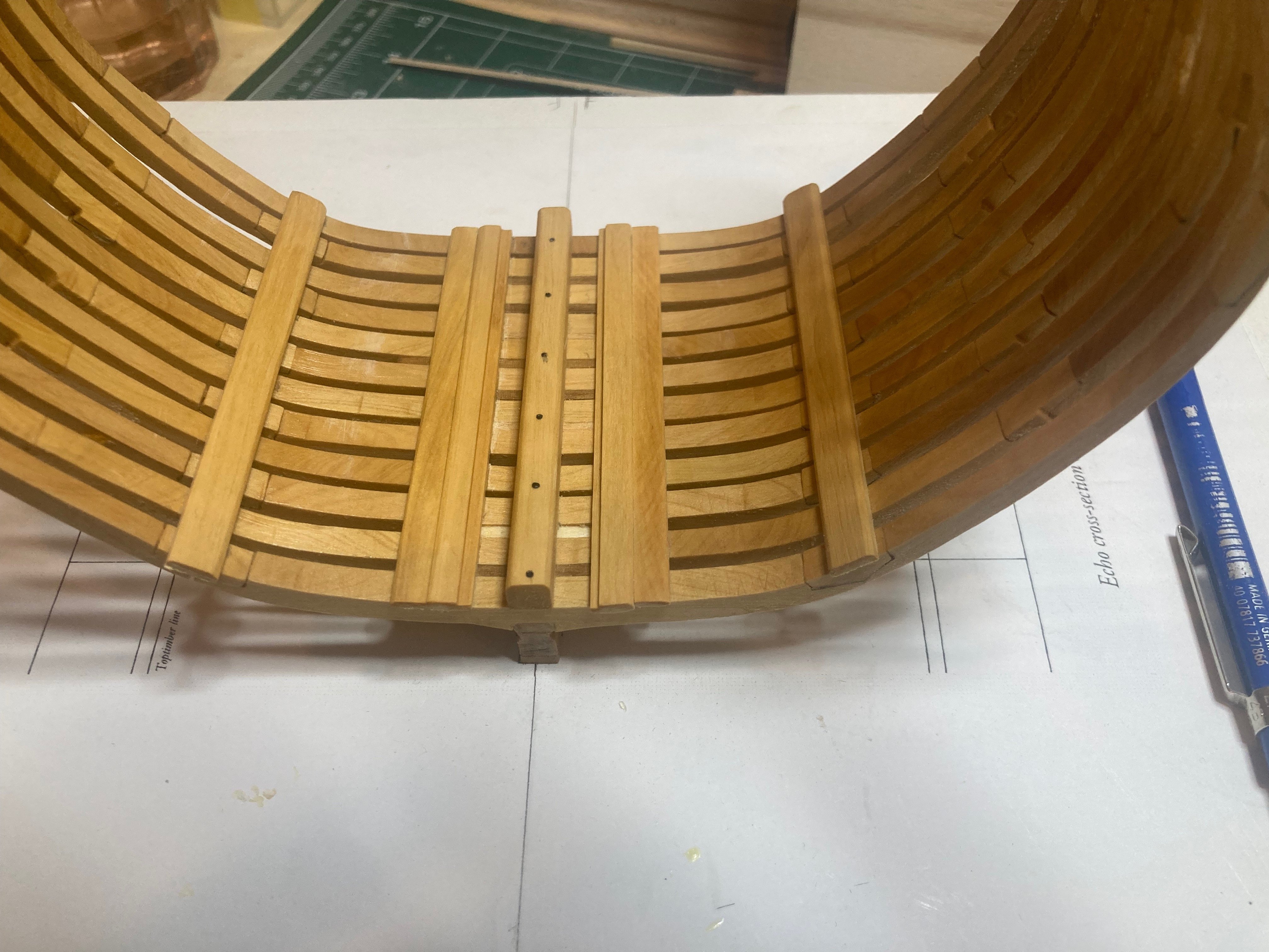
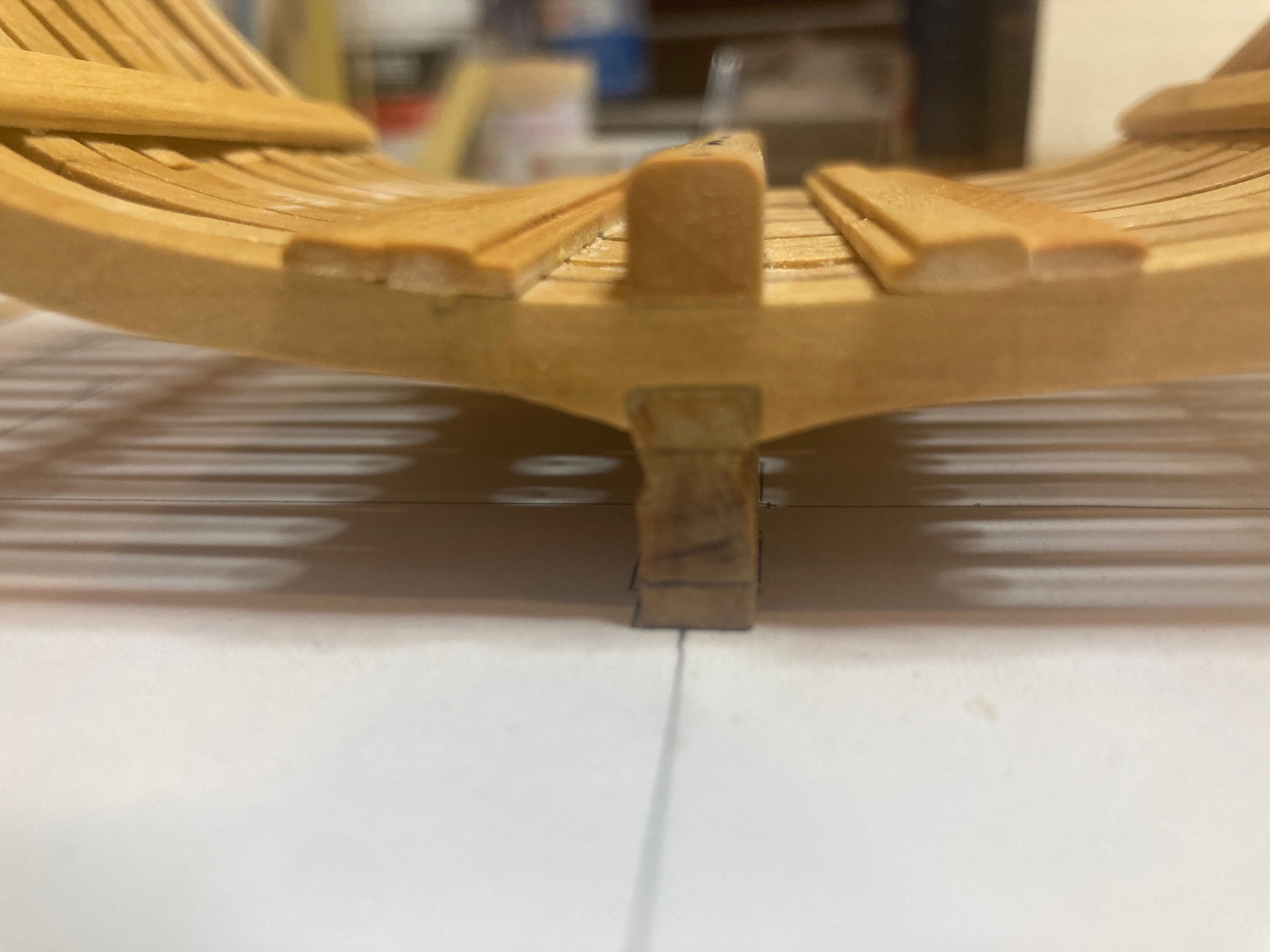
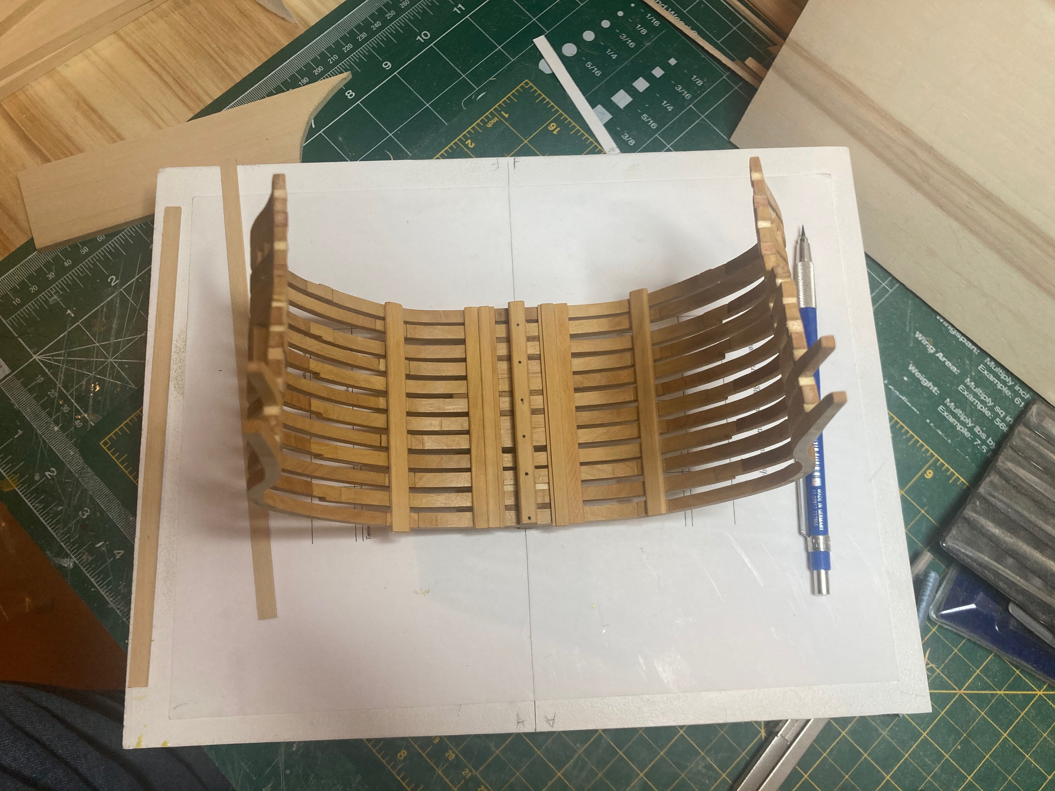
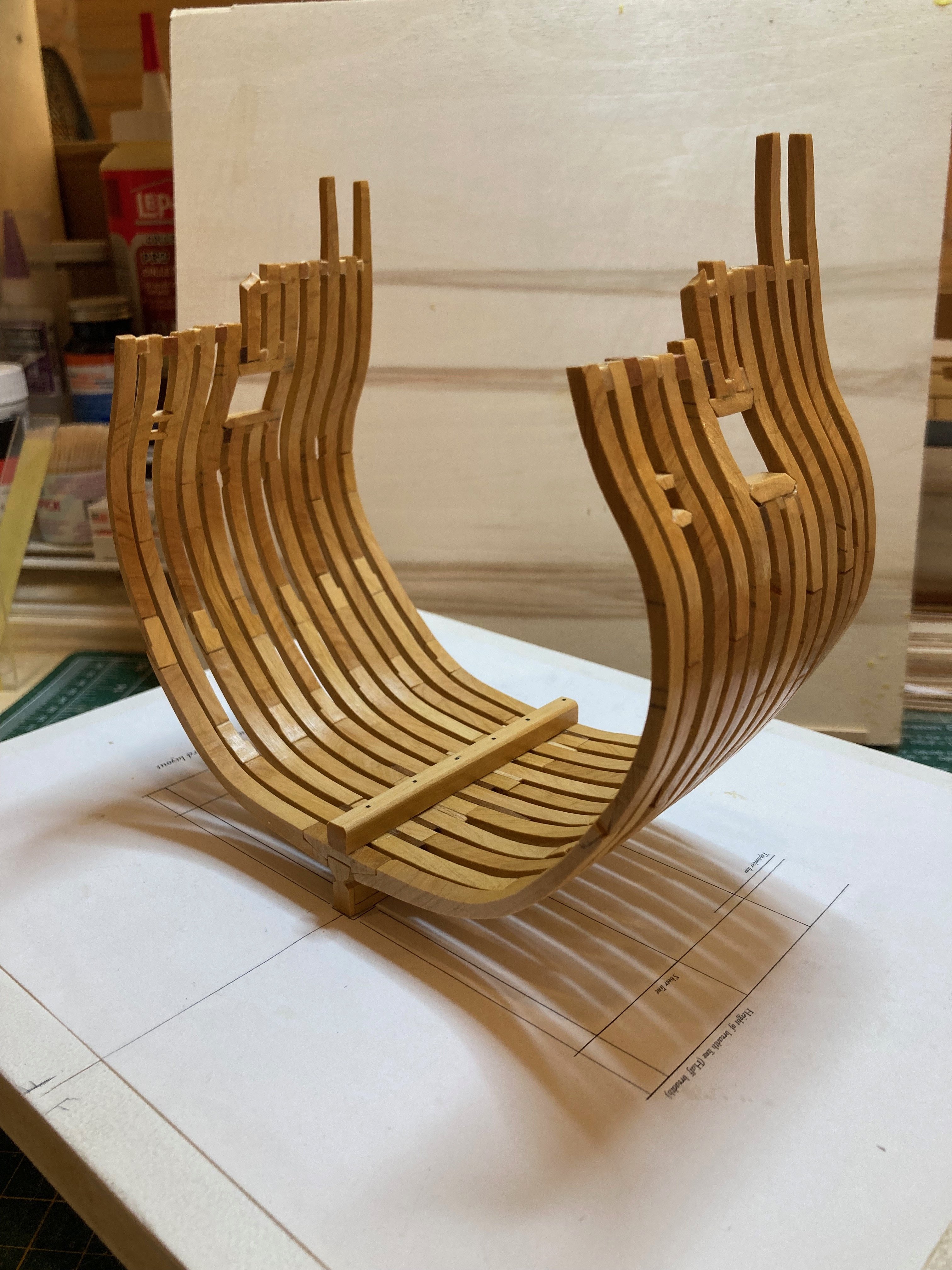
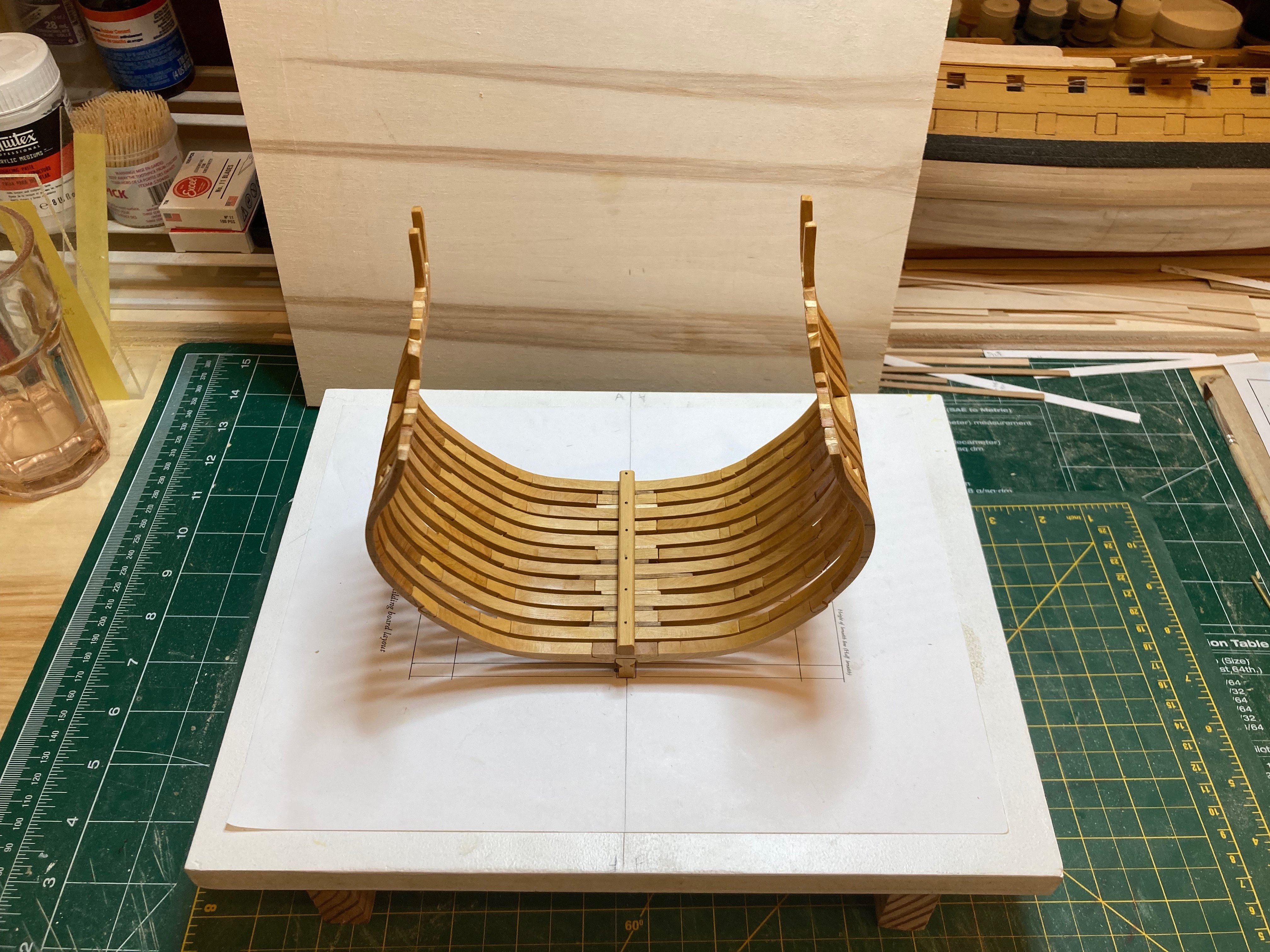
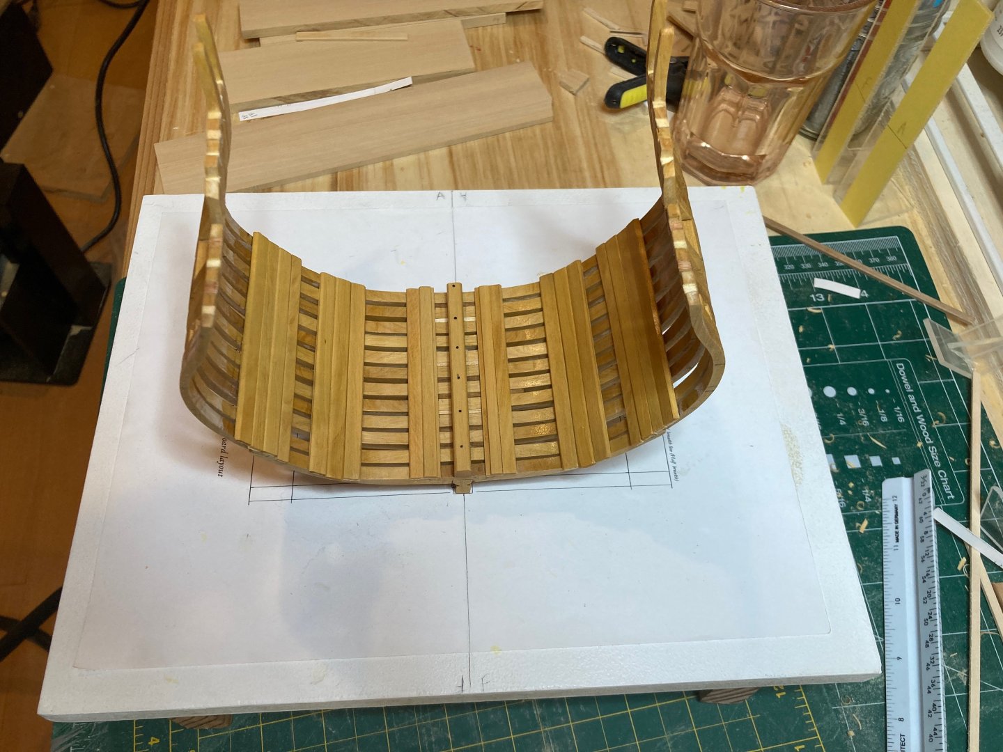
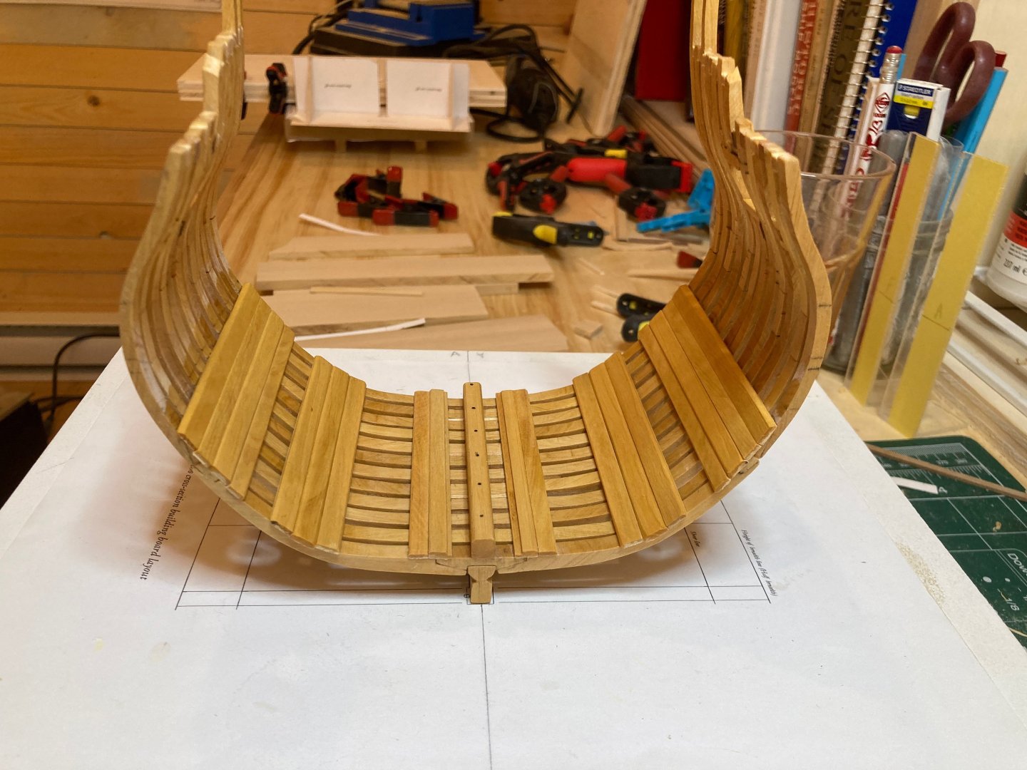
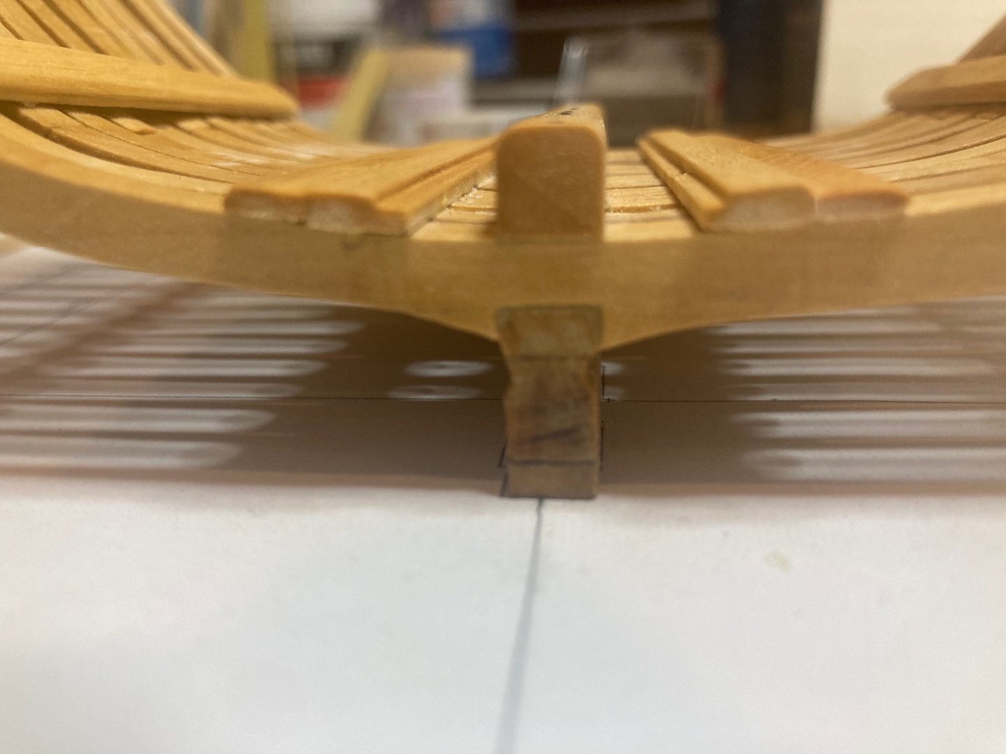
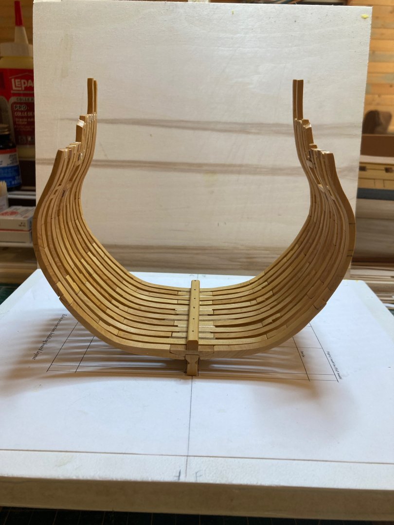
A bit more progress to report on Echo. At this point, I will be making a lot of items and not installing them yet - I've reached the stage where I need to start thinking about how the structural elements (mast step, deck framing, mast partners) align to support the interior fixtures (well, pump shafts, bitt pins). So what you see below is all dry fit for now - in some instances a bit sloppily - till such a time as sets of elements (e.g., well, mast step, deck beams and pillar in the hold) can be installed together. Today I cut the square mortice into the mast step, finished it with wipe-on poly and finished cutting and shaping the limber boards - because of a slight asymmetry in the milling of the groove in the limber boards, I had to make one set of limber boards 15" wide and the other about 15.5" - not a huge discrepancy but a little noticeable on close inspection. I also started on the well, making the aftmost panel, which tenons into the deck beam above and into the limber boards below. To make this, I took an athwartships measurement of the well from the plans and marked two lines on a piece of card paper that represented the outboard edges of the port and starboard stanchions of the well. I had a small strip of basswood glued to a slab of 3/4" ply and placed the card template against this - I could then take the 4" x 4" boxwood strips I milled put them against this stopper and aligned with the markings on the template. I clamped the boxwood stanchions and then milled some 2" x 10" planks to use as cladding. Cutting away the bottom plank to fit around the keelson and limber boards, etc. was pretty tricky. Once again, I made a template by laying a piece of card along the aft adge of the cross section and tracing the outline of the keelson, limber boards and limber strakes and cutting the card to this tracing. Quite a lot of little adjustments were needed until it fit reasonably well and I could transfer it to the wood strip (an extra wide one of about 12") at the bottom of the well panel. I rough cut the wood on the scroll saw and then finished with a flat needle file. It does not fit perfectly, but I think the results are ok for a first effort..... I'll be finishing up the well over the weekend hopefully and if there's time I'll make the pillar that supports the forwardmost deck beam - I'll then be able to get started on the deck framing I guess....that's what's up in the practicum anyway - I'll have to try to puzzle out how to get the vertical alignments for the mast step/partners, pump shatfs, etc. - for this it seems necessary to get into the framing of both lower and upper decks at the same time.... In the meantime, enjoy the photos and happy modelling. hamiltin


-
Yes - I have to say that working with boxwood is a dream after so long working with basswood.....finishes so nicely and easy to maintain edges...makes up for many of my skill deficiencies! hamilton
-
Work is back on pretty fully so these days if I can carve out 30 mins or so before dinner I feel lucky....I've made a bit of progress since the last post, as follows: 1. Foot waling - installed on port side only to show frames to starboard - very straightforward to custom make these 2" thick planks using billets made for the thick stuff, deck clamps and limber boards - the mini table saw and thickness sander are really crucial to this process. 2. Lower deck beams - I mentioned that I had rough cut these the other day, but today I notched them to let down by 1" onto the deck clamps - also not difficult. These are not installed until the well and support post are completed. 3. Limber boards - cut several to run along the starboard side of the keel and will complete another set for port - one question I had was whether these continue under the well - the cut away on the drawings of the well in the practicum suggests that the the athwartships panels of the well sit atop the limber boards, but the mast step template suggests that the step interrupts the limber boards inside the well - can anyone clarify this? 4. Main mast step - I cut a 1' 8" thick slab off one of the large lengths of boxwood and then shaved off a portion of this for the step. To get the length and the height of the blank correct, I drew a rectangle around the drawing of the step supplied in the practicum and then used this to determine both the length and overall height (before shaping). I then used a combination of the disc sander, scroll saw and needle files to get the shape. The photos below show that there's still some refining to do on the step so that it sits properly, but it looks to me like the central slot will need to be widened slightly and deepened to sit properly over the keel - I'll get to this tomorrow if there's a bit of time after work - I'll also need to cut the mortice, which is a bit mystifying to me....I thought about sinking a hole using the drill press and then carving it square, but the smallest chisel I have is 1/4" which is way too wide for this purpose - if there's another method anyone can explain to me I'd appreciate it! Otherwise I guss I'll have to invest in some micro chisels..... Alright - that's all for now - enjoy the photos and happy modelling hamilton


-
Spent a bit cutting and fitting the lower deck beams (no pics, sorry! Later for sure) - my confusion concerning the placement of the middle one of the three was easily addressed - it just sits right in the middle! As it should! Ha! I'm glad I'm not too old to miss such obvious stuff! Or maybe I'm now just old enough....On my way back from vacation I saw a guy wearing a t-shirt with that old saying - "If it's too loud, you're too old!" - it got me thinking that the opposite is actually true - "If it's too loud, you're not old enough!" hamilton
-
Thick stuff, limber strakes and lower deck clams have now all been installed. While this is more or less straightforward as a process, it is finicky - particularly getting the heigh of the deck clamps correct and symmetrical, which took a lot of triple and quadruple checking and marking and re-marking and adjusting and correcting....you get the idea....while the practicum covers the installation of the thick stuff at the first futtock heads prior to the lower deck clamp, it seemed wise to me to fit the clamp first since the thick stuff over the futtock heads is directly below it - this would allow me to outline those areas of the hull where the foot waling is to be applied - in three strakes between the limber strakes and the first strakes of thick stuff and between the latter and the second strakes of thick stuff. I've also cut and fit two of the three lower deck beams - not for installation, but as reference for the positioning/height of the well and the pillar in the hold. Looking forward to the challenge of the deck framing, but there's still quite a bit to do before getting there.... It's unclear from the plans where the middle of the three deck beams sits....from a drawing supplied in the practicum it looks like it sits athrwartships so that its forward edge is in line with the forward edge of frame 3-forward, but it could also be aligned with the aft edge of frame 2-aft.....I may lift measurements of the hatch openings on the lower deck, since the forward and aft edges of that opening are defined by the deck beams....this should give me a more or less accurate result I think.... Here are the photos - slight progress on the last few, but...... hamilton


-
One last update before bed - I've installed the limber boards and one strake of the thick stuff at the floor heads - tomorrow this work will continue - hope to be able to finish the thick stuff and lower deck clamps then, and then the foot waling if there's time. I'm considering how to finish the model - I think I will fully plank one side inboard and outboard but leave the other side unplanked, except for the thick stuff inboard and below the wales outboard. Bye for now hamilton


-
So a real milestone reached today - the basic framework is complete - almost a week of tweaking and fairing the frames with a combination of Dremel rotary tool, sanding sticks, hand sanding and occasional file work...as I mentioned before I found it both easier and more difficult to fair with the full frames as opposed to the occasional bulkheads used on most kits. On the one hand, its much easier to see what "fair" actually is since the frames are so close up against one another (the fact that it's a mid-ship cross-section also helps), on the other hand, there's a lot more finesse and detail work that needs doing, one much be quite gentle initially and try to find how to apply maximum elbow grease without damaging the frames (I speak from several experiences!) and some spots are a little trickier than others. But I'm glad that I knuckled down and fought against the dreary repetitiveness of the process - I think the results are pretty decent. Main issues I can spot are with the gunport and sweep port sills, which are not as finely joined as they could be - but since these joints (except around the inside edges of the gunports) will be covered I'm not sweating it too much and I'll see if I can fill the gaps later on in the build as necessary. I also made and installed the keelson - a pretty straightforward part to make. Cut it a little long and sawed off the ends once it was situated properly. I won't be installing the ribands shown on some pics of the completed cross-section framing, as I will be fitting out the model and I would have to remove these later anyway. The workshop's getting a little hot in the afternoon sun, but I might try to mill some strips for the limber strakes and thick stuff this afternoon and continue on....Initially I thought I would go back to Bellona once I had reached this stage with Echo, but I may just press on with the cross-section - I promise I will return to Bellona eventually - but I really don't enjoy hull planking too much so.....delay delay delay I guess!! Enjoy the photos and by for now hamilton

-
Thanks Dave - I tried my hand at cutting a 15" (scale) billet using a thin kerf blade on the 10" table saw - it worked out well, but I'll take the caution on the kickback....I have a bandsaw and have used it to cut billets before, but it feels a bit clunkier to me without a really good fence....I made a couple of trial fences for the bandsaw using 1/2" mdf and 1/2" plywood, so once I get a new blade for the bandsaw I'll have a swing at this....in the meanwhile, the 15" billet (3" wide and 30" long) should suffice for what's coming up next - the limber strakes, thick stuff and ceiling planks in the hold......and I'll be able to use the mini table saw to cut these....gotta say scratch building is pretty fun so far..... hamilton
-
Thanks Druxey. Fortunately the cost of pencils and paper is far lower than the cost of wood! I have made some experiments, none particularly convincing and only for a plank-on-bulkhead project, so could effectively cheat from the body plan. I have some primers on lofting, but if you could recommend a good source I would appreciate it! hamilton
-
That is a good tip - I've been eyeballing it so far, but this would work way better. Thanks Greg! hamilton
-
Minor update re - fairing the frames. As can be seen from the photos above, there's quite a bit of fairing to do on my cross-section. I think that much of this could have been circumvented by completing all the frames and checking them for fairness prior to installation, but.... So far I have been sanding inboard and outboard since this past Sunday and the work continues. Fairing seems both easier and harder with a fully framed model. On the one hand fairness is much easier to gauge since the frames are so close to one another, making it much easier to identify where the trouble spots are. At the same time, it is not possible to just grind into the frames and care needs to be taken not to dislodge them either from the keel (which has happened now once) or from the battens at the toptimbers (which has happened several times) or to break off a futtock (as also happened once)....so there's a balance to be found between the elbow grease necessary to actually get wood and a light enough touch so as not to damage or dislodge the frames.... I'm working largely with three sanding sticks - a 4" square one, a 1" round one and a 2" flat one - all with 100-grit sandpaper. I've also cut some 2" x 3" sheets of sandpaper at 100, 250 and 400 grit for finishing. There were a few placed both inboard and outboard where I used my Dremel with a drum sander to sand down frames where they were standing significantly proud. I was very nervous about using the rotary tool, but in the end it proved quite easy and safe for removing excess wood quickly and along one frame at a time without touching the adjacent frames. There is still more fairing to do, but I hope that by the end of the weekend I will have completed the final components of the initial framing of the cross-section - namely, the keelson, exterior ribanbs and the the top timber extensions for frames 2-A and 3-F above the gunport. No photos today since the work is not yet done. But soon... hamilton