hamilton
-
Posts
1,933 -
Joined
-
Last visited
Content Type
Profiles
Forums
Gallery
Events
Everything posted by hamilton
-
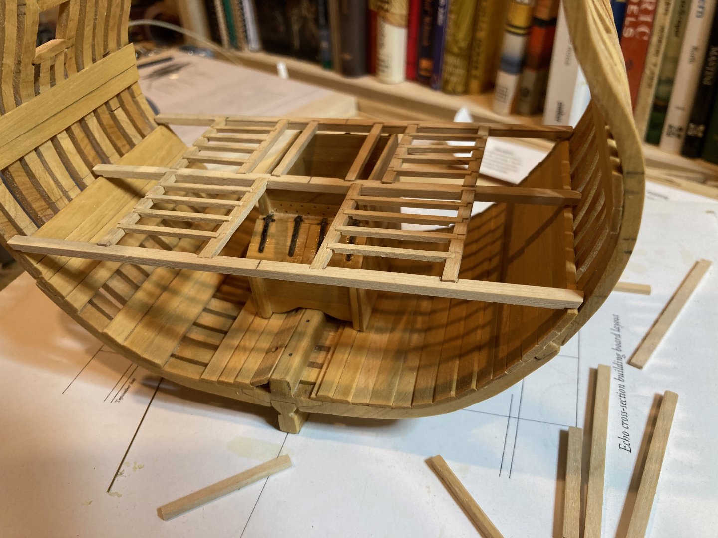
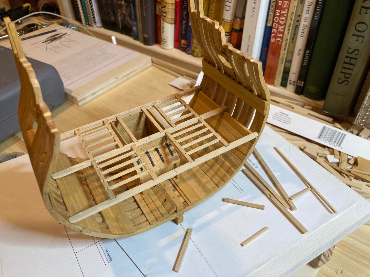
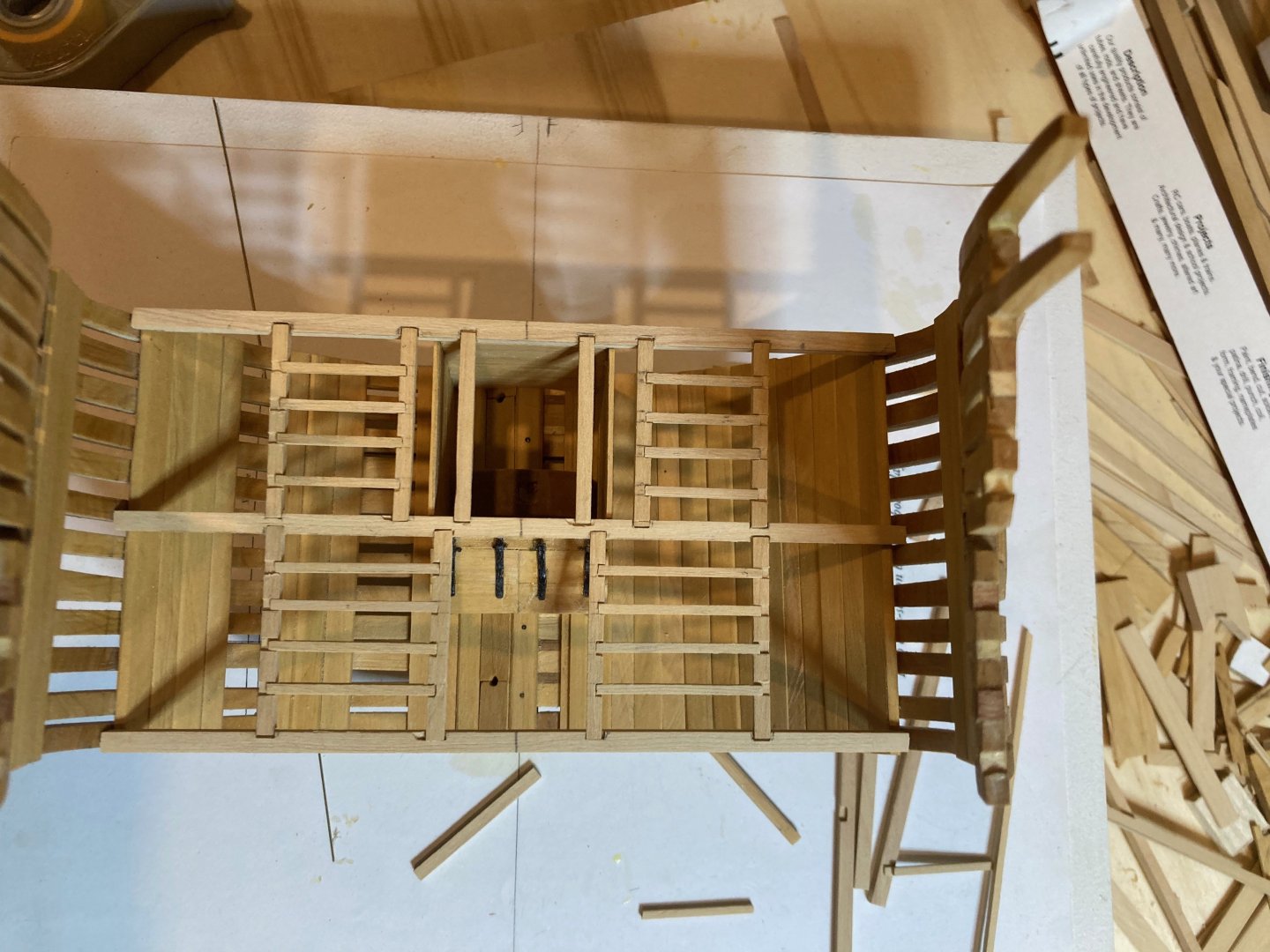
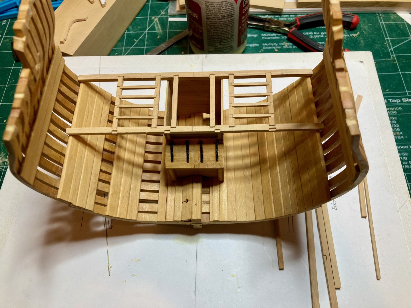
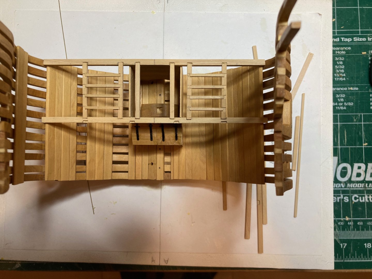
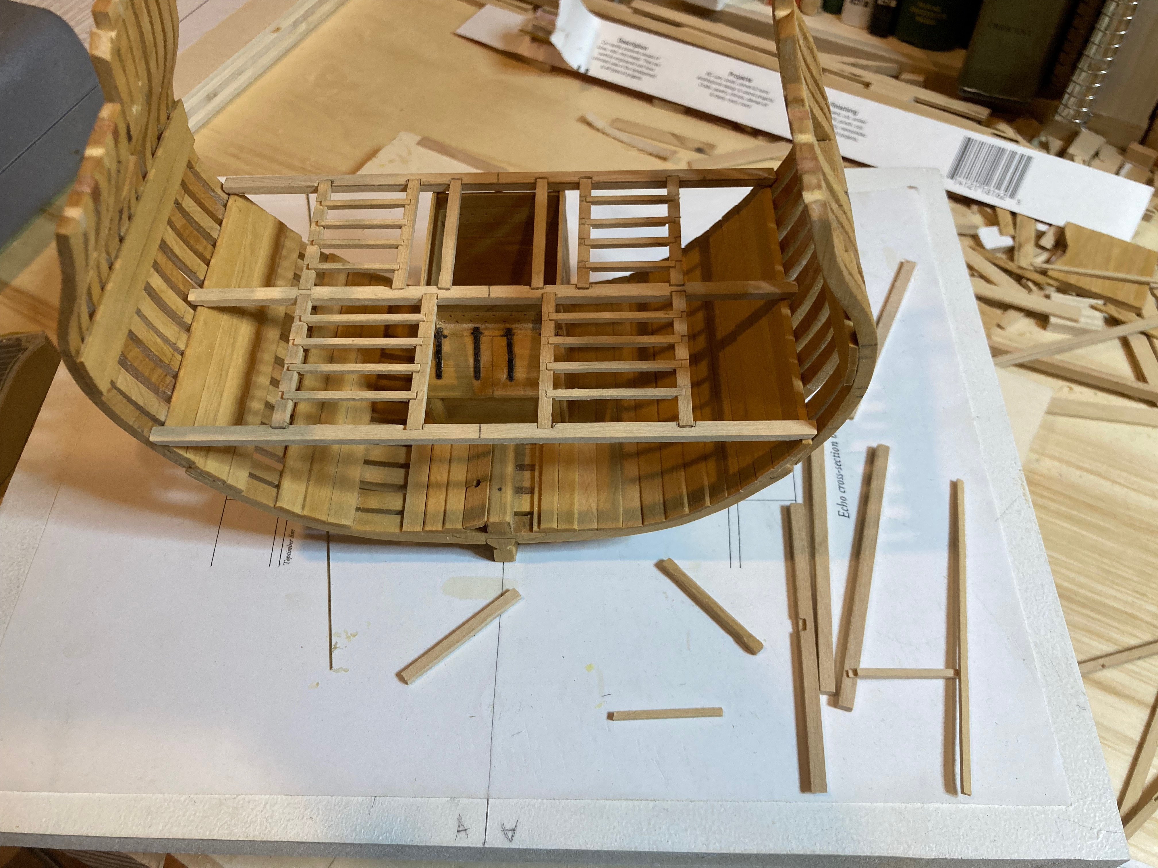
 Some progress on the deck framing - I've now finished the carlings and inboard run of ledges between the centre and forward lower deck beams. Still remaining - the lodging knees, ledges between the outboard carlings and lodging knees, and the hanging knees. Before installing the deck framing permanently, I'll also make up some blanks for the chain and hand pump shafts, a stub dowel for the main mast and blanks also for the bitt pins - and I'll need to commence on the upper deck framing, as well - this is to test and ensure good alignment of the verticals through the decks. There's so much to be considered here!! It's a bit mind-bending the first time around as I'm just kind of feeling my way around the process. The practicum is good, but some details (like where the bitt pins are positioned) are not clearly spelled out. So I feel like from this point I'll be fabricating a lot of parts without necessarily installing them. But I think that once I finish the lodging knees and ledges for the lower deck and making templates for the hanging knees, I will permanently install the well, the pillar in the hold and the lower deck framing, then add the hanging knees. Anyways, enjoy the photos! hamilton
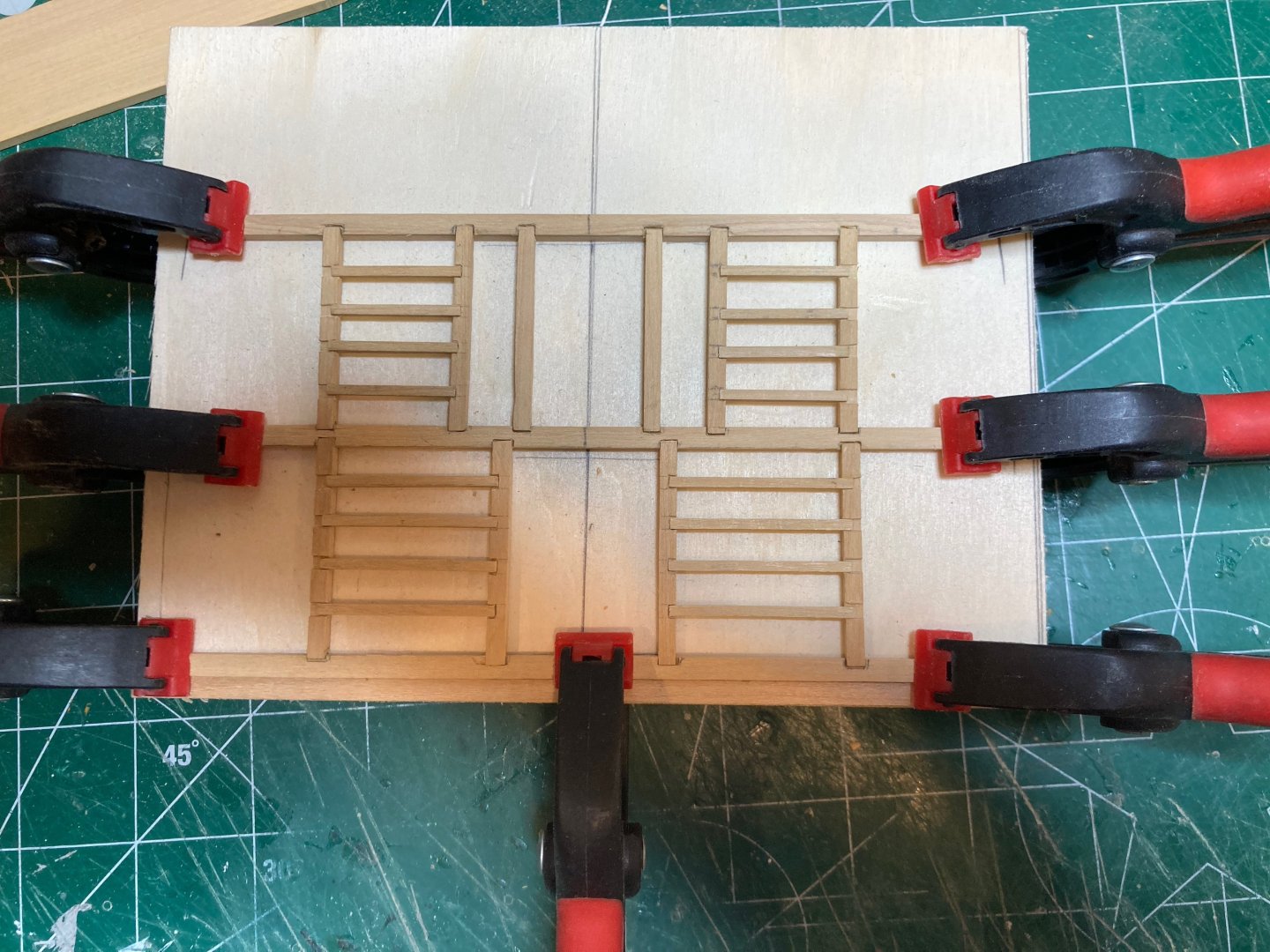
-
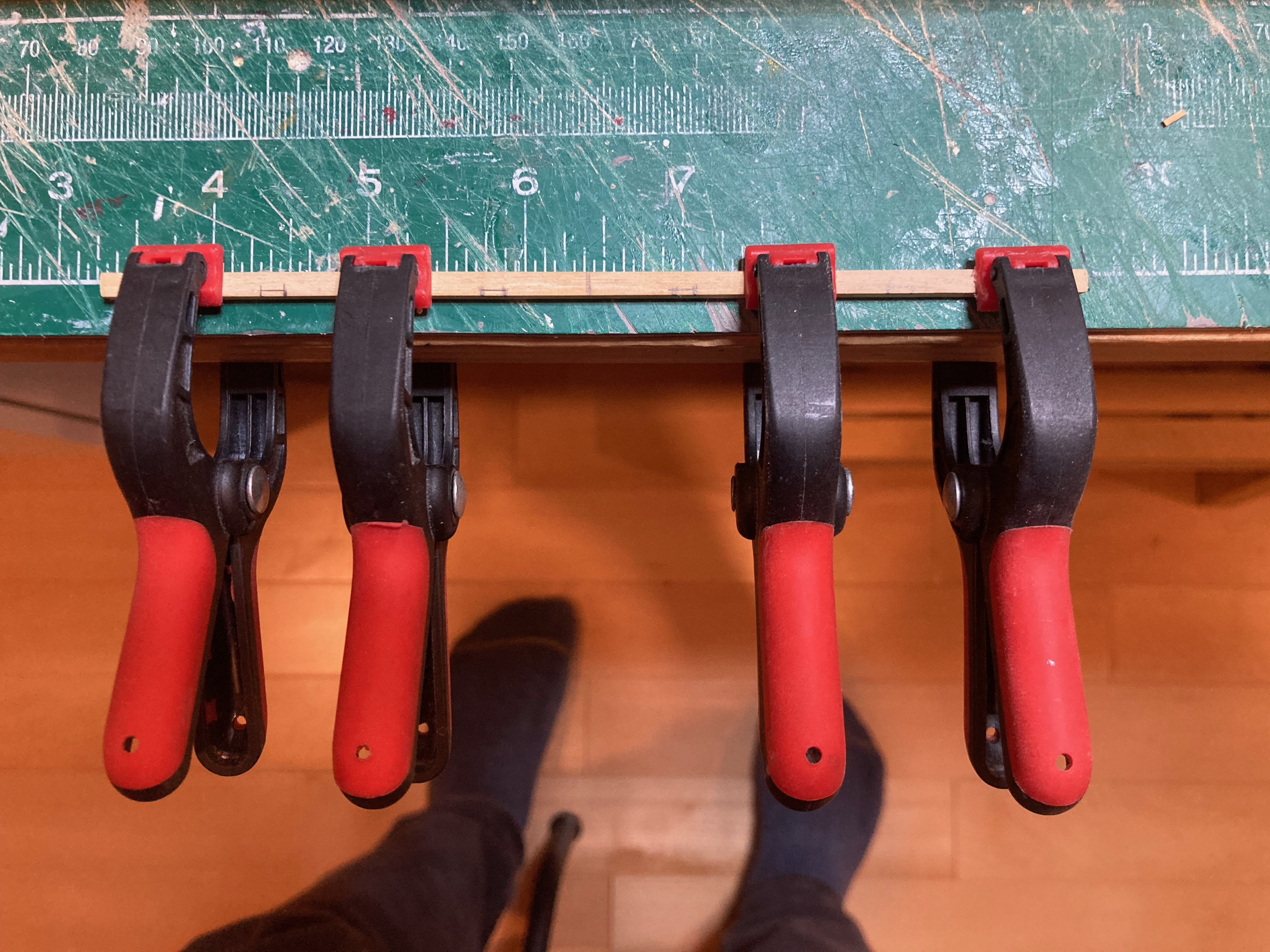
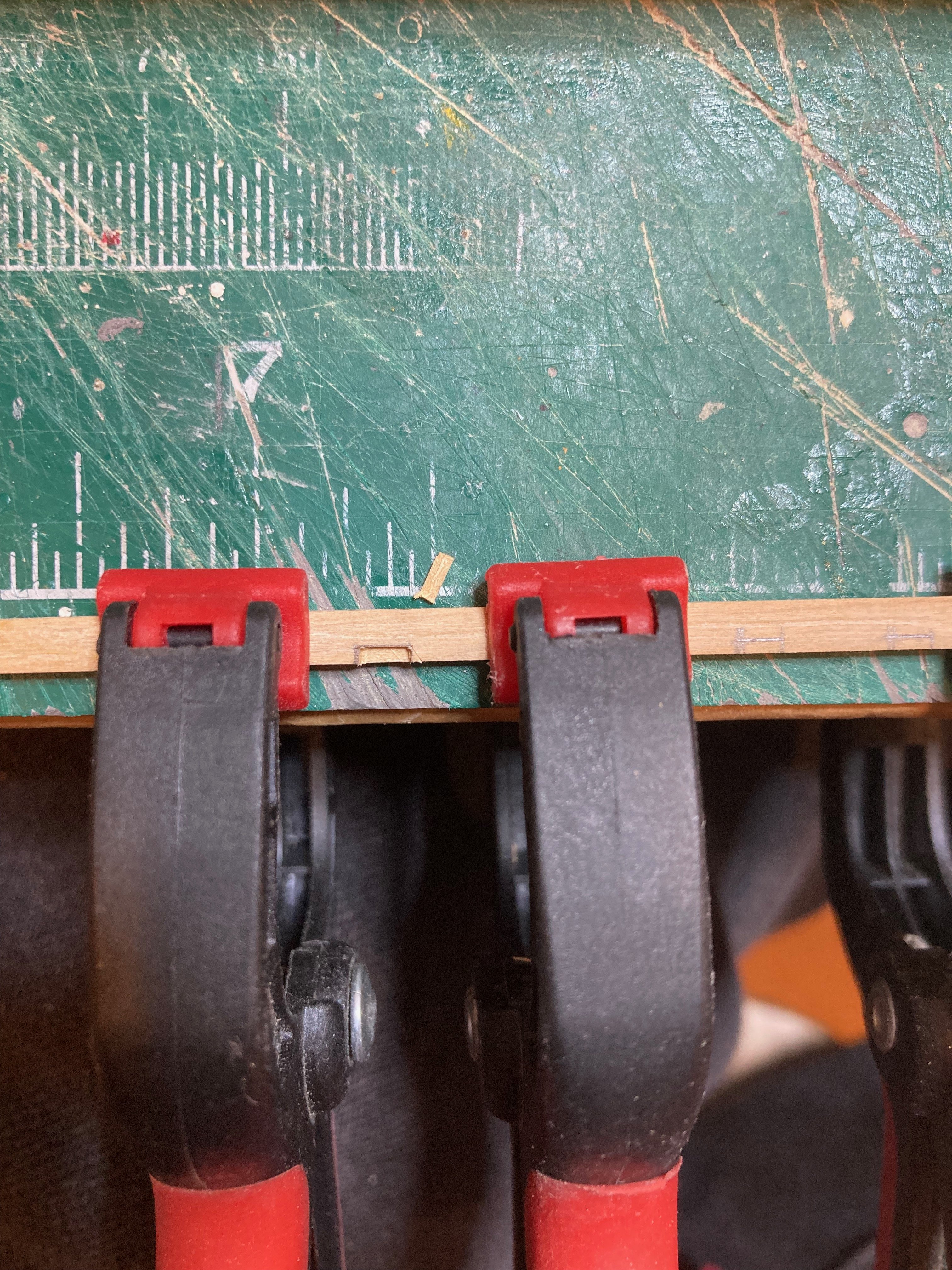
Nice work Ronald - you can never have too many clamps, eh? hamilton
-
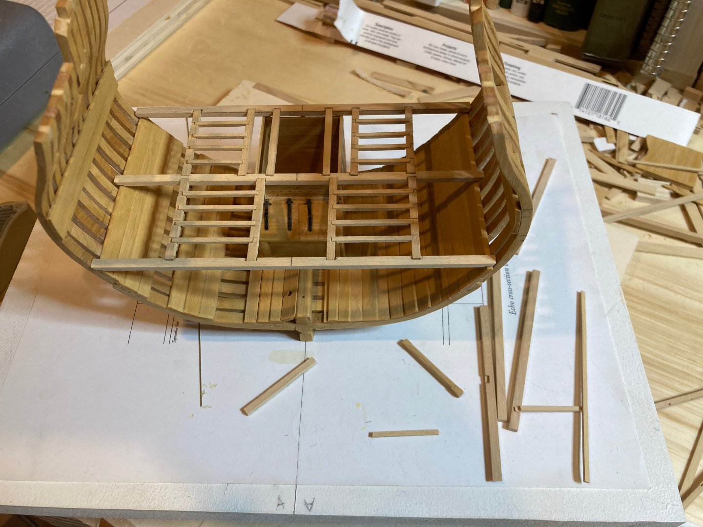
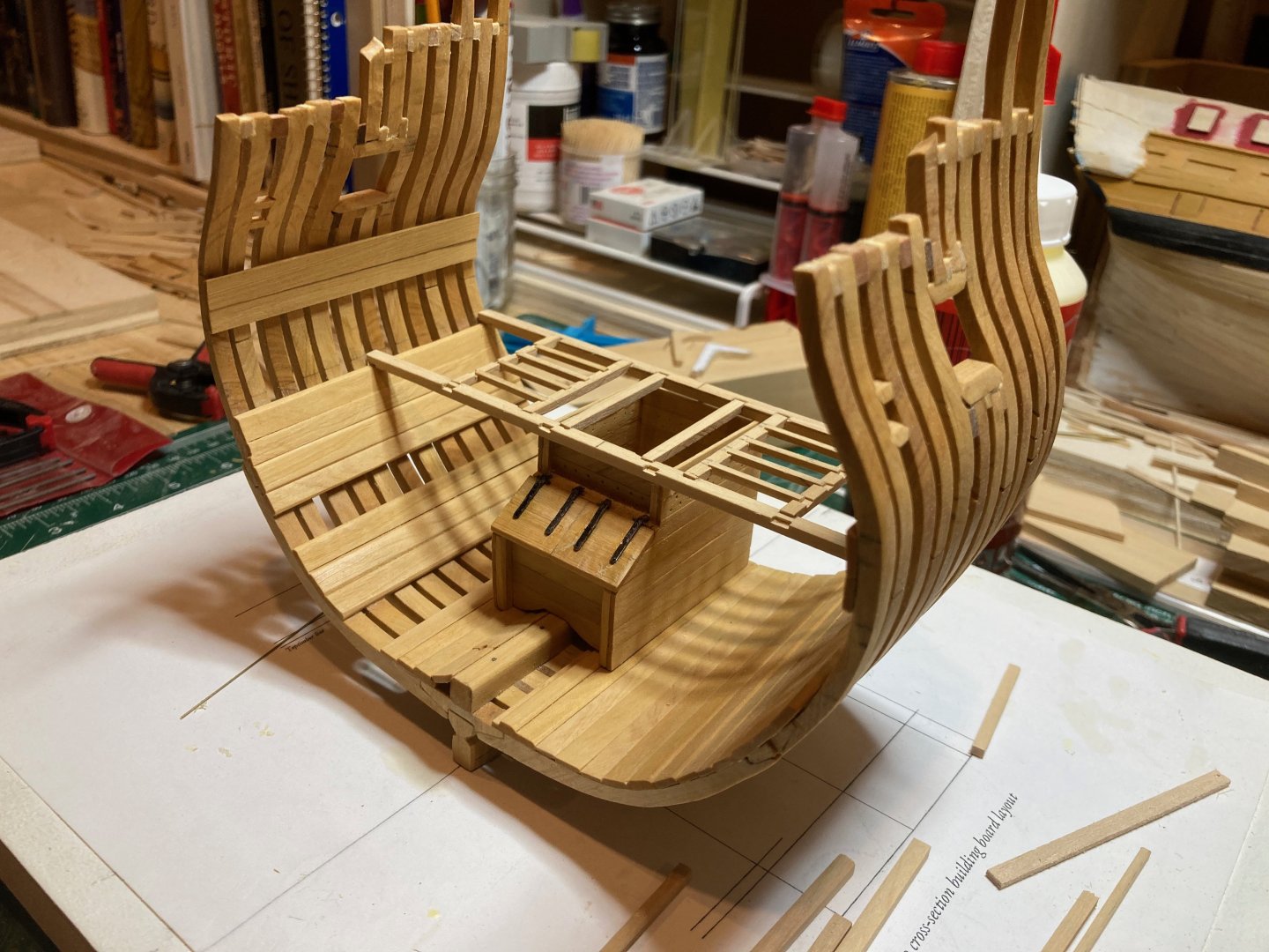
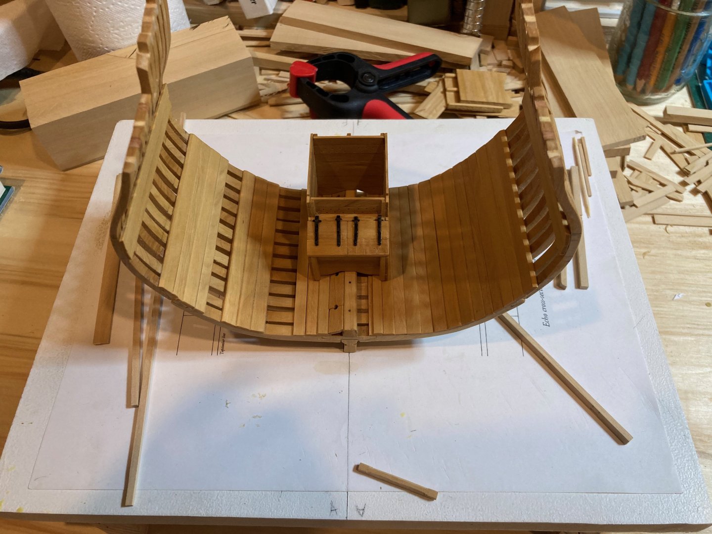
Just for fun I tried dry fitting the deck framing assembly on the cross-section - I think it looks good - the gap for the pump shafts is still a little narrow for my liking, but we'll cross that bridge when it comes.... hamilton
-
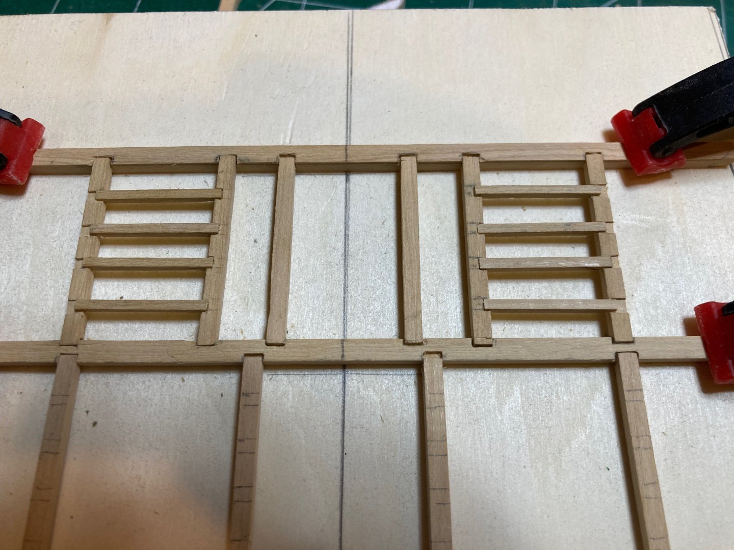
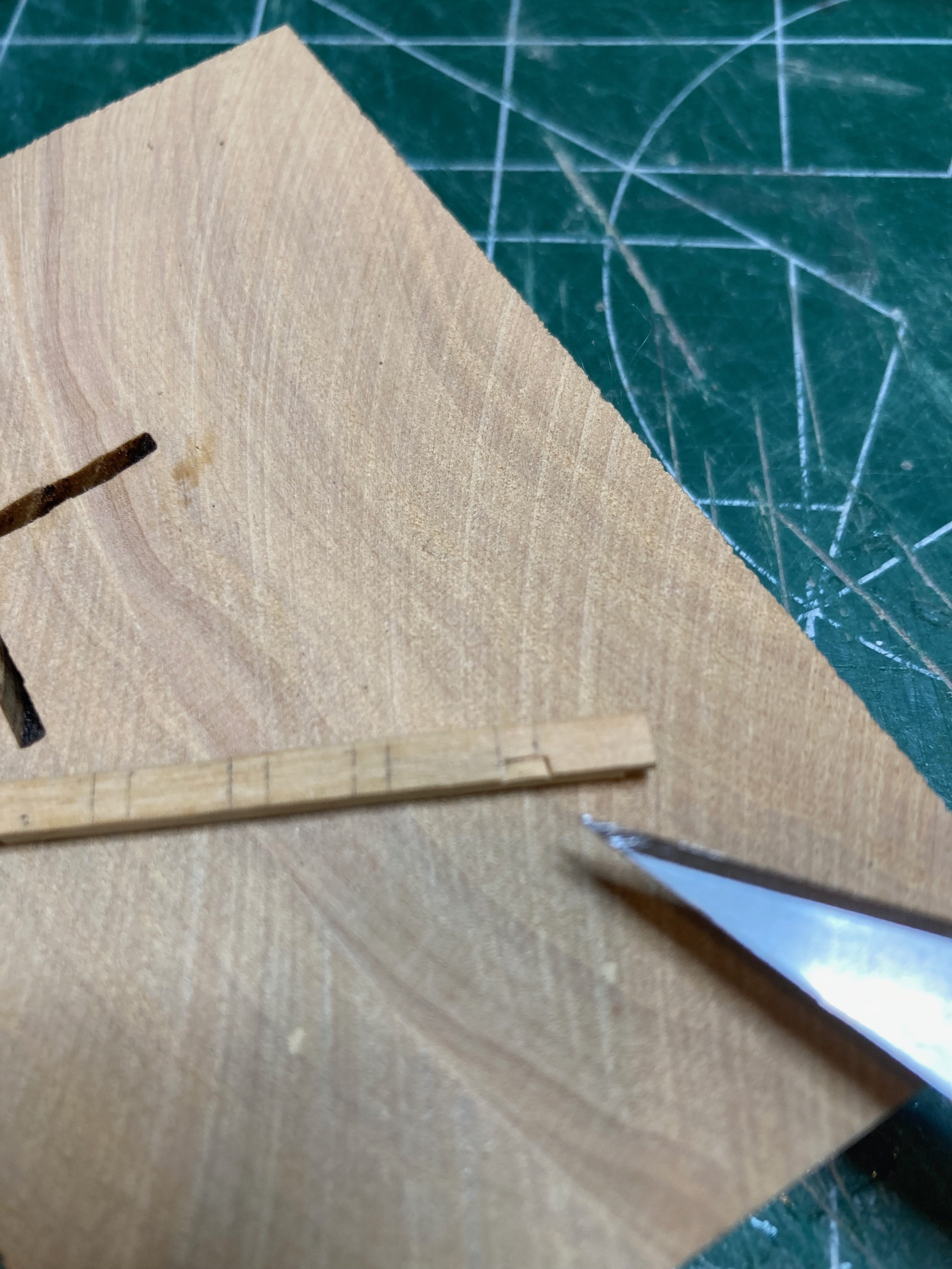
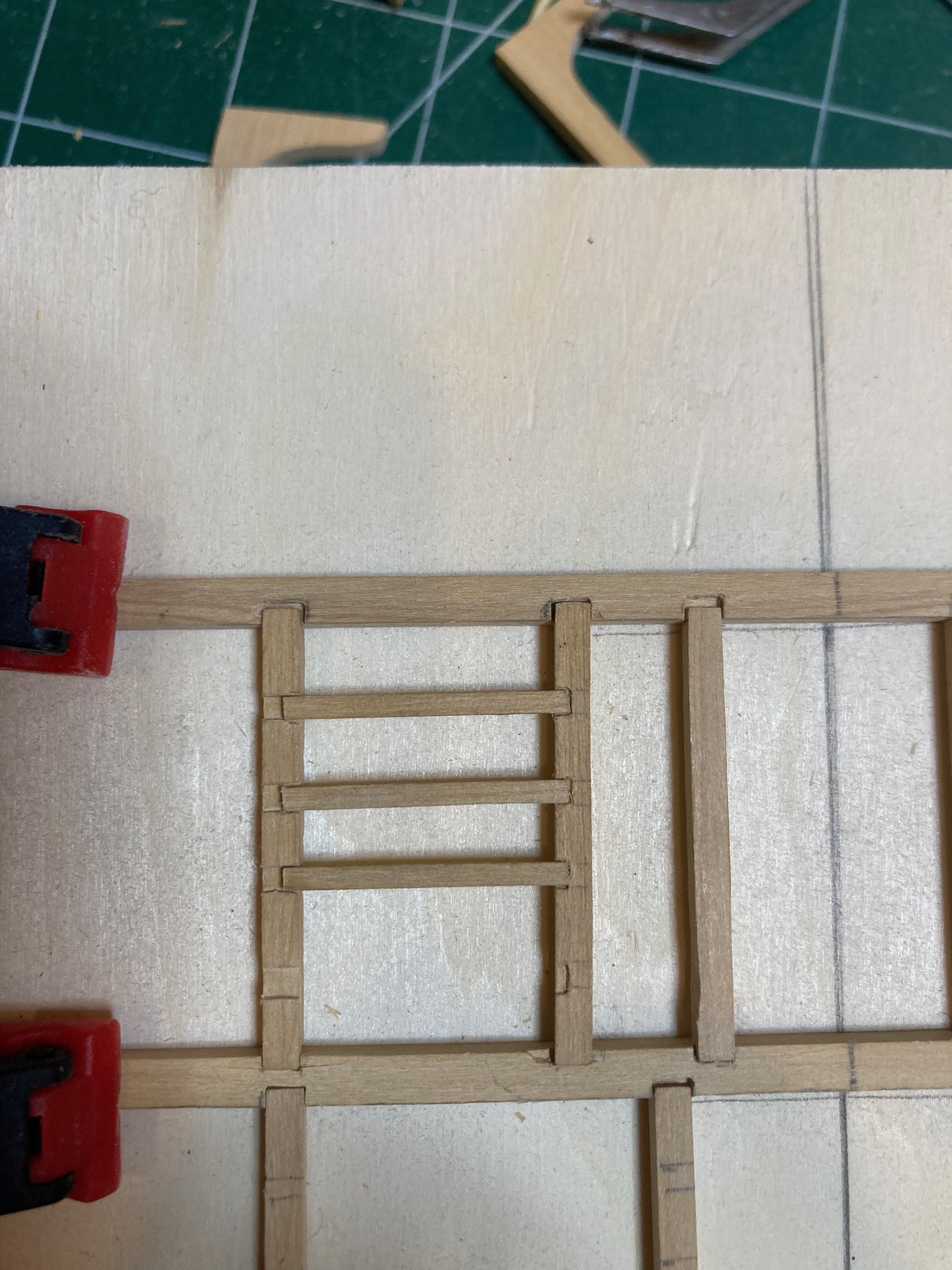
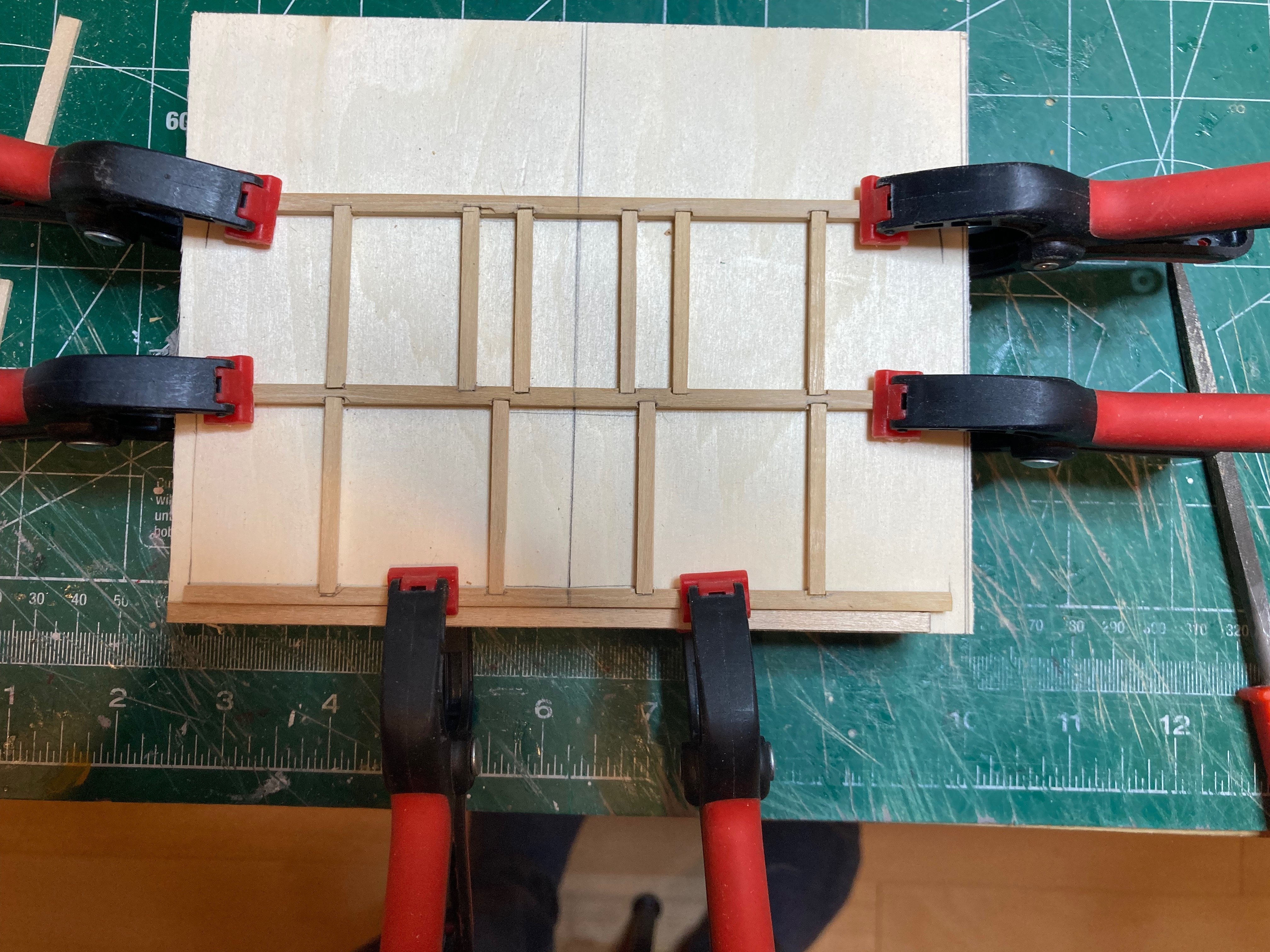
Well it's been almost a month since the last update - and though I haven't made much progress with construction, I did finally take the dive yesterday (after much humming and hawing and fretting) and started to notch out the carlings to receive the ledges. My main worry here was that without a chisel smaller than 1/8" (the carlings are 3" wide or 1/16" at scale) I would need to try to improvise some kind of cutting implement. Initially, I made a little tool out of some 1/32" x 1/16" brass strip - sharpening the end and fixing it into a wooden handle made from 1/8" x 1/8" beech. This proved ineffective. So I decided simply to use the 1/8" chisel in conjunction with a very sharp #11 x-acto blade. This worked ok, but as explained below I took a short cut with the middle carlings on each side.... The first step was to mill some 1/16" x 1/16" boxwood strips for the ledges themselves. I took a long strip, laid it across the carlings installed on my deck framing "jig" and marked out the width on the carlings to locate the notches. For the middle carlings on each side, I filed out a section, even though technically there should have been individual notches on each side - the short cut mentioned above. This saved me quite a bit of time and pains, though obviously it is not correct as per ship building practice.....At least one side of the deck will be planked and the cheat largely masked by other features, so I'm not too concerned. To cut the individualised notches, I laid my 1/8" chisel at a roughly 45 degree angle in the centre of the notch as marked out and roughly 2 scale inches from the outside edge of the carling. I tapped it in lightly - this made a "v" shaped gouge along the grain, which I furthered to the markings using the x-acto. I then used the chisel again to tap gouges for the sides of the notch. Laying the chisel carefully on the top surface of the piece, with one edge along the gouge made to define the end of the notch, I then carefully carved out the notch, cleaning it once again with the x-acto at the end. The work is not perfect, but for a first-timer it is good enough. Now that I have the process down, I was able to complete and install the first flight of carlings and ledges between the centre and aft deck beams and between the chain pump shaft openings and the middle carling. I now need to turn to the lodging knees so I can complete the ledges between the centre and aft deck beams. Before doing that (or in tandem with it) I'll keep working on the carlings and ledges in line with the main hatch (between the middle and forward deck beams)....slow going, but still fun when I can find the time!!! hamilton


-
Planking looks great so far Greg hamilton
-
Welcome (or should I say bienvenue!) Nick! I'm jealous of your Indy - such a beautiful kit! hamilton
-
Wow - what a spectacular landscape - and an incredible adventure! I've not been further North than Rainbow Lake Alberta - there is just way too much Canada to deal with!! Glad that you shared this experience with us Jond hamilton
-
Love the generosity in sharing your process Cisco! The gorgeous results are one thing - how you get there makes it even better! hamilton
-
You've built a truly gorgeous version of the Bluenose Gregg - love her without the sails so the focus can be on the beauty of the hull lines and the lovely spider's web rig. Hope you've got a nice display area worked out for such a fine rendition. hamilton
- 184 replies
-
- 2
-

-

-
- Bluenose
- Model Shipways
- (and 1 more)
-
Love to see the proud Nova Scotia flag flying high on the foremast - great work Gregg! hamilton
- 184 replies
-
- 1
-
-
- Bluenose
- Model Shipways
- (and 1 more)
-
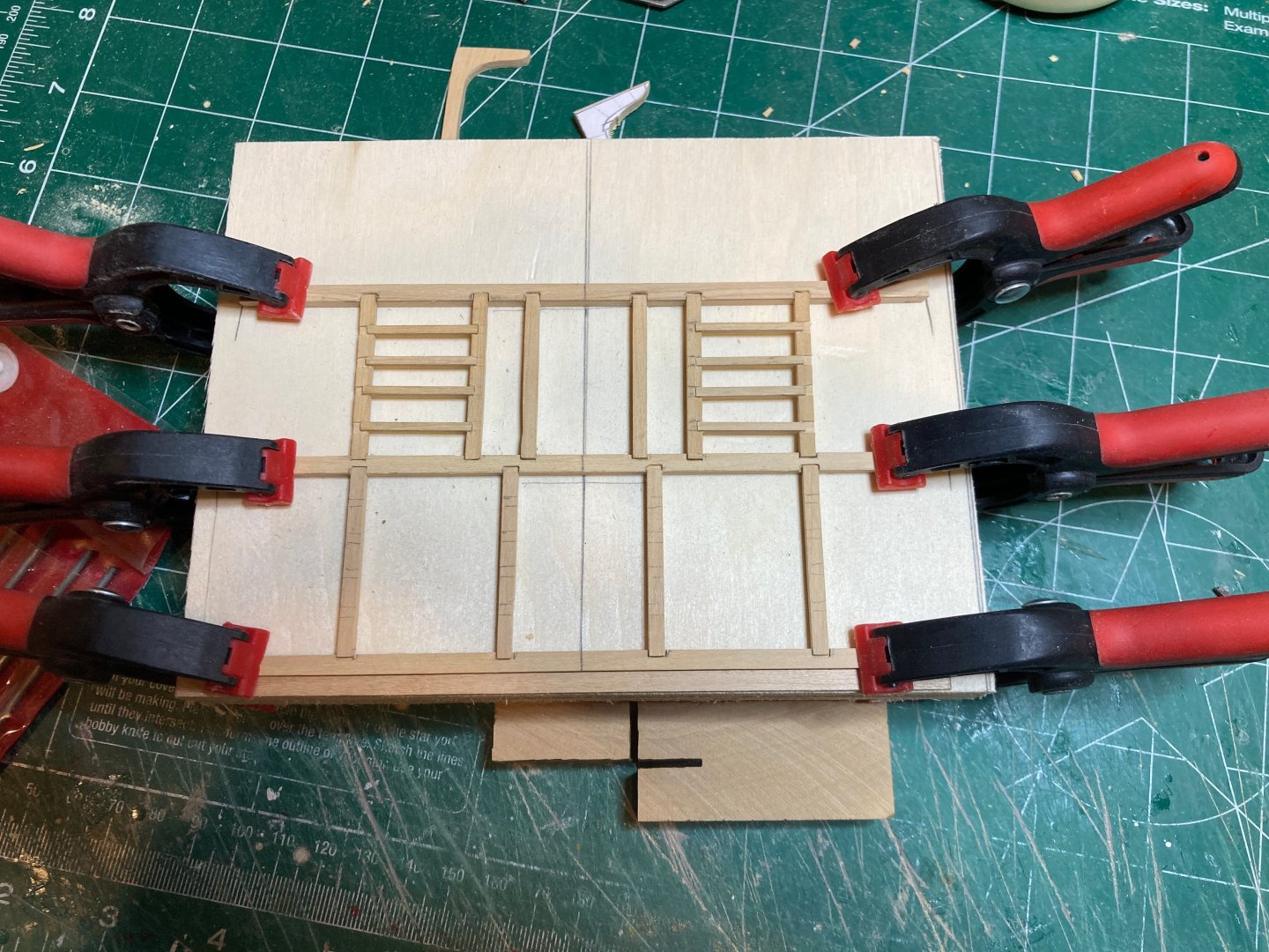
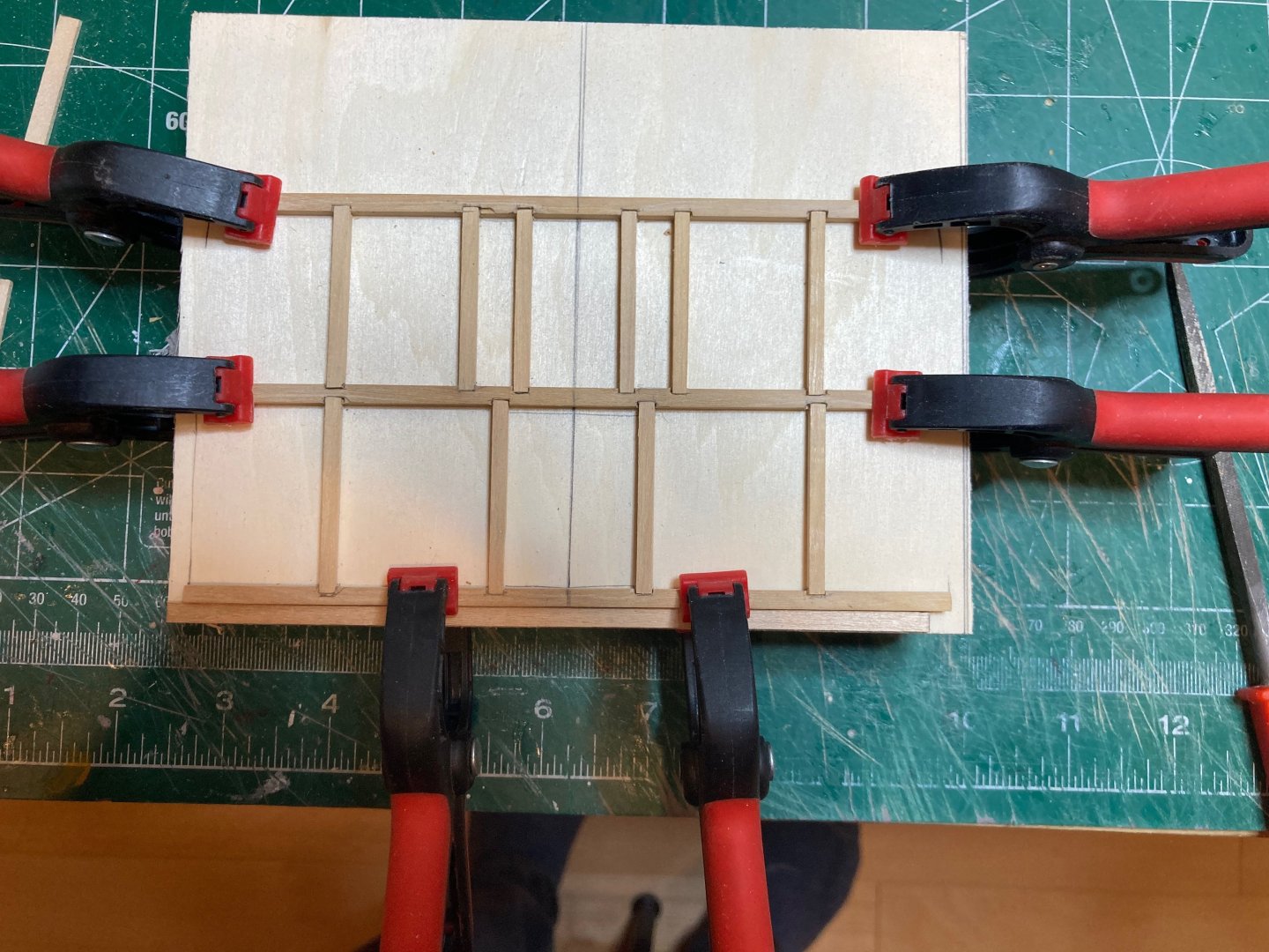
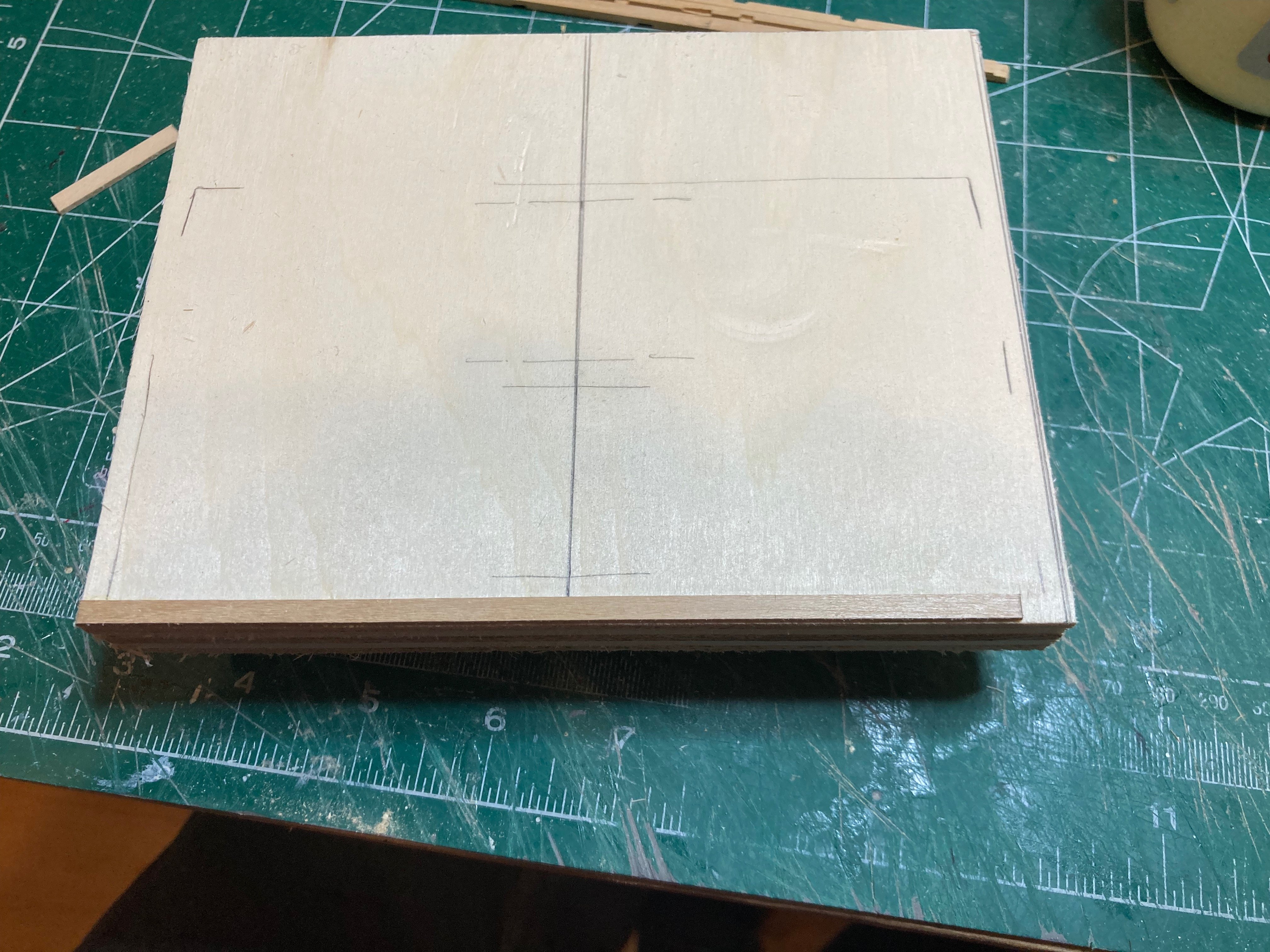
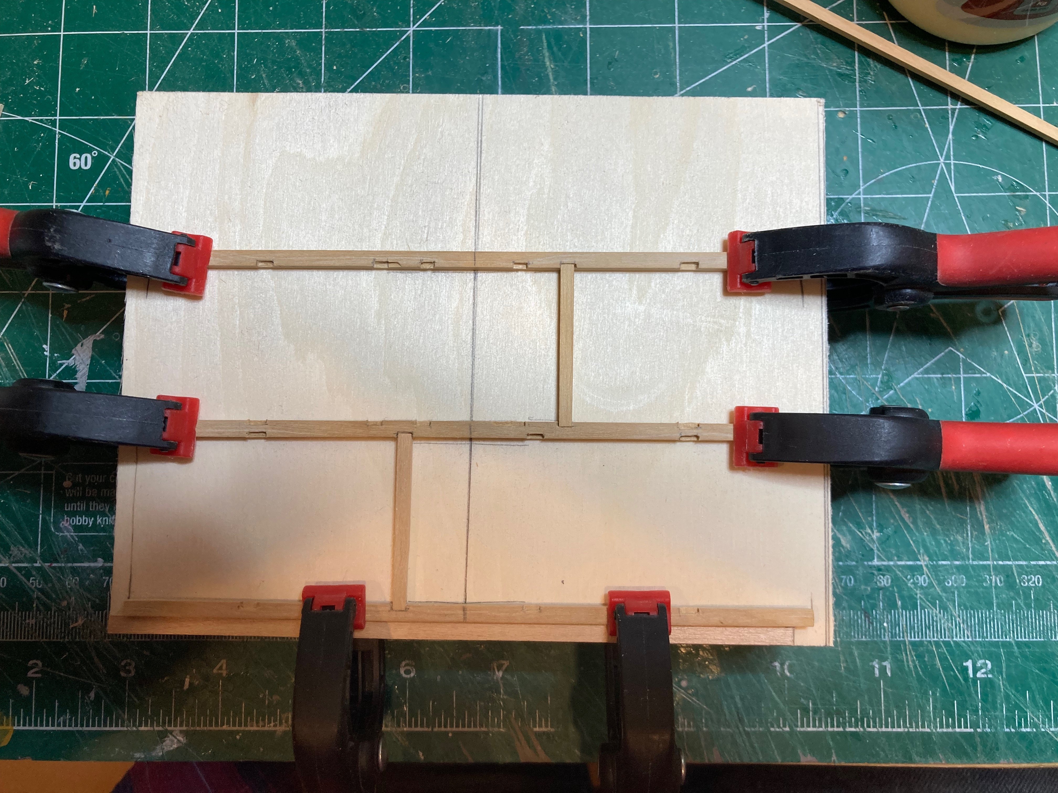
Ok - one last post seriously!! I made the jig referenced above for the deck framing and cut/notched out all the lower deck carlings. It was very tempting to install them on the deck beams, but I know I will have to notch them out for the ledges, so I have to be patient!! I cut a small piece of 3/4" ply and attached some 3/4" x 1/2" scrap wood strips to the bottom as risers. I then glued a 1/64" strip to the bottom edge as an anchor and marked out the position of the deck beams from the template I made earlier. I then clamped the deck beams to the board and cut each carling to length individually. As I went there were a couple of places where the notches in the deck beams had to be adjusted slightly to seat the carlings squarely. But I think there were only 2 or 3 of the 20 that needed this, which is a decent ratio I'd say. And now, a hiatus from building to focus on work and vacation...might be a few weeks or so before I have enough free time to really get moving again on Echo, but we'll see.....bye for now hamilton


-
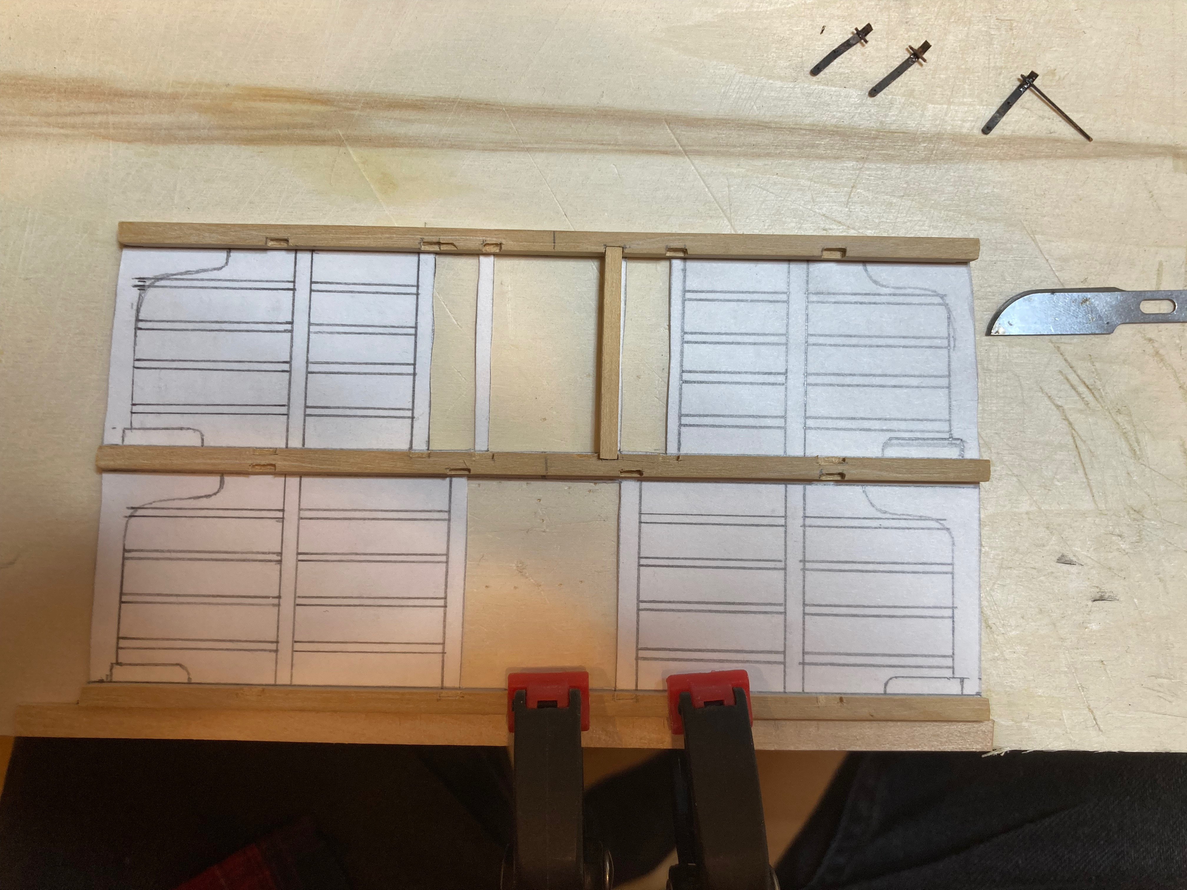
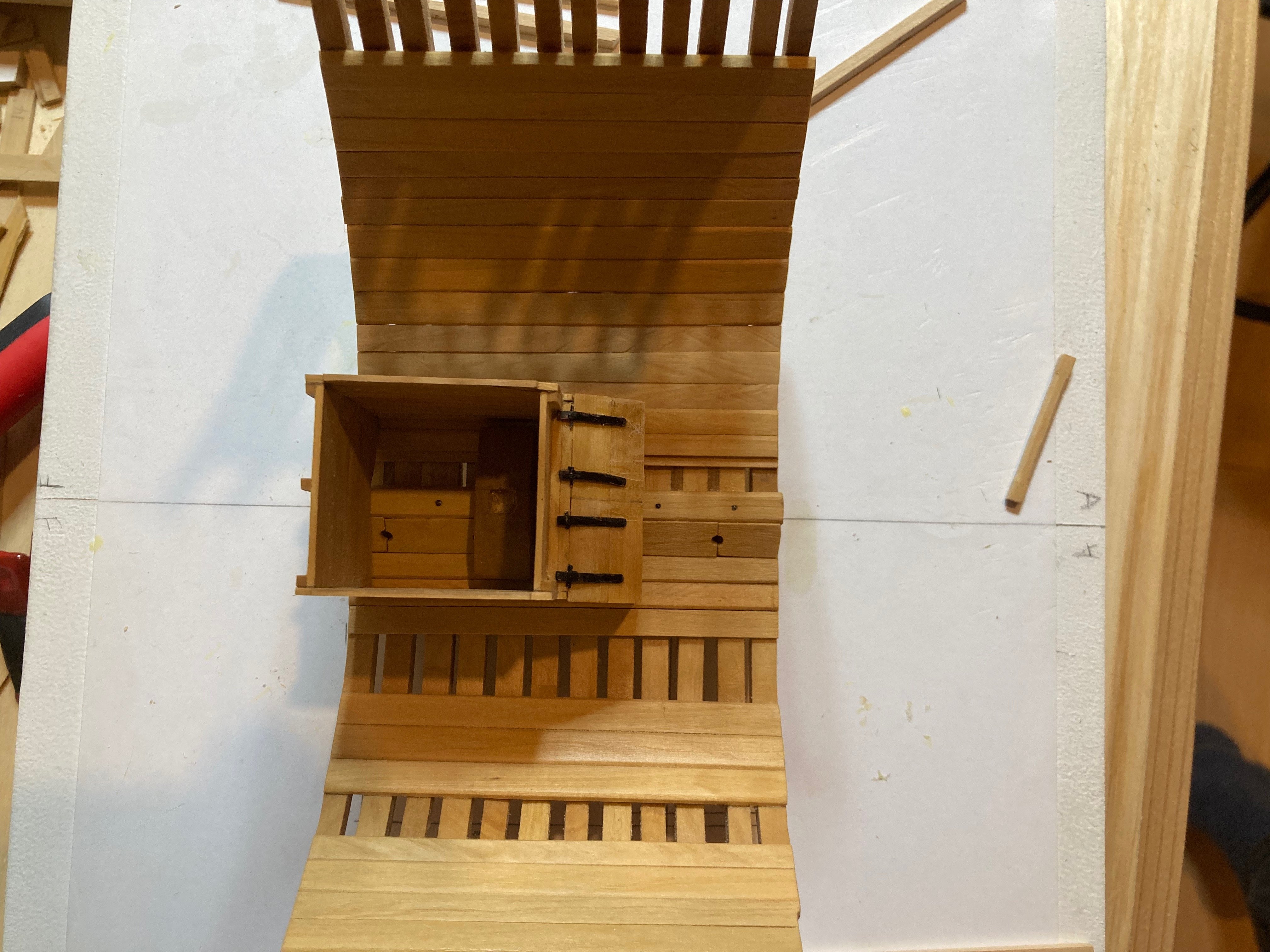
Last pics of the day - the well with hardware attached - I will re-do the inboard port side hinge as it got a little twisted when I was using the awl to (pretty ineffectually) simulate bolt heads by punching out from the back side.....in any case it's a little rough-looking, but I thionk it'll be fine once the twisty hinge gets corrected.... hamilton


-
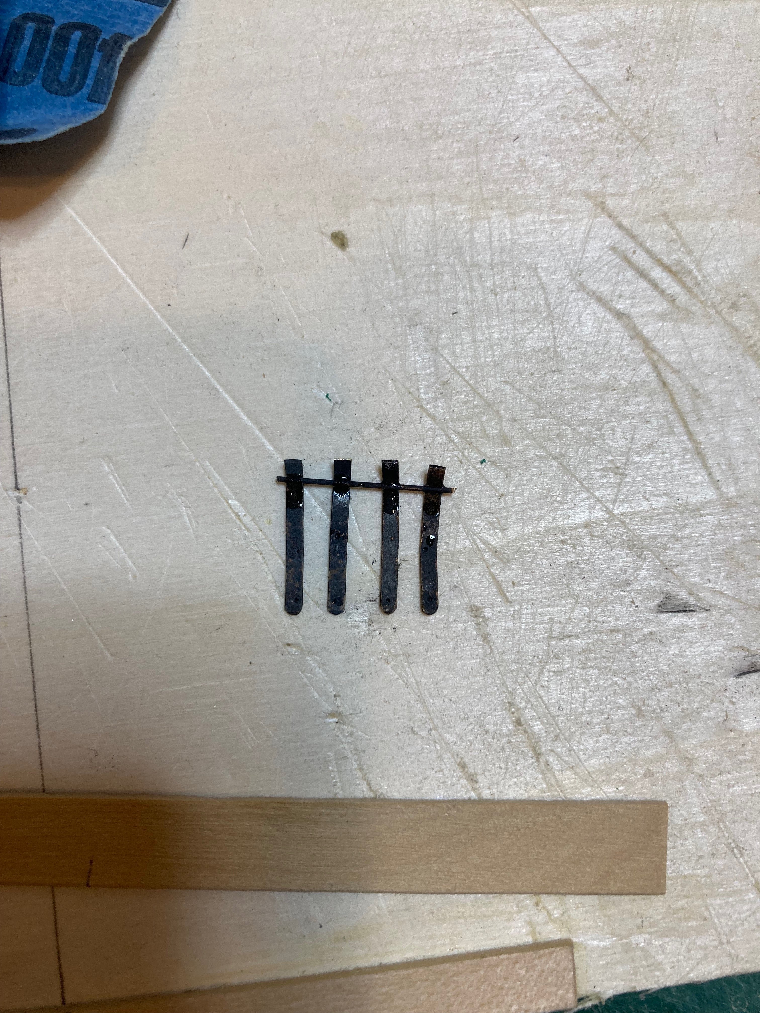
Very much a kind of "in process" update. I've started on the hinges for the well using 1/64" x 1/16" brass rod, rounded at the ends and punched with a sharp awl to simulate (not very effectively) the bolts. I tried drilling through the brass, but this proved to be no easy task - assuming that softening the metal in advance by heating it might make this easier, but.....I used some very thin blackened wire to simulate the hinge pins. The photo below shows the hinges hanging off the wire, which will be trimmed back before installation. The wire is connected with a small drop of CA and I'll use epoxy to fit them onto the shot locker lids. But the main work this morning was notching out the lower deck beams for the carlings. As a first step, I lined up the beams to mark out the centre lines and then marked the position of the notches to ensure that the carlings would run true between the beams - this took a bit of finessing. I adjusted the carlings around the lower mast partners/slots for pump shafts to address the alignment issues noted above - they were moved inboard by 1.5" in each case, narrowing the mast partners slightly but allowing for (I think) better clearance of the pump shafts. There were a couple of notches where I ended up tearing out a little bit of wood outside the area - this only affected one of the beams and only on the starboard side, so I've decided that is the side I will add deck planking to - the tear-outs will be completely hidden and will save remakinf the beam. I was initially a little worried about carving out the notches, but the 1/8" chisel is the perfect size, and I ended up clamping the beams along a strip of 3/64" basswood, which allowed me to cut out the notches at the right depth and gave more control to the work. It was much less tricky (though it was pretty slow going) than I thought it would be - the 3" ledges will be another matter, since I do not have a 1/16" chisel to do the work that the 1/8 chisel did on the carling notches.....At this point, I think my only option is to try using a #11 blade for these much small notches....but we'll cross that bridge when the time comes.... I'm thinking that I will make a jig to assemble the deck beams, carlings (carved out for ledges) and lodging knees and then install this as one piece onto the model before fitting the ledges and hanging knees. The jig will consist of a 3/4" piece of MDF as a base a little larger in dimension to the overall deck surface, and with some wood strips added on the bottom to raise it for clamping purposes. I will then fix the deck framing template to the upper surface and fix thin (3/64") basswood strips between the beams to keep them evenly spaced. I'll then clamp the beams to this jig and fit the carlings and lodging knees and glue it all up. Since there is no round up to this deck this should be a workable approach. I'm also a little nervous about the hanging knees - these seem like incredibly finicky parts to make - the joinery along the thick stuff and ceiling planks will be hard to get exact....but again, nothing for it but to give it a try.... The coming week is going to be quite a busy one as I have a tonne of work to get through before we head on a brief vacation for my wife's 50th....and it'll be pretty full on when we get back, so I'm not sure how much time I'll have at the bench in the next several weeks - I would like to get the well fully completed and the deck framing jig made, but even that might be a bit too ambitious....we'll see. Happy modelling and bye for now - enjoy the photos hamilton


.thumb.jpeg.16f72e67c03267c628e707b61c402d28.jpeg)

-
Yeah - it seems like the planking approach they suggest is trying to reinvent what are much better approaches seen on this forum. Your garboard looks very well placed - it;'ll be good to see the planking come along hamilton
-
Thanks @JacquesCousteau! I see you're located (at least partially) in Mexico City - I'm heading there next week and wondering if you have any recommendations for things to see/do other than the obvious musts (Teotihuacan, Zocallo, the Anthropology museum, Kahlo/Rivera type things, etc.)....restaurant recommendations are always welcome!! hamilton
-
Just as a follow up - I've almost completed the third (and final!!) version of the well, with very limited time at the bench. When I dry fit this version and laid my lower deck template on top of it, there was the same issue with the carlings, but what I really wasn't doing when I "discovered" the alignment issue earlier was considering the angle of the pump shafts. When looking straight down, the problem of clearance around the carlings is severe, but when examined from the approximate angle of the pump shafts it's not quite as bad and if the carlings are shifted inboard by even a small amount (3 scale inches) the alignment seems more or less reasonable. Working through a batch of student essays at the moment and other pressing work demands, but hopefully I'll find some time this weekend to finish this part of the build off and commence on the next (lower deck framing) as most of my family will be away and work will slacken slightly.....bye for now hamilton
-
She is going to be sweet! hamilton
-
Good to follow you're instincts - they did you well! hamilton
- 422 replies
-
- 1
-
-
- Vanguard Models
- Sphinx
- (and 1 more)
-
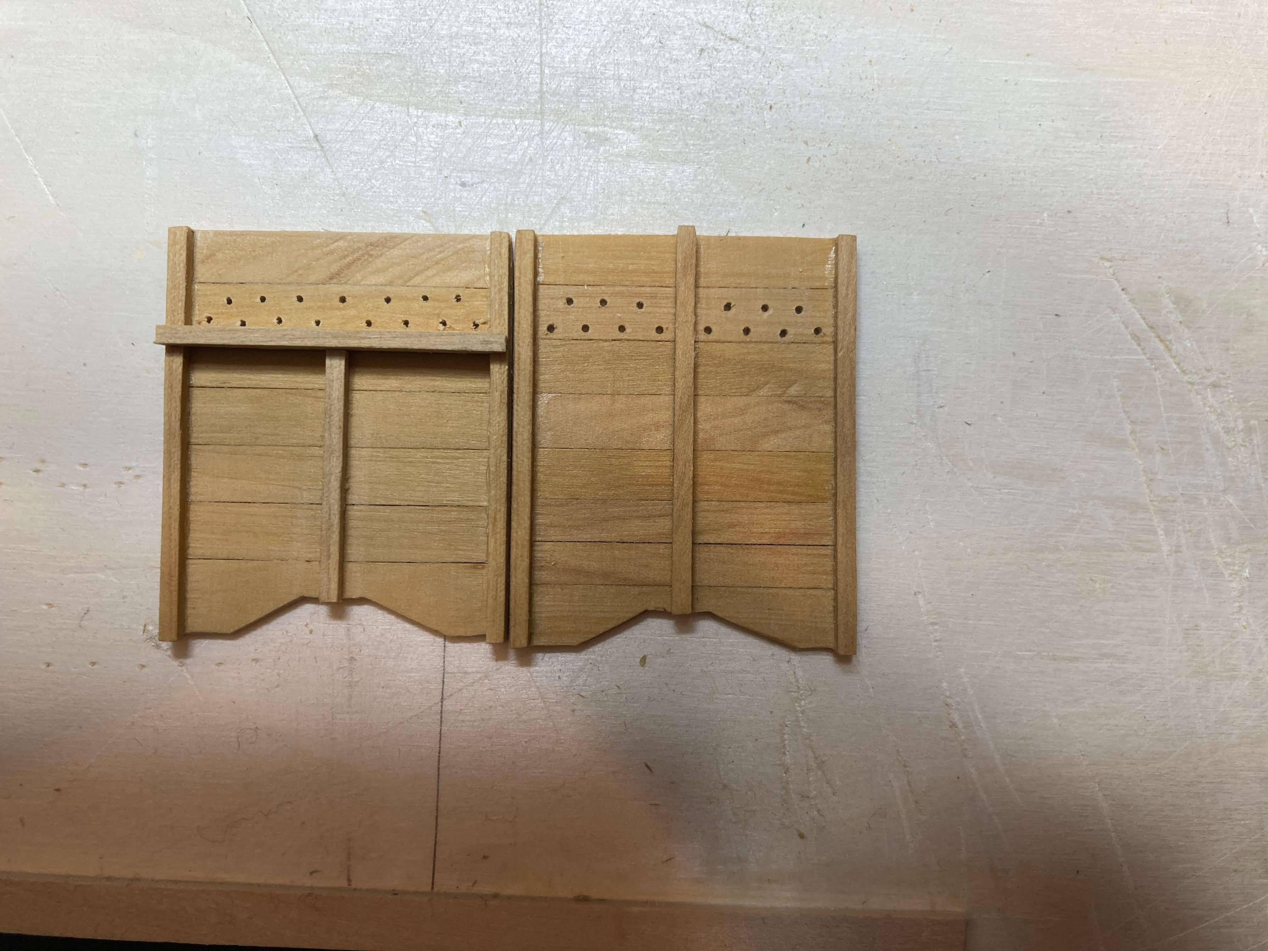
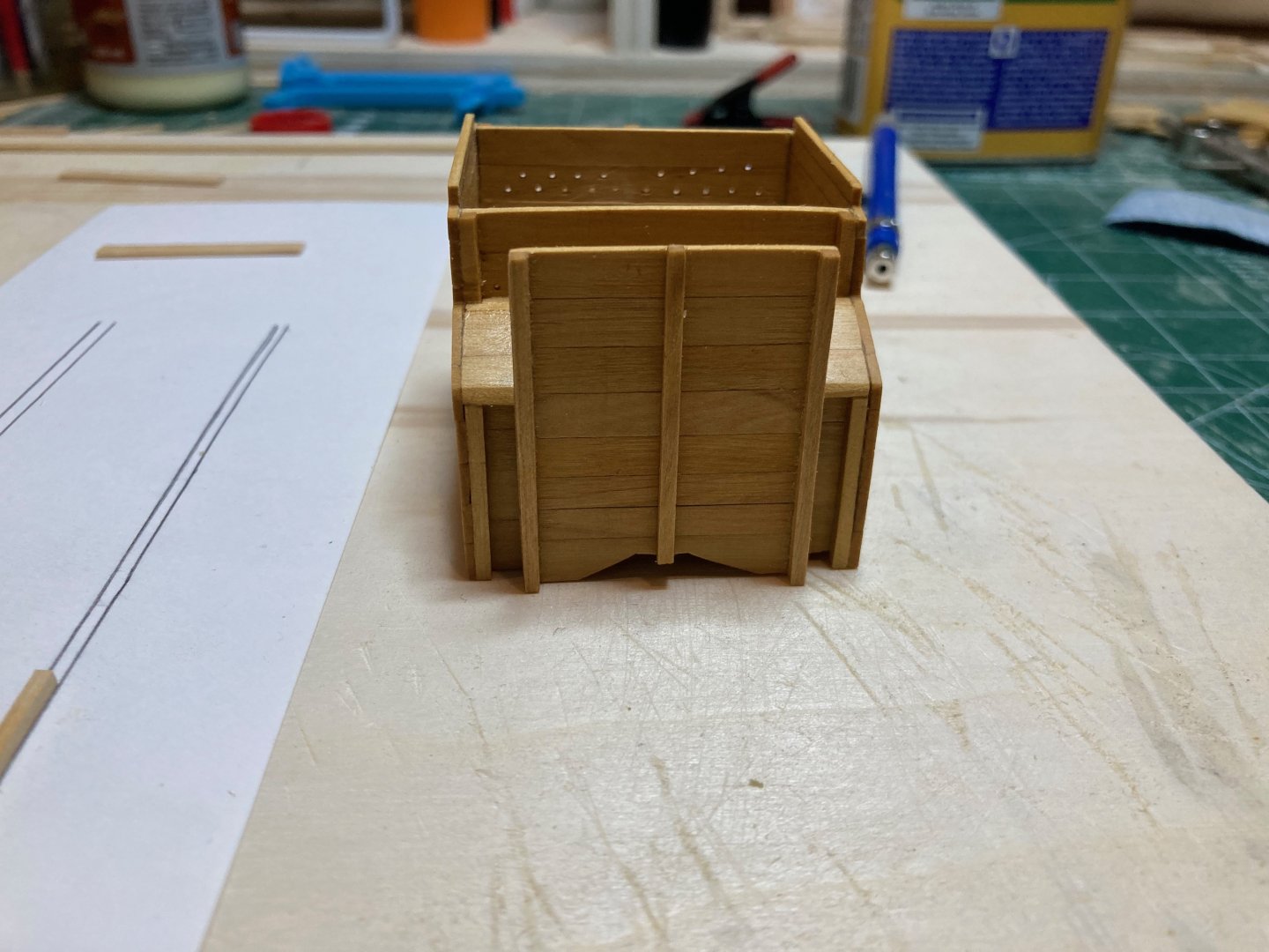
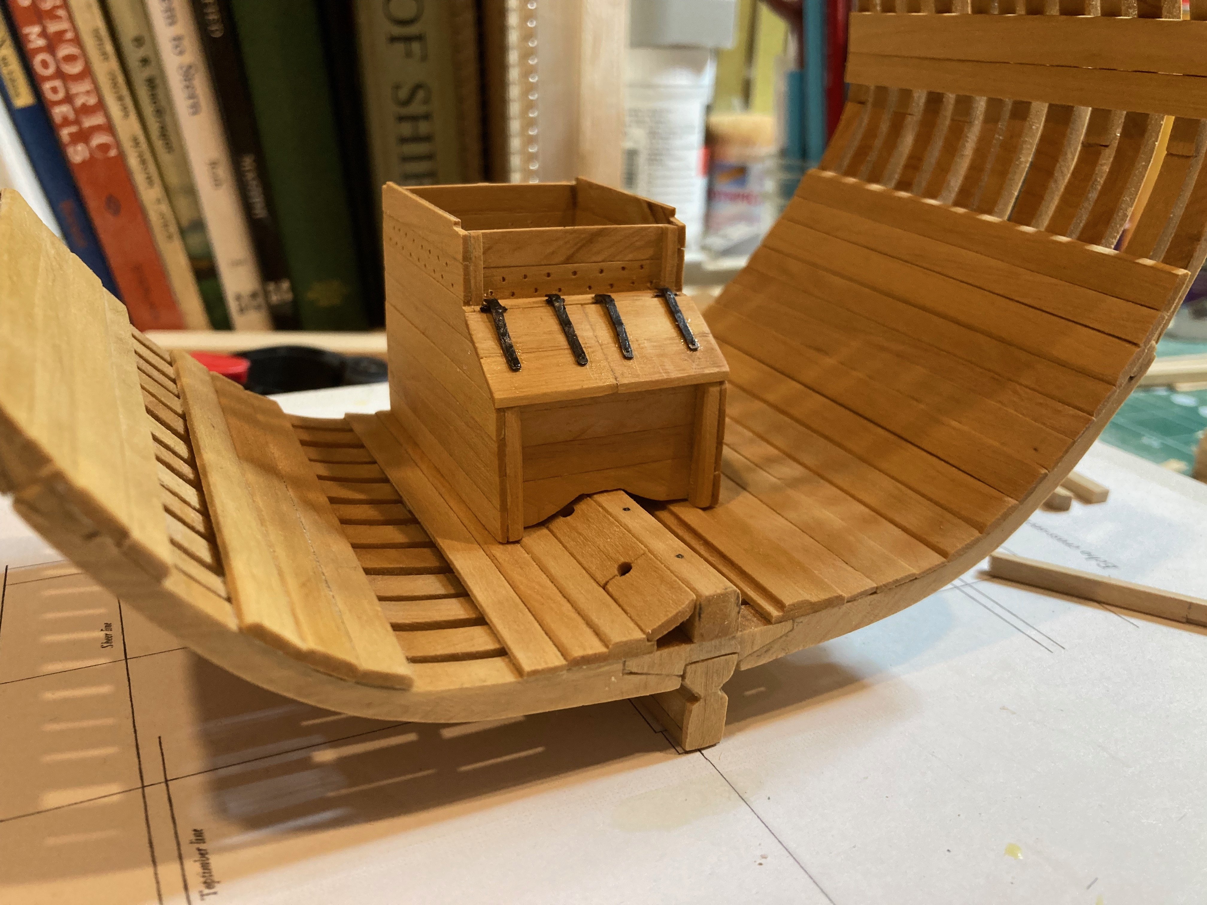
So people (including me) are probably getting tired of the well! But I'm into my third version now and wanted to post a couple of shots to show the current state and comparison with the chubby well I made to compensate for the alignment issue with the lower deck framing noted above. The consensus here seems to be to go with the well as defined in the contract and then fudge the pump shafts. I wonder if this will just look bad....or weird....but then the alternative is to use the chubbier well and risk throwing off alignment of the shafts through the upper deck, which would also look bad....or weird....The lesser evil seems to be the first option, but I'm not sure I'm entirely happy with it.... In any case, I'm learning how to quickly throw together a well!! And certainly each successive version has been an aesthetic improvement on the last, which is good to see.....here are the shots - not sure if I'll get any time at the bench this weekend - a stack of marking to get through this weekend plus the usual household duties, so......might have to limit myself to watching others! hamilton

-
PS - if Model Shipways' approach was merely to photographically enlarge their old drawings (which it kind of looks like it was), then there is likely to be some distortion in the 1:48 line drawings....though from what you show of them above they could, theoretically, be used to make templates to check against the parts..... hamilton
-
Yeah - not sure what use that is except for locating parts.....I guess you could check symmetry of the laser cut parts on the line drawings included on the other plan sheet - but that would involve some lofting from the drawings....does the sheet with the line drawings on it have a scale measure on it to check for distortion? hamilton
-
Glad to see that someone is starting a log for this - like you, the 1:96 Phantom was my very first ever ship model and the first I brought to completion - the one that hooked me! Have been tempted by this larger version, particularly since my old Phantom had to be consigned to the dustbin after a major accident....I did notice from the Model Expo website that the plans seemed to be identical to the 1:96 plans, just enlarged....did they at least add a sheet with laser cut patterns? In any case it'll be fun to see her come together here! hamilton
-
Very nice work! hamilton
-
Looking good Bob! Someday I'll build a Vanguard model...they look so nice!! hamilton
- 207 replies
-
- 3
-
-
-
- vanguard models
- Duchess of Kingston
- (and 1 more)


.jpeg.cc12f53dc93587c42b8077a63ac50766.jpeg)