hamilton
-
Posts
1,933 -
Joined
-
Last visited
Content Type
Profiles
Forums
Gallery
Events
Everything posted by hamilton
-
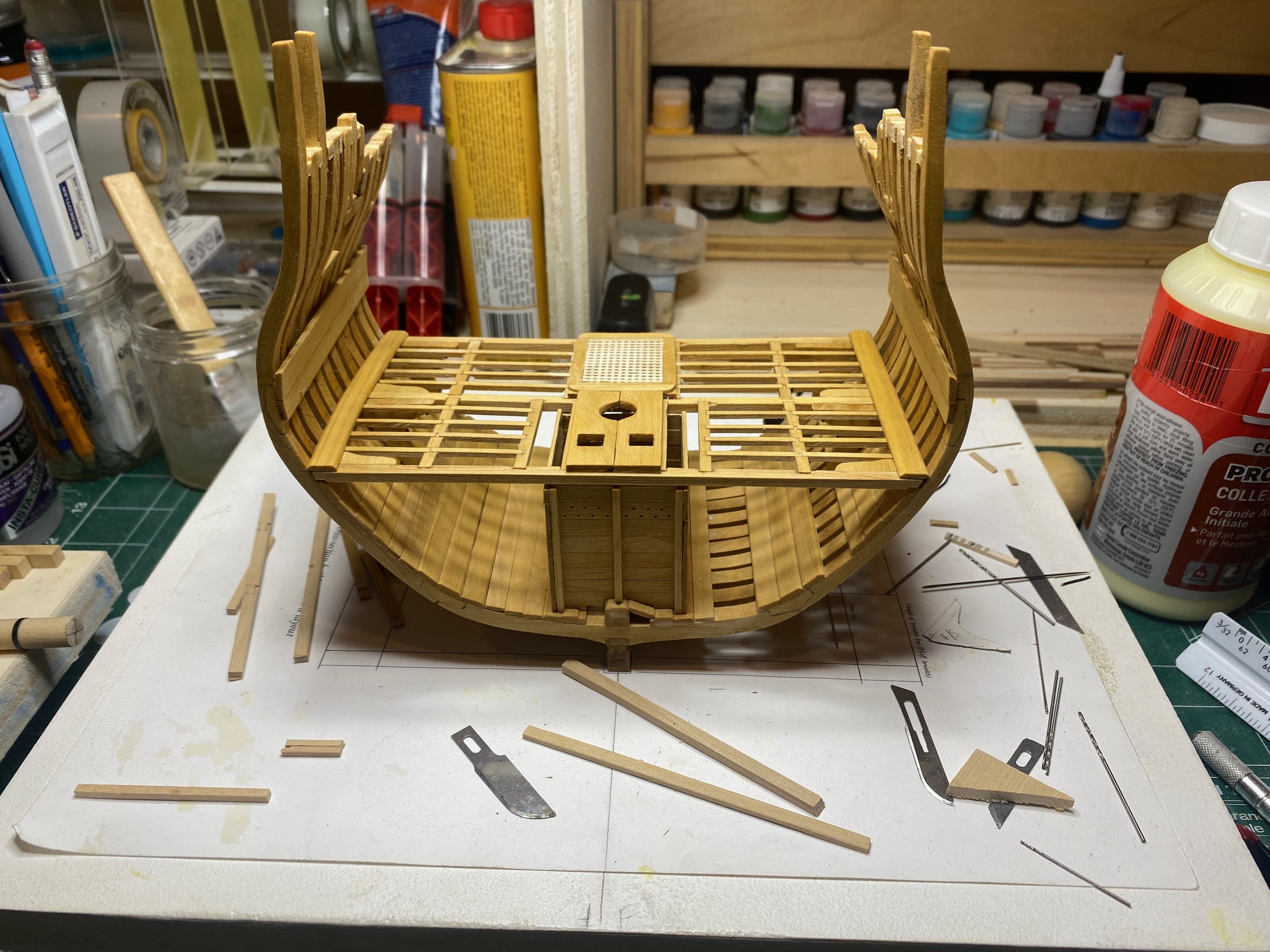
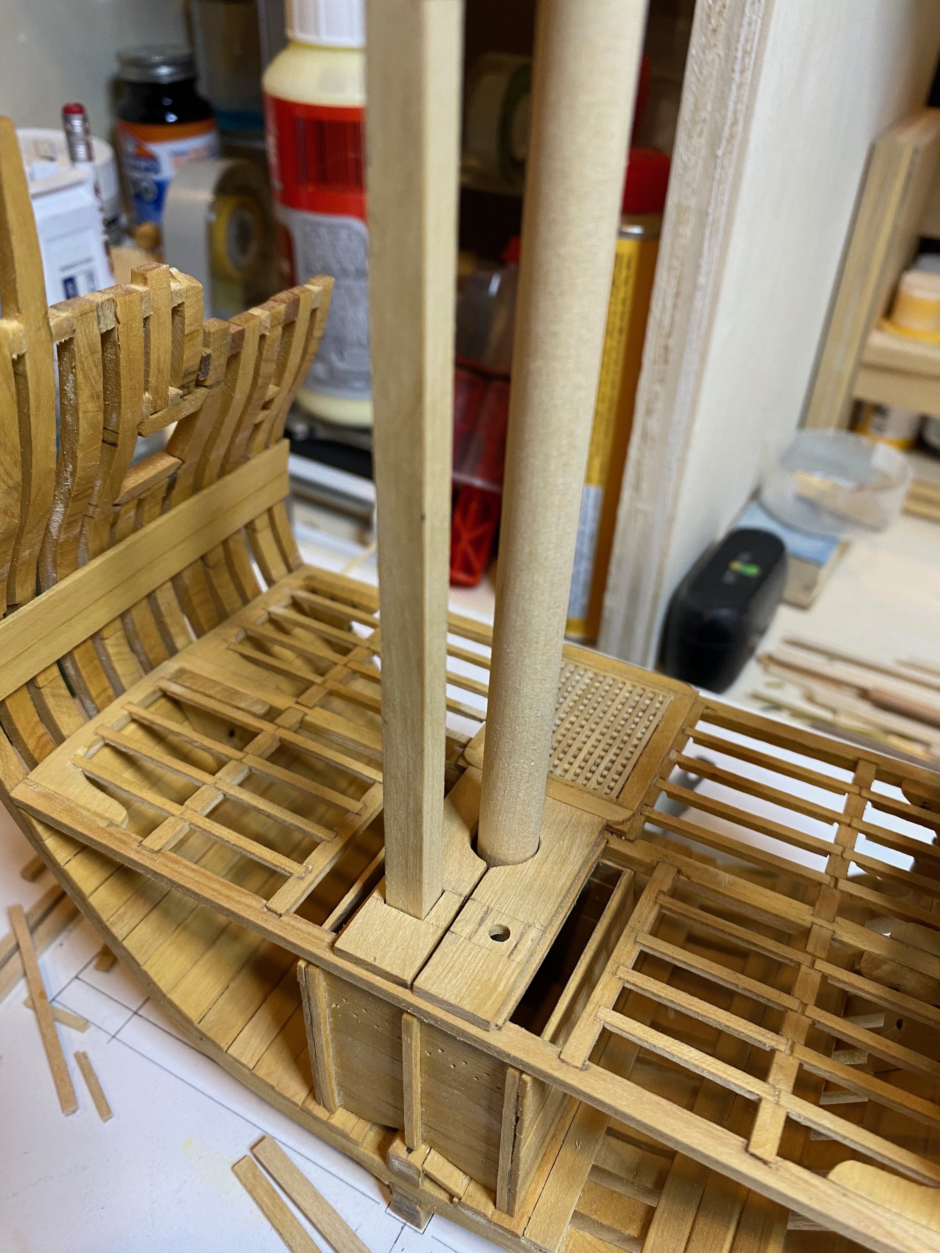
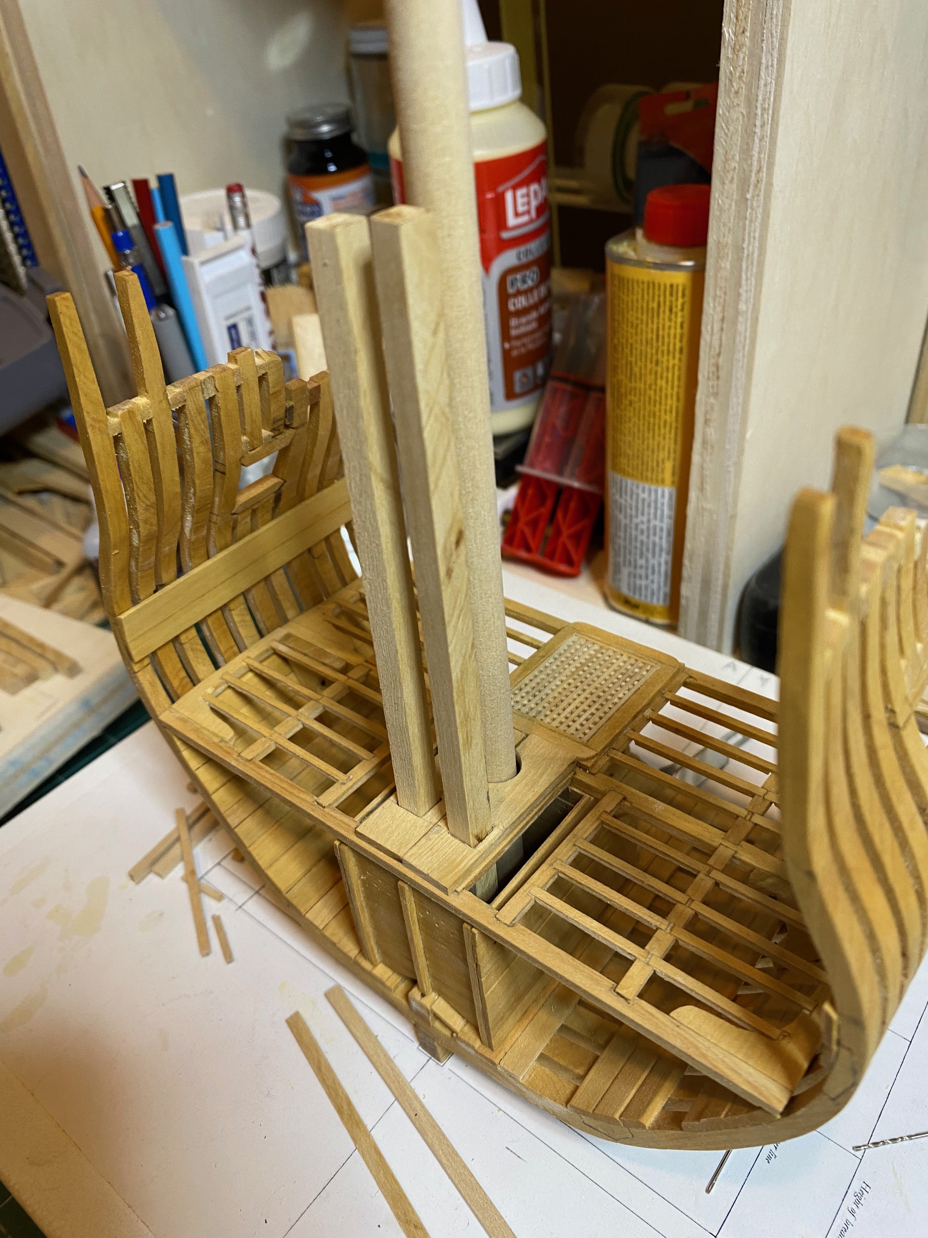
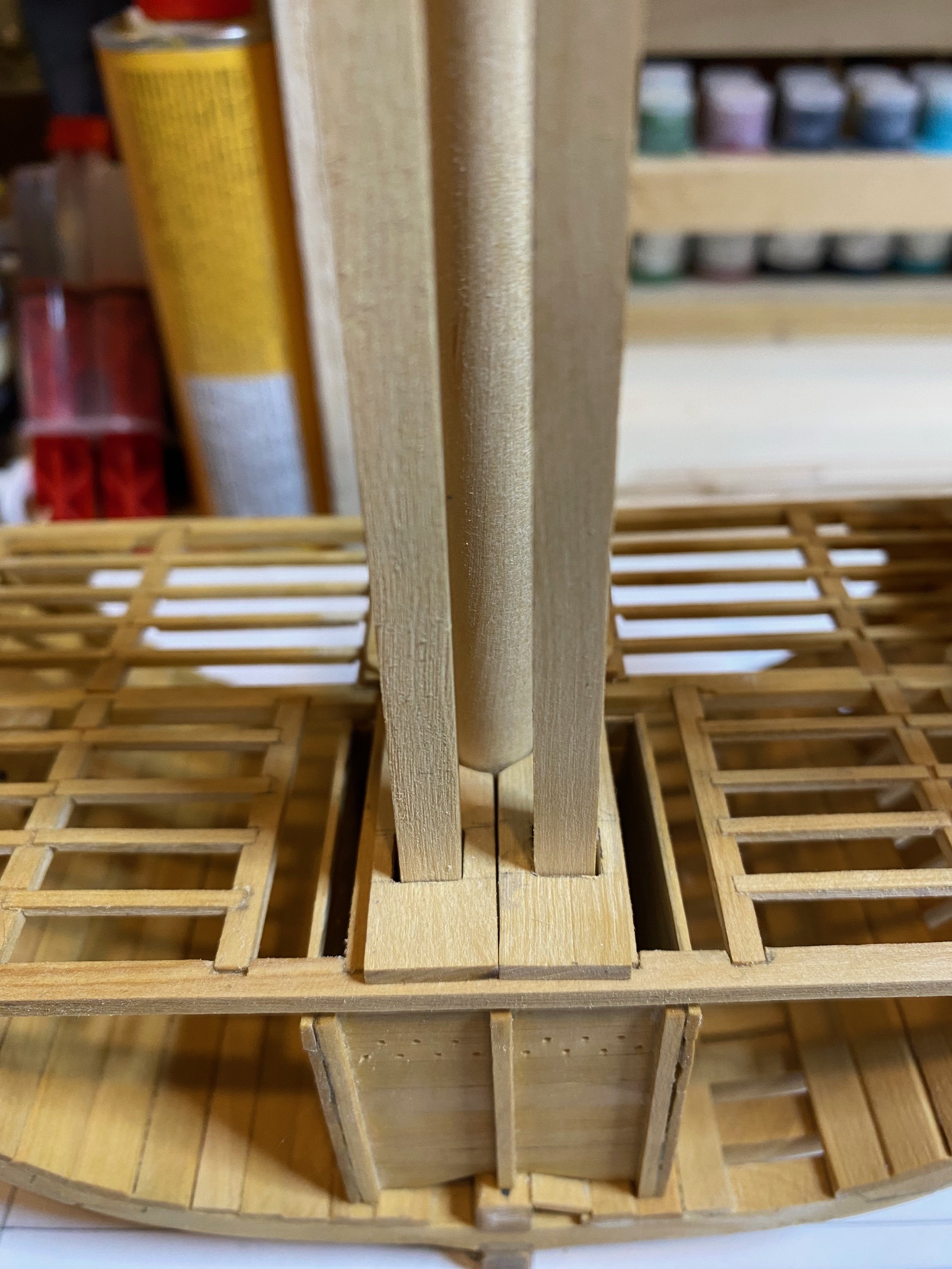
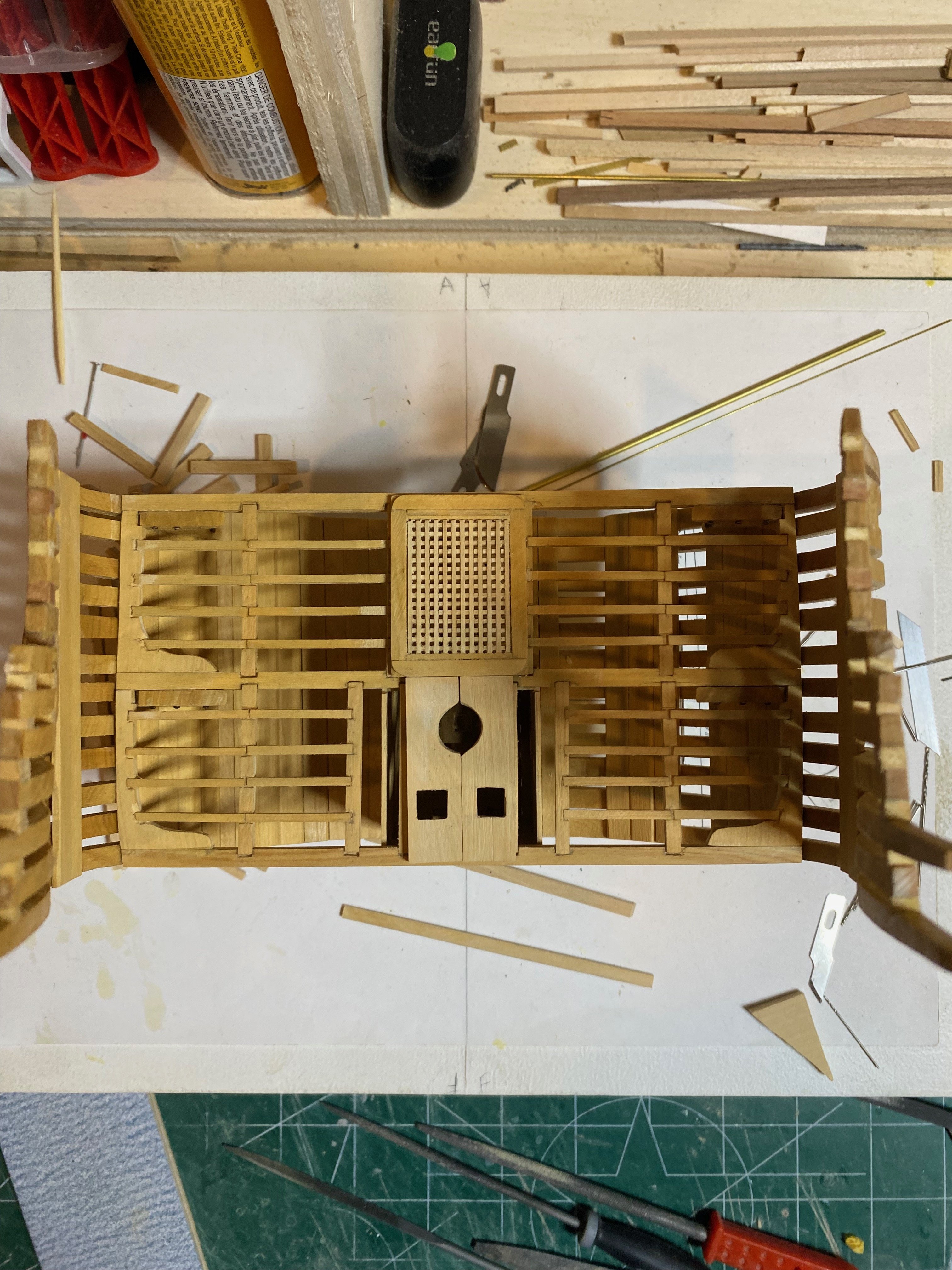
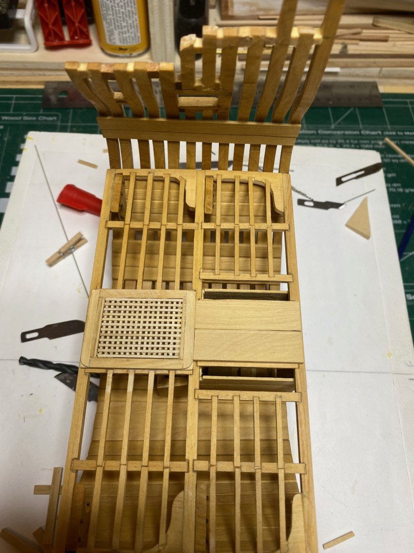
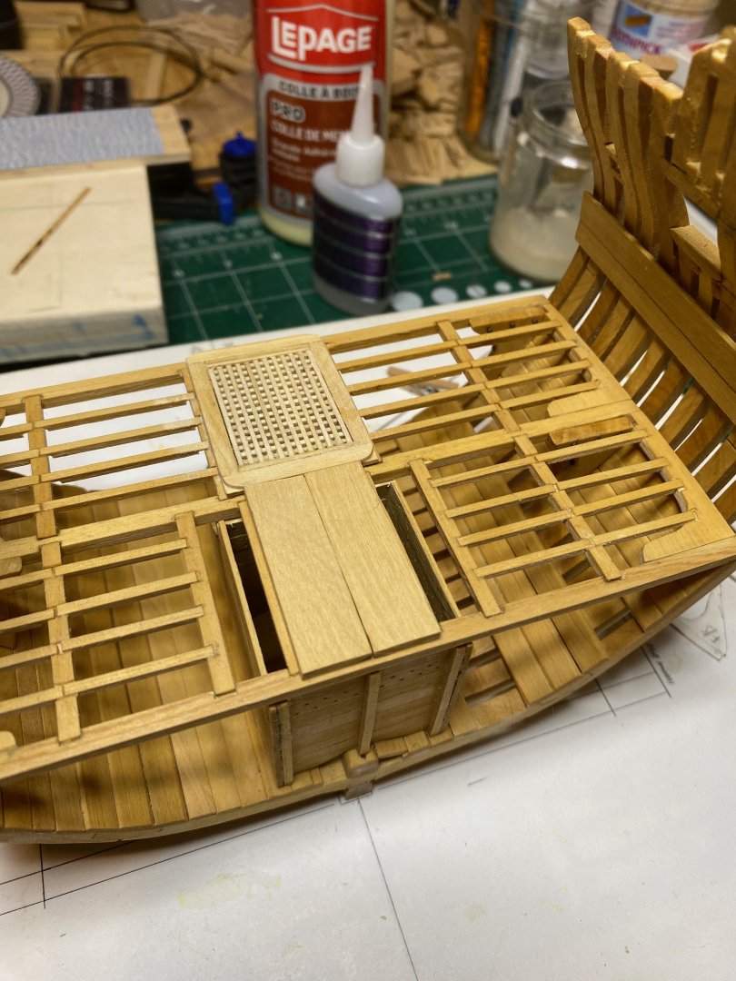
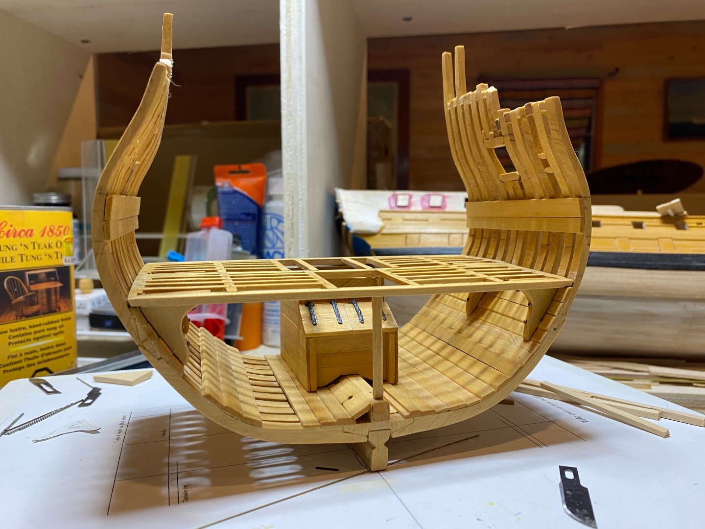
 After a longer-than-expected break, I managed to put some time in at the bench today, working on the lower deck planking. I realised that I had forgotten, when I installed the strakes around the mast partners and hatch, to file out a notch for the passage of the break pump shafts...so I lightly pried those pieces off and completed that step - truthfully, I broke one of the originals in this process and made a new one to replace it! I had milled a relatively small amount of 10" x 2" boxwood for the deck planks - only 7 strips total. So after installing the strakes around the hatch/partners, I had only 5 strakes. My plan is to lay only 3 strakes outboard of centre on the port side and full plank the starboard side - this alternates with the full planking of the inner hull on the port side and only partial planking there to starboard. I will also lay a binding strake along the inboard edge of the port side waterway - this will have to be spiled on the side laid against the waterway to account for the slight curvature on that side - noted above.... Quick question - were the lower deck planks trunnelled? Hope you're all doing well - happy modelling and enjoy the photos. hamilton
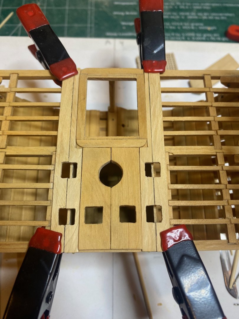


-
Looking good Harlequin! This kit seems more sensibly designed than Greyhound. Are the strips supplied for second planking narrower? The first planking strips seem very wide for the scale - though the planking work itself is very good! hamilton
-
In the most famous version of the painting, Icarus is just a pair of legs sticking out of the water - typical Breughel humour! There is another version of the painting floating around that also shows Daedalus flying off in the distance...that would be much harder to render realistically! The model looks really nice! As small as it is, it has a grandness to it. hamilton
-
One of my favourite paintings of all time and the subject of a lecture I give on technology and ethics - will be nice to see that lovely ship come off the canvas! hamilton
-
Following the prototyping process is such a treat!! Thanks for sharing this with us Chris!! Does way more than build excitement for this kit! hamilton
-
I think you're doing a great job with this build - despite the noted deficiencies of this kit!! Peace be with you too! hamilton
-
Juts catching up here - the decking looks great! hamilton
-
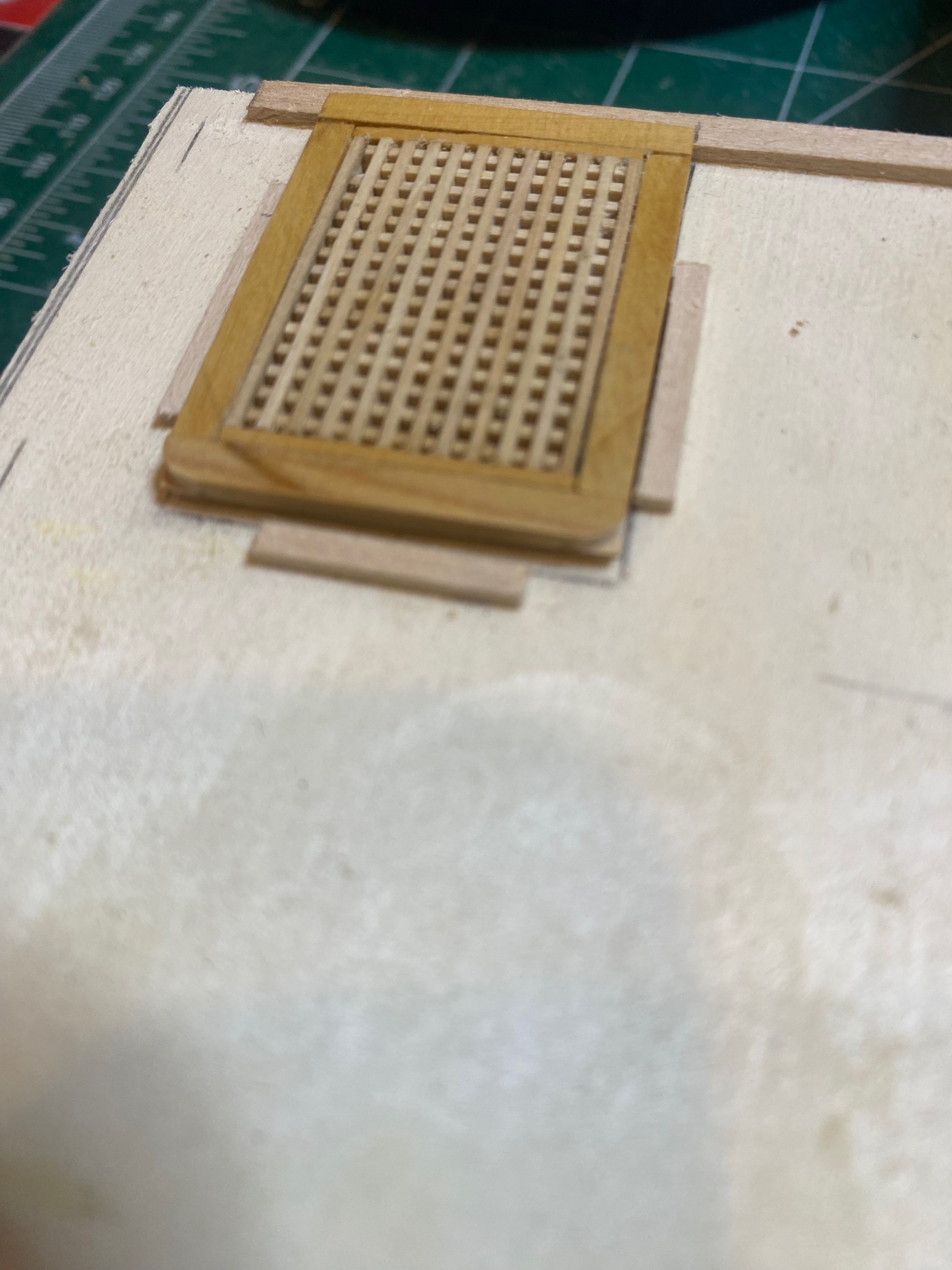
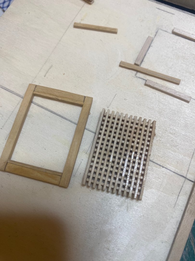
Yes - that's true - the gratings were pirated from my Syren kit and they were slightly short of the correct length, so I had to add some padding on the fore/aft inside edges of the head ledges...so those are too wide - the coamings port and starboard are 6" x 4" as noted in the practicum...Buth the head ledges ended up at 7.5" instead of 6.....next time I will make my own gratings to size - I was just cutting corners...not good modelling practice, but..... hamilton
-
A small update on Echo. I've made and installed the spirketing plank above the lower deck waterways on the starboard side. As noted above, the port side is asymmetrical to the starboard and the waterway curves inboard as it runs aft. I made a spirketing for the port side, but this curved waterway means that I need to sculpt the plank a little bit more than was the case with the starboard side....I'm considering not planking the port side lower deck to avoid this....and rationalising this choice by deciding to alternate the full planking port and starboard...anyways, there's lots of time to make decisions... I also started the lower deck planking - beginning with the strakes just outboard of the hatch/mast partners. These have to be notched around the hatch, which is wider than the partners, and a notch needs to be cut in for the passage of the outboard chain pump shafts. I marked these cut-aways out and removed the wood on the scroll saw, cleaning them up with some needle files after. I will be planking the deck fully on the starboard side, but will only install one or two other strakes outside of the currently laid one on the port side. These planks are as yet unfinished - a light sanding and sealing will happen once all the deck planks are in place. Happy modelling and bye for now hamilton


-
Managed to get a few more hours in the workshop this afternoon and made/installed the lower deck waterways. These were relatively straightforward, though I had to take time to mill a 3" sheet of boxwood. I then discovered that there is a bit of asymmetry in the frames, as there is a noticeable wasting aft on the port side but this is more subtle on the starboard side - this means that the port side waterway is slightly curved in shape while the starboard side is more or less straight.....this is teaching me a lesson for the next time I try something like this. In any case the waterways were chamfered on the outboards lower edge to fit nicely against the frames, as well as on the outboard upper edge to fit the spirketing (which is next up on the list). The plans show them reducing to 2" to meet the deck planking - I simplified this by chamfering off the inboard upper corner at as oblique an angle as I dared - not perfect and not reflective of actual practice, but.....I'm keeping a list of things that I need to work on more rigorously next time..... Enjoy the photos and bye for now hamilton


-
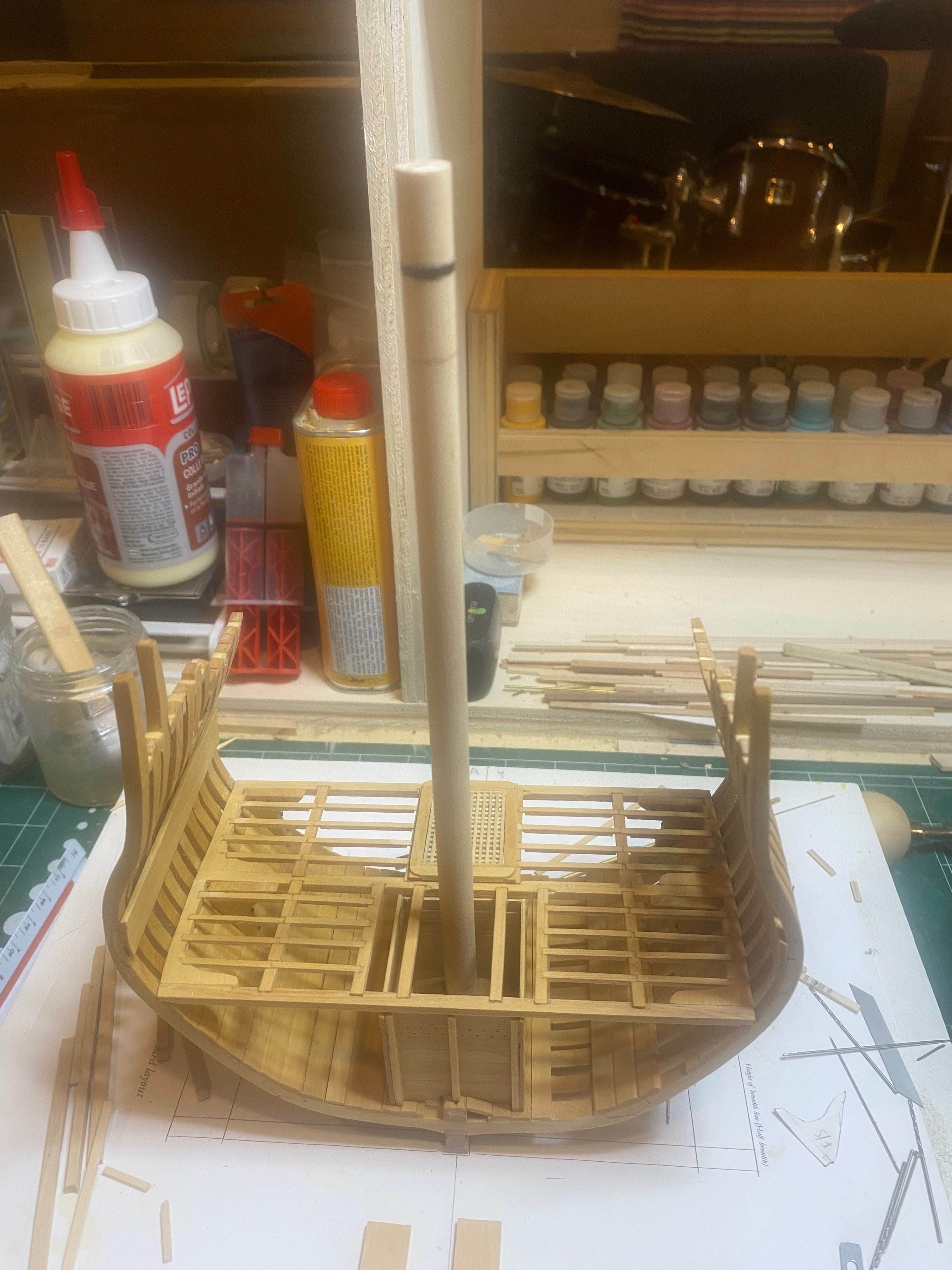
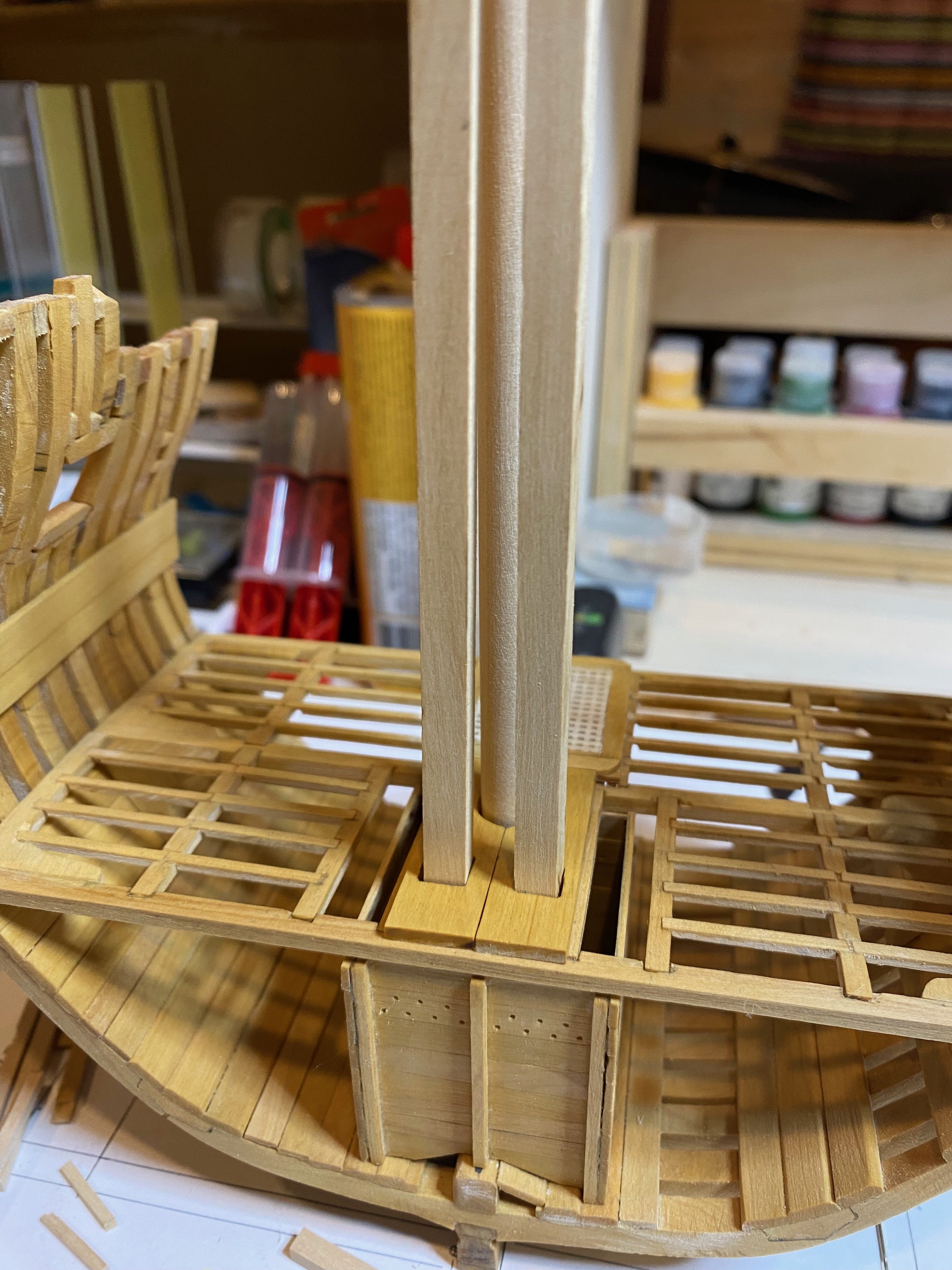
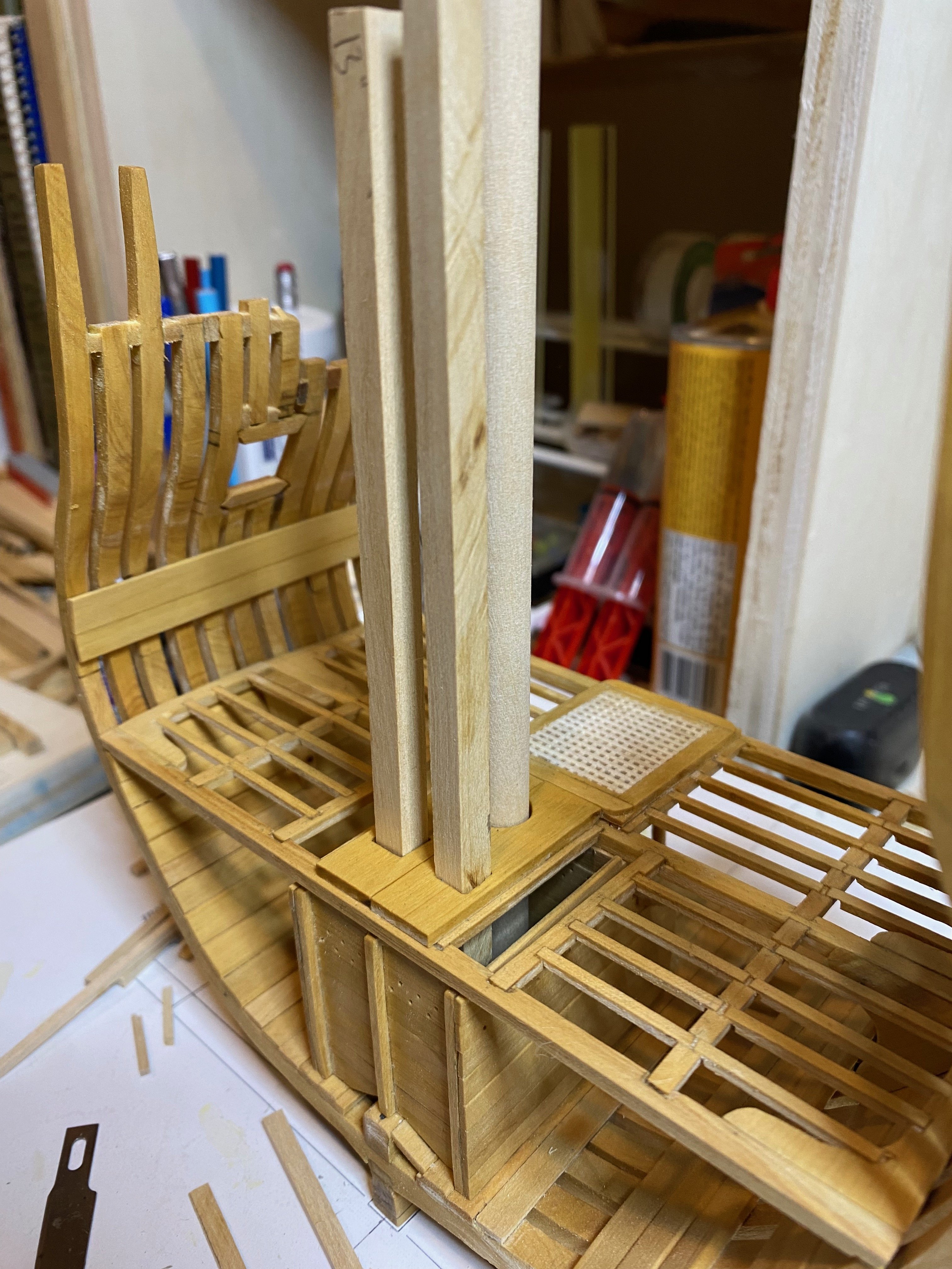
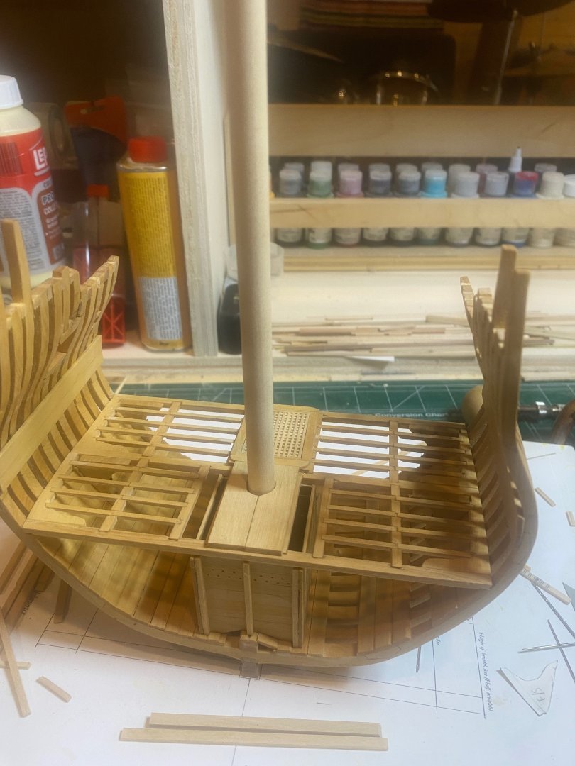
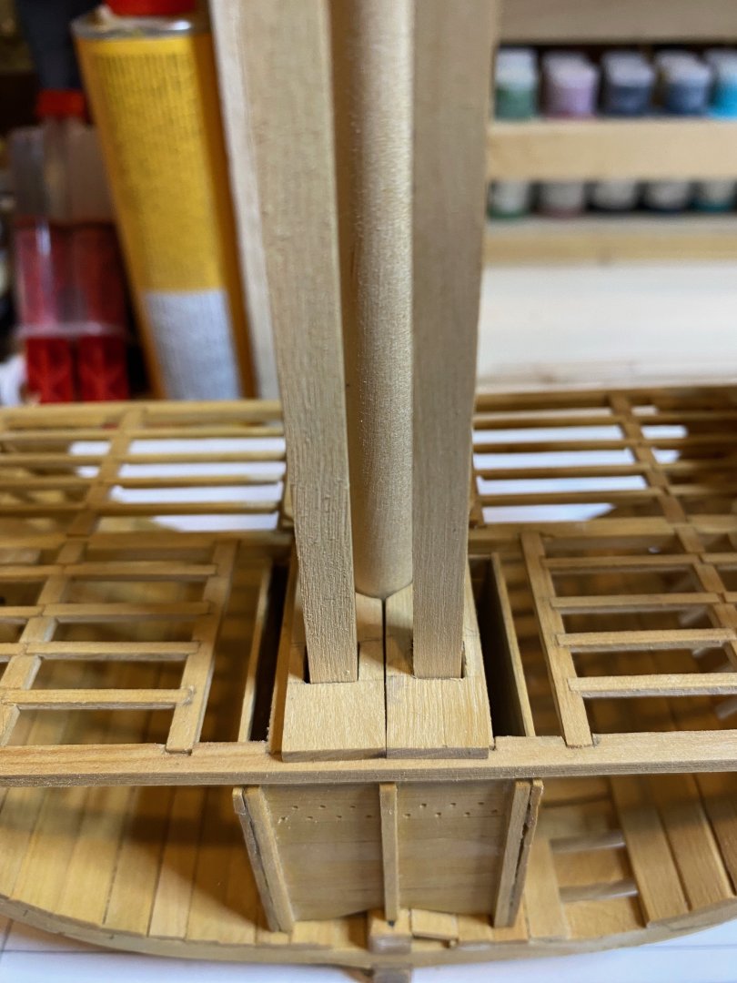
Well it's been way longer than I had hoped, but work has been busier than usual and so I haven't been able to clock any time in the workshop until today. The morning saw the completion of the lower deck mast partners. This involved first cutting a dowel to serve as a blank for the main mast, cutting a tenon into the lower part to fit into the step and then dry fitting that to get the position of the mast hole in the partners. I used a combination of round and half-round files as well as the dremel tool for finishing. The hole is not entirely even, but this will not be very visible in the end, so I'm not too concerned. Marking, drilling and filing out the square holes for the chain pump shafts followed a similar process. I already milled a bunch of 11" square stock for the pump shafts and, using two of these, I marked them out on the partners. Small holes were drilled on the drill press and then widened and squared using an assortment of files. The partners were then installed permanently on the deck framing. Next step will be to make the lower deck waterways and spirketing planks, and then lay the deck planking. I'll fully plank the port side and leave part of the deck framing exposed to starboard. During the planking, I'll also have to consider the run of the return shafts of the chain pumps....but that's for later. In the meantime, here are some photos. Enjoy and happy modelling hamilton


-
Thanks Benjamin - there were definitely a few hiccups in the build - let me know if you hit any snags and I might be able to provide some useful advice hamilton
-
The second photo shows the way the plans came for me when I ordered them, so this is not atypical. I did not find this an issue when making the bulkheads, since I always made sure to take tracings from the plans of each of the parts I needed to manufacture - specifically the keel pieces and bulkheads. If you invest in some carbon paper, tracing paper and card paper you can make multiple templates of each part - for my own part I know I made the keel pieces three times and the bulkheads at least twice (some three)....if you trace them off the plans, you just focus on one area of the plans at a time and ensure that they are not too awkward to work around those folds....fortunately, they're not hard folds so with a bit of weight on them they should be fine to use.... Good luck with the build - I'll follow with interest hamilton
-
Beautiful results as always, Yves - so nice to see her out of the cradle - you really get a sense of the sleek lines - a great looking model! hamilton
-
I imagine many of us are familiar with that feeling! hamilton
-
The ironies of ship modelling.....from the photo any imperfections are completely invisible! hamilton
-
USS Constitution by mtbediz - 1:76
hamilton replied to mtbediz's topic in - Build logs for subjects built 1751 - 1800
Wow - that really holds up to scrutiny! hamilton -
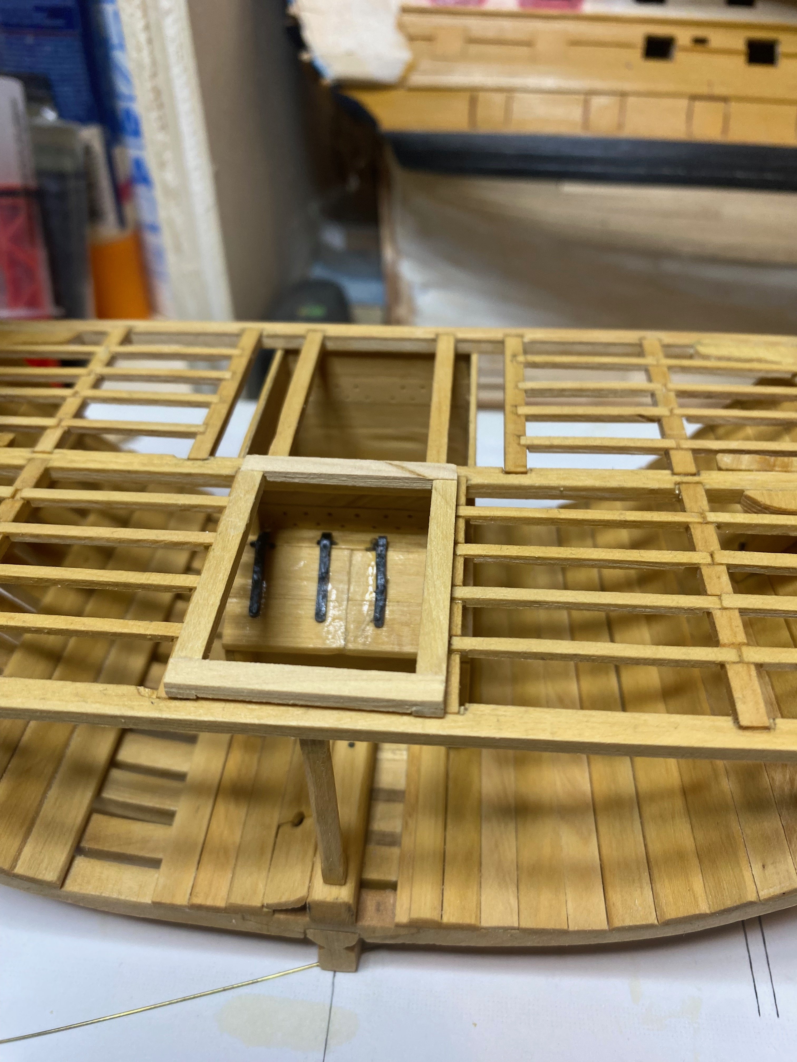
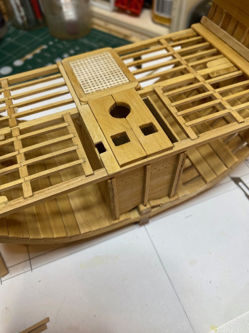
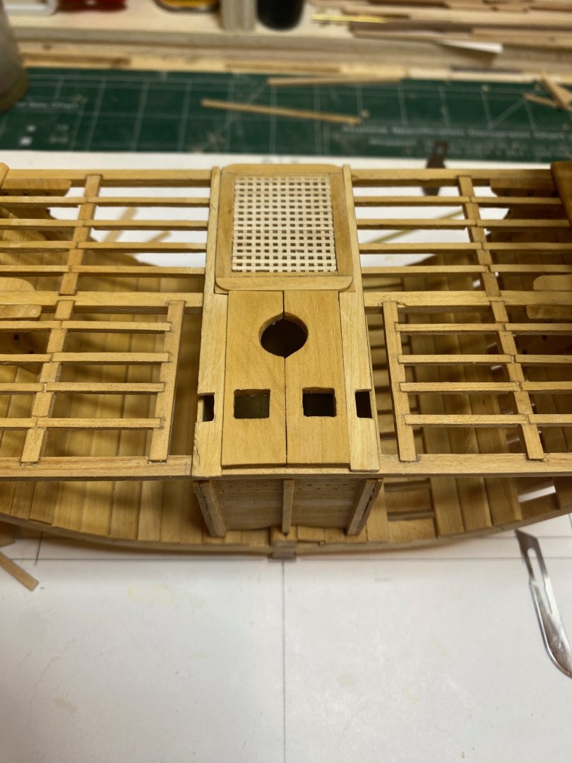
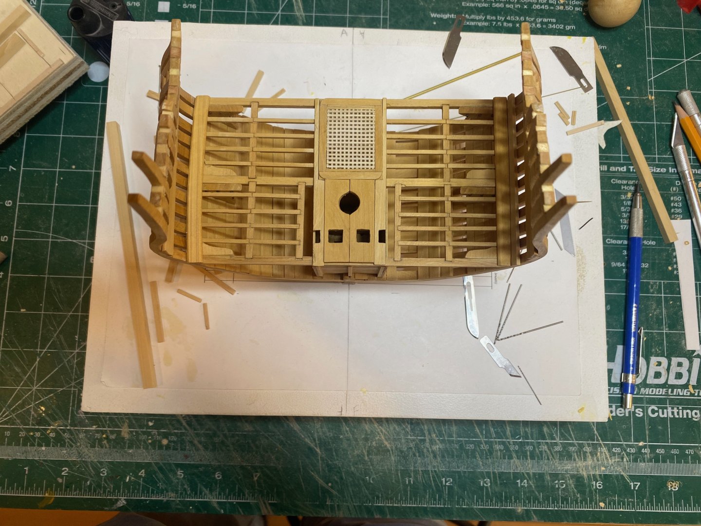
After spending a week looking at the lower hatch, I found myself becoming increasingly dissatisfied with it. So today I rebuilt it. The most difficult part of this was prying the old one off the model - I used a micro saw for this and worked very slowly and gently until it came loose. Sanding down the deck framing and re-applying some wipe-on poly made it look fine - a couple of blemishes, but these are hidden by the hatch itself, so not a big deal. The blanks for the partners are obviously just dry fit for now - lots of work to do on those before they're ready to be installed! It's still not perfect, but I think it looks much cleaner than the last one. I had intended to spend today milling the pump shafts, making a mast dummy and starting work on the lower mast partners, but that now is put off to a later time..... I hope to be able to find some time in the workshop this coming week - work is in a very temporary lull until the week after next, when we have our spring break at the university - a time for the kids to go to the beach and the grown-ups to mark mid-term assignments.....fortunately I'll be doing that at my parents place in the woods of eastern Ontario with a decent supply of beer and cookies (obviously not consumed together!). Enjoy the photos and bye for now. hamilton
-
Such a nice sleek hull... hamilton
-
Just came across your build log - I've not seen anyone build this one (though maybe there's a log or two in the archive here...) - very exciting to see!! The work looks good so far hamilton
-
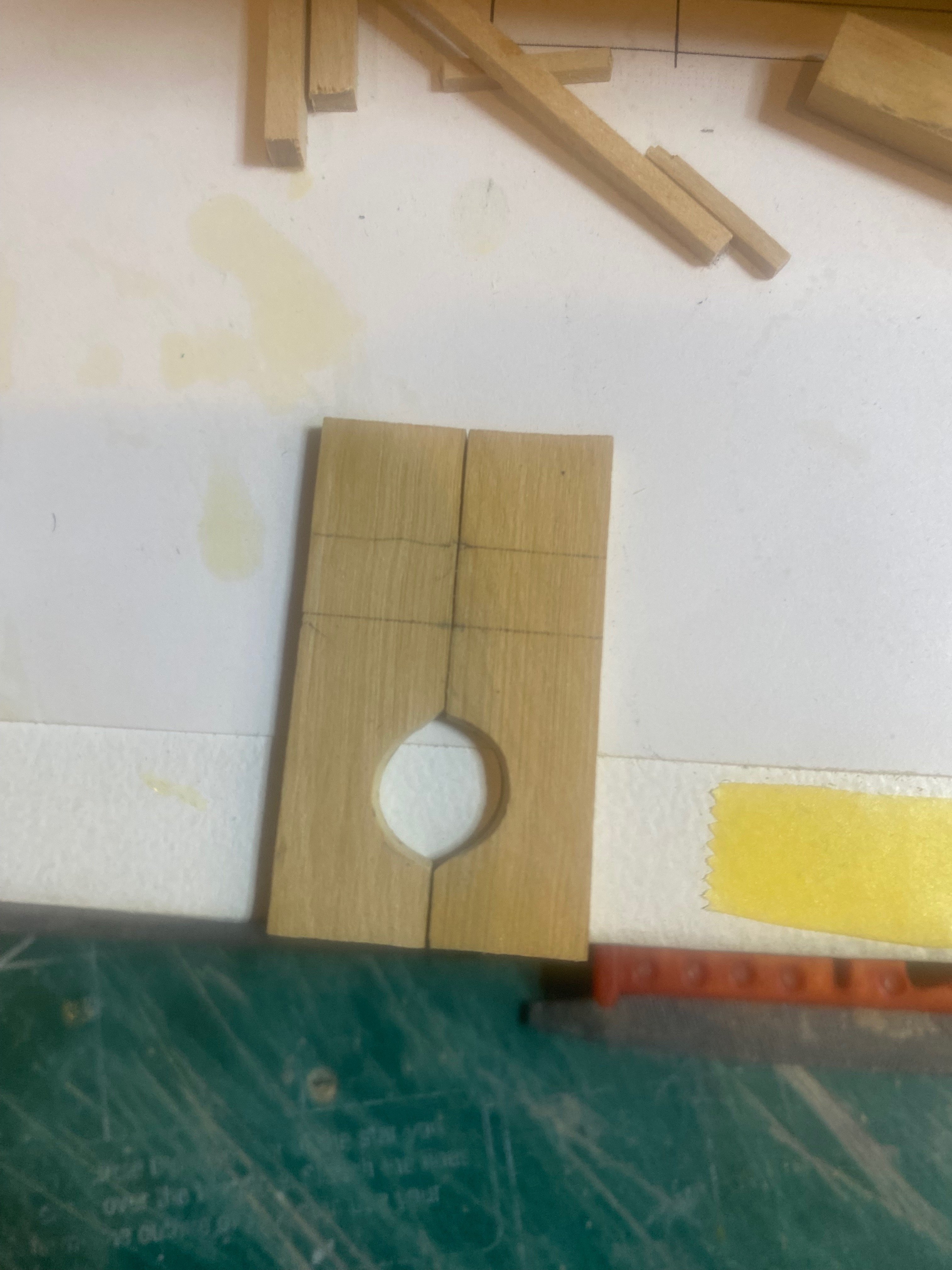
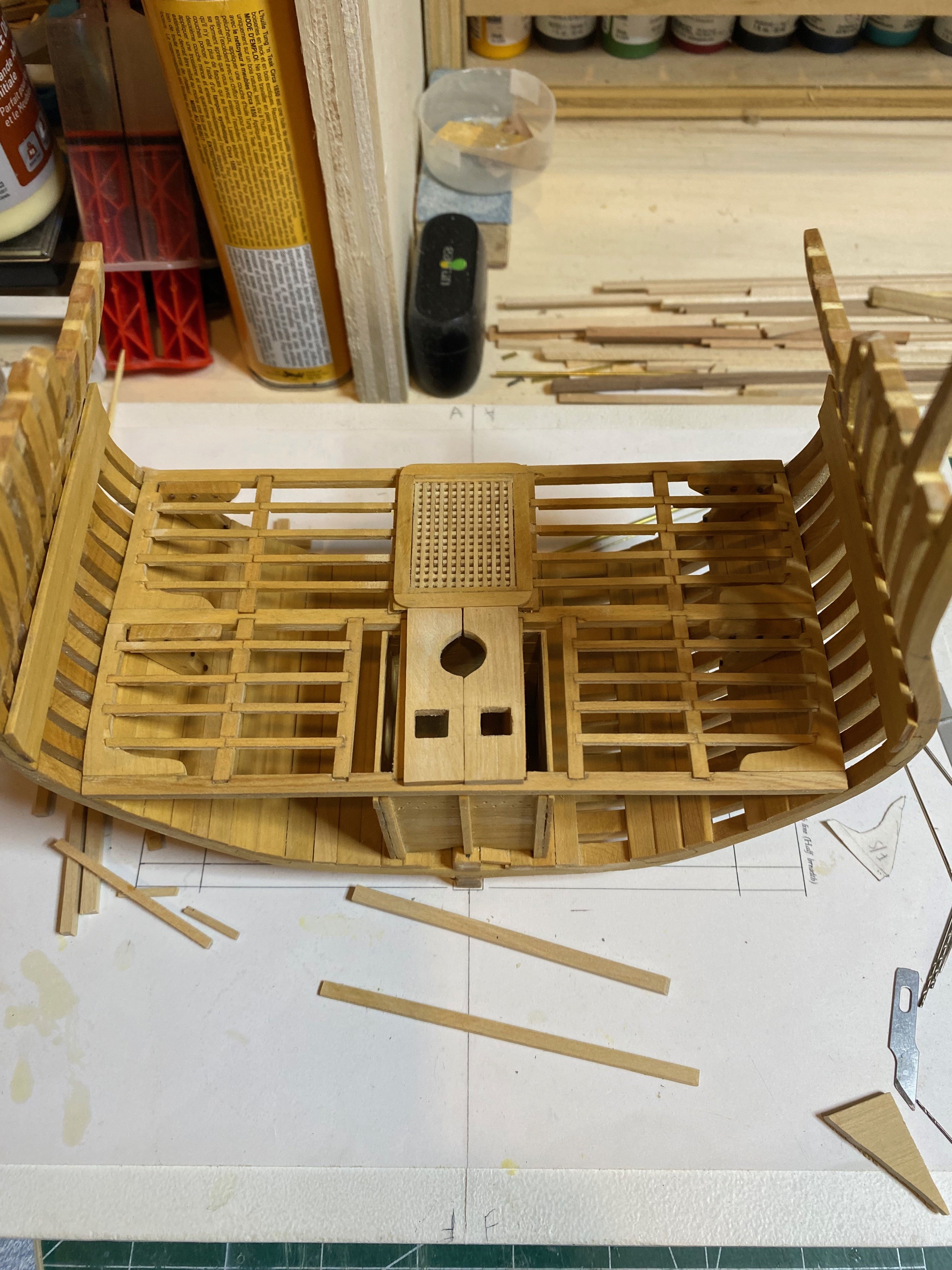
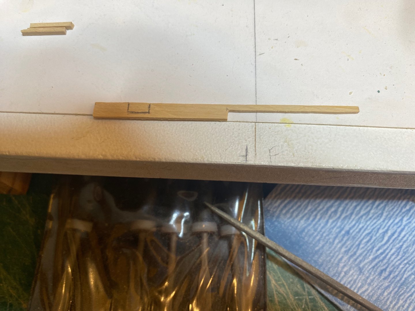
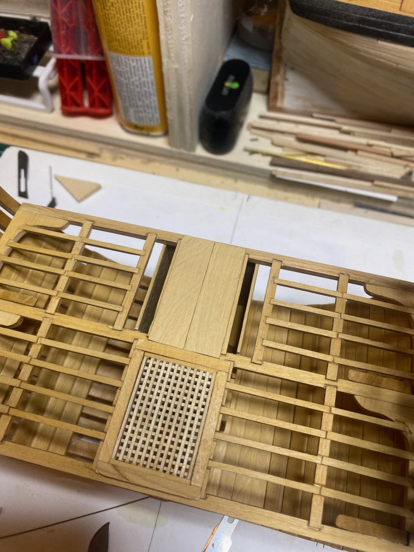
Small update...realised that I forgot to round the upper corners of the lower hatch coamings and headrails, which I did this evening - had to lightly pry the part off the model, but this was not too tough. To do this, I placed the part into the holding jig I made for its initial assembly, then ran a #11 blade horizontally at the corners - the battens defining the jig are at roughly 2" (at scale) so the perfect level to the rounded portion of the coamings which stands proud of the 2" planking. I also milled a small piece of 4" thick (at scale) boxwood and made two small blanks for the two halves of the lower mast partners. I cut a card template to the full dimensions of the partners, divided this with a centreline, and then used that to cut out the halves - which you see below dry fit in place. There is a lot of work to do on these - and some other things to work out in process - before they can be installed. Happy modelling and bye for now hamilton

-
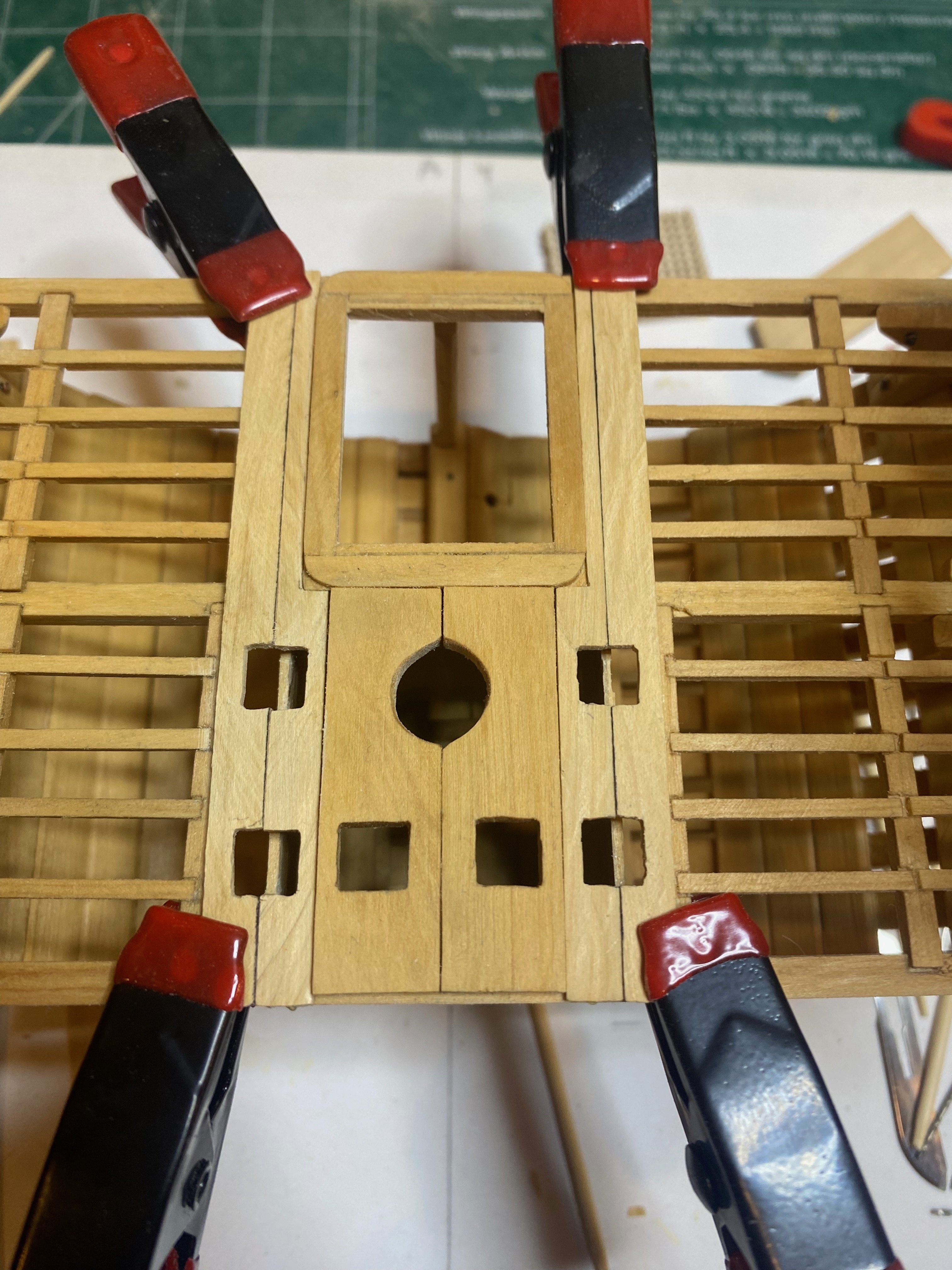
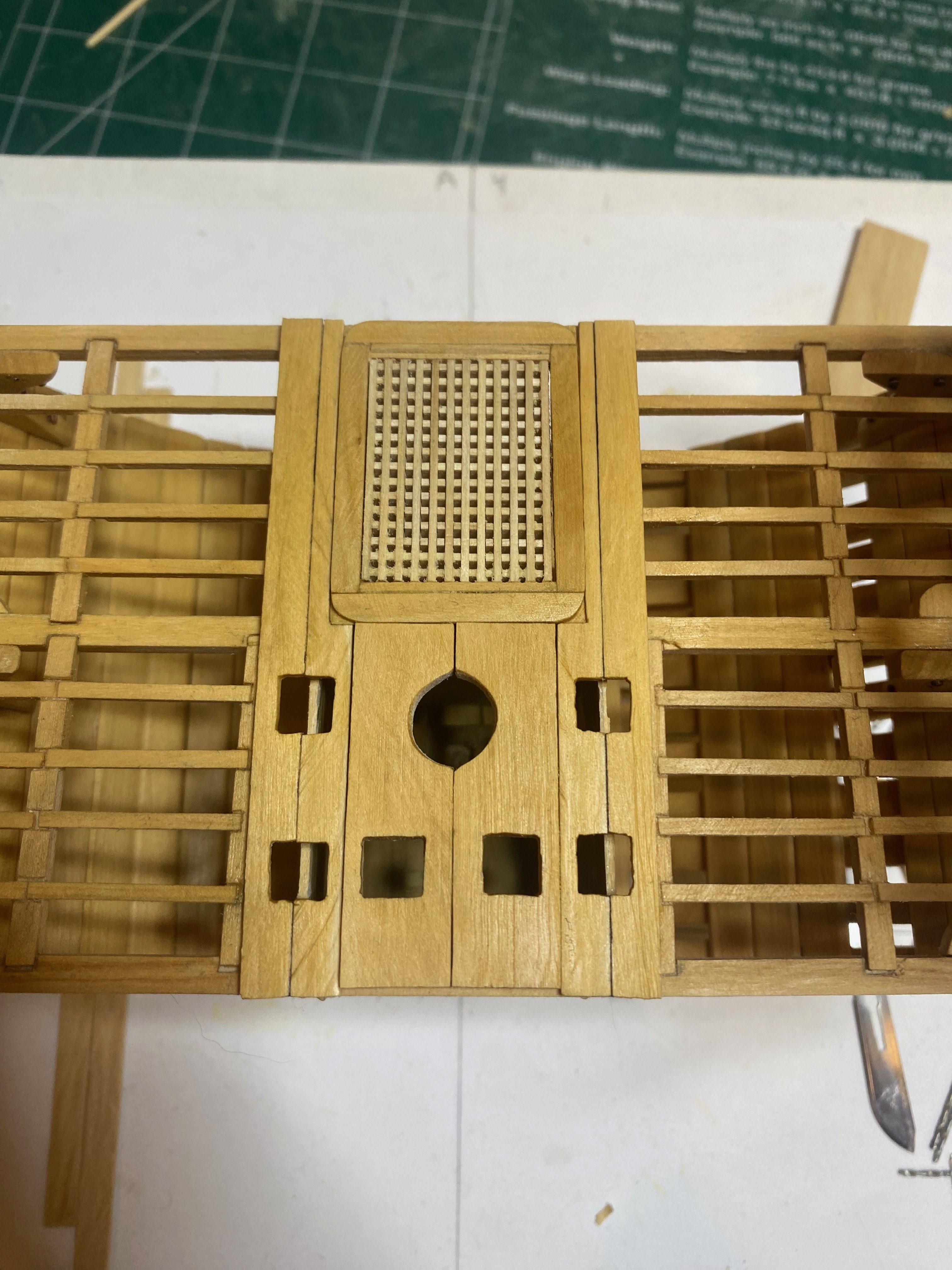
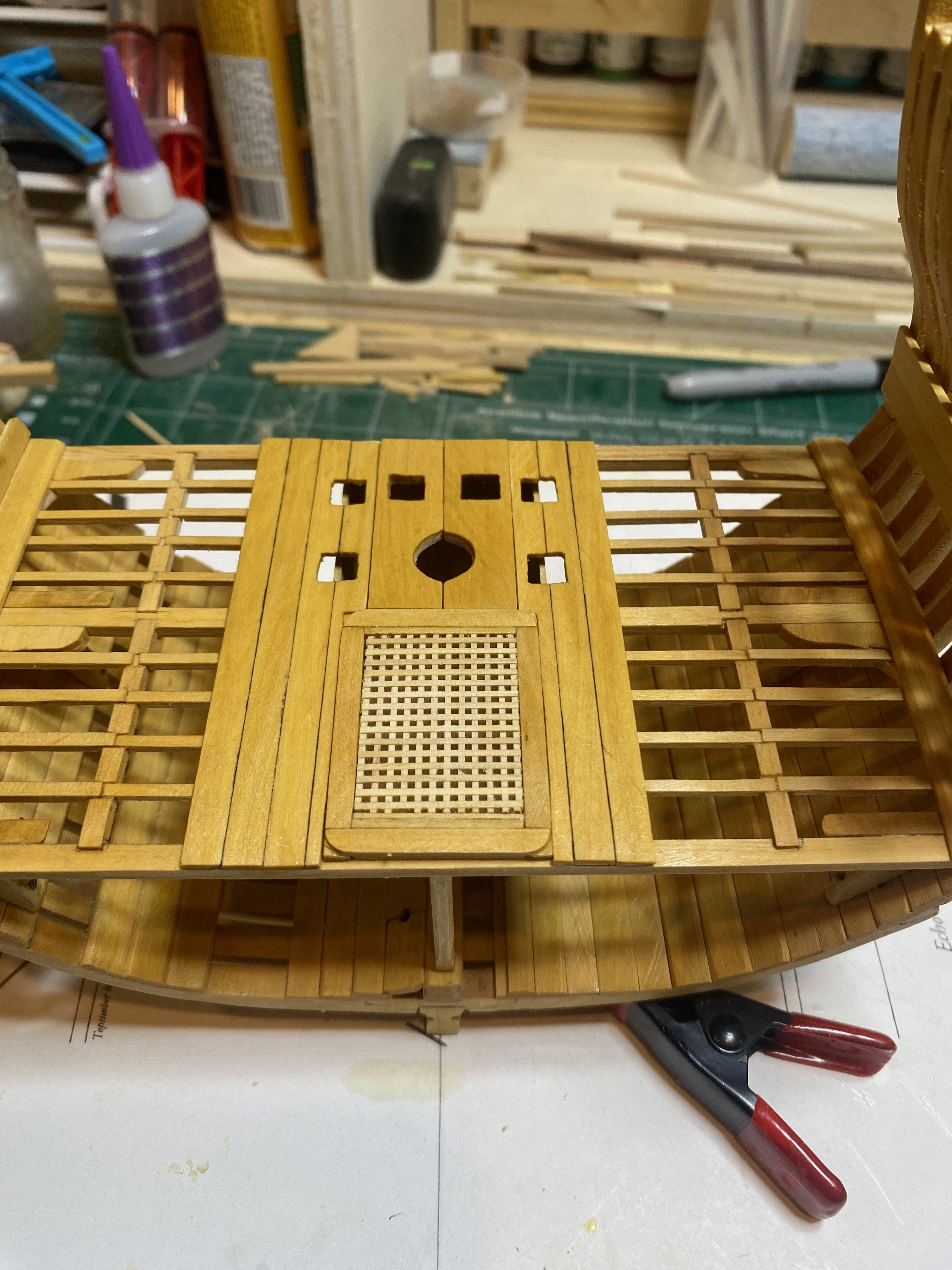
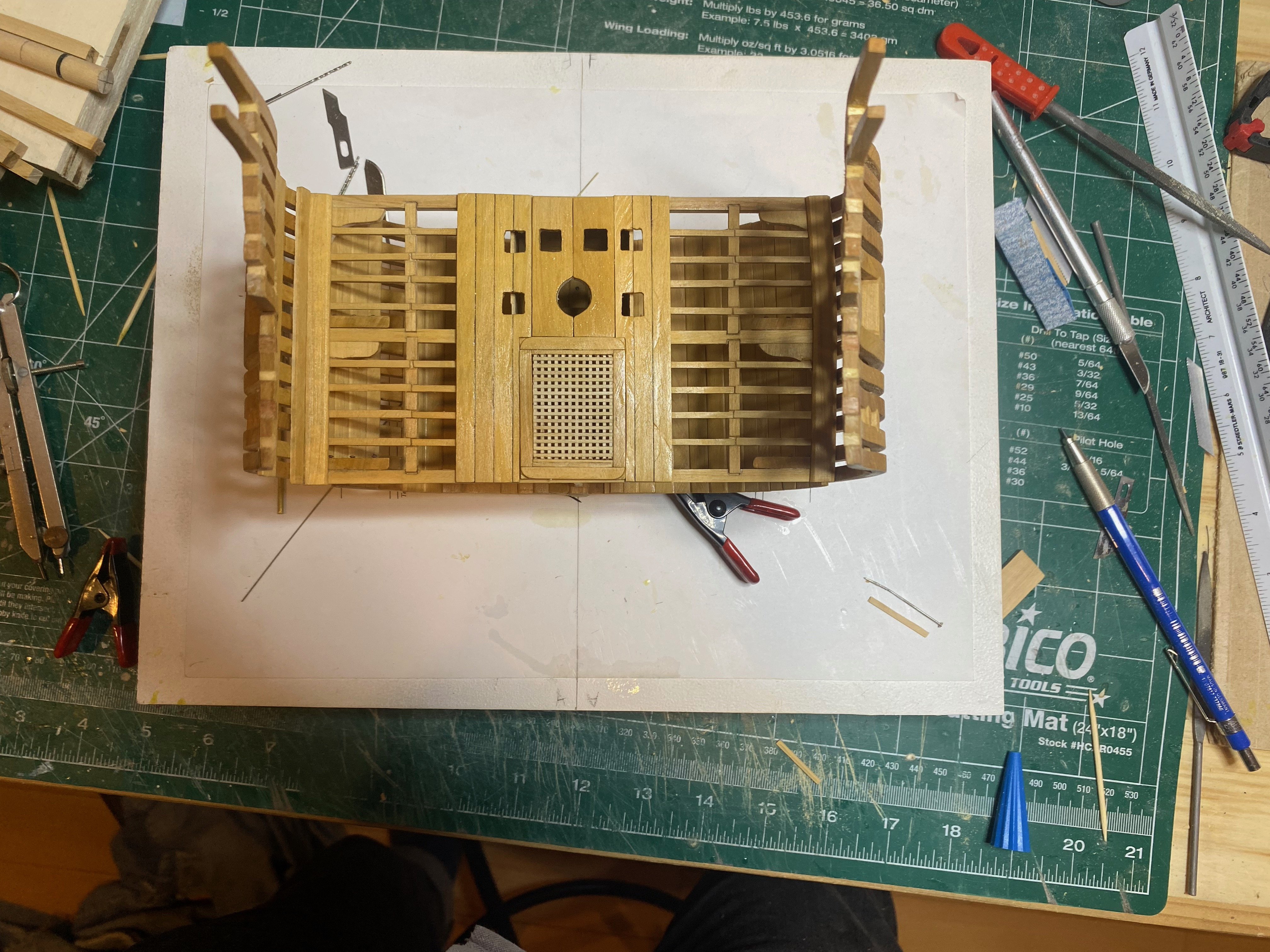
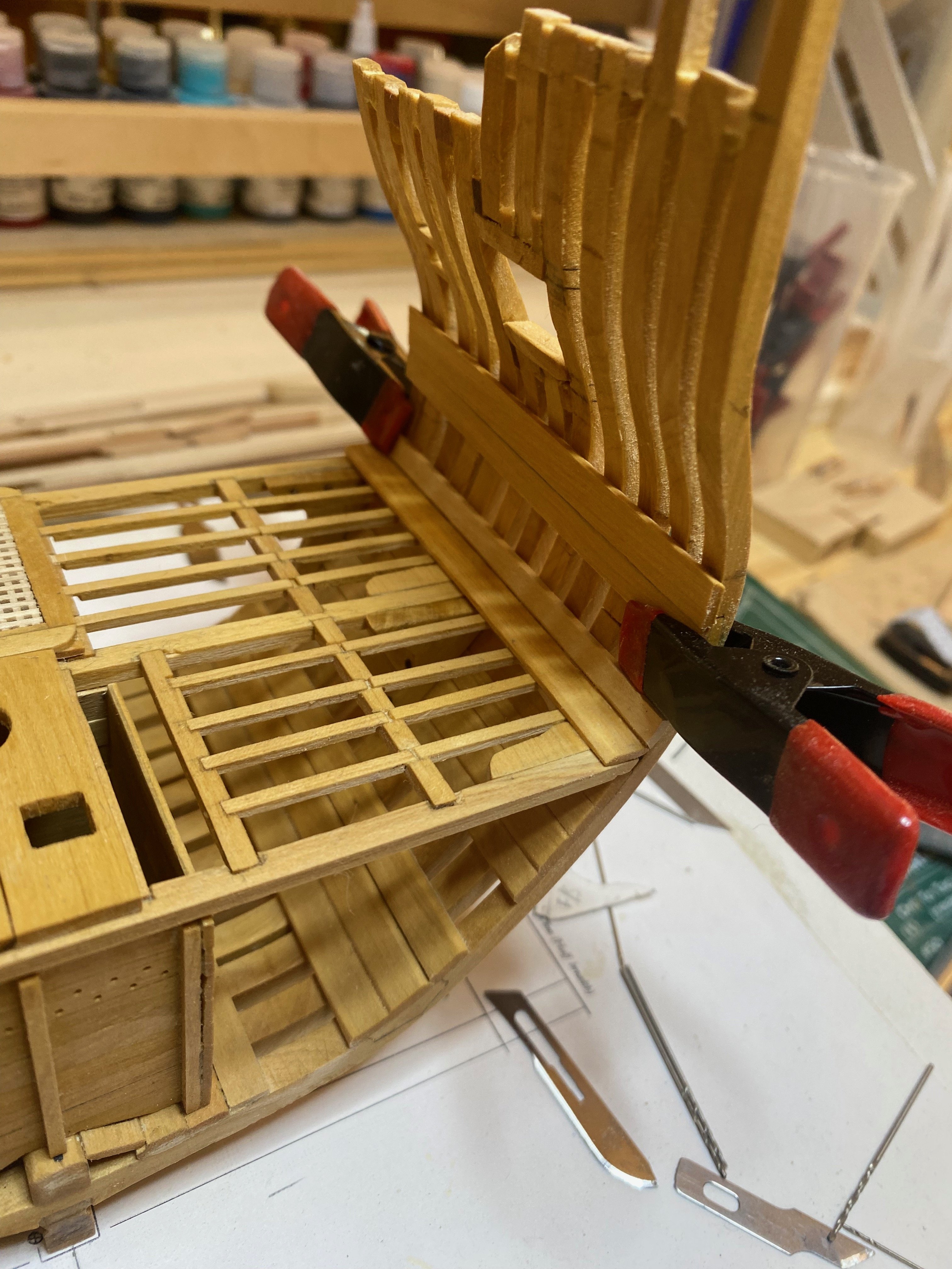
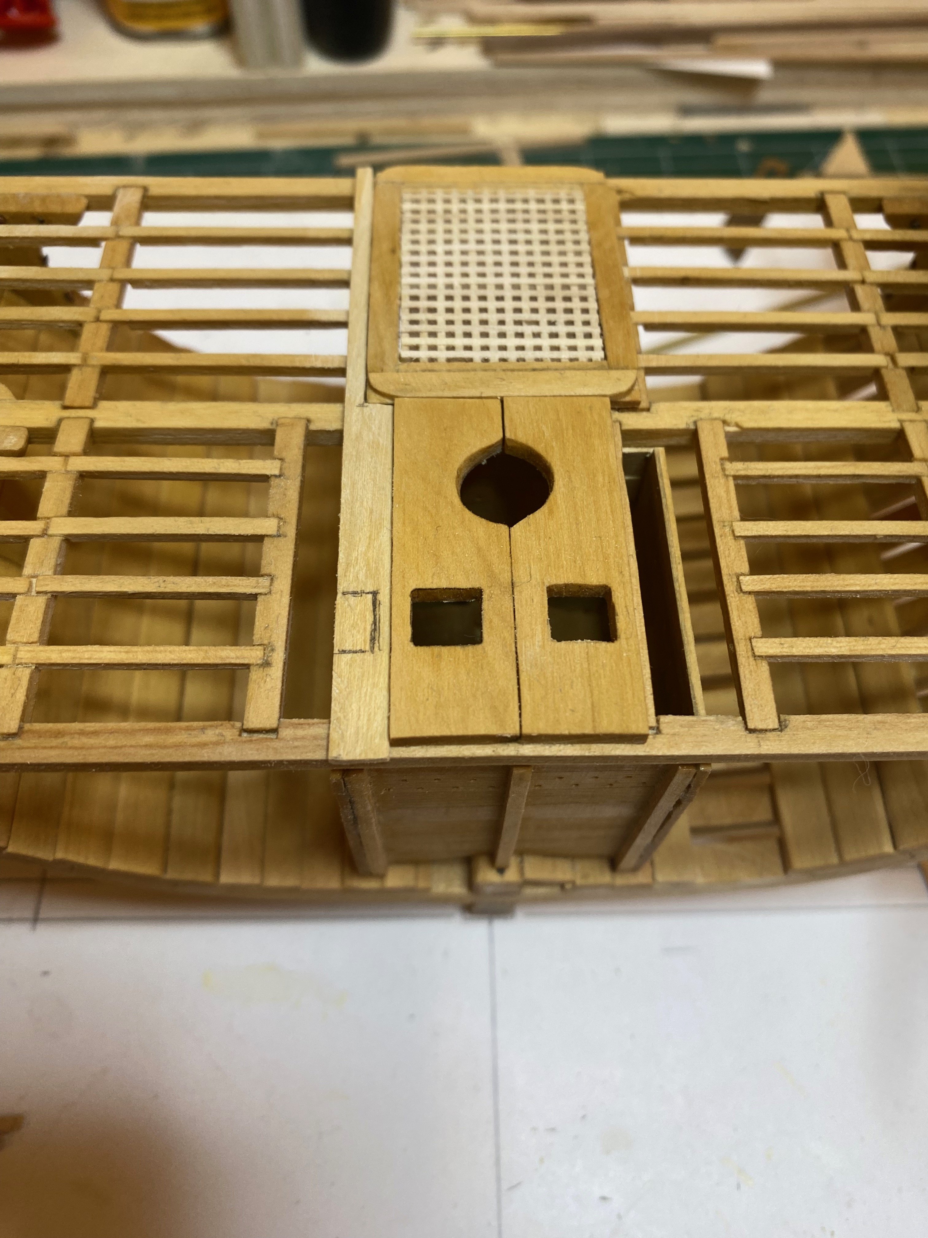
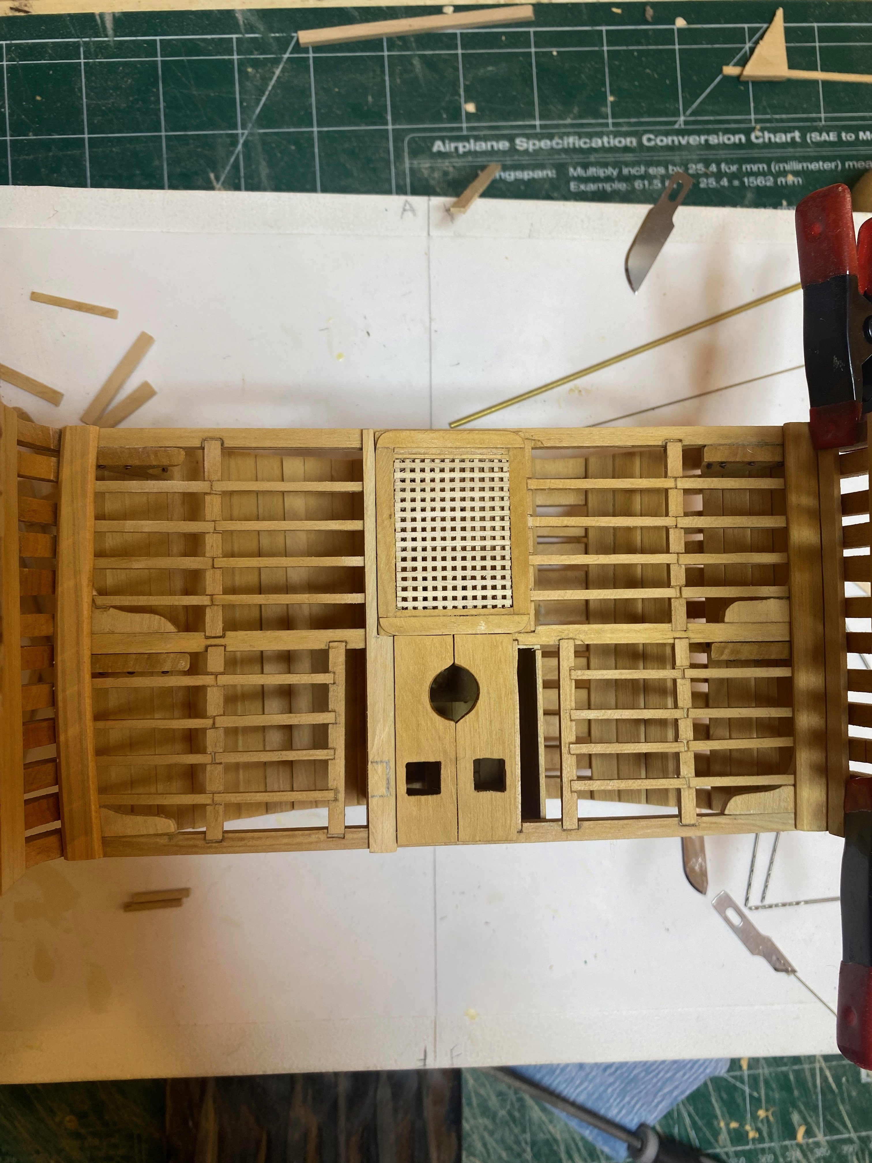
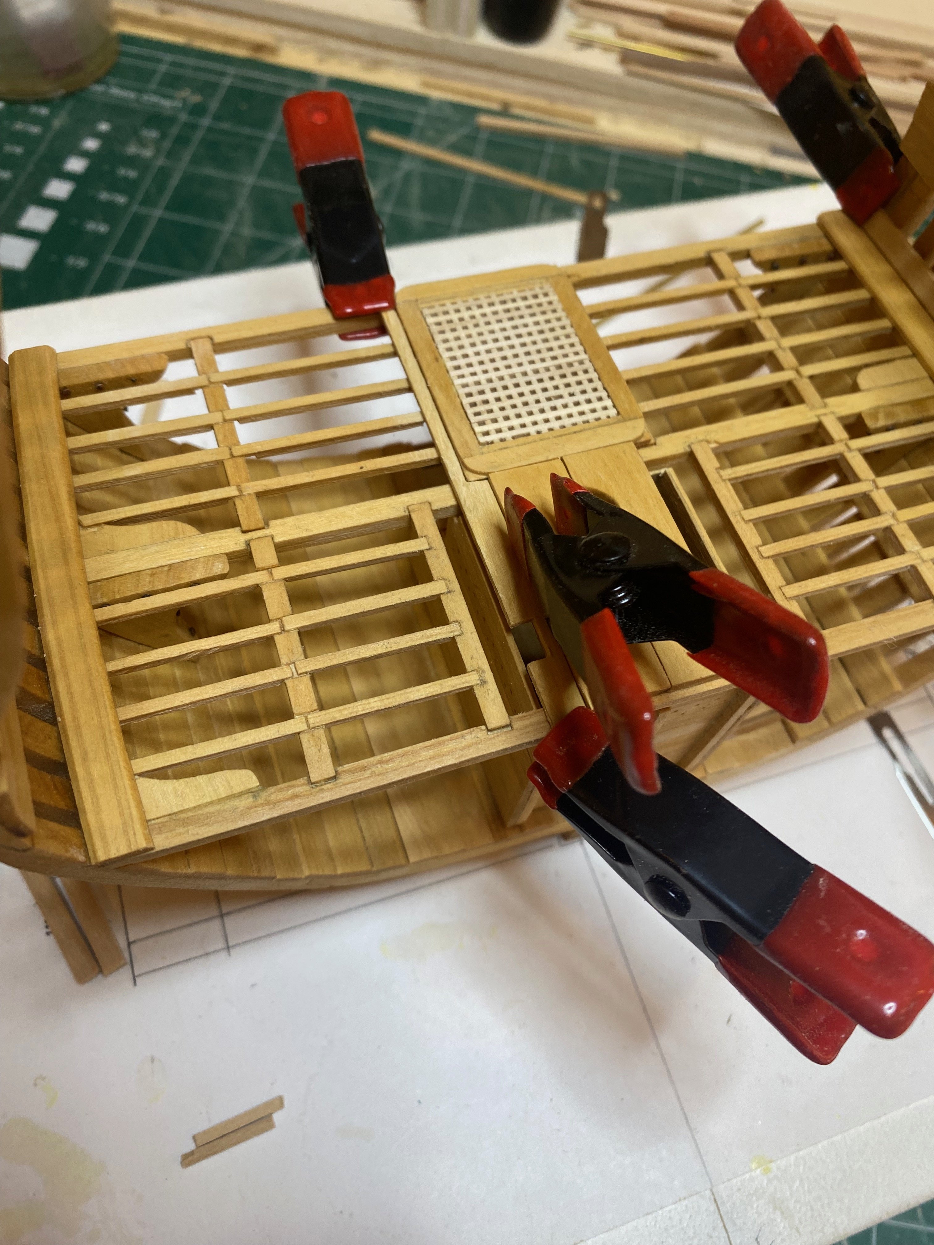
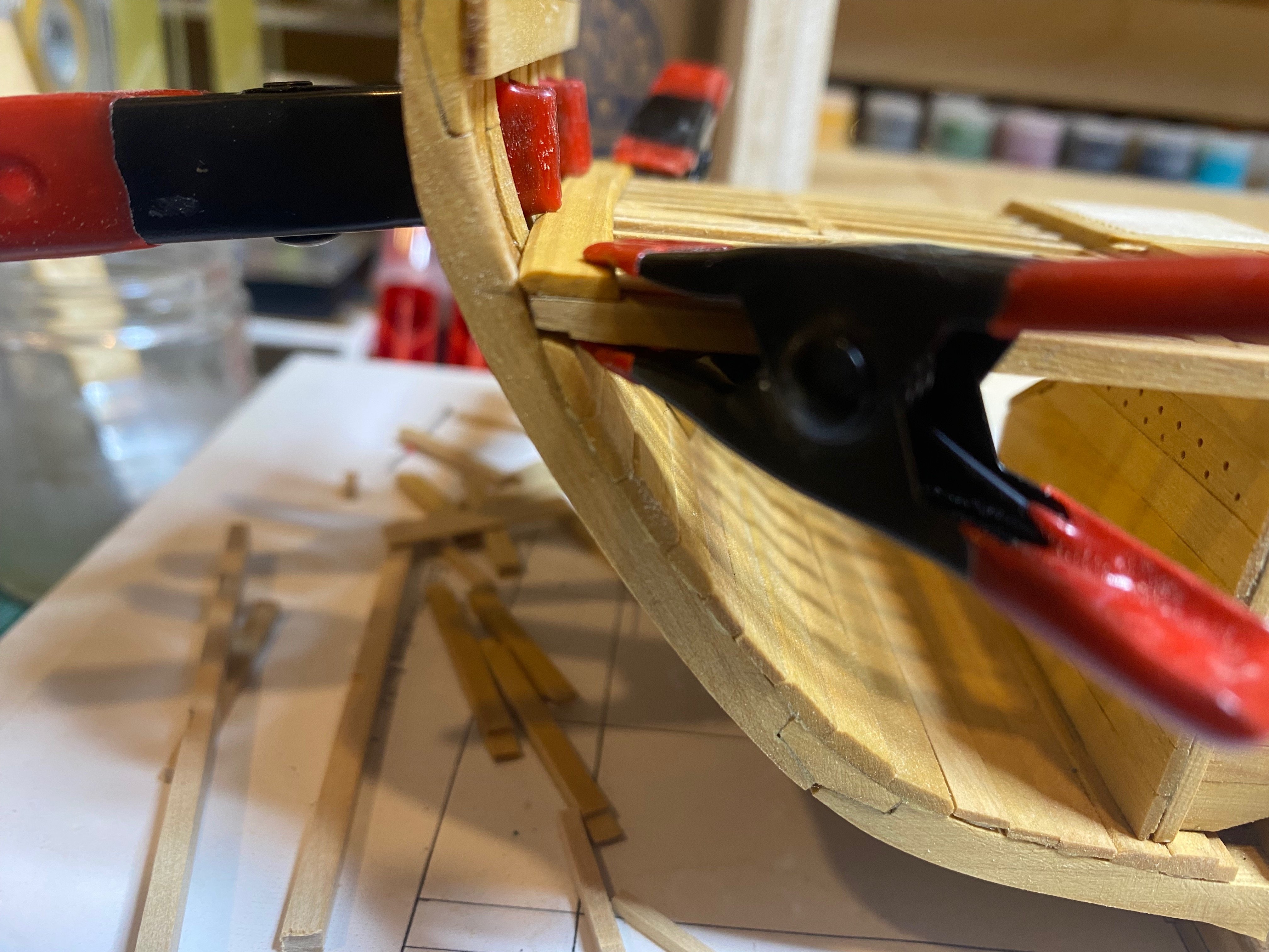
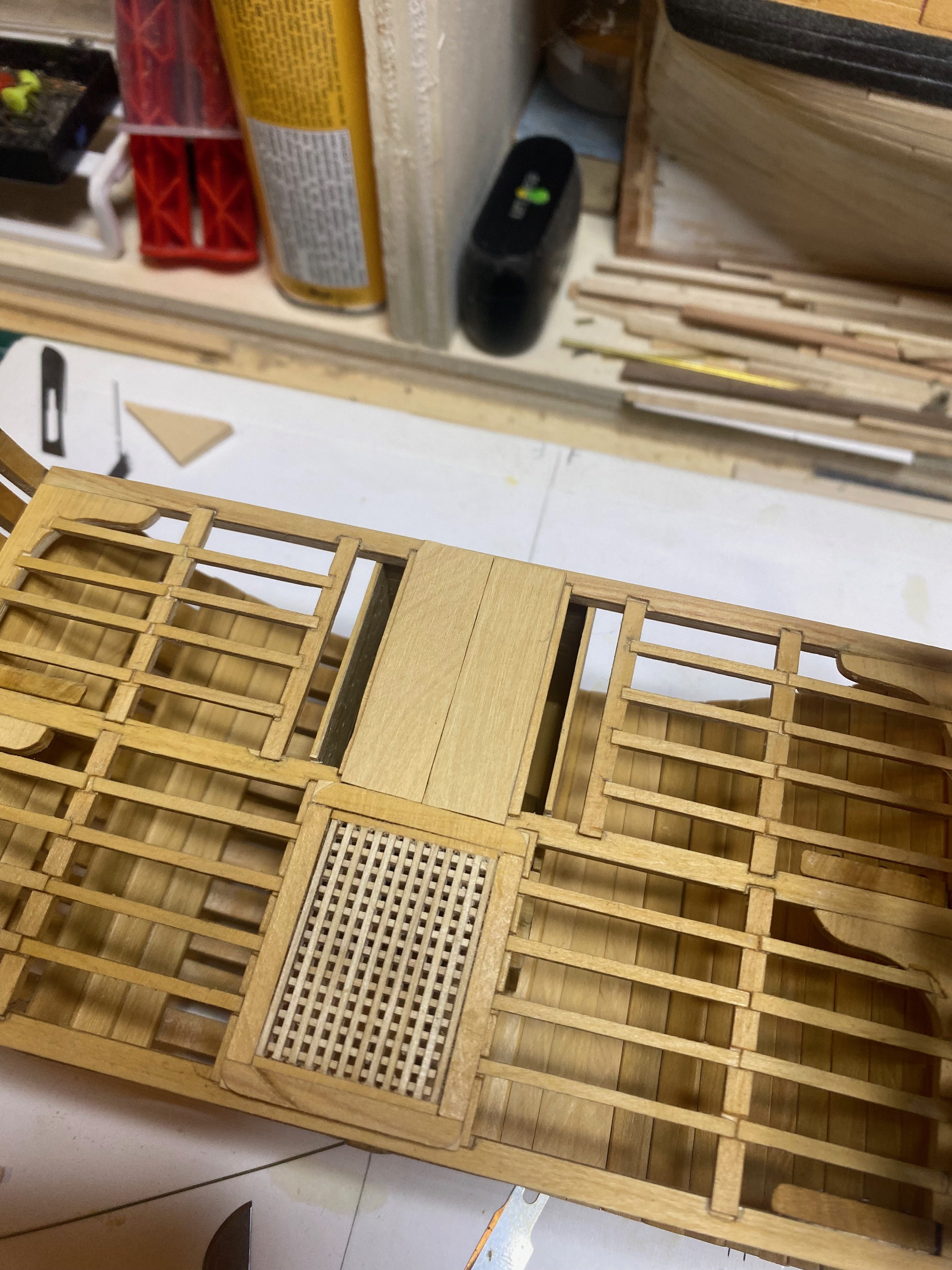
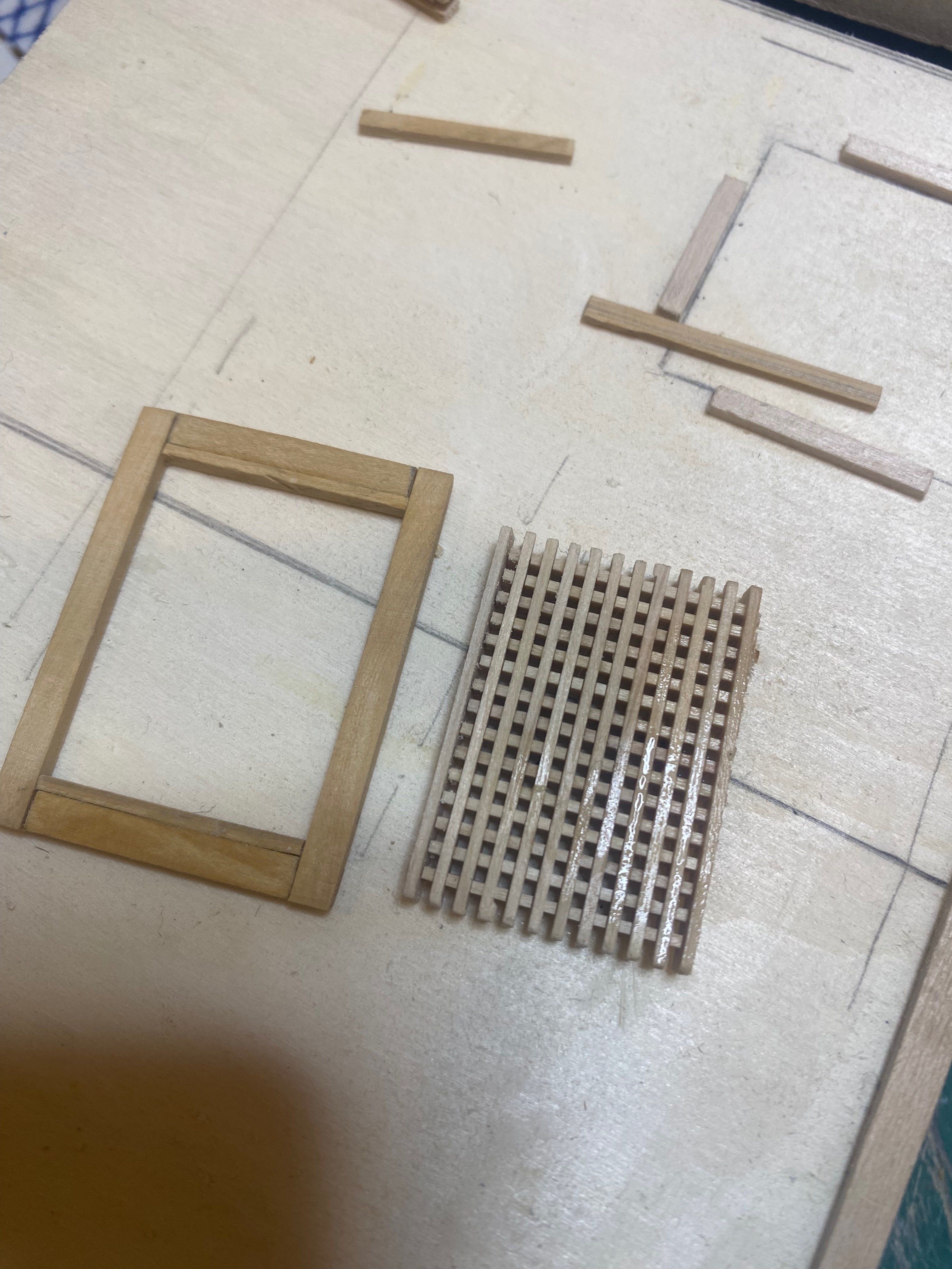
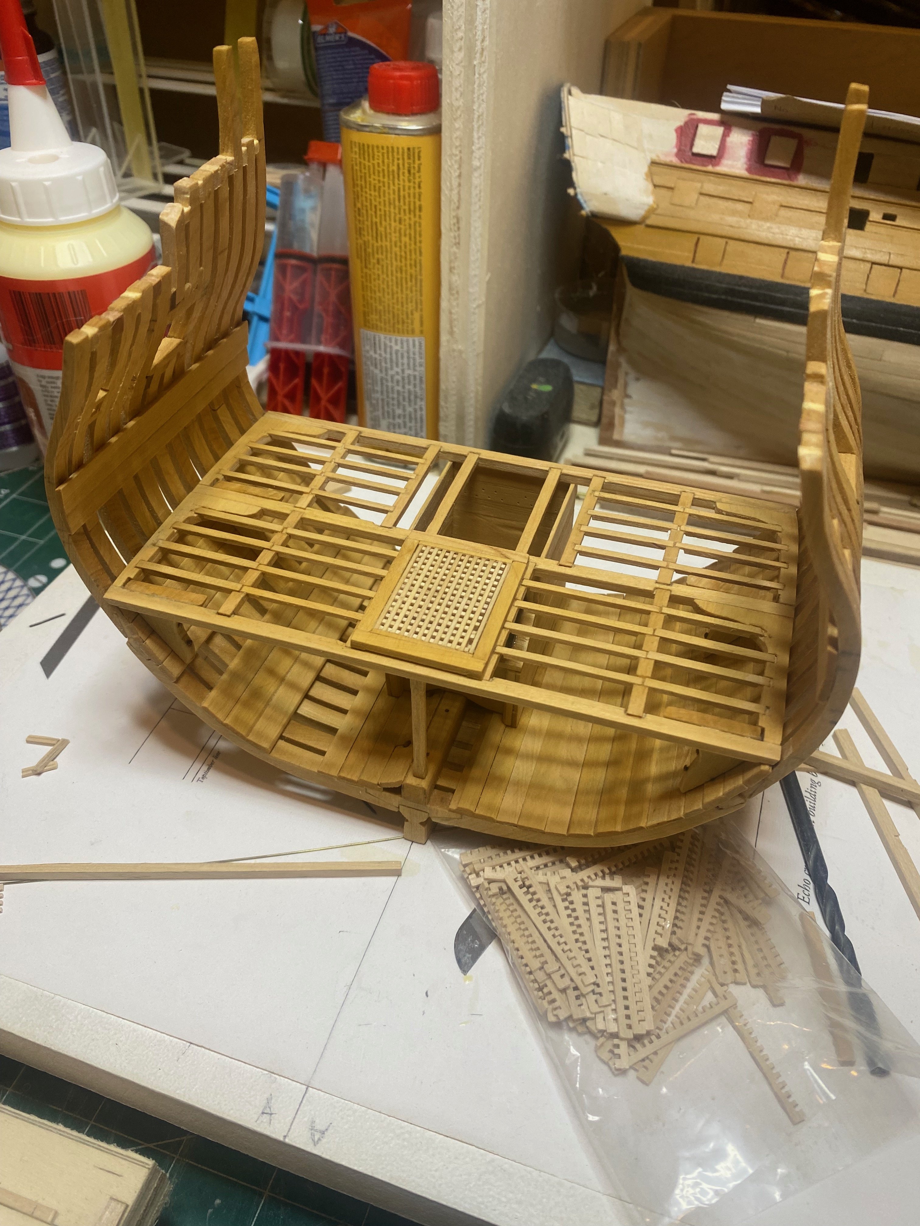
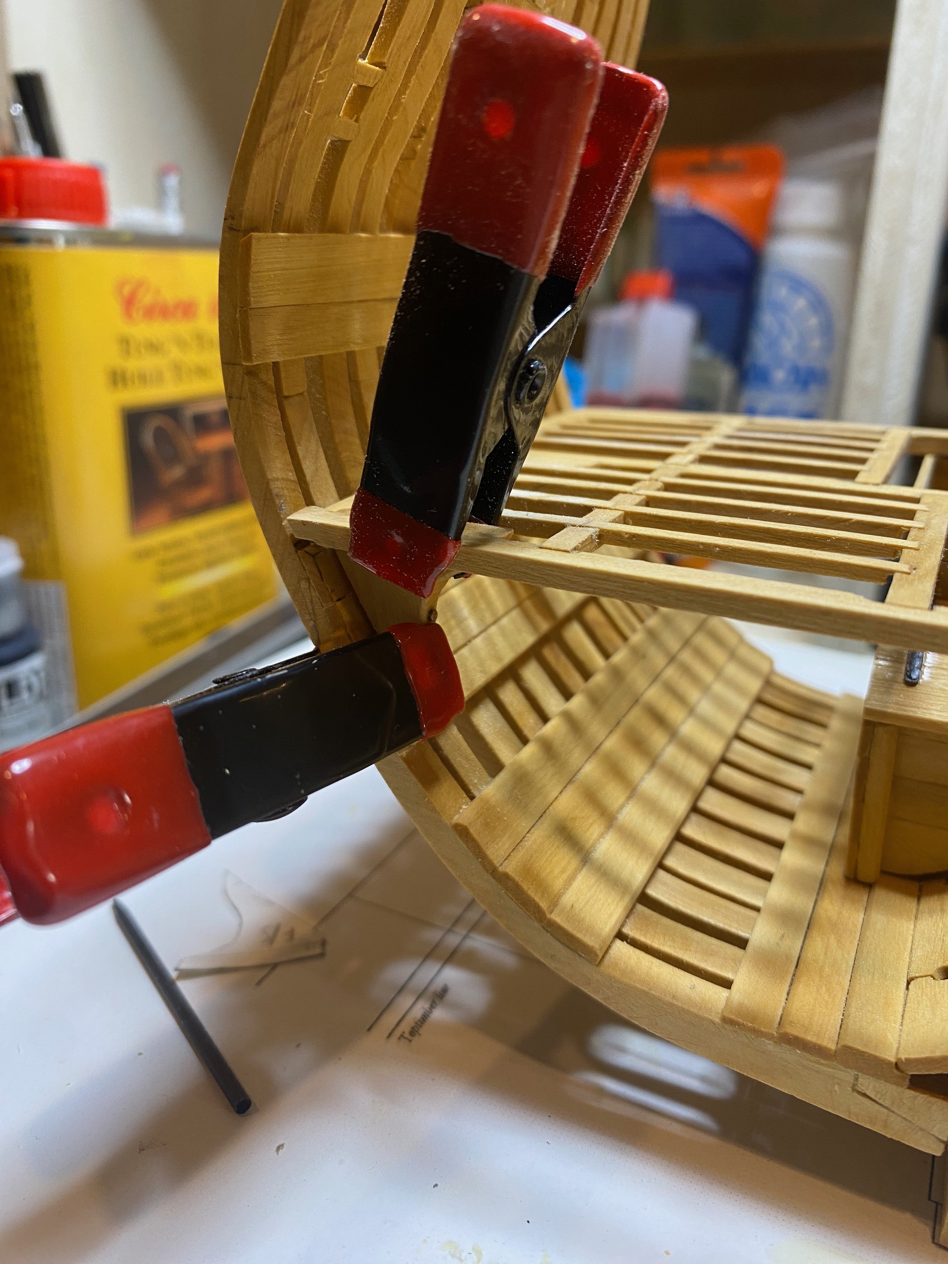
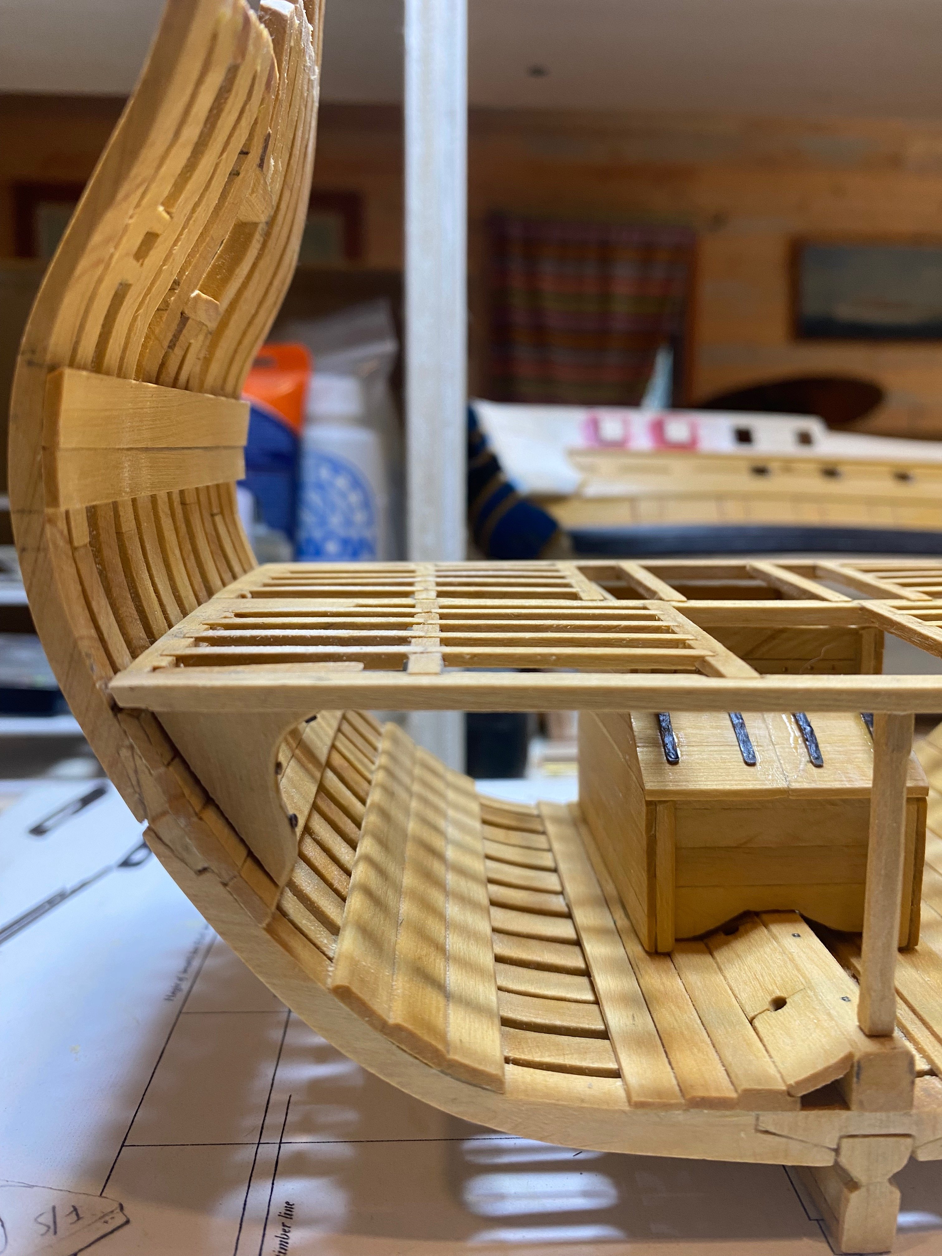
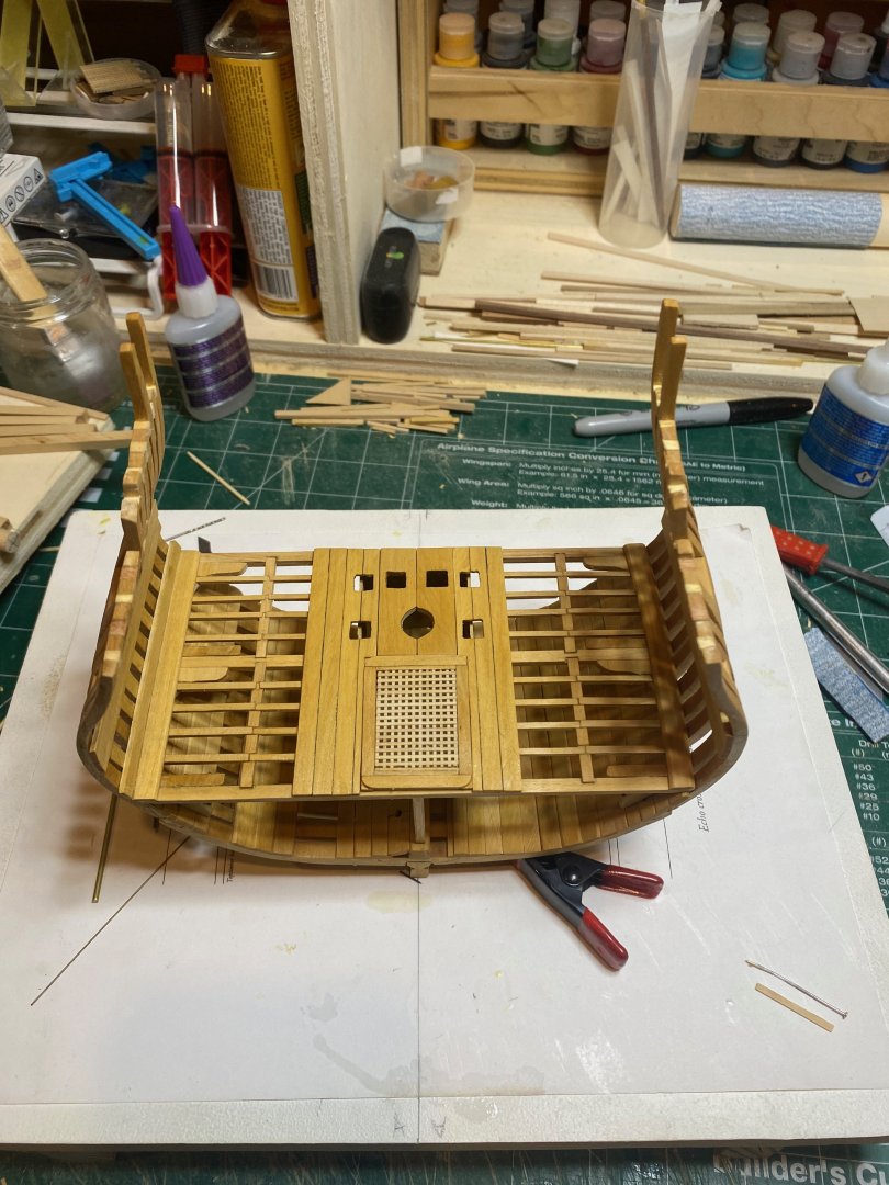
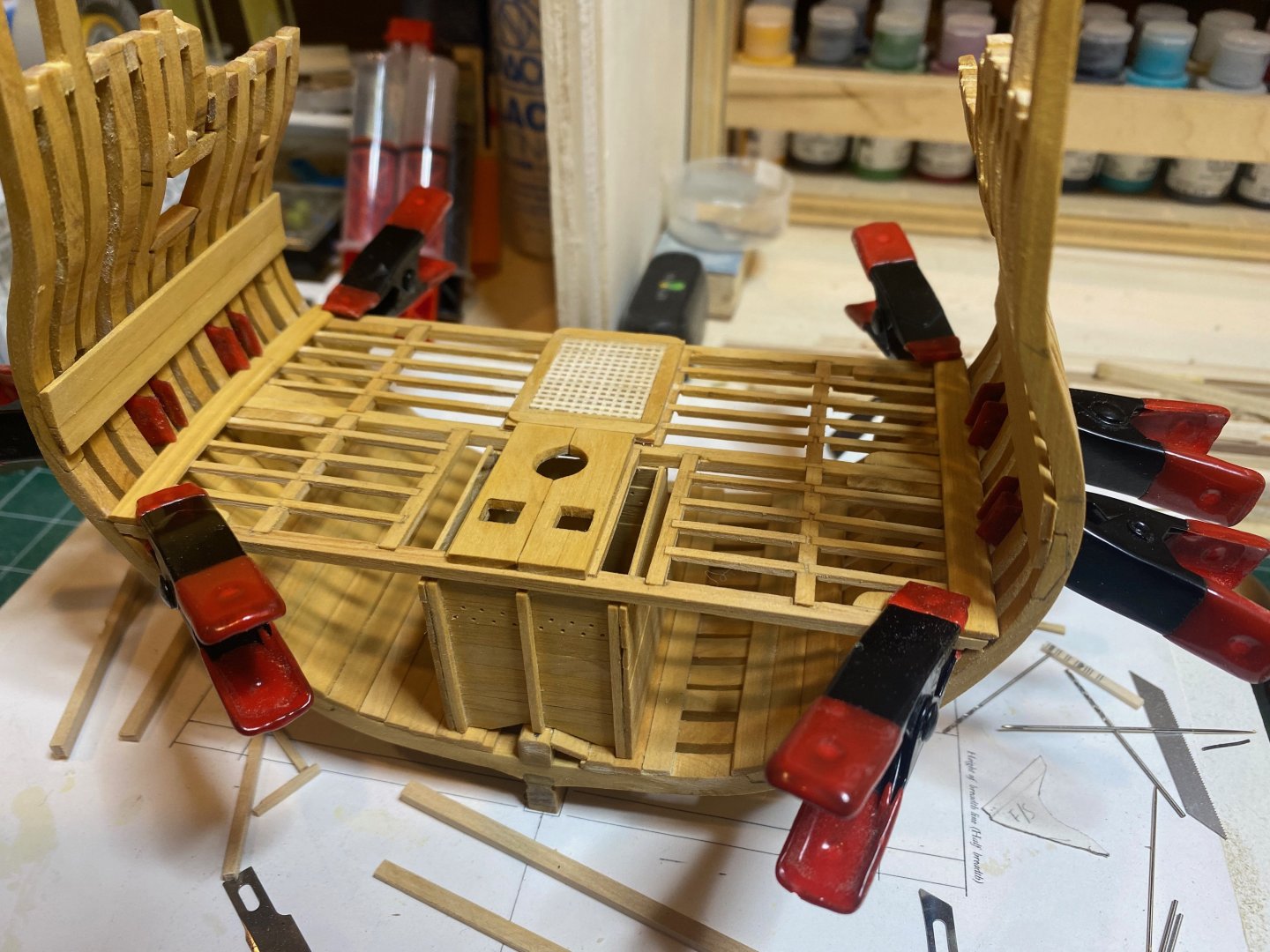
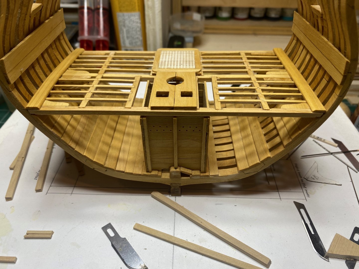
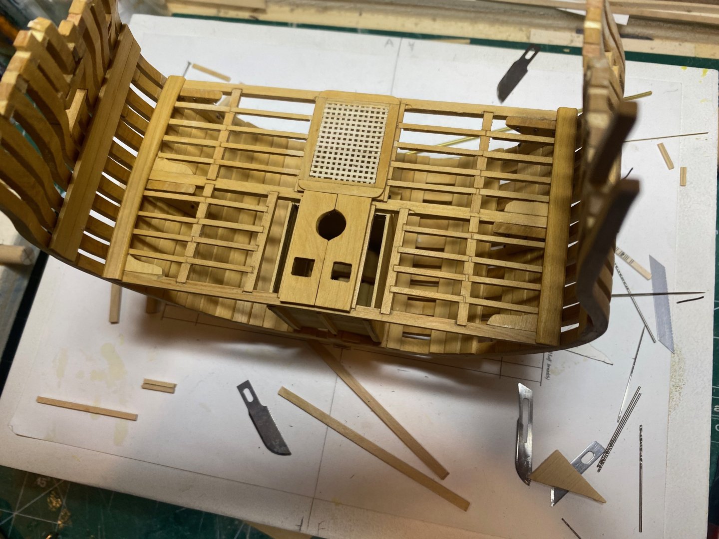
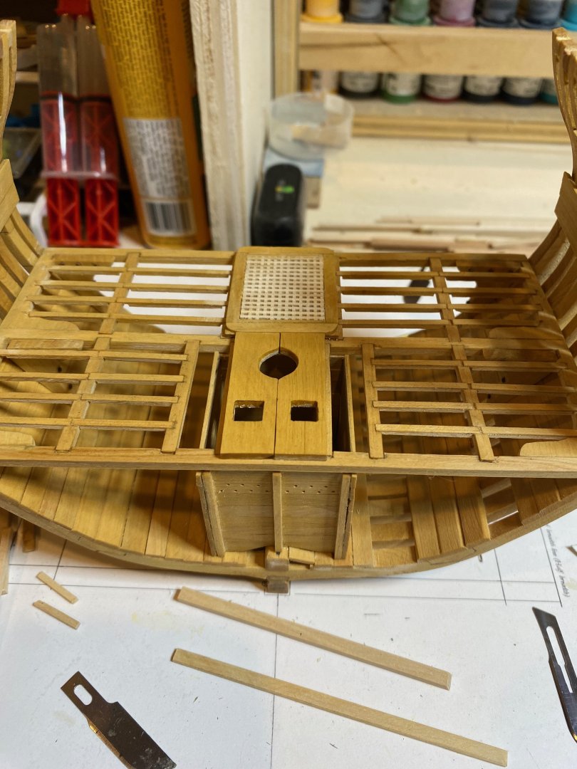
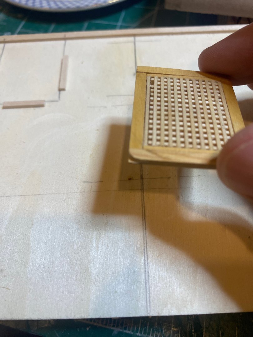
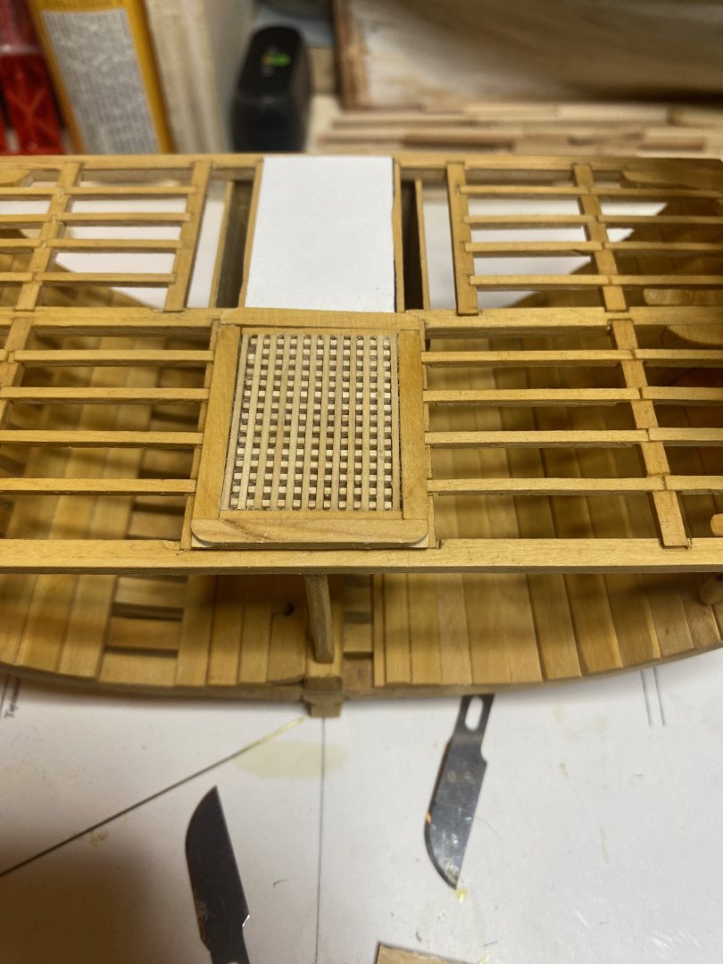
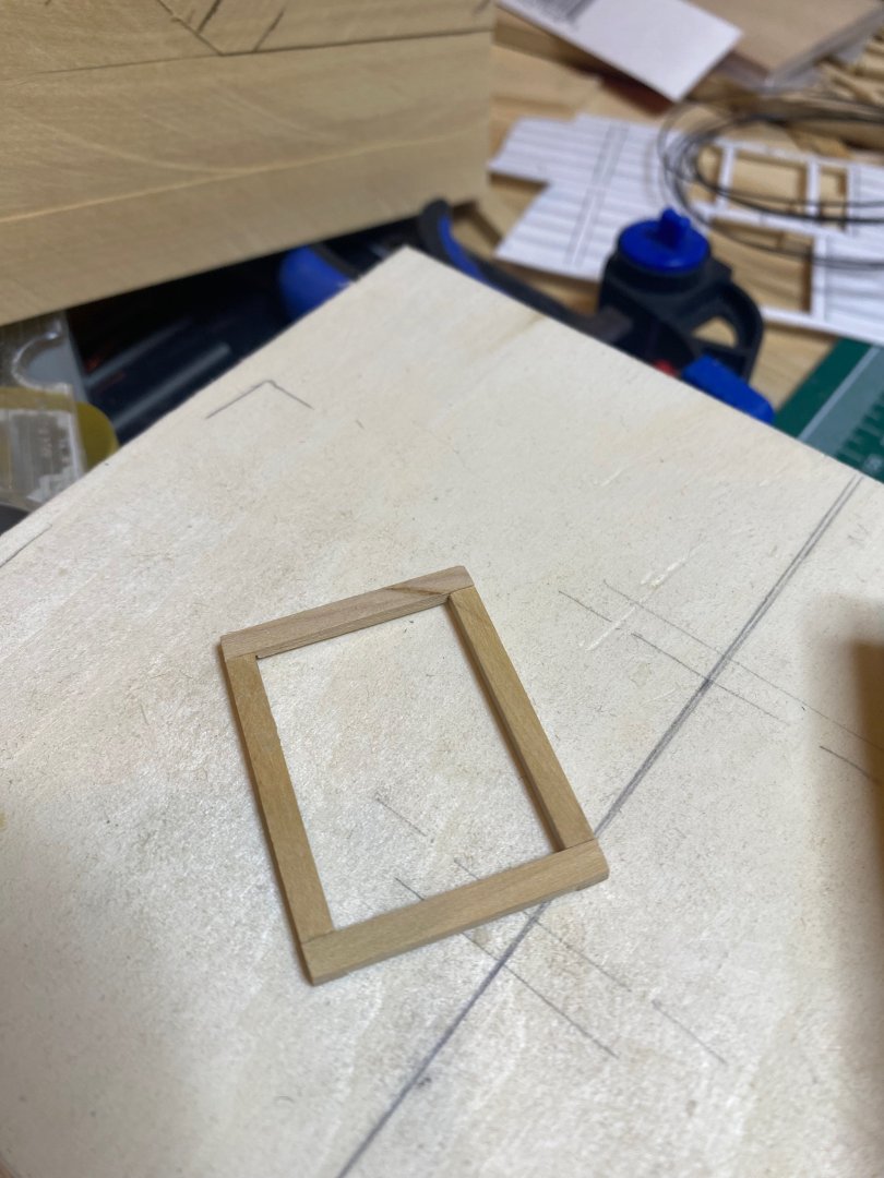
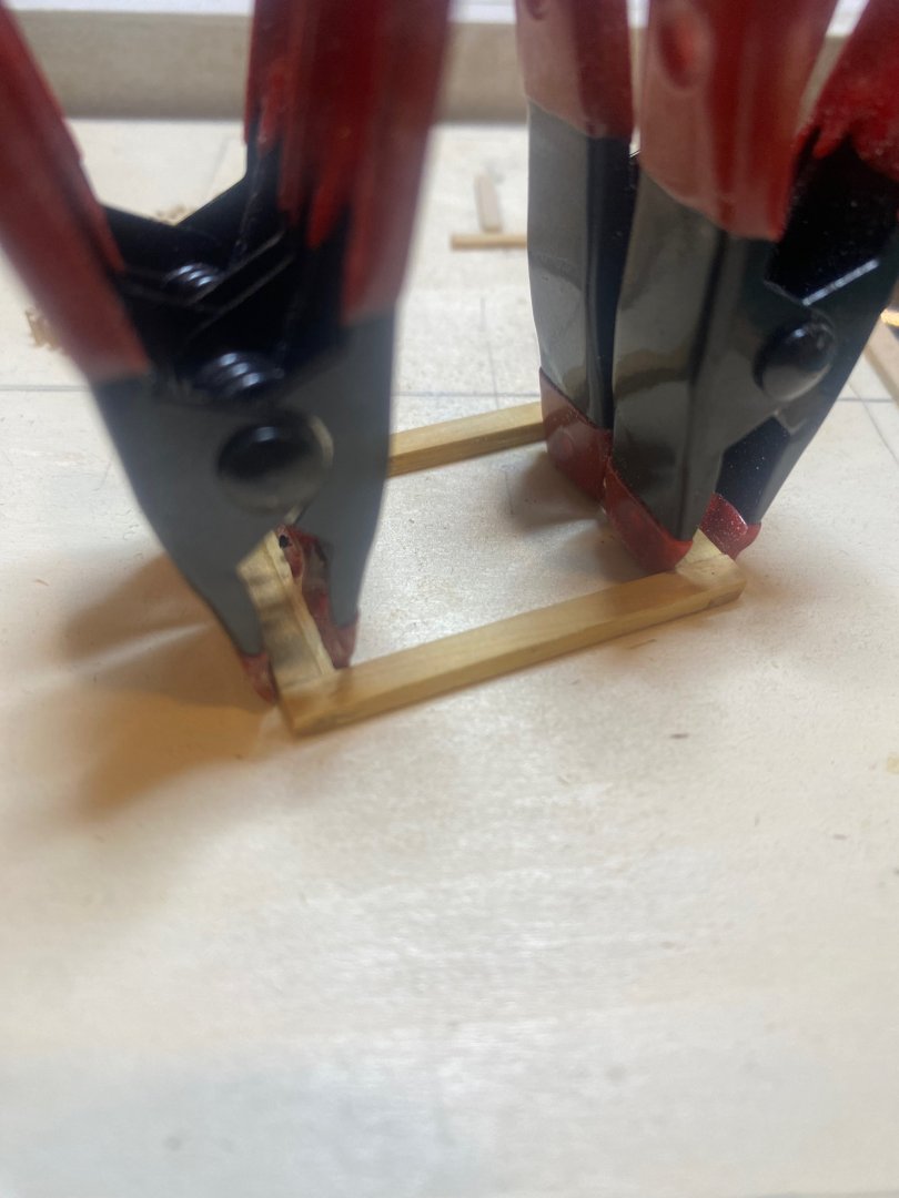
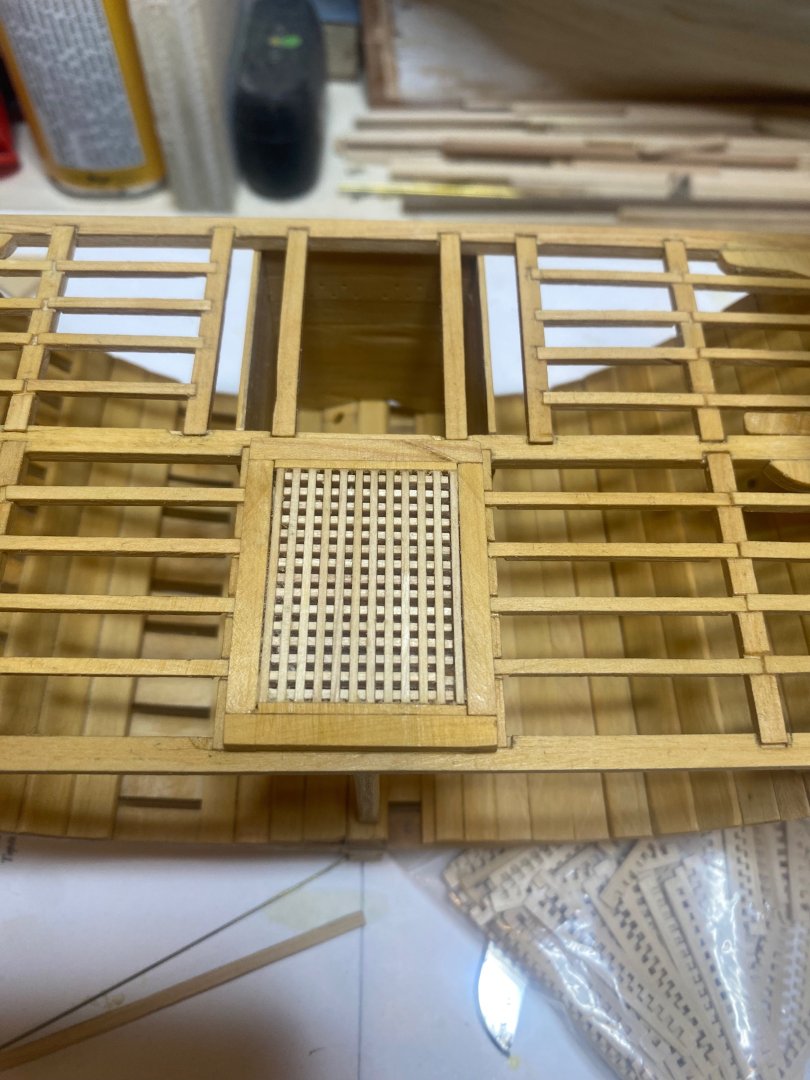
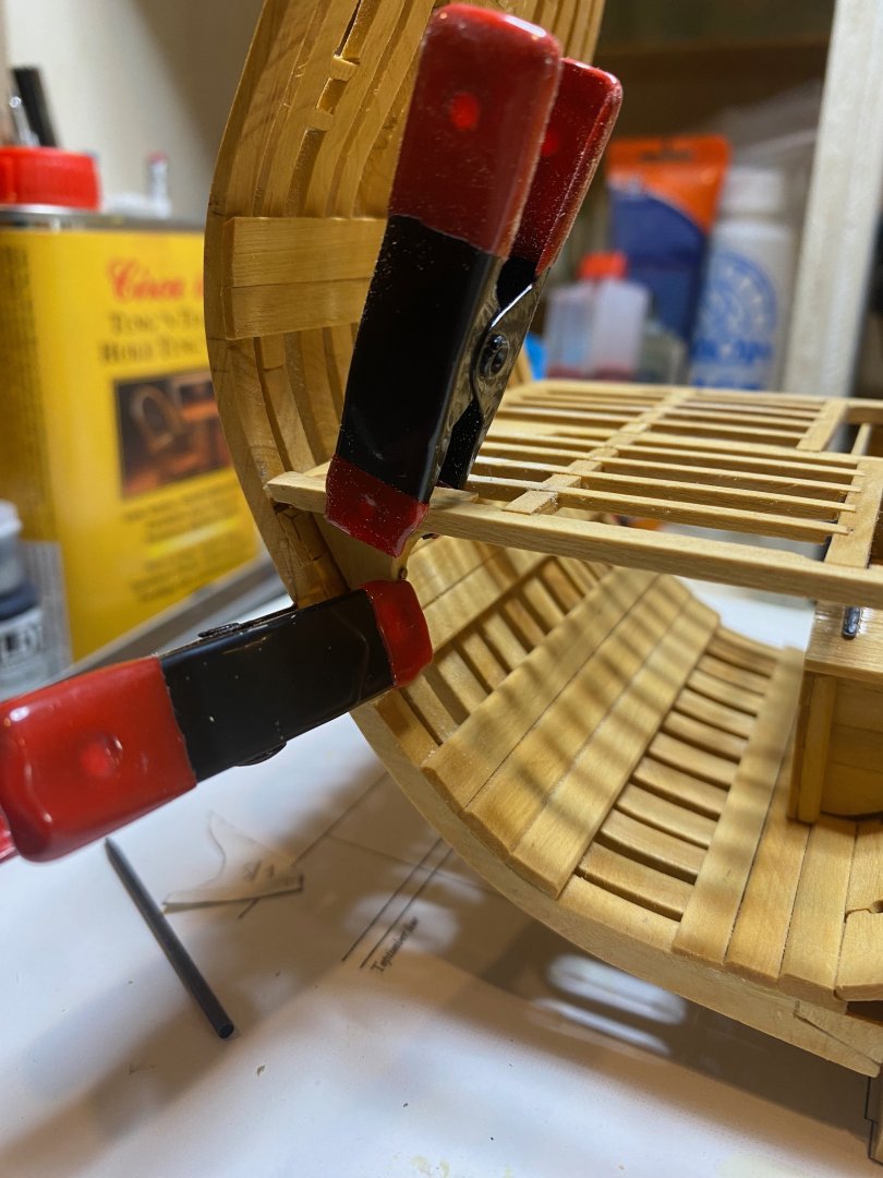
A bit more work at the bench this weekend - I decided to make the lower deck hatch. Here the practicum is a bit at odds with the model. The practicum speaks of a partial "aft hatch" behind this one, but this can't be, since the mast partners are immediately behind this hatch. There is also a lack of information in the practicum on the exact locations of the sheet and jeer bitts, so I'm a little confused as to where these should be - there is some info on this in the photos provided with the practicum, but it isn't really adequate to locating them....In any event, I did also go so far as to mill 11" and 10" square strips for the pump shafts (6) and the bitts (4) to use as blanks for working out the mast partners - though the upper deck framing will need at least to be partially complete before finalising these. The hatch came together pretty easily. I took a card template of its basic dimensions and laid this out on a sheet of scrap ply. I then arranged some battens around it to lock in the head ledges and coamings in the proper place. The head ledges and coamings fit together with lap joints which are pretty straightforward. The gratings were made from material scavenged from my never-to-be-finished Syren kit - these gratings are of roughly the correct size and were of sufficient quality (unlike those often supplied by other kit mnanufacturers) for these purposes. Because the gratings when assembled did not fit exactly right, I needed to add a couple of battens along the head ledges (image with clamps below) so that the gratings looked correct. Overall this went very smoothly. And it's nice to start creating more of the superstructural features of the model, which immediate (I think) make it more satisfying to the eye even in its unfinished state. Enjoy the photos and happy modelling hamilton


-
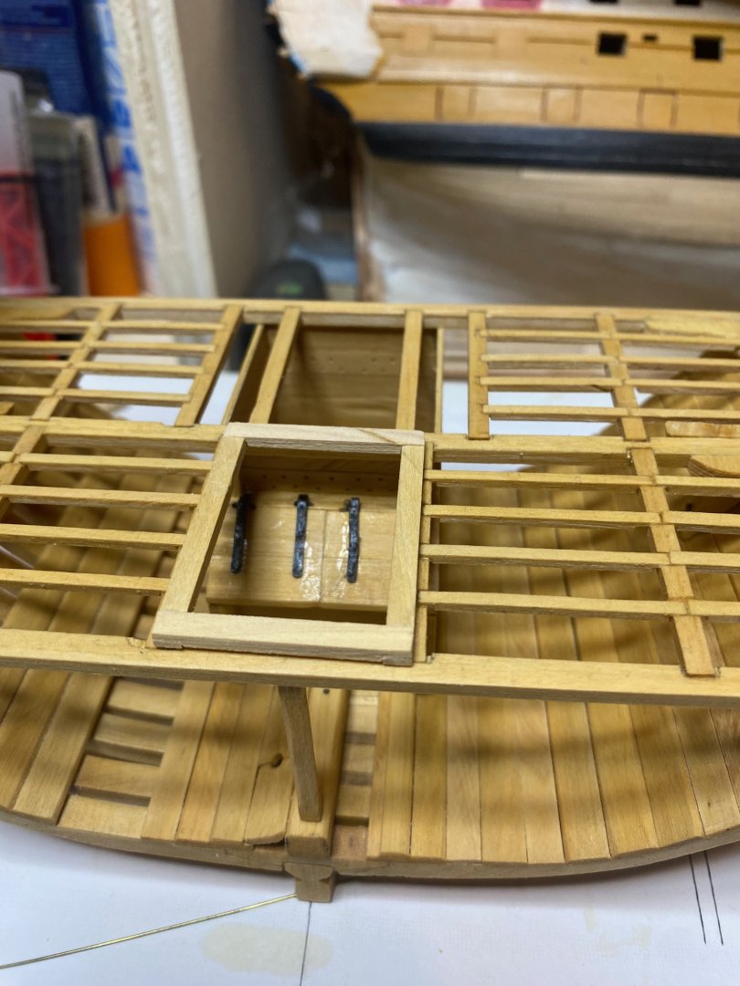
Yeah - my mum used to call me "knobbly knees" when I was a kid, and now I have not only 2 but maybe as many as 6 of them!! if it's not too tricky I might try prying the nails out and re-doing the bolts with just the shafts, but since they're now installed I worry about doing damage to other parts of the model.....so I may just write this off as a "learning experience" - it's nice, in my mid-50s, to still be having learning experiences!! hamilton
-
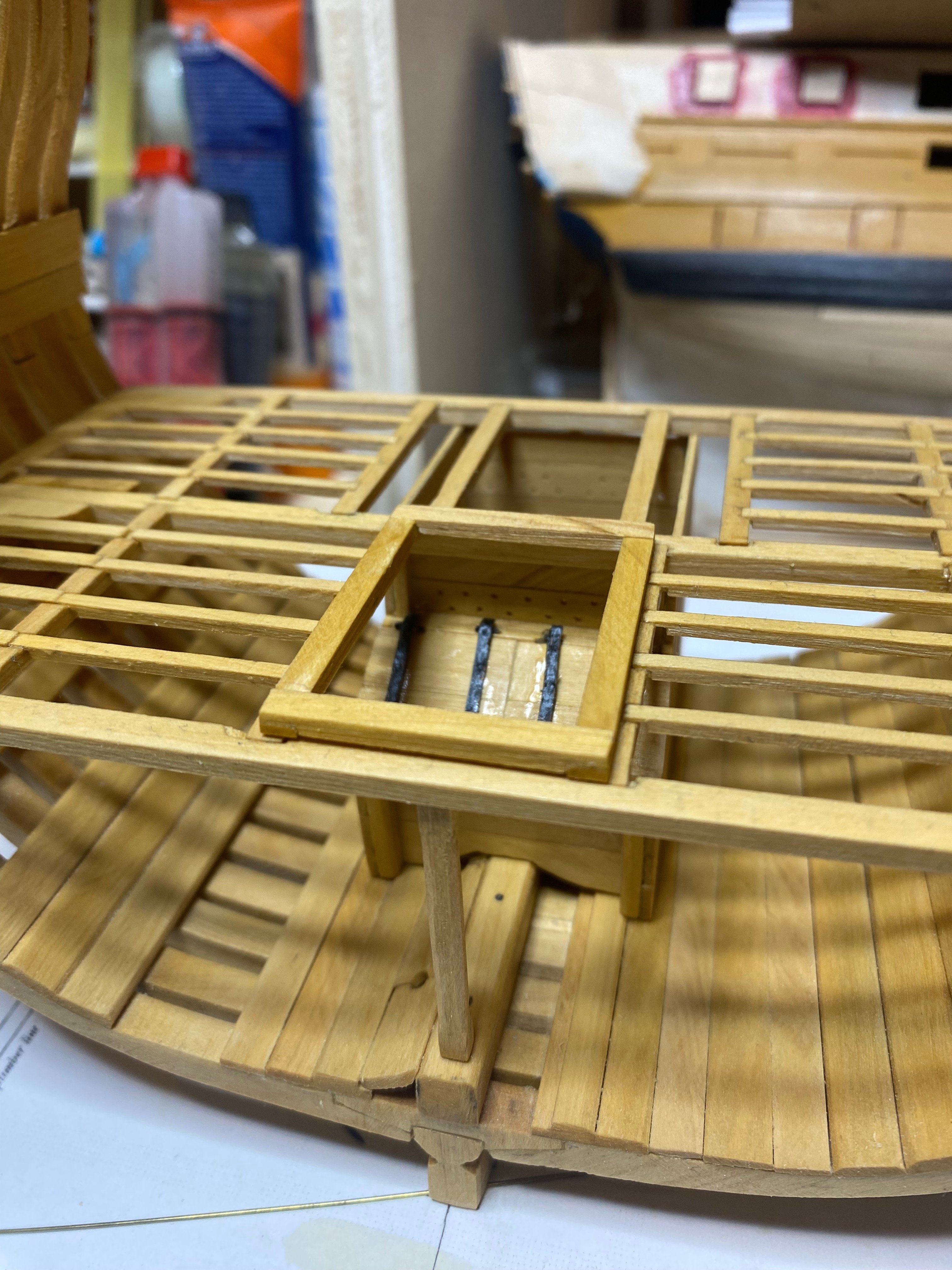
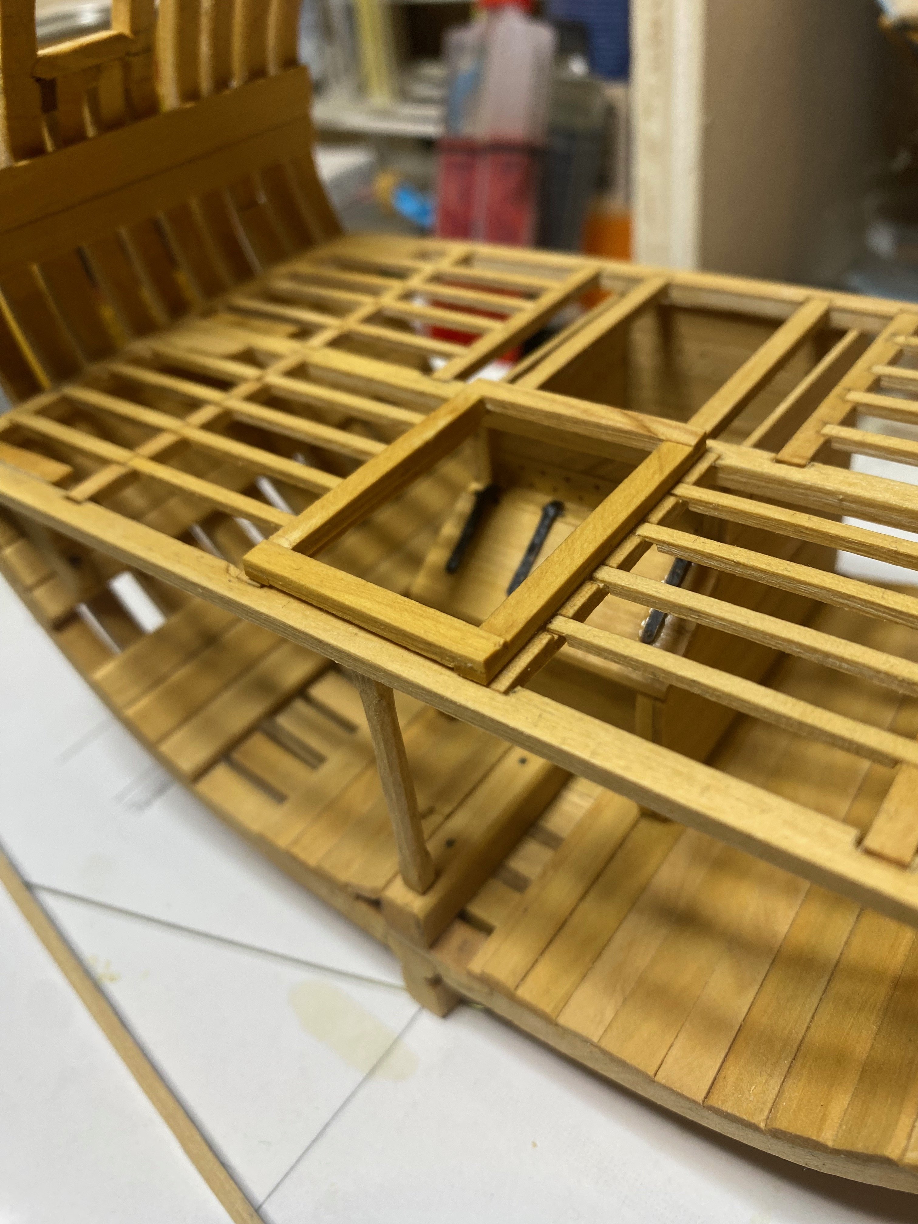
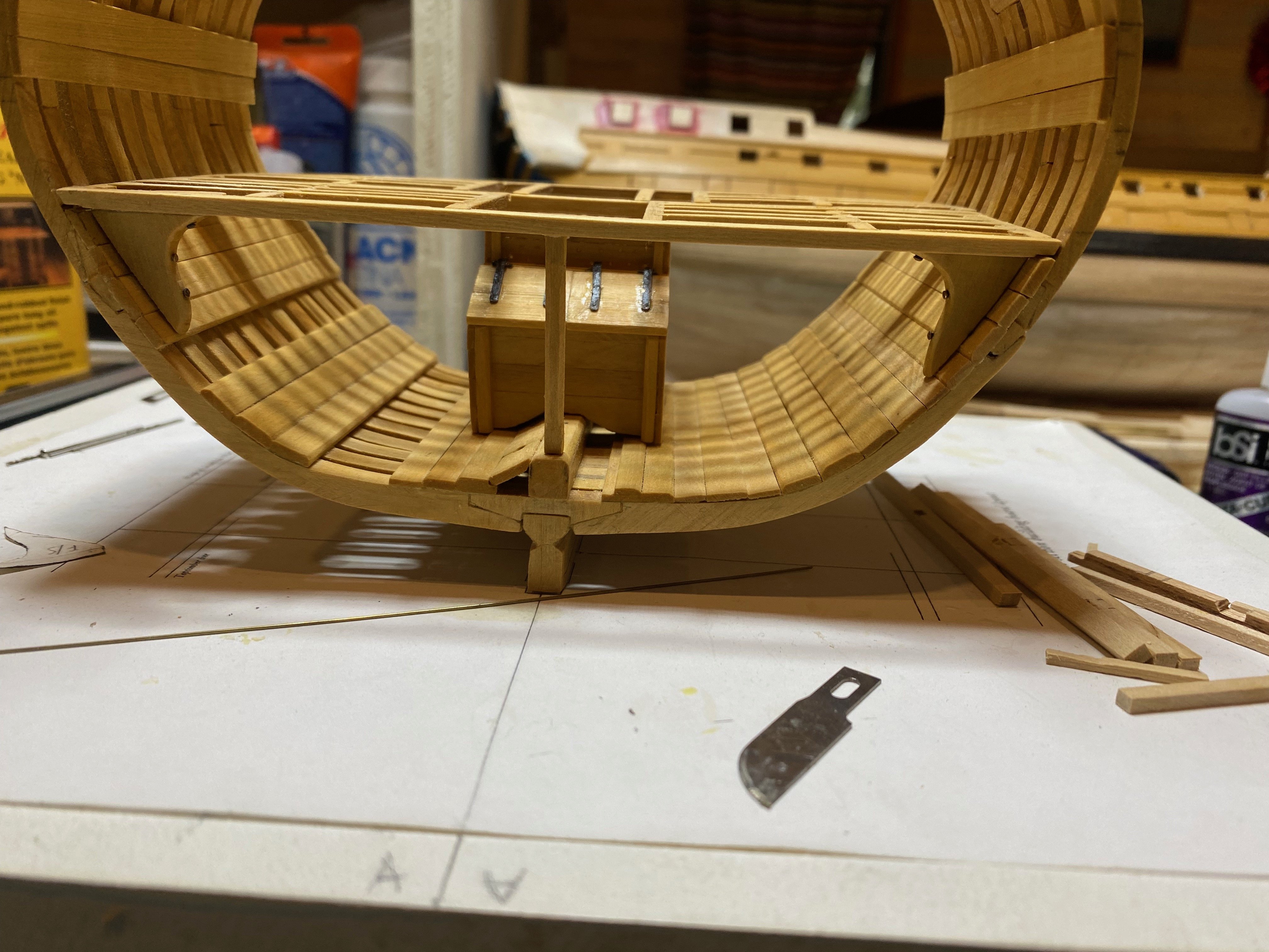
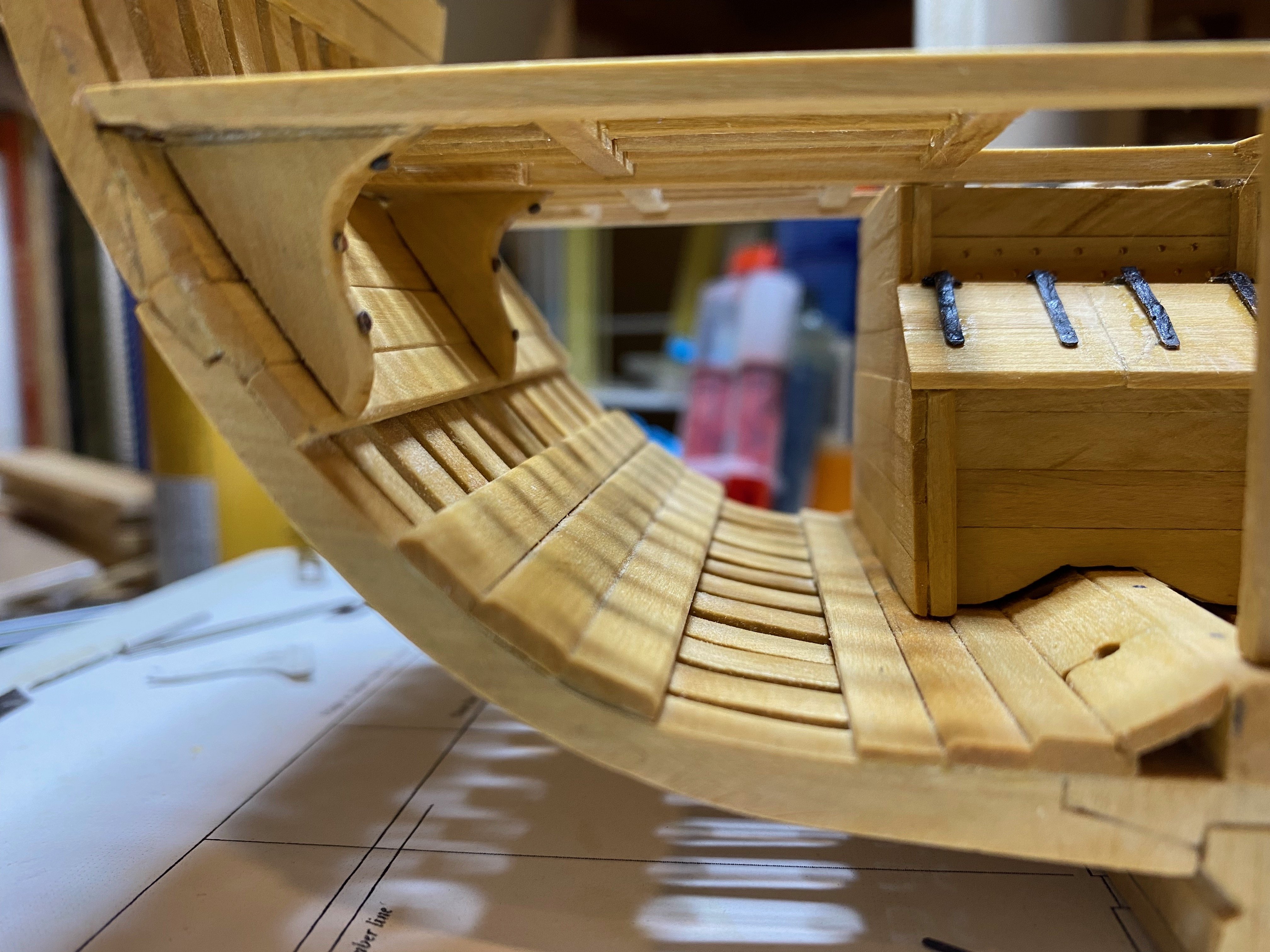
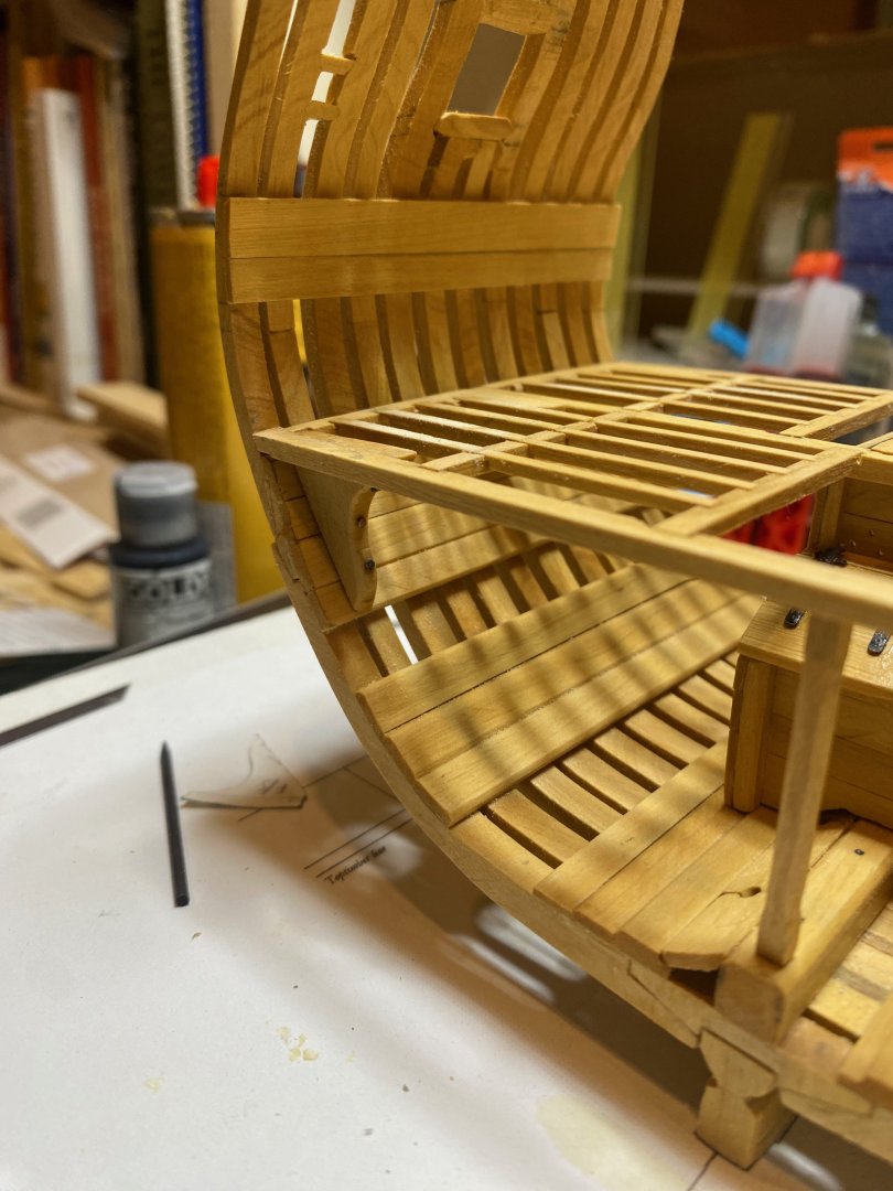
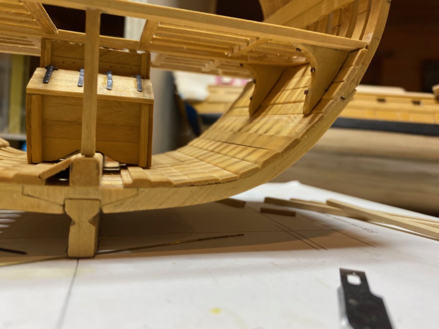
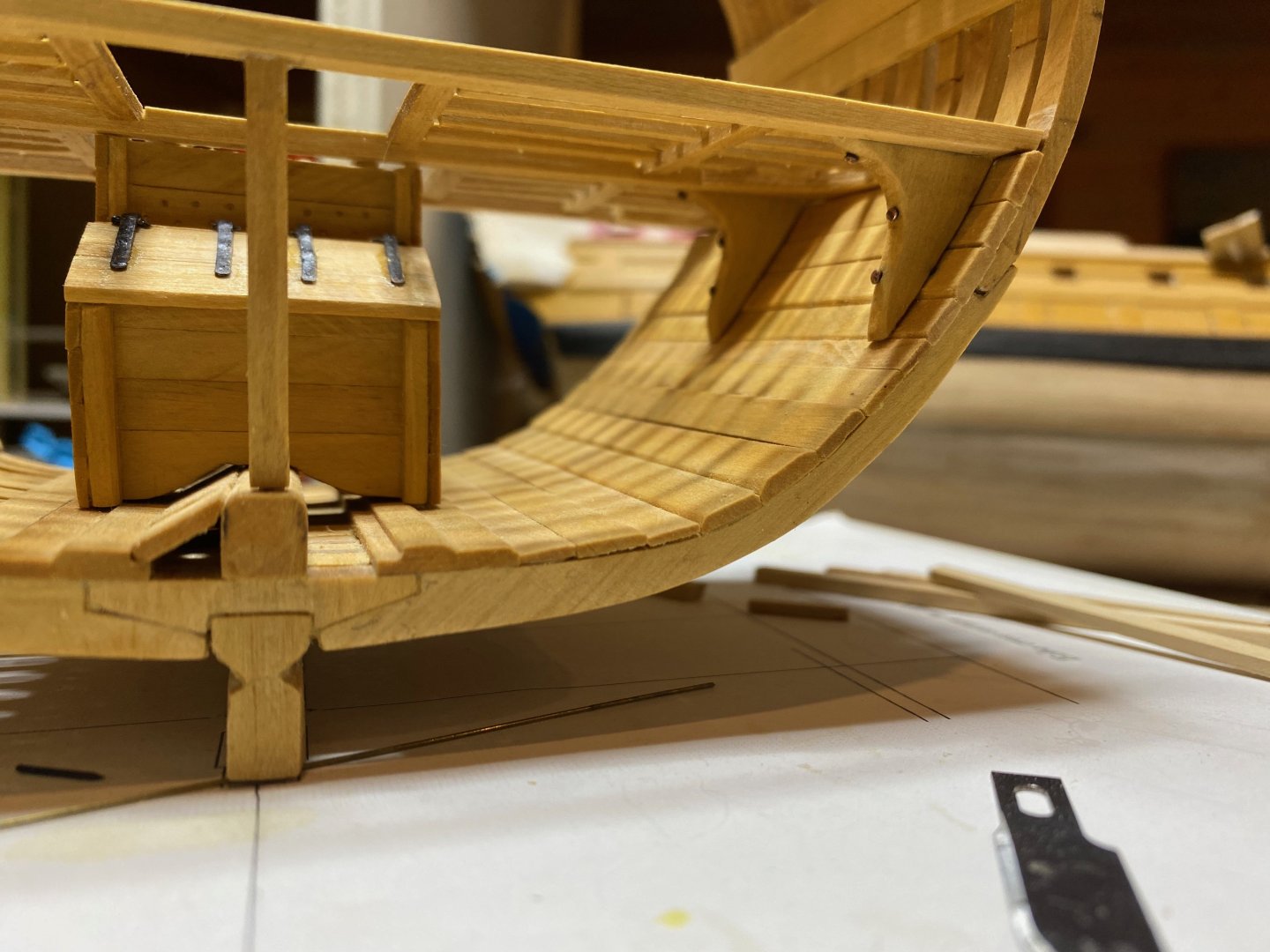
Whoa - I see my last actual update here was way back in October!! There has been precious little time for modelling, unfortunately, though I did spend a bit of time over the holidays doing some planning for the MS Flying Fish, which I don't plan on digging into for a while, but which drew my attention while taking a look through my inventory. Figured it never hurts to start planning and it was a nice break from inhaling sawdust and trying to wrap my head around the hanging knees. But I bit to bullet today and managed to complete these nettlesome parts.... I made a card pattern from the plans and tested it against each of the hanging knee positions (there are only 4 in total, so those of you building a full model in this style can please ignore or forgive my whining). It worked reasonable well for all of them so I traced it into some 6" boxwood sheet that I milled for this and other purposes. I decided it was best to go through the process of fabricating and fitting one of the knees before doing any of the others. I was not aiming for perfection, but for as nice a fit as I could achieve with my limited experience. In trying to fit and adjust the part I realised that it would be much easier to do if I committed to installing the well, pillar and lower deck framing assembly - so I did that first. It was then much easier to lightly clamp the part in place and test its fit and positioning. After applying a couple of coats of poly, I drill out for bolt heads on the inboard edge and aft faces where they bolt onto the deck beams - using brass nails for the bolts. In retrospect it would have been better to use only the shafts of these nails as the heads are pretty large at this scale.... In any event, once the first knee was in, the others went quite quickly. For next steps, I'm not entirely sure what I'll do next - I know I need to make blanks for the various pump shafts and bits, so I can mark out their positions on the lower deck framing prior to planking & completing the lower deck mast partners and hatch....but I also don't think it would hurt to do the waterways and in-board hull planking between decks....On the other hand, I feel like I should consider the upper deck framing, even if installing it is a ways off, since positioning of the pump shafts and bitts is necessary there too and it would make sense to mark positions on both decks to ensure decent passage of these parts....Regardless, it's also hard to say how much time I'll have in the near future - work is busy, lots going on with the family, and the Canadian economy is about to get pretty shaky, meaning we're tightening our belts up here. In any case, enjoy the photos and happy modelling! hamilton


-
Quick PS - just looked through my stock of St Roch photos and I wasn't able to identify anything on the lower hull that would look like a scupper for the sea chest - but I will head down to the MM to have a look around hamilton