


shipmodel
-
Posts
908 -
Joined
-
Last visited
Reputation Activity
-

 shipmodel got a reaction from popash42 in Queen Anne's Revenge 1710 by shipmodel - FINISHED - 1/36 scale
Log 33 – Fore Topsail
Hello again to all. Since the last entry I have made and hung the fore topsail. This is the first of the square sails that will be shown set and filling, and took somewhat longer to complete due to my inexperience. I had to go back a few times to understand all of the lines and to work out some technical problems.
Here is the yard, shaped as usual with cleats, stop cleats and blocks. At this point I still have to add the larger blocks near the center for the topgallant sheets. Also the stirrups and footropes.
1
The sail itself was laid out, like the lateen, on stiffened cloth. The panel lines and tabling lines were marked out, then the perimeter was painted with pH neutral white glue. When the glue was dry the sail was cut out and small triangle openings were cut along what would become the perimeter of the sail for the cringles. The sail was turned over and panel seams were lined on, offset about 3 scale inches to one side of the first set of seams.
2
The boltrope was set into the creased sail edge and trapped in place when the tabling was folded over and ironed closed. As with the lateen, the cringles were made by feeding a bend of the bolt rope through the previously cut openings to form the cringles. When the tabling was completely closed the various reinforcements were added to the back of the sail. These were made out of stiffened cloth that was marked with panel seams, if needed, then cut and glued to the main sail as shown on the plans. They were ironed down to the main sailcloth and should be very stable and secure. On the front of the sail two bands of reinforcement for the reef points were similarly cut, glued, and ironed.
3
Here you can see all of the elements of the sail, backlit and translucent.
4
A series of holes was drilled through the tabling along the top of the sail with about a 3/8” spacing. A continuous series of loops was sewn through the holes to lace the sail to the spar. Then it was set into a large plastic tub for stiffening.
5
The sail was painted with clear matte finish and weighted with about half a cup of rice in a plastic bag. It was left to dry overnight and, once removed from the jig, had a pleasing catenary curve to the three free sides.
6
Holes were drilled through the reef bands and the reef points were knotted, glued into the holes, and trimmed. Matte finish was painted on to hold them down on both sides of the sail. Clew blocks were tied to the lower corners and the sheets were knotted and laced through the clew cringles. The sail was hung on the mast and the parrell was strapped around the mast and yard. In the photo you can see the running ends of the topsail lifts (the heavier light colored lines) are hanging down and have not been belayed. There are clips on their lower ends to provide some weight and tension on the system to keep things from getting tangled. The clips also remind me which lines have not been belayed yet.
7
The tie with its fiddle block already seized in was fed from aft to forward through a sheave hole in the mast under the trestletrees. It was taken down around the yard and attached with a rolling hitch. The fiddle block at the running end of the tye is the top of a three part purchase hooked into an eyebolt in the top. The halyard belays to a cleat on the mast near the deck.
8
The lifts were laced through the fiddle blocks at the yardarm and led down towards the deck through the lubber holes, but not yet secured until the sheets were led through the sheet blocks on the main yard then down through the sheaves in the bitts forward of the mast. Then both sets of lines could be tensioned against each other. The braces were run from the main topmast stay, through several sets of blocks to a timberhead on the edge of the foredeck. They can be seen in some later photos. That completed the spar handling lines. The sail handling lines were then run, which completed the rigging to the topsail.
Here is the sail fully rigged as seen from forward.
9
In this view the lighting was varied so the sail handling lines can be seen a bit clearer. The fore topsail, like the other square sails, has p/s pairs of clewlines, leachlines, buntlines, and bowlines. Eight more lines for each sail. I had never previously fully rigged a ship, and the level of complexity with all these lines is a real eye-opener.
The bowlines start as a triple bridle from the cringles on either side of the sail. They lead to blocks on pendants at the end of the bowsprit, then aft through the gammon blocks and up to cleats on the foredeck. The buntines lead from cringles at the foot of the sail, through lead blocks on the yard, through blocks strapped to the topmast stay, and then to the deck. Similarly, the leach lines run from the upper side cringles through lead blocks and down to the deck.
10
In this closeup of the masthead you can see those lead blocks on the yard and stay.
11
From aft in these two views you can see the braces and clewlines.
12
13
Each of the sail handling lines goes down to a tackle hooked to the eyebolts around the base of the mast. It is starting to get very crowded here. The halyard is belayed to the mast cleat with several turns of line and a yacht hitch, but no glue. All of the belaying points will be painted with matte finish only after they are all done.
14
I try to leave extra line on the belaying point and delay the final securing till very late so that when, not if, I make a mistake I can correct it more easily. For example, here is the first photo of the halyard tackle on the mast top. Looking at it I could see that the halyard was running through one of the side lubber holes and made a fairly acute angle as it went through the lubber hole to the deck. Such a kink is a mistake.
15
In most cases this would be difficult to correct. Instead, I just had to untie the halyard from the cleat and re-run it properly, belaying it to the cleat again. Although it took some finicky work with two tweezers, it only took 15 minutes, not an hour. A very small point, but one that would have nagged at me at 2 am.
16
So here is the current overall look.
17
Main topmast next.
Be well
Dan
-
 shipmodel got a reaction from GuntherMT in Queen Anne's Revenge 1710 by shipmodel - FINISHED - 1/36 scale
Log 33 – Fore Topsail
Hello again to all. Since the last entry I have made and hung the fore topsail. This is the first of the square sails that will be shown set and filling, and took somewhat longer to complete due to my inexperience. I had to go back a few times to understand all of the lines and to work out some technical problems.
Here is the yard, shaped as usual with cleats, stop cleats and blocks. At this point I still have to add the larger blocks near the center for the topgallant sheets. Also the stirrups and footropes.
1
The sail itself was laid out, like the lateen, on stiffened cloth. The panel lines and tabling lines were marked out, then the perimeter was painted with pH neutral white glue. When the glue was dry the sail was cut out and small triangle openings were cut along what would become the perimeter of the sail for the cringles. The sail was turned over and panel seams were lined on, offset about 3 scale inches to one side of the first set of seams.
2
The boltrope was set into the creased sail edge and trapped in place when the tabling was folded over and ironed closed. As with the lateen, the cringles were made by feeding a bend of the bolt rope through the previously cut openings to form the cringles. When the tabling was completely closed the various reinforcements were added to the back of the sail. These were made out of stiffened cloth that was marked with panel seams, if needed, then cut and glued to the main sail as shown on the plans. They were ironed down to the main sailcloth and should be very stable and secure. On the front of the sail two bands of reinforcement for the reef points were similarly cut, glued, and ironed.
3
Here you can see all of the elements of the sail, backlit and translucent.
4
A series of holes was drilled through the tabling along the top of the sail with about a 3/8” spacing. A continuous series of loops was sewn through the holes to lace the sail to the spar. Then it was set into a large plastic tub for stiffening.
5
The sail was painted with clear matte finish and weighted with about half a cup of rice in a plastic bag. It was left to dry overnight and, once removed from the jig, had a pleasing catenary curve to the three free sides.
6
Holes were drilled through the reef bands and the reef points were knotted, glued into the holes, and trimmed. Matte finish was painted on to hold them down on both sides of the sail. Clew blocks were tied to the lower corners and the sheets were knotted and laced through the clew cringles. The sail was hung on the mast and the parrell was strapped around the mast and yard. In the photo you can see the running ends of the topsail lifts (the heavier light colored lines) are hanging down and have not been belayed. There are clips on their lower ends to provide some weight and tension on the system to keep things from getting tangled. The clips also remind me which lines have not been belayed yet.
7
The tie with its fiddle block already seized in was fed from aft to forward through a sheave hole in the mast under the trestletrees. It was taken down around the yard and attached with a rolling hitch. The fiddle block at the running end of the tye is the top of a three part purchase hooked into an eyebolt in the top. The halyard belays to a cleat on the mast near the deck.
8
The lifts were laced through the fiddle blocks at the yardarm and led down towards the deck through the lubber holes, but not yet secured until the sheets were led through the sheet blocks on the main yard then down through the sheaves in the bitts forward of the mast. Then both sets of lines could be tensioned against each other. The braces were run from the main topmast stay, through several sets of blocks to a timberhead on the edge of the foredeck. They can be seen in some later photos. That completed the spar handling lines. The sail handling lines were then run, which completed the rigging to the topsail.
Here is the sail fully rigged as seen from forward.
9
In this view the lighting was varied so the sail handling lines can be seen a bit clearer. The fore topsail, like the other square sails, has p/s pairs of clewlines, leachlines, buntlines, and bowlines. Eight more lines for each sail. I had never previously fully rigged a ship, and the level of complexity with all these lines is a real eye-opener.
The bowlines start as a triple bridle from the cringles on either side of the sail. They lead to blocks on pendants at the end of the bowsprit, then aft through the gammon blocks and up to cleats on the foredeck. The buntines lead from cringles at the foot of the sail, through lead blocks on the yard, through blocks strapped to the topmast stay, and then to the deck. Similarly, the leach lines run from the upper side cringles through lead blocks and down to the deck.
10
In this closeup of the masthead you can see those lead blocks on the yard and stay.
11
From aft in these two views you can see the braces and clewlines.
12
13
Each of the sail handling lines goes down to a tackle hooked to the eyebolts around the base of the mast. It is starting to get very crowded here. The halyard is belayed to the mast cleat with several turns of line and a yacht hitch, but no glue. All of the belaying points will be painted with matte finish only after they are all done.
14
I try to leave extra line on the belaying point and delay the final securing till very late so that when, not if, I make a mistake I can correct it more easily. For example, here is the first photo of the halyard tackle on the mast top. Looking at it I could see that the halyard was running through one of the side lubber holes and made a fairly acute angle as it went through the lubber hole to the deck. Such a kink is a mistake.
15
In most cases this would be difficult to correct. Instead, I just had to untie the halyard from the cleat and re-run it properly, belaying it to the cleat again. Although it took some finicky work with two tweezers, it only took 15 minutes, not an hour. A very small point, but one that would have nagged at me at 2 am.
16
So here is the current overall look.
17
Main topmast next.
Be well
Dan
-
 shipmodel got a reaction from CiscoH in Queen Anne's Revenge 1710 by shipmodel - FINISHED - 1/36 scale
Build Log 32 – crojack and lateen sail
Hi again. Being snowed in here in NYC had the silver lining of giving me some extra time to work on the model, so here is the next installment.
The next spar to be tackled was the crojack yard on the mizzen. Even as far back as 1710 it did not carry a sail, but was there to spread the foot of the mizzen topsail. It was shaped in the usual manner to the Budriot plans. Since it does not carry a sail the number of blocks stropped to it is reduced. There are sister blocks at the yardarms for the lifts and mizzen topsail sheets, pendant blocks for the braces and sheet blocks under the yard near the center. Since the yard is not lowered with any frequency, the parrell is replaced by a static collar, with the yard having a single large block in the center that will hold a sling that circles the masthead and supports the spar.
Here is the spar ready for mounting. The sling has been turned round the spar on one side and sized to the mast, leaving two long legs to be hitched round the spar and trimmed.
1
Here is the crojack yard mounted. In the enlarged portion you can see the collar hitched around the mast and spar and the sling running through the center block. According to Anderson (who I mistakenly referred to last time as Andersen) the French used the same lifts here as on the forward masts, while the English had already turned them into non-moving standing lifts since the yard did not move up or down.
14
In the above photo you might notice that there is now a railing around the poop deck/roof of the captain’s cabin. In testing the fit and location of the lateen sail I realized that there were no belaying points anywhere at the stern of the ship. Some belaying pins will be added to these rails, and other lighter lines can be hitched to the rails without pins. The posts will also give me some future locations for swivel gun mountings. They are 3 feet high in scale and made from steam bent pear, like the caprails.
15
The lateen spar is the simplest on the ship, even more so than the crojack yard. It tapers to both ends, but without a center octagonal section. There is a metal reinforcement and eyebolt at the lower end, but I never did discover the use for that fitting. A halyard line hitches to a point near the center of the spar, but a little towards the upper end. I left it loose until the yard was finally mounted.
Along the length of the spar are six small blocks. They are for the brailing lines that furl the sail and take the place of the clew, bunt and leach lines. They alternate single and double blocks, which will be made clear later.
16
The parrell is made up of “B” shaped spacers and black beads. The final piece is a small deadeye with only two holes.
17
Here is how it goes together. The deadeye is seized into the parrell line which doubles and laces through the spacers and beads. The lines are seized together again, although I took a shortcut and knotted them so I could adjust the placement later. The knot will be invisible in the final mounting. The lines then loop around the mast and the base of the halyard before threading through the deadeye. The parrell does not go around the lateen spar, but holds the halyard close to the mast instead. I read Anderson’s description of this many times before I began to understand it, and I am not really sure that I fully get it even now.
18
The lateen sail started by being laid out on the prepared sailcloth. All of the panel lines are parallel to the cloth threads, although the lower corner is not precisely a right angle.
19
Since the sail will be set with all its lines, I had to develop cringles at the edge of the sail as attachment points for the brailing lines. For my first attempt I cut small openings in the fold of the tabling, then laid the bolt rope into the fold and glued it as before. With a pin I reached in and pulled the bolt rope out of the opening. This did not work too well. The rope was fixed in place, so pulling it out made a visible kink in the edge of the sail.
20
For the next effort I worked the bolt rope into the cringle openings as I ironed down the tabling. This was a much more successful effort, although it took a significantly longer time.
21
Once the tabling was all down I turned the sail over and marked the panel seams. I found that the cloth was thin enough that a piece of white paper placed under the sail allowed me to see the panel seams through the cloth. Then the second seam was drawn on next to the first, but offset about 1/16”. When light shines through the cloth this double seam can be seen, but it is a subtle effect and may not be worth the effort.
22
Reinforcement panels were added to the back side of the sail, as indicated on the plans, then the sail was laced to the spar. I wanted to show a small aerodynamic curve to the sail, so I mounted it to a scrap cardboard box with tape at the corners of the spar and a line at the clew of the sail that was held with a clip so the curve could be adjusted.
23
I painted the sail with matte finish to stiffen it and laid in a folded plastic bag of rice to hold the curve as the finish dried.
24
As it turned out, this was not a successful effort. There is too much rice in the bag and the excess weight deformed the sail too much. I might have been able to live with this, but at this point I realized that the entire sail was too small. I had taken the dimensions of the spar from a digitized scan of the rigging plans that I had not double checked. It was two inches short. Even that I might have lived with, but coupled with the ragged cringles and the excess curve, I decided to scrap the sail and start again.
I saved the stropped brail blocks and the metal end fittings, but made a new spar and sail, which came out satisfactory. Here it is being curved and stiffened. Note how little rice it took to give the sail the curve that I wanted.
25
Once stiffened the sail was suspended by its upper corner and the reefing points were laced through holes in the reef band. There are knots on the back side which were glued into the holes, then the points were painted with matte finish and draped down on both sides.
26
The brailing lines were attached to the cringles then run up, diagonally, to the brail blocks. The first line, at the top, goes through a single block, then through the inside hole of the second, double block. The second line goes through the other hole of the double block, then both lines go together to a belaying point. Here they are coiled and taped together with a small clip to keep them from tangling until needed. The remaining brail lines are set up in similar pairs.
27
This photo was taken without a flash as it will normally be seen, with the light shining through the sail, making visible the doubled panel lines, reef points, and sail reinforcements.
28
A large single block was attached to the clew and a pair of single blocks on a short pendant to the lower end of the spar. Here it is, mounted. At the upper end of the spar a set of blocks on bridles leads the mizzen lift to a block at the masthead, then down to a belaying point on the rail.
29
Here it is from the windward side. I am not really happy with the look of the lift bridles. They are attached to the spar where both Anderson and Budriot indicate, but once tension was put on them they took on this pattern, not the more symmetrical one from the drawings.
30
Here is how the halyard and parrell came out, as seen from forward and aft. I am not happy with the bend in the halyard as is goes behind the crojack, but putting it in front results in an even bigger bend.
31
32
The final bit of rigging are the lines at the fore lower corner. Although they work like the braces of the square sails they are known, a bit confusingly, as the bowlines.
33
Here is the current status. The main topsail yard is clipped in place to get a sense of the size and shape of the sail. I can already see that the crowsfoot is going to be a problem.
34
Next, ad topsails per aspera . . .
Be well
Dan
-
shipmodel got a reaction from CiscoH in Queen Anne's Revenge 1710 by shipmodel - FINISHED - 1/36 scale
Log 31 – Furled Sails
Hello again to all, and thanks as always for the comments and likes. Here is the next installment.
Having done the furled spritsail, I used many of the same techniques for the fore and main courses. Here is the current appearance of the model with those sails furled and hung.
1
To start, the spars were shaped as usual, octagonal in the center, then rounded and tapered to the ends. Cleats were added to the center and stop cleats on the ends. Two pair of single blocks were stropped below the spar near the center for the clew lines and topsail sheets. Pendants for the braces were made up with an eye on one end to fit the spar and a large single block seized into the other end.
2
On top of the spar small single blocks were stropped for the leach lines and bunt lines. Below the spar are the stirrups and footropes, stiffened, weighted and hung in the same way as those on the spritsail yard, as described in the last log.
3
At the outer ends there are fiddle-style blocks, without sheaves, for the lifts and topsail sheets. Here are those blocks before installation.
4
And here are the Dutch blocks which will be hung on short pendants at the masthead for the lifts, as described by Andersen.
5
The only other fitting not connected to the sail is the parrell. The rollers were made from plastic tube, while the spacers were parted off a stick shaped like a triple letter “B”. The ropes will go around the spar, double back lying in the grooves of the parrell, around the spar again, and then have one leg taken to a belaying point on the deck.
6
The technique that I worked out for the furled sail is a bit complex, and there were a lot of missteps and discarded efforts before I got a method that seems to work. The first step was to lay out the shape of the sail onto the sailcloth. The cloth was stretched slightly and pinned to a corkboard. The entire sail area was sprayed lightly with matte finish to keep it from bunching as I worked on it.
The top line is the length of the sail, which is about 3/8” short of the stop cleats on each end of the spar. This line was marked, as closely as possible, along the warp of the fabric so the fewest threads would be cut, reducing fraying. The primary depth is 2/3 the actual height of the sail if it were to be set. The reduced width of the lower edge was estimated by drawing out the full sail, then drawing a line between the clew and the future location of the clew block. Where that line crossed the 2/3 line was where the corner of the sail was set.
If I wanted a tight furl, as though on a naval ship in harbor, I would stop here. But for a pirate ship without a permanent base, I went with a loose furl with the clews of the sails pulled out a bit, ready to be lowered. I therefore added two points on the ends of the lower edge.
7
The size and shape of these points was done by eye, but I was a bit off. I found out during the furling process that the points pull inward too much, making furling more difficult. When I do it again I will have the clew points angle outward a bit to compensate.
Panel seams were penciled in every 20 inches in scale. At the ends they were angled in so the last one was parallel with the outer edge of the sail. An outer line for the tabling was drawn all around the sail. A double coating of slightly thinned white glue was painted on the tabling and an equal distance inside the sail. This was left to dry.
8
A length of line long enough to go around the perimeter of the sail was coated with white glue and laid along the sail edge inside the tabling to represent the bolt rope. This was pinned in place and left to dry.
10
At the clews and upper corners the line was looped around itself to make the attachment points for future lines.
11
Once dry, the shape of the sail could be cut out without fraying.
9
Now the tabling was closed around the bolt rope. First a metal straightedge was used to fold the tabling, then the fold was burnished to form a sharp crease. With an old plank bender I carefully applied heat to the overlap. This reactivated the glue to form an instant bond.
12
The tabling was ironed close to the trapped line, giving the impression of a bolt rope without having to sew it to the sail, a process that I have tried but cannot master. Someone who knows how to use a sewing machine could probably make a realistic edge.
13
Now the sail could be hung on the spar, then furled. After much experimentation, I decided that I could not simply fold, crumple and crush the sail so it looked realistically furled. Instead, I found that a ‘twist’ in the method made all the difference. If I rolled the sail around itself as I folded it, the resulting furl was much tighter and more even.
But if I laced the sail to the spar it could not be rolled. Instead, the majority of the lacing was put on first. Between the outer single blocks, the ones for the leach lines, and across most of the spar, there is a false lacing. It has been darkened with finish and you can see the contrast with the new lacing on the outer end of the sail.
14
The sail was now sprayed with water till it was pliable. The sail was rolled, folded and crushed until I was happy with the look from the end of the spar to the leach block. There the first grommet was wrapped twice around the sail and spar, then loosely tied.
This process was continued across the length of the sail. Each section from grommet to grommet was treated separately, with more or less rolling, etc. as needed. The sail was periodically sprayed to keep it supple. When the final section was basically correct the sail was painted with acrylic matte finish. While still wet and soft the final tweaks were made and the grommets tightened.
After the finish was dry and the sail stiff, clew and sheet blocks were attached to the dangling points of the sail. A tack line with a stopper knot was laced through the clew and the spar was ready to be hung.
I apologize for not having photos of the process, but it took at least three hands to keep everything going, and I did not take photos along the way. You can see how the process worked out.
15
Here the fore yard is being hung. The parrell was laced around the mast to hold the spar to it. The ties lead from under the central cleats up through the mast cap, down through the top and through the ramshead block, then up again through the mast cap and down to the spar where it is attached with a rolling hitch.
The lifts start at the Dutch blocks at the mast cap, then through the inner hole in the sister block at the yardarm, through the Dutch block and down to a sheave in the bitts at the base of the mast. The braces run from the main stay to the pendant blocks, back to blocks on the stay, and to timberheads near the break of the foredeck. All this is as I understand it from R.C. Andersen. Budriot is actually not much help here.
The sail handling lines were fitted and run through their blocks. Here you can see clew, bunt and leach lines. Also in the photo are the blocks for the brace and sheet lines. Finally, the bowlines were made up and run according to Andersen.
15a
At the base of the mast you can see the belaying points, as well as the ramshead block and halyard lines through it.
16
From the other angle you can see how that strange cleat fixture on deck actually works quite well.
17
So here is the model with both fore and main spars hung and their furled sails and lines all rigged.
18
Next, the crojack yard and lateen sail on the mizzen. This will be the first sail that will be set, so there are a whole new bunch of issues that have to be addressed. Until then,
Be well.
Dan
-
shipmodel got a reaction from popash42 in Queen Anne's Revenge 1710 by shipmodel - FINISHED - 1/36 scale
Build Log 32 – crojack and lateen sail
Hi again. Being snowed in here in NYC had the silver lining of giving me some extra time to work on the model, so here is the next installment.
The next spar to be tackled was the crojack yard on the mizzen. Even as far back as 1710 it did not carry a sail, but was there to spread the foot of the mizzen topsail. It was shaped in the usual manner to the Budriot plans. Since it does not carry a sail the number of blocks stropped to it is reduced. There are sister blocks at the yardarms for the lifts and mizzen topsail sheets, pendant blocks for the braces and sheet blocks under the yard near the center. Since the yard is not lowered with any frequency, the parrell is replaced by a static collar, with the yard having a single large block in the center that will hold a sling that circles the masthead and supports the spar.
Here is the spar ready for mounting. The sling has been turned round the spar on one side and sized to the mast, leaving two long legs to be hitched round the spar and trimmed.
1
Here is the crojack yard mounted. In the enlarged portion you can see the collar hitched around the mast and spar and the sling running through the center block. According to Anderson (who I mistakenly referred to last time as Andersen) the French used the same lifts here as on the forward masts, while the English had already turned them into non-moving standing lifts since the yard did not move up or down.
14
In the above photo you might notice that there is now a railing around the poop deck/roof of the captain’s cabin. In testing the fit and location of the lateen sail I realized that there were no belaying points anywhere at the stern of the ship. Some belaying pins will be added to these rails, and other lighter lines can be hitched to the rails without pins. The posts will also give me some future locations for swivel gun mountings. They are 3 feet high in scale and made from steam bent pear, like the caprails.
15
The lateen spar is the simplest on the ship, even more so than the crojack yard. It tapers to both ends, but without a center octagonal section. There is a metal reinforcement and eyebolt at the lower end, but I never did discover the use for that fitting. A halyard line hitches to a point near the center of the spar, but a little towards the upper end. I left it loose until the yard was finally mounted.
Along the length of the spar are six small blocks. They are for the brailing lines that furl the sail and take the place of the clew, bunt and leach lines. They alternate single and double blocks, which will be made clear later.
16
The parrell is made up of “B” shaped spacers and black beads. The final piece is a small deadeye with only two holes.
17
Here is how it goes together. The deadeye is seized into the parrell line which doubles and laces through the spacers and beads. The lines are seized together again, although I took a shortcut and knotted them so I could adjust the placement later. The knot will be invisible in the final mounting. The lines then loop around the mast and the base of the halyard before threading through the deadeye. The parrell does not go around the lateen spar, but holds the halyard close to the mast instead. I read Anderson’s description of this many times before I began to understand it, and I am not really sure that I fully get it even now.
18
The lateen sail started by being laid out on the prepared sailcloth. All of the panel lines are parallel to the cloth threads, although the lower corner is not precisely a right angle.
19
Since the sail will be set with all its lines, I had to develop cringles at the edge of the sail as attachment points for the brailing lines. For my first attempt I cut small openings in the fold of the tabling, then laid the bolt rope into the fold and glued it as before. With a pin I reached in and pulled the bolt rope out of the opening. This did not work too well. The rope was fixed in place, so pulling it out made a visible kink in the edge of the sail.
20
For the next effort I worked the bolt rope into the cringle openings as I ironed down the tabling. This was a much more successful effort, although it took a significantly longer time.
21
Once the tabling was all down I turned the sail over and marked the panel seams. I found that the cloth was thin enough that a piece of white paper placed under the sail allowed me to see the panel seams through the cloth. Then the second seam was drawn on next to the first, but offset about 1/16”. When light shines through the cloth this double seam can be seen, but it is a subtle effect and may not be worth the effort.
22
Reinforcement panels were added to the back side of the sail, as indicated on the plans, then the sail was laced to the spar. I wanted to show a small aerodynamic curve to the sail, so I mounted it to a scrap cardboard box with tape at the corners of the spar and a line at the clew of the sail that was held with a clip so the curve could be adjusted.
23
I painted the sail with matte finish to stiffen it and laid in a folded plastic bag of rice to hold the curve as the finish dried.
24
As it turned out, this was not a successful effort. There is too much rice in the bag and the excess weight deformed the sail too much. I might have been able to live with this, but at this point I realized that the entire sail was too small. I had taken the dimensions of the spar from a digitized scan of the rigging plans that I had not double checked. It was two inches short. Even that I might have lived with, but coupled with the ragged cringles and the excess curve, I decided to scrap the sail and start again.
I saved the stropped brail blocks and the metal end fittings, but made a new spar and sail, which came out satisfactory. Here it is being curved and stiffened. Note how little rice it took to give the sail the curve that I wanted.
25
Once stiffened the sail was suspended by its upper corner and the reefing points were laced through holes in the reef band. There are knots on the back side which were glued into the holes, then the points were painted with matte finish and draped down on both sides.
26
The brailing lines were attached to the cringles then run up, diagonally, to the brail blocks. The first line, at the top, goes through a single block, then through the inside hole of the second, double block. The second line goes through the other hole of the double block, then both lines go together to a belaying point. Here they are coiled and taped together with a small clip to keep them from tangling until needed. The remaining brail lines are set up in similar pairs.
27
This photo was taken without a flash as it will normally be seen, with the light shining through the sail, making visible the doubled panel lines, reef points, and sail reinforcements.
28
A large single block was attached to the clew and a pair of single blocks on a short pendant to the lower end of the spar. Here it is, mounted. At the upper end of the spar a set of blocks on bridles leads the mizzen lift to a block at the masthead, then down to a belaying point on the rail.
29
Here it is from the windward side. I am not really happy with the look of the lift bridles. They are attached to the spar where both Anderson and Budriot indicate, but once tension was put on them they took on this pattern, not the more symmetrical one from the drawings.
30
Here is how the halyard and parrell came out, as seen from forward and aft. I am not happy with the bend in the halyard as is goes behind the crojack, but putting it in front results in an even bigger bend.
31
32
The final bit of rigging are the lines at the fore lower corner. Although they work like the braces of the square sails they are known, a bit confusingly, as the bowlines.
33
Here is the current status. The main topsail yard is clipped in place to get a sense of the size and shape of the sail. I can already see that the crowsfoot is going to be a problem.
34
Next, ad topsails per aspera . . .
Be well
Dan
-
 shipmodel got a reaction from dgbot in Queen Anne's Revenge 1710 by shipmodel - FINISHED - 1/36 scale
Thank you all for the likes and compliments. The ones that I appreciate the most are those about the teaching aspects of what I write. I hope that, like the model itself, the teachings will outlive me and be passed along.
Matt - no weathering other than ordinary grime from the shipyard worker. If I started weathering, I don't know where I would stop. She had a hard, seven year career as a privateer and slaver before being captured by pirates. Although functional, I suspect that her appearance was closer to the Black Pearl than to the Victory.
Dan
-
 shipmodel got a reaction from tkay11 in Queen Anne's Revenge 1710 by shipmodel - FINISHED - 1/36 scale
Log 33 – Fore Topsail
Hello again to all. Since the last entry I have made and hung the fore topsail. This is the first of the square sails that will be shown set and filling, and took somewhat longer to complete due to my inexperience. I had to go back a few times to understand all of the lines and to work out some technical problems.
Here is the yard, shaped as usual with cleats, stop cleats and blocks. At this point I still have to add the larger blocks near the center for the topgallant sheets. Also the stirrups and footropes.
1
The sail itself was laid out, like the lateen, on stiffened cloth. The panel lines and tabling lines were marked out, then the perimeter was painted with pH neutral white glue. When the glue was dry the sail was cut out and small triangle openings were cut along what would become the perimeter of the sail for the cringles. The sail was turned over and panel seams were lined on, offset about 3 scale inches to one side of the first set of seams.
2
The boltrope was set into the creased sail edge and trapped in place when the tabling was folded over and ironed closed. As with the lateen, the cringles were made by feeding a bend of the bolt rope through the previously cut openings to form the cringles. When the tabling was completely closed the various reinforcements were added to the back of the sail. These were made out of stiffened cloth that was marked with panel seams, if needed, then cut and glued to the main sail as shown on the plans. They were ironed down to the main sailcloth and should be very stable and secure. On the front of the sail two bands of reinforcement for the reef points were similarly cut, glued, and ironed.
3
Here you can see all of the elements of the sail, backlit and translucent.
4
A series of holes was drilled through the tabling along the top of the sail with about a 3/8” spacing. A continuous series of loops was sewn through the holes to lace the sail to the spar. Then it was set into a large plastic tub for stiffening.
5
The sail was painted with clear matte finish and weighted with about half a cup of rice in a plastic bag. It was left to dry overnight and, once removed from the jig, had a pleasing catenary curve to the three free sides.
6
Holes were drilled through the reef bands and the reef points were knotted, glued into the holes, and trimmed. Matte finish was painted on to hold them down on both sides of the sail. Clew blocks were tied to the lower corners and the sheets were knotted and laced through the clew cringles. The sail was hung on the mast and the parrell was strapped around the mast and yard. In the photo you can see the running ends of the topsail lifts (the heavier light colored lines) are hanging down and have not been belayed. There are clips on their lower ends to provide some weight and tension on the system to keep things from getting tangled. The clips also remind me which lines have not been belayed yet.
7
The tie with its fiddle block already seized in was fed from aft to forward through a sheave hole in the mast under the trestletrees. It was taken down around the yard and attached with a rolling hitch. The fiddle block at the running end of the tye is the top of a three part purchase hooked into an eyebolt in the top. The halyard belays to a cleat on the mast near the deck.
8
The lifts were laced through the fiddle blocks at the yardarm and led down towards the deck through the lubber holes, but not yet secured until the sheets were led through the sheet blocks on the main yard then down through the sheaves in the bitts forward of the mast. Then both sets of lines could be tensioned against each other. The braces were run from the main topmast stay, through several sets of blocks to a timberhead on the edge of the foredeck. They can be seen in some later photos. That completed the spar handling lines. The sail handling lines were then run, which completed the rigging to the topsail.
Here is the sail fully rigged as seen from forward.
9
In this view the lighting was varied so the sail handling lines can be seen a bit clearer. The fore topsail, like the other square sails, has p/s pairs of clewlines, leachlines, buntlines, and bowlines. Eight more lines for each sail. I had never previously fully rigged a ship, and the level of complexity with all these lines is a real eye-opener.
The bowlines start as a triple bridle from the cringles on either side of the sail. They lead to blocks on pendants at the end of the bowsprit, then aft through the gammon blocks and up to cleats on the foredeck. The buntines lead from cringles at the foot of the sail, through lead blocks on the yard, through blocks strapped to the topmast stay, and then to the deck. Similarly, the leach lines run from the upper side cringles through lead blocks and down to the deck.
10
In this closeup of the masthead you can see those lead blocks on the yard and stay.
11
From aft in these two views you can see the braces and clewlines.
12
13
Each of the sail handling lines goes down to a tackle hooked to the eyebolts around the base of the mast. It is starting to get very crowded here. The halyard is belayed to the mast cleat with several turns of line and a yacht hitch, but no glue. All of the belaying points will be painted with matte finish only after they are all done.
14
I try to leave extra line on the belaying point and delay the final securing till very late so that when, not if, I make a mistake I can correct it more easily. For example, here is the first photo of the halyard tackle on the mast top. Looking at it I could see that the halyard was running through one of the side lubber holes and made a fairly acute angle as it went through the lubber hole to the deck. Such a kink is a mistake.
15
In most cases this would be difficult to correct. Instead, I just had to untie the halyard from the cleat and re-run it properly, belaying it to the cleat again. Although it took some finicky work with two tweezers, it only took 15 minutes, not an hour. A very small point, but one that would have nagged at me at 2 am.
16
So here is the current overall look.
17
Main topmast next.
Be well
Dan
-
shipmodel got a reaction from GuntherMT in Queen Anne's Revenge 1710 by shipmodel - FINISHED - 1/36 scale
Build Log 32 – crojack and lateen sail
Hi again. Being snowed in here in NYC had the silver lining of giving me some extra time to work on the model, so here is the next installment.
The next spar to be tackled was the crojack yard on the mizzen. Even as far back as 1710 it did not carry a sail, but was there to spread the foot of the mizzen topsail. It was shaped in the usual manner to the Budriot plans. Since it does not carry a sail the number of blocks stropped to it is reduced. There are sister blocks at the yardarms for the lifts and mizzen topsail sheets, pendant blocks for the braces and sheet blocks under the yard near the center. Since the yard is not lowered with any frequency, the parrell is replaced by a static collar, with the yard having a single large block in the center that will hold a sling that circles the masthead and supports the spar.
Here is the spar ready for mounting. The sling has been turned round the spar on one side and sized to the mast, leaving two long legs to be hitched round the spar and trimmed.
1
Here is the crojack yard mounted. In the enlarged portion you can see the collar hitched around the mast and spar and the sling running through the center block. According to Anderson (who I mistakenly referred to last time as Andersen) the French used the same lifts here as on the forward masts, while the English had already turned them into non-moving standing lifts since the yard did not move up or down.
14
In the above photo you might notice that there is now a railing around the poop deck/roof of the captain’s cabin. In testing the fit and location of the lateen sail I realized that there were no belaying points anywhere at the stern of the ship. Some belaying pins will be added to these rails, and other lighter lines can be hitched to the rails without pins. The posts will also give me some future locations for swivel gun mountings. They are 3 feet high in scale and made from steam bent pear, like the caprails.
15
The lateen spar is the simplest on the ship, even more so than the crojack yard. It tapers to both ends, but without a center octagonal section. There is a metal reinforcement and eyebolt at the lower end, but I never did discover the use for that fitting. A halyard line hitches to a point near the center of the spar, but a little towards the upper end. I left it loose until the yard was finally mounted.
Along the length of the spar are six small blocks. They are for the brailing lines that furl the sail and take the place of the clew, bunt and leach lines. They alternate single and double blocks, which will be made clear later.
16
The parrell is made up of “B” shaped spacers and black beads. The final piece is a small deadeye with only two holes.
17
Here is how it goes together. The deadeye is seized into the parrell line which doubles and laces through the spacers and beads. The lines are seized together again, although I took a shortcut and knotted them so I could adjust the placement later. The knot will be invisible in the final mounting. The lines then loop around the mast and the base of the halyard before threading through the deadeye. The parrell does not go around the lateen spar, but holds the halyard close to the mast instead. I read Anderson’s description of this many times before I began to understand it, and I am not really sure that I fully get it even now.
18
The lateen sail started by being laid out on the prepared sailcloth. All of the panel lines are parallel to the cloth threads, although the lower corner is not precisely a right angle.
19
Since the sail will be set with all its lines, I had to develop cringles at the edge of the sail as attachment points for the brailing lines. For my first attempt I cut small openings in the fold of the tabling, then laid the bolt rope into the fold and glued it as before. With a pin I reached in and pulled the bolt rope out of the opening. This did not work too well. The rope was fixed in place, so pulling it out made a visible kink in the edge of the sail.
20
For the next effort I worked the bolt rope into the cringle openings as I ironed down the tabling. This was a much more successful effort, although it took a significantly longer time.
21
Once the tabling was all down I turned the sail over and marked the panel seams. I found that the cloth was thin enough that a piece of white paper placed under the sail allowed me to see the panel seams through the cloth. Then the second seam was drawn on next to the first, but offset about 1/16”. When light shines through the cloth this double seam can be seen, but it is a subtle effect and may not be worth the effort.
22
Reinforcement panels were added to the back side of the sail, as indicated on the plans, then the sail was laced to the spar. I wanted to show a small aerodynamic curve to the sail, so I mounted it to a scrap cardboard box with tape at the corners of the spar and a line at the clew of the sail that was held with a clip so the curve could be adjusted.
23
I painted the sail with matte finish to stiffen it and laid in a folded plastic bag of rice to hold the curve as the finish dried.
24
As it turned out, this was not a successful effort. There is too much rice in the bag and the excess weight deformed the sail too much. I might have been able to live with this, but at this point I realized that the entire sail was too small. I had taken the dimensions of the spar from a digitized scan of the rigging plans that I had not double checked. It was two inches short. Even that I might have lived with, but coupled with the ragged cringles and the excess curve, I decided to scrap the sail and start again.
I saved the stropped brail blocks and the metal end fittings, but made a new spar and sail, which came out satisfactory. Here it is being curved and stiffened. Note how little rice it took to give the sail the curve that I wanted.
25
Once stiffened the sail was suspended by its upper corner and the reefing points were laced through holes in the reef band. There are knots on the back side which were glued into the holes, then the points were painted with matte finish and draped down on both sides.
26
The brailing lines were attached to the cringles then run up, diagonally, to the brail blocks. The first line, at the top, goes through a single block, then through the inside hole of the second, double block. The second line goes through the other hole of the double block, then both lines go together to a belaying point. Here they are coiled and taped together with a small clip to keep them from tangling until needed. The remaining brail lines are set up in similar pairs.
27
This photo was taken without a flash as it will normally be seen, with the light shining through the sail, making visible the doubled panel lines, reef points, and sail reinforcements.
28
A large single block was attached to the clew and a pair of single blocks on a short pendant to the lower end of the spar. Here it is, mounted. At the upper end of the spar a set of blocks on bridles leads the mizzen lift to a block at the masthead, then down to a belaying point on the rail.
29
Here it is from the windward side. I am not really happy with the look of the lift bridles. They are attached to the spar where both Anderson and Budriot indicate, but once tension was put on them they took on this pattern, not the more symmetrical one from the drawings.
30
Here is how the halyard and parrell came out, as seen from forward and aft. I am not happy with the bend in the halyard as is goes behind the crojack, but putting it in front results in an even bigger bend.
31
32
The final bit of rigging are the lines at the fore lower corner. Although they work like the braces of the square sails they are known, a bit confusingly, as the bowlines.
33
Here is the current status. The main topsail yard is clipped in place to get a sense of the size and shape of the sail. I can already see that the crowsfoot is going to be a problem.
34
Next, ad topsails per aspera . . .
Be well
Dan
-
 shipmodel got a reaction from Wintergreen in Queen Anne's Revenge 1710 by shipmodel - FINISHED - 1/36 scale
Log 33 – Fore Topsail
Hello again to all. Since the last entry I have made and hung the fore topsail. This is the first of the square sails that will be shown set and filling, and took somewhat longer to complete due to my inexperience. I had to go back a few times to understand all of the lines and to work out some technical problems.
Here is the yard, shaped as usual with cleats, stop cleats and blocks. At this point I still have to add the larger blocks near the center for the topgallant sheets. Also the stirrups and footropes.
1
The sail itself was laid out, like the lateen, on stiffened cloth. The panel lines and tabling lines were marked out, then the perimeter was painted with pH neutral white glue. When the glue was dry the sail was cut out and small triangle openings were cut along what would become the perimeter of the sail for the cringles. The sail was turned over and panel seams were lined on, offset about 3 scale inches to one side of the first set of seams.
2
The boltrope was set into the creased sail edge and trapped in place when the tabling was folded over and ironed closed. As with the lateen, the cringles were made by feeding a bend of the bolt rope through the previously cut openings to form the cringles. When the tabling was completely closed the various reinforcements were added to the back of the sail. These were made out of stiffened cloth that was marked with panel seams, if needed, then cut and glued to the main sail as shown on the plans. They were ironed down to the main sailcloth and should be very stable and secure. On the front of the sail two bands of reinforcement for the reef points were similarly cut, glued, and ironed.
3
Here you can see all of the elements of the sail, backlit and translucent.
4
A series of holes was drilled through the tabling along the top of the sail with about a 3/8” spacing. A continuous series of loops was sewn through the holes to lace the sail to the spar. Then it was set into a large plastic tub for stiffening.
5
The sail was painted with clear matte finish and weighted with about half a cup of rice in a plastic bag. It was left to dry overnight and, once removed from the jig, had a pleasing catenary curve to the three free sides.
6
Holes were drilled through the reef bands and the reef points were knotted, glued into the holes, and trimmed. Matte finish was painted on to hold them down on both sides of the sail. Clew blocks were tied to the lower corners and the sheets were knotted and laced through the clew cringles. The sail was hung on the mast and the parrell was strapped around the mast and yard. In the photo you can see the running ends of the topsail lifts (the heavier light colored lines) are hanging down and have not been belayed. There are clips on their lower ends to provide some weight and tension on the system to keep things from getting tangled. The clips also remind me which lines have not been belayed yet.
7
The tie with its fiddle block already seized in was fed from aft to forward through a sheave hole in the mast under the trestletrees. It was taken down around the yard and attached with a rolling hitch. The fiddle block at the running end of the tye is the top of a three part purchase hooked into an eyebolt in the top. The halyard belays to a cleat on the mast near the deck.
8
The lifts were laced through the fiddle blocks at the yardarm and led down towards the deck through the lubber holes, but not yet secured until the sheets were led through the sheet blocks on the main yard then down through the sheaves in the bitts forward of the mast. Then both sets of lines could be tensioned against each other. The braces were run from the main topmast stay, through several sets of blocks to a timberhead on the edge of the foredeck. They can be seen in some later photos. That completed the spar handling lines. The sail handling lines were then run, which completed the rigging to the topsail.
Here is the sail fully rigged as seen from forward.
9
In this view the lighting was varied so the sail handling lines can be seen a bit clearer. The fore topsail, like the other square sails, has p/s pairs of clewlines, leachlines, buntlines, and bowlines. Eight more lines for each sail. I had never previously fully rigged a ship, and the level of complexity with all these lines is a real eye-opener.
The bowlines start as a triple bridle from the cringles on either side of the sail. They lead to blocks on pendants at the end of the bowsprit, then aft through the gammon blocks and up to cleats on the foredeck. The buntines lead from cringles at the foot of the sail, through lead blocks on the yard, through blocks strapped to the topmast stay, and then to the deck. Similarly, the leach lines run from the upper side cringles through lead blocks and down to the deck.
10
In this closeup of the masthead you can see those lead blocks on the yard and stay.
11
From aft in these two views you can see the braces and clewlines.
12
13
Each of the sail handling lines goes down to a tackle hooked to the eyebolts around the base of the mast. It is starting to get very crowded here. The halyard is belayed to the mast cleat with several turns of line and a yacht hitch, but no glue. All of the belaying points will be painted with matte finish only after they are all done.
14
I try to leave extra line on the belaying point and delay the final securing till very late so that when, not if, I make a mistake I can correct it more easily. For example, here is the first photo of the halyard tackle on the mast top. Looking at it I could see that the halyard was running through one of the side lubber holes and made a fairly acute angle as it went through the lubber hole to the deck. Such a kink is a mistake.
15
In most cases this would be difficult to correct. Instead, I just had to untie the halyard from the cleat and re-run it properly, belaying it to the cleat again. Although it took some finicky work with two tweezers, it only took 15 minutes, not an hour. A very small point, but one that would have nagged at me at 2 am.
16
So here is the current overall look.
17
Main topmast next.
Be well
Dan
-
shipmodel got a reaction from Wintergreen in Queen Anne's Revenge 1710 by shipmodel - FINISHED - 1/36 scale
Build Log 32 – crojack and lateen sail
Hi again. Being snowed in here in NYC had the silver lining of giving me some extra time to work on the model, so here is the next installment.
The next spar to be tackled was the crojack yard on the mizzen. Even as far back as 1710 it did not carry a sail, but was there to spread the foot of the mizzen topsail. It was shaped in the usual manner to the Budriot plans. Since it does not carry a sail the number of blocks stropped to it is reduced. There are sister blocks at the yardarms for the lifts and mizzen topsail sheets, pendant blocks for the braces and sheet blocks under the yard near the center. Since the yard is not lowered with any frequency, the parrell is replaced by a static collar, with the yard having a single large block in the center that will hold a sling that circles the masthead and supports the spar.
Here is the spar ready for mounting. The sling has been turned round the spar on one side and sized to the mast, leaving two long legs to be hitched round the spar and trimmed.
1
Here is the crojack yard mounted. In the enlarged portion you can see the collar hitched around the mast and spar and the sling running through the center block. According to Anderson (who I mistakenly referred to last time as Andersen) the French used the same lifts here as on the forward masts, while the English had already turned them into non-moving standing lifts since the yard did not move up or down.
14
In the above photo you might notice that there is now a railing around the poop deck/roof of the captain’s cabin. In testing the fit and location of the lateen sail I realized that there were no belaying points anywhere at the stern of the ship. Some belaying pins will be added to these rails, and other lighter lines can be hitched to the rails without pins. The posts will also give me some future locations for swivel gun mountings. They are 3 feet high in scale and made from steam bent pear, like the caprails.
15
The lateen spar is the simplest on the ship, even more so than the crojack yard. It tapers to both ends, but without a center octagonal section. There is a metal reinforcement and eyebolt at the lower end, but I never did discover the use for that fitting. A halyard line hitches to a point near the center of the spar, but a little towards the upper end. I left it loose until the yard was finally mounted.
Along the length of the spar are six small blocks. They are for the brailing lines that furl the sail and take the place of the clew, bunt and leach lines. They alternate single and double blocks, which will be made clear later.
16
The parrell is made up of “B” shaped spacers and black beads. The final piece is a small deadeye with only two holes.
17
Here is how it goes together. The deadeye is seized into the parrell line which doubles and laces through the spacers and beads. The lines are seized together again, although I took a shortcut and knotted them so I could adjust the placement later. The knot will be invisible in the final mounting. The lines then loop around the mast and the base of the halyard before threading through the deadeye. The parrell does not go around the lateen spar, but holds the halyard close to the mast instead. I read Anderson’s description of this many times before I began to understand it, and I am not really sure that I fully get it even now.
18
The lateen sail started by being laid out on the prepared sailcloth. All of the panel lines are parallel to the cloth threads, although the lower corner is not precisely a right angle.
19
Since the sail will be set with all its lines, I had to develop cringles at the edge of the sail as attachment points for the brailing lines. For my first attempt I cut small openings in the fold of the tabling, then laid the bolt rope into the fold and glued it as before. With a pin I reached in and pulled the bolt rope out of the opening. This did not work too well. The rope was fixed in place, so pulling it out made a visible kink in the edge of the sail.
20
For the next effort I worked the bolt rope into the cringle openings as I ironed down the tabling. This was a much more successful effort, although it took a significantly longer time.
21
Once the tabling was all down I turned the sail over and marked the panel seams. I found that the cloth was thin enough that a piece of white paper placed under the sail allowed me to see the panel seams through the cloth. Then the second seam was drawn on next to the first, but offset about 1/16”. When light shines through the cloth this double seam can be seen, but it is a subtle effect and may not be worth the effort.
22
Reinforcement panels were added to the back side of the sail, as indicated on the plans, then the sail was laced to the spar. I wanted to show a small aerodynamic curve to the sail, so I mounted it to a scrap cardboard box with tape at the corners of the spar and a line at the clew of the sail that was held with a clip so the curve could be adjusted.
23
I painted the sail with matte finish to stiffen it and laid in a folded plastic bag of rice to hold the curve as the finish dried.
24
As it turned out, this was not a successful effort. There is too much rice in the bag and the excess weight deformed the sail too much. I might have been able to live with this, but at this point I realized that the entire sail was too small. I had taken the dimensions of the spar from a digitized scan of the rigging plans that I had not double checked. It was two inches short. Even that I might have lived with, but coupled with the ragged cringles and the excess curve, I decided to scrap the sail and start again.
I saved the stropped brail blocks and the metal end fittings, but made a new spar and sail, which came out satisfactory. Here it is being curved and stiffened. Note how little rice it took to give the sail the curve that I wanted.
25
Once stiffened the sail was suspended by its upper corner and the reefing points were laced through holes in the reef band. There are knots on the back side which were glued into the holes, then the points were painted with matte finish and draped down on both sides.
26
The brailing lines were attached to the cringles then run up, diagonally, to the brail blocks. The first line, at the top, goes through a single block, then through the inside hole of the second, double block. The second line goes through the other hole of the double block, then both lines go together to a belaying point. Here they are coiled and taped together with a small clip to keep them from tangling until needed. The remaining brail lines are set up in similar pairs.
27
This photo was taken without a flash as it will normally be seen, with the light shining through the sail, making visible the doubled panel lines, reef points, and sail reinforcements.
28
A large single block was attached to the clew and a pair of single blocks on a short pendant to the lower end of the spar. Here it is, mounted. At the upper end of the spar a set of blocks on bridles leads the mizzen lift to a block at the masthead, then down to a belaying point on the rail.
29
Here it is from the windward side. I am not really happy with the look of the lift bridles. They are attached to the spar where both Anderson and Budriot indicate, but once tension was put on them they took on this pattern, not the more symmetrical one from the drawings.
30
Here is how the halyard and parrell came out, as seen from forward and aft. I am not happy with the bend in the halyard as is goes behind the crojack, but putting it in front results in an even bigger bend.
31
32
The final bit of rigging are the lines at the fore lower corner. Although they work like the braces of the square sails they are known, a bit confusingly, as the bowlines.
33
Here is the current status. The main topsail yard is clipped in place to get a sense of the size and shape of the sail. I can already see that the crowsfoot is going to be a problem.
34
Next, ad topsails per aspera . . .
Be well
Dan
-
 shipmodel got a reaction from tarbrush in Queen Anne's Revenge 1710 by shipmodel - FINISHED - 1/36 scale
Log 33 – Fore Topsail
Hello again to all. Since the last entry I have made and hung the fore topsail. This is the first of the square sails that will be shown set and filling, and took somewhat longer to complete due to my inexperience. I had to go back a few times to understand all of the lines and to work out some technical problems.
Here is the yard, shaped as usual with cleats, stop cleats and blocks. At this point I still have to add the larger blocks near the center for the topgallant sheets. Also the stirrups and footropes.
1
The sail itself was laid out, like the lateen, on stiffened cloth. The panel lines and tabling lines were marked out, then the perimeter was painted with pH neutral white glue. When the glue was dry the sail was cut out and small triangle openings were cut along what would become the perimeter of the sail for the cringles. The sail was turned over and panel seams were lined on, offset about 3 scale inches to one side of the first set of seams.
2
The boltrope was set into the creased sail edge and trapped in place when the tabling was folded over and ironed closed. As with the lateen, the cringles were made by feeding a bend of the bolt rope through the previously cut openings to form the cringles. When the tabling was completely closed the various reinforcements were added to the back of the sail. These were made out of stiffened cloth that was marked with panel seams, if needed, then cut and glued to the main sail as shown on the plans. They were ironed down to the main sailcloth and should be very stable and secure. On the front of the sail two bands of reinforcement for the reef points were similarly cut, glued, and ironed.
3
Here you can see all of the elements of the sail, backlit and translucent.
4
A series of holes was drilled through the tabling along the top of the sail with about a 3/8” spacing. A continuous series of loops was sewn through the holes to lace the sail to the spar. Then it was set into a large plastic tub for stiffening.
5
The sail was painted with clear matte finish and weighted with about half a cup of rice in a plastic bag. It was left to dry overnight and, once removed from the jig, had a pleasing catenary curve to the three free sides.
6
Holes were drilled through the reef bands and the reef points were knotted, glued into the holes, and trimmed. Matte finish was painted on to hold them down on both sides of the sail. Clew blocks were tied to the lower corners and the sheets were knotted and laced through the clew cringles. The sail was hung on the mast and the parrell was strapped around the mast and yard. In the photo you can see the running ends of the topsail lifts (the heavier light colored lines) are hanging down and have not been belayed. There are clips on their lower ends to provide some weight and tension on the system to keep things from getting tangled. The clips also remind me which lines have not been belayed yet.
7
The tie with its fiddle block already seized in was fed from aft to forward through a sheave hole in the mast under the trestletrees. It was taken down around the yard and attached with a rolling hitch. The fiddle block at the running end of the tye is the top of a three part purchase hooked into an eyebolt in the top. The halyard belays to a cleat on the mast near the deck.
8
The lifts were laced through the fiddle blocks at the yardarm and led down towards the deck through the lubber holes, but not yet secured until the sheets were led through the sheet blocks on the main yard then down through the sheaves in the bitts forward of the mast. Then both sets of lines could be tensioned against each other. The braces were run from the main topmast stay, through several sets of blocks to a timberhead on the edge of the foredeck. They can be seen in some later photos. That completed the spar handling lines. The sail handling lines were then run, which completed the rigging to the topsail.
Here is the sail fully rigged as seen from forward.
9
In this view the lighting was varied so the sail handling lines can be seen a bit clearer. The fore topsail, like the other square sails, has p/s pairs of clewlines, leachlines, buntlines, and bowlines. Eight more lines for each sail. I had never previously fully rigged a ship, and the level of complexity with all these lines is a real eye-opener.
The bowlines start as a triple bridle from the cringles on either side of the sail. They lead to blocks on pendants at the end of the bowsprit, then aft through the gammon blocks and up to cleats on the foredeck. The buntines lead from cringles at the foot of the sail, through lead blocks on the yard, through blocks strapped to the topmast stay, and then to the deck. Similarly, the leach lines run from the upper side cringles through lead blocks and down to the deck.
10
In this closeup of the masthead you can see those lead blocks on the yard and stay.
11
From aft in these two views you can see the braces and clewlines.
12
13
Each of the sail handling lines goes down to a tackle hooked to the eyebolts around the base of the mast. It is starting to get very crowded here. The halyard is belayed to the mast cleat with several turns of line and a yacht hitch, but no glue. All of the belaying points will be painted with matte finish only after they are all done.
14
I try to leave extra line on the belaying point and delay the final securing till very late so that when, not if, I make a mistake I can correct it more easily. For example, here is the first photo of the halyard tackle on the mast top. Looking at it I could see that the halyard was running through one of the side lubber holes and made a fairly acute angle as it went through the lubber hole to the deck. Such a kink is a mistake.
15
In most cases this would be difficult to correct. Instead, I just had to untie the halyard from the cleat and re-run it properly, belaying it to the cleat again. Although it took some finicky work with two tweezers, it only took 15 minutes, not an hour. A very small point, but one that would have nagged at me at 2 am.
16
So here is the current overall look.
17
Main topmast next.
Be well
Dan
-
 shipmodel got a reaction from WackoWolf in Queen Anne's Revenge 1710 by shipmodel - FINISHED - 1/36 scale
Log 33 – Fore Topsail
Hello again to all. Since the last entry I have made and hung the fore topsail. This is the first of the square sails that will be shown set and filling, and took somewhat longer to complete due to my inexperience. I had to go back a few times to understand all of the lines and to work out some technical problems.
Here is the yard, shaped as usual with cleats, stop cleats and blocks. At this point I still have to add the larger blocks near the center for the topgallant sheets. Also the stirrups and footropes.
1
The sail itself was laid out, like the lateen, on stiffened cloth. The panel lines and tabling lines were marked out, then the perimeter was painted with pH neutral white glue. When the glue was dry the sail was cut out and small triangle openings were cut along what would become the perimeter of the sail for the cringles. The sail was turned over and panel seams were lined on, offset about 3 scale inches to one side of the first set of seams.
2
The boltrope was set into the creased sail edge and trapped in place when the tabling was folded over and ironed closed. As with the lateen, the cringles were made by feeding a bend of the bolt rope through the previously cut openings to form the cringles. When the tabling was completely closed the various reinforcements were added to the back of the sail. These were made out of stiffened cloth that was marked with panel seams, if needed, then cut and glued to the main sail as shown on the plans. They were ironed down to the main sailcloth and should be very stable and secure. On the front of the sail two bands of reinforcement for the reef points were similarly cut, glued, and ironed.
3
Here you can see all of the elements of the sail, backlit and translucent.
4
A series of holes was drilled through the tabling along the top of the sail with about a 3/8” spacing. A continuous series of loops was sewn through the holes to lace the sail to the spar. Then it was set into a large plastic tub for stiffening.
5
The sail was painted with clear matte finish and weighted with about half a cup of rice in a plastic bag. It was left to dry overnight and, once removed from the jig, had a pleasing catenary curve to the three free sides.
6
Holes were drilled through the reef bands and the reef points were knotted, glued into the holes, and trimmed. Matte finish was painted on to hold them down on both sides of the sail. Clew blocks were tied to the lower corners and the sheets were knotted and laced through the clew cringles. The sail was hung on the mast and the parrell was strapped around the mast and yard. In the photo you can see the running ends of the topsail lifts (the heavier light colored lines) are hanging down and have not been belayed. There are clips on their lower ends to provide some weight and tension on the system to keep things from getting tangled. The clips also remind me which lines have not been belayed yet.
7
The tie with its fiddle block already seized in was fed from aft to forward through a sheave hole in the mast under the trestletrees. It was taken down around the yard and attached with a rolling hitch. The fiddle block at the running end of the tye is the top of a three part purchase hooked into an eyebolt in the top. The halyard belays to a cleat on the mast near the deck.
8
The lifts were laced through the fiddle blocks at the yardarm and led down towards the deck through the lubber holes, but not yet secured until the sheets were led through the sheet blocks on the main yard then down through the sheaves in the bitts forward of the mast. Then both sets of lines could be tensioned against each other. The braces were run from the main topmast stay, through several sets of blocks to a timberhead on the edge of the foredeck. They can be seen in some later photos. That completed the spar handling lines. The sail handling lines were then run, which completed the rigging to the topsail.
Here is the sail fully rigged as seen from forward.
9
In this view the lighting was varied so the sail handling lines can be seen a bit clearer. The fore topsail, like the other square sails, has p/s pairs of clewlines, leachlines, buntlines, and bowlines. Eight more lines for each sail. I had never previously fully rigged a ship, and the level of complexity with all these lines is a real eye-opener.
The bowlines start as a triple bridle from the cringles on either side of the sail. They lead to blocks on pendants at the end of the bowsprit, then aft through the gammon blocks and up to cleats on the foredeck. The buntines lead from cringles at the foot of the sail, through lead blocks on the yard, through blocks strapped to the topmast stay, and then to the deck. Similarly, the leach lines run from the upper side cringles through lead blocks and down to the deck.
10
In this closeup of the masthead you can see those lead blocks on the yard and stay.
11
From aft in these two views you can see the braces and clewlines.
12
13
Each of the sail handling lines goes down to a tackle hooked to the eyebolts around the base of the mast. It is starting to get very crowded here. The halyard is belayed to the mast cleat with several turns of line and a yacht hitch, but no glue. All of the belaying points will be painted with matte finish only after they are all done.
14
I try to leave extra line on the belaying point and delay the final securing till very late so that when, not if, I make a mistake I can correct it more easily. For example, here is the first photo of the halyard tackle on the mast top. Looking at it I could see that the halyard was running through one of the side lubber holes and made a fairly acute angle as it went through the lubber hole to the deck. Such a kink is a mistake.
15
In most cases this would be difficult to correct. Instead, I just had to untie the halyard from the cleat and re-run it properly, belaying it to the cleat again. Although it took some finicky work with two tweezers, it only took 15 minutes, not an hour. A very small point, but one that would have nagged at me at 2 am.
16
So here is the current overall look.
17
Main topmast next.
Be well
Dan
-
 shipmodel got a reaction from avsjerome2003 in Queen Anne's Revenge 1710 by shipmodel - FINISHED - 1/36 scale
Log 33 – Fore Topsail
Hello again to all. Since the last entry I have made and hung the fore topsail. This is the first of the square sails that will be shown set and filling, and took somewhat longer to complete due to my inexperience. I had to go back a few times to understand all of the lines and to work out some technical problems.
Here is the yard, shaped as usual with cleats, stop cleats and blocks. At this point I still have to add the larger blocks near the center for the topgallant sheets. Also the stirrups and footropes.
1
The sail itself was laid out, like the lateen, on stiffened cloth. The panel lines and tabling lines were marked out, then the perimeter was painted with pH neutral white glue. When the glue was dry the sail was cut out and small triangle openings were cut along what would become the perimeter of the sail for the cringles. The sail was turned over and panel seams were lined on, offset about 3 scale inches to one side of the first set of seams.
2
The boltrope was set into the creased sail edge and trapped in place when the tabling was folded over and ironed closed. As with the lateen, the cringles were made by feeding a bend of the bolt rope through the previously cut openings to form the cringles. When the tabling was completely closed the various reinforcements were added to the back of the sail. These were made out of stiffened cloth that was marked with panel seams, if needed, then cut and glued to the main sail as shown on the plans. They were ironed down to the main sailcloth and should be very stable and secure. On the front of the sail two bands of reinforcement for the reef points were similarly cut, glued, and ironed.
3
Here you can see all of the elements of the sail, backlit and translucent.
4
A series of holes was drilled through the tabling along the top of the sail with about a 3/8” spacing. A continuous series of loops was sewn through the holes to lace the sail to the spar. Then it was set into a large plastic tub for stiffening.
5
The sail was painted with clear matte finish and weighted with about half a cup of rice in a plastic bag. It was left to dry overnight and, once removed from the jig, had a pleasing catenary curve to the three free sides.
6
Holes were drilled through the reef bands and the reef points were knotted, glued into the holes, and trimmed. Matte finish was painted on to hold them down on both sides of the sail. Clew blocks were tied to the lower corners and the sheets were knotted and laced through the clew cringles. The sail was hung on the mast and the parrell was strapped around the mast and yard. In the photo you can see the running ends of the topsail lifts (the heavier light colored lines) are hanging down and have not been belayed. There are clips on their lower ends to provide some weight and tension on the system to keep things from getting tangled. The clips also remind me which lines have not been belayed yet.
7
The tie with its fiddle block already seized in was fed from aft to forward through a sheave hole in the mast under the trestletrees. It was taken down around the yard and attached with a rolling hitch. The fiddle block at the running end of the tye is the top of a three part purchase hooked into an eyebolt in the top. The halyard belays to a cleat on the mast near the deck.
8
The lifts were laced through the fiddle blocks at the yardarm and led down towards the deck through the lubber holes, but not yet secured until the sheets were led through the sheet blocks on the main yard then down through the sheaves in the bitts forward of the mast. Then both sets of lines could be tensioned against each other. The braces were run from the main topmast stay, through several sets of blocks to a timberhead on the edge of the foredeck. They can be seen in some later photos. That completed the spar handling lines. The sail handling lines were then run, which completed the rigging to the topsail.
Here is the sail fully rigged as seen from forward.
9
In this view the lighting was varied so the sail handling lines can be seen a bit clearer. The fore topsail, like the other square sails, has p/s pairs of clewlines, leachlines, buntlines, and bowlines. Eight more lines for each sail. I had never previously fully rigged a ship, and the level of complexity with all these lines is a real eye-opener.
The bowlines start as a triple bridle from the cringles on either side of the sail. They lead to blocks on pendants at the end of the bowsprit, then aft through the gammon blocks and up to cleats on the foredeck. The buntines lead from cringles at the foot of the sail, through lead blocks on the yard, through blocks strapped to the topmast stay, and then to the deck. Similarly, the leach lines run from the upper side cringles through lead blocks and down to the deck.
10
In this closeup of the masthead you can see those lead blocks on the yard and stay.
11
From aft in these two views you can see the braces and clewlines.
12
13
Each of the sail handling lines goes down to a tackle hooked to the eyebolts around the base of the mast. It is starting to get very crowded here. The halyard is belayed to the mast cleat with several turns of line and a yacht hitch, but no glue. All of the belaying points will be painted with matte finish only after they are all done.
14
I try to leave extra line on the belaying point and delay the final securing till very late so that when, not if, I make a mistake I can correct it more easily. For example, here is the first photo of the halyard tackle on the mast top. Looking at it I could see that the halyard was running through one of the side lubber holes and made a fairly acute angle as it went through the lubber hole to the deck. Such a kink is a mistake.
15
In most cases this would be difficult to correct. Instead, I just had to untie the halyard from the cleat and re-run it properly, belaying it to the cleat again. Although it took some finicky work with two tweezers, it only took 15 minutes, not an hour. A very small point, but one that would have nagged at me at 2 am.
16
So here is the current overall look.
17
Main topmast next.
Be well
Dan
-
 shipmodel got a reaction from qwerty2008 in Queen Anne's Revenge 1710 by shipmodel - FINISHED - 1/36 scale
Log 33 – Fore Topsail
Hello again to all. Since the last entry I have made and hung the fore topsail. This is the first of the square sails that will be shown set and filling, and took somewhat longer to complete due to my inexperience. I had to go back a few times to understand all of the lines and to work out some technical problems.
Here is the yard, shaped as usual with cleats, stop cleats and blocks. At this point I still have to add the larger blocks near the center for the topgallant sheets. Also the stirrups and footropes.
1
The sail itself was laid out, like the lateen, on stiffened cloth. The panel lines and tabling lines were marked out, then the perimeter was painted with pH neutral white glue. When the glue was dry the sail was cut out and small triangle openings were cut along what would become the perimeter of the sail for the cringles. The sail was turned over and panel seams were lined on, offset about 3 scale inches to one side of the first set of seams.
2
The boltrope was set into the creased sail edge and trapped in place when the tabling was folded over and ironed closed. As with the lateen, the cringles were made by feeding a bend of the bolt rope through the previously cut openings to form the cringles. When the tabling was completely closed the various reinforcements were added to the back of the sail. These were made out of stiffened cloth that was marked with panel seams, if needed, then cut and glued to the main sail as shown on the plans. They were ironed down to the main sailcloth and should be very stable and secure. On the front of the sail two bands of reinforcement for the reef points were similarly cut, glued, and ironed.
3
Here you can see all of the elements of the sail, backlit and translucent.
4
A series of holes was drilled through the tabling along the top of the sail with about a 3/8” spacing. A continuous series of loops was sewn through the holes to lace the sail to the spar. Then it was set into a large plastic tub for stiffening.
5
The sail was painted with clear matte finish and weighted with about half a cup of rice in a plastic bag. It was left to dry overnight and, once removed from the jig, had a pleasing catenary curve to the three free sides.
6
Holes were drilled through the reef bands and the reef points were knotted, glued into the holes, and trimmed. Matte finish was painted on to hold them down on both sides of the sail. Clew blocks were tied to the lower corners and the sheets were knotted and laced through the clew cringles. The sail was hung on the mast and the parrell was strapped around the mast and yard. In the photo you can see the running ends of the topsail lifts (the heavier light colored lines) are hanging down and have not been belayed. There are clips on their lower ends to provide some weight and tension on the system to keep things from getting tangled. The clips also remind me which lines have not been belayed yet.
7
The tie with its fiddle block already seized in was fed from aft to forward through a sheave hole in the mast under the trestletrees. It was taken down around the yard and attached with a rolling hitch. The fiddle block at the running end of the tye is the top of a three part purchase hooked into an eyebolt in the top. The halyard belays to a cleat on the mast near the deck.
8
The lifts were laced through the fiddle blocks at the yardarm and led down towards the deck through the lubber holes, but not yet secured until the sheets were led through the sheet blocks on the main yard then down through the sheaves in the bitts forward of the mast. Then both sets of lines could be tensioned against each other. The braces were run from the main topmast stay, through several sets of blocks to a timberhead on the edge of the foredeck. They can be seen in some later photos. That completed the spar handling lines. The sail handling lines were then run, which completed the rigging to the topsail.
Here is the sail fully rigged as seen from forward.
9
In this view the lighting was varied so the sail handling lines can be seen a bit clearer. The fore topsail, like the other square sails, has p/s pairs of clewlines, leachlines, buntlines, and bowlines. Eight more lines for each sail. I had never previously fully rigged a ship, and the level of complexity with all these lines is a real eye-opener.
The bowlines start as a triple bridle from the cringles on either side of the sail. They lead to blocks on pendants at the end of the bowsprit, then aft through the gammon blocks and up to cleats on the foredeck. The buntines lead from cringles at the foot of the sail, through lead blocks on the yard, through blocks strapped to the topmast stay, and then to the deck. Similarly, the leach lines run from the upper side cringles through lead blocks and down to the deck.
10
In this closeup of the masthead you can see those lead blocks on the yard and stay.
11
From aft in these two views you can see the braces and clewlines.
12
13
Each of the sail handling lines goes down to a tackle hooked to the eyebolts around the base of the mast. It is starting to get very crowded here. The halyard is belayed to the mast cleat with several turns of line and a yacht hitch, but no glue. All of the belaying points will be painted with matte finish only after they are all done.
14
I try to leave extra line on the belaying point and delay the final securing till very late so that when, not if, I make a mistake I can correct it more easily. For example, here is the first photo of the halyard tackle on the mast top. Looking at it I could see that the halyard was running through one of the side lubber holes and made a fairly acute angle as it went through the lubber hole to the deck. Such a kink is a mistake.
15
In most cases this would be difficult to correct. Instead, I just had to untie the halyard from the cleat and re-run it properly, belaying it to the cleat again. Although it took some finicky work with two tweezers, it only took 15 minutes, not an hour. A very small point, but one that would have nagged at me at 2 am.
16
So here is the current overall look.
17
Main topmast next.
Be well
Dan
-
 shipmodel got a reaction from mtaylor in Queen Anne's Revenge 1710 by shipmodel - FINISHED - 1/36 scale
Log 33 – Fore Topsail
Hello again to all. Since the last entry I have made and hung the fore topsail. This is the first of the square sails that will be shown set and filling, and took somewhat longer to complete due to my inexperience. I had to go back a few times to understand all of the lines and to work out some technical problems.
Here is the yard, shaped as usual with cleats, stop cleats and blocks. At this point I still have to add the larger blocks near the center for the topgallant sheets. Also the stirrups and footropes.
1
The sail itself was laid out, like the lateen, on stiffened cloth. The panel lines and tabling lines were marked out, then the perimeter was painted with pH neutral white glue. When the glue was dry the sail was cut out and small triangle openings were cut along what would become the perimeter of the sail for the cringles. The sail was turned over and panel seams were lined on, offset about 3 scale inches to one side of the first set of seams.
2
The boltrope was set into the creased sail edge and trapped in place when the tabling was folded over and ironed closed. As with the lateen, the cringles were made by feeding a bend of the bolt rope through the previously cut openings to form the cringles. When the tabling was completely closed the various reinforcements were added to the back of the sail. These were made out of stiffened cloth that was marked with panel seams, if needed, then cut and glued to the main sail as shown on the plans. They were ironed down to the main sailcloth and should be very stable and secure. On the front of the sail two bands of reinforcement for the reef points were similarly cut, glued, and ironed.
3
Here you can see all of the elements of the sail, backlit and translucent.
4
A series of holes was drilled through the tabling along the top of the sail with about a 3/8” spacing. A continuous series of loops was sewn through the holes to lace the sail to the spar. Then it was set into a large plastic tub for stiffening.
5
The sail was painted with clear matte finish and weighted with about half a cup of rice in a plastic bag. It was left to dry overnight and, once removed from the jig, had a pleasing catenary curve to the three free sides.
6
Holes were drilled through the reef bands and the reef points were knotted, glued into the holes, and trimmed. Matte finish was painted on to hold them down on both sides of the sail. Clew blocks were tied to the lower corners and the sheets were knotted and laced through the clew cringles. The sail was hung on the mast and the parrell was strapped around the mast and yard. In the photo you can see the running ends of the topsail lifts (the heavier light colored lines) are hanging down and have not been belayed. There are clips on their lower ends to provide some weight and tension on the system to keep things from getting tangled. The clips also remind me which lines have not been belayed yet.
7
The tie with its fiddle block already seized in was fed from aft to forward through a sheave hole in the mast under the trestletrees. It was taken down around the yard and attached with a rolling hitch. The fiddle block at the running end of the tye is the top of a three part purchase hooked into an eyebolt in the top. The halyard belays to a cleat on the mast near the deck.
8
The lifts were laced through the fiddle blocks at the yardarm and led down towards the deck through the lubber holes, but not yet secured until the sheets were led through the sheet blocks on the main yard then down through the sheaves in the bitts forward of the mast. Then both sets of lines could be tensioned against each other. The braces were run from the main topmast stay, through several sets of blocks to a timberhead on the edge of the foredeck. They can be seen in some later photos. That completed the spar handling lines. The sail handling lines were then run, which completed the rigging to the topsail.
Here is the sail fully rigged as seen from forward.
9
In this view the lighting was varied so the sail handling lines can be seen a bit clearer. The fore topsail, like the other square sails, has p/s pairs of clewlines, leachlines, buntlines, and bowlines. Eight more lines for each sail. I had never previously fully rigged a ship, and the level of complexity with all these lines is a real eye-opener.
The bowlines start as a triple bridle from the cringles on either side of the sail. They lead to blocks on pendants at the end of the bowsprit, then aft through the gammon blocks and up to cleats on the foredeck. The buntines lead from cringles at the foot of the sail, through lead blocks on the yard, through blocks strapped to the topmast stay, and then to the deck. Similarly, the leach lines run from the upper side cringles through lead blocks and down to the deck.
10
In this closeup of the masthead you can see those lead blocks on the yard and stay.
11
From aft in these two views you can see the braces and clewlines.
12
13
Each of the sail handling lines goes down to a tackle hooked to the eyebolts around the base of the mast. It is starting to get very crowded here. The halyard is belayed to the mast cleat with several turns of line and a yacht hitch, but no glue. All of the belaying points will be painted with matte finish only after they are all done.
14
I try to leave extra line on the belaying point and delay the final securing till very late so that when, not if, I make a mistake I can correct it more easily. For example, here is the first photo of the halyard tackle on the mast top. Looking at it I could see that the halyard was running through one of the side lubber holes and made a fairly acute angle as it went through the lubber hole to the deck. Such a kink is a mistake.
15
In most cases this would be difficult to correct. Instead, I just had to untie the halyard from the cleat and re-run it properly, belaying it to the cleat again. Although it took some finicky work with two tweezers, it only took 15 minutes, not an hour. A very small point, but one that would have nagged at me at 2 am.
16
So here is the current overall look.
17
Main topmast next.
Be well
Dan
-
 shipmodel got a reaction from hexnut in Queen Anne's Revenge 1710 by shipmodel - FINISHED - 1/36 scale
Log 33 – Fore Topsail
Hello again to all. Since the last entry I have made and hung the fore topsail. This is the first of the square sails that will be shown set and filling, and took somewhat longer to complete due to my inexperience. I had to go back a few times to understand all of the lines and to work out some technical problems.
Here is the yard, shaped as usual with cleats, stop cleats and blocks. At this point I still have to add the larger blocks near the center for the topgallant sheets. Also the stirrups and footropes.
1
The sail itself was laid out, like the lateen, on stiffened cloth. The panel lines and tabling lines were marked out, then the perimeter was painted with pH neutral white glue. When the glue was dry the sail was cut out and small triangle openings were cut along what would become the perimeter of the sail for the cringles. The sail was turned over and panel seams were lined on, offset about 3 scale inches to one side of the first set of seams.
2
The boltrope was set into the creased sail edge and trapped in place when the tabling was folded over and ironed closed. As with the lateen, the cringles were made by feeding a bend of the bolt rope through the previously cut openings to form the cringles. When the tabling was completely closed the various reinforcements were added to the back of the sail. These were made out of stiffened cloth that was marked with panel seams, if needed, then cut and glued to the main sail as shown on the plans. They were ironed down to the main sailcloth and should be very stable and secure. On the front of the sail two bands of reinforcement for the reef points were similarly cut, glued, and ironed.
3
Here you can see all of the elements of the sail, backlit and translucent.
4
A series of holes was drilled through the tabling along the top of the sail with about a 3/8” spacing. A continuous series of loops was sewn through the holes to lace the sail to the spar. Then it was set into a large plastic tub for stiffening.
5
The sail was painted with clear matte finish and weighted with about half a cup of rice in a plastic bag. It was left to dry overnight and, once removed from the jig, had a pleasing catenary curve to the three free sides.
6
Holes were drilled through the reef bands and the reef points were knotted, glued into the holes, and trimmed. Matte finish was painted on to hold them down on both sides of the sail. Clew blocks were tied to the lower corners and the sheets were knotted and laced through the clew cringles. The sail was hung on the mast and the parrell was strapped around the mast and yard. In the photo you can see the running ends of the topsail lifts (the heavier light colored lines) are hanging down and have not been belayed. There are clips on their lower ends to provide some weight and tension on the system to keep things from getting tangled. The clips also remind me which lines have not been belayed yet.
7
The tie with its fiddle block already seized in was fed from aft to forward through a sheave hole in the mast under the trestletrees. It was taken down around the yard and attached with a rolling hitch. The fiddle block at the running end of the tye is the top of a three part purchase hooked into an eyebolt in the top. The halyard belays to a cleat on the mast near the deck.
8
The lifts were laced through the fiddle blocks at the yardarm and led down towards the deck through the lubber holes, but not yet secured until the sheets were led through the sheet blocks on the main yard then down through the sheaves in the bitts forward of the mast. Then both sets of lines could be tensioned against each other. The braces were run from the main topmast stay, through several sets of blocks to a timberhead on the edge of the foredeck. They can be seen in some later photos. That completed the spar handling lines. The sail handling lines were then run, which completed the rigging to the topsail.
Here is the sail fully rigged as seen from forward.
9
In this view the lighting was varied so the sail handling lines can be seen a bit clearer. The fore topsail, like the other square sails, has p/s pairs of clewlines, leachlines, buntlines, and bowlines. Eight more lines for each sail. I had never previously fully rigged a ship, and the level of complexity with all these lines is a real eye-opener.
The bowlines start as a triple bridle from the cringles on either side of the sail. They lead to blocks on pendants at the end of the bowsprit, then aft through the gammon blocks and up to cleats on the foredeck. The buntines lead from cringles at the foot of the sail, through lead blocks on the yard, through blocks strapped to the topmast stay, and then to the deck. Similarly, the leach lines run from the upper side cringles through lead blocks and down to the deck.
10
In this closeup of the masthead you can see those lead blocks on the yard and stay.
11
From aft in these two views you can see the braces and clewlines.
12
13
Each of the sail handling lines goes down to a tackle hooked to the eyebolts around the base of the mast. It is starting to get very crowded here. The halyard is belayed to the mast cleat with several turns of line and a yacht hitch, but no glue. All of the belaying points will be painted with matte finish only after they are all done.
14
I try to leave extra line on the belaying point and delay the final securing till very late so that when, not if, I make a mistake I can correct it more easily. For example, here is the first photo of the halyard tackle on the mast top. Looking at it I could see that the halyard was running through one of the side lubber holes and made a fairly acute angle as it went through the lubber hole to the deck. Such a kink is a mistake.
15
In most cases this would be difficult to correct. Instead, I just had to untie the halyard from the cleat and re-run it properly, belaying it to the cleat again. Although it took some finicky work with two tweezers, it only took 15 minutes, not an hour. A very small point, but one that would have nagged at me at 2 am.
16
So here is the current overall look.
17
Main topmast next.
Be well
Dan
-
 shipmodel reacted to mtaylor in Licorne 1755 by mtaylor - 3/16" scale - French Frigate - from Hahn plans - Version 2.0 - TERMINATED
Proof of life... it ain't dead yet...
The main wale needs sanding as does the next stake down (up in the photo) but I'll hold off until I get more strakes done towards the keel.
Planking on the "gun port stripe" (such that it is) is done. I'm still sanding and need to finish opening all the ports and get them shaped.
The bottom photo shows in blue what will be ebony..
-
 shipmodel got a reaction from michael mott in Queen Anne's Revenge 1710 by shipmodel - FINISHED - 1/36 scale
Build Log 32 – crojack and lateen sail
Hi again. Being snowed in here in NYC had the silver lining of giving me some extra time to work on the model, so here is the next installment.
The next spar to be tackled was the crojack yard on the mizzen. Even as far back as 1710 it did not carry a sail, but was there to spread the foot of the mizzen topsail. It was shaped in the usual manner to the Budriot plans. Since it does not carry a sail the number of blocks stropped to it is reduced. There are sister blocks at the yardarms for the lifts and mizzen topsail sheets, pendant blocks for the braces and sheet blocks under the yard near the center. Since the yard is not lowered with any frequency, the parrell is replaced by a static collar, with the yard having a single large block in the center that will hold a sling that circles the masthead and supports the spar.
Here is the spar ready for mounting. The sling has been turned round the spar on one side and sized to the mast, leaving two long legs to be hitched round the spar and trimmed.
1
Here is the crojack yard mounted. In the enlarged portion you can see the collar hitched around the mast and spar and the sling running through the center block. According to Anderson (who I mistakenly referred to last time as Andersen) the French used the same lifts here as on the forward masts, while the English had already turned them into non-moving standing lifts since the yard did not move up or down.
14
In the above photo you might notice that there is now a railing around the poop deck/roof of the captain’s cabin. In testing the fit and location of the lateen sail I realized that there were no belaying points anywhere at the stern of the ship. Some belaying pins will be added to these rails, and other lighter lines can be hitched to the rails without pins. The posts will also give me some future locations for swivel gun mountings. They are 3 feet high in scale and made from steam bent pear, like the caprails.
15
The lateen spar is the simplest on the ship, even more so than the crojack yard. It tapers to both ends, but without a center octagonal section. There is a metal reinforcement and eyebolt at the lower end, but I never did discover the use for that fitting. A halyard line hitches to a point near the center of the spar, but a little towards the upper end. I left it loose until the yard was finally mounted.
Along the length of the spar are six small blocks. They are for the brailing lines that furl the sail and take the place of the clew, bunt and leach lines. They alternate single and double blocks, which will be made clear later.
16
The parrell is made up of “B” shaped spacers and black beads. The final piece is a small deadeye with only two holes.
17
Here is how it goes together. The deadeye is seized into the parrell line which doubles and laces through the spacers and beads. The lines are seized together again, although I took a shortcut and knotted them so I could adjust the placement later. The knot will be invisible in the final mounting. The lines then loop around the mast and the base of the halyard before threading through the deadeye. The parrell does not go around the lateen spar, but holds the halyard close to the mast instead. I read Anderson’s description of this many times before I began to understand it, and I am not really sure that I fully get it even now.
18
The lateen sail started by being laid out on the prepared sailcloth. All of the panel lines are parallel to the cloth threads, although the lower corner is not precisely a right angle.
19
Since the sail will be set with all its lines, I had to develop cringles at the edge of the sail as attachment points for the brailing lines. For my first attempt I cut small openings in the fold of the tabling, then laid the bolt rope into the fold and glued it as before. With a pin I reached in and pulled the bolt rope out of the opening. This did not work too well. The rope was fixed in place, so pulling it out made a visible kink in the edge of the sail.
20
For the next effort I worked the bolt rope into the cringle openings as I ironed down the tabling. This was a much more successful effort, although it took a significantly longer time.
21
Once the tabling was all down I turned the sail over and marked the panel seams. I found that the cloth was thin enough that a piece of white paper placed under the sail allowed me to see the panel seams through the cloth. Then the second seam was drawn on next to the first, but offset about 1/16”. When light shines through the cloth this double seam can be seen, but it is a subtle effect and may not be worth the effort.
22
Reinforcement panels were added to the back side of the sail, as indicated on the plans, then the sail was laced to the spar. I wanted to show a small aerodynamic curve to the sail, so I mounted it to a scrap cardboard box with tape at the corners of the spar and a line at the clew of the sail that was held with a clip so the curve could be adjusted.
23
I painted the sail with matte finish to stiffen it and laid in a folded plastic bag of rice to hold the curve as the finish dried.
24
As it turned out, this was not a successful effort. There is too much rice in the bag and the excess weight deformed the sail too much. I might have been able to live with this, but at this point I realized that the entire sail was too small. I had taken the dimensions of the spar from a digitized scan of the rigging plans that I had not double checked. It was two inches short. Even that I might have lived with, but coupled with the ragged cringles and the excess curve, I decided to scrap the sail and start again.
I saved the stropped brail blocks and the metal end fittings, but made a new spar and sail, which came out satisfactory. Here it is being curved and stiffened. Note how little rice it took to give the sail the curve that I wanted.
25
Once stiffened the sail was suspended by its upper corner and the reefing points were laced through holes in the reef band. There are knots on the back side which were glued into the holes, then the points were painted with matte finish and draped down on both sides.
26
The brailing lines were attached to the cringles then run up, diagonally, to the brail blocks. The first line, at the top, goes through a single block, then through the inside hole of the second, double block. The second line goes through the other hole of the double block, then both lines go together to a belaying point. Here they are coiled and taped together with a small clip to keep them from tangling until needed. The remaining brail lines are set up in similar pairs.
27
This photo was taken without a flash as it will normally be seen, with the light shining through the sail, making visible the doubled panel lines, reef points, and sail reinforcements.
28
A large single block was attached to the clew and a pair of single blocks on a short pendant to the lower end of the spar. Here it is, mounted. At the upper end of the spar a set of blocks on bridles leads the mizzen lift to a block at the masthead, then down to a belaying point on the rail.
29
Here it is from the windward side. I am not really happy with the look of the lift bridles. They are attached to the spar where both Anderson and Budriot indicate, but once tension was put on them they took on this pattern, not the more symmetrical one from the drawings.
30
Here is how the halyard and parrell came out, as seen from forward and aft. I am not happy with the bend in the halyard as is goes behind the crojack, but putting it in front results in an even bigger bend.
31
32
The final bit of rigging are the lines at the fore lower corner. Although they work like the braces of the square sails they are known, a bit confusingly, as the bowlines.
33
Here is the current status. The main topsail yard is clipped in place to get a sense of the size and shape of the sail. I can already see that the crowsfoot is going to be a problem.
34
Next, ad topsails per aspera . . .
Be well
Dan
-
 shipmodel got a reaction from aykutansin in Queen Anne's Revenge 1710 by shipmodel - FINISHED - 1/36 scale
Build Log 32 – crojack and lateen sail
Hi again. Being snowed in here in NYC had the silver lining of giving me some extra time to work on the model, so here is the next installment.
The next spar to be tackled was the crojack yard on the mizzen. Even as far back as 1710 it did not carry a sail, but was there to spread the foot of the mizzen topsail. It was shaped in the usual manner to the Budriot plans. Since it does not carry a sail the number of blocks stropped to it is reduced. There are sister blocks at the yardarms for the lifts and mizzen topsail sheets, pendant blocks for the braces and sheet blocks under the yard near the center. Since the yard is not lowered with any frequency, the parrell is replaced by a static collar, with the yard having a single large block in the center that will hold a sling that circles the masthead and supports the spar.
Here is the spar ready for mounting. The sling has been turned round the spar on one side and sized to the mast, leaving two long legs to be hitched round the spar and trimmed.
1
Here is the crojack yard mounted. In the enlarged portion you can see the collar hitched around the mast and spar and the sling running through the center block. According to Anderson (who I mistakenly referred to last time as Andersen) the French used the same lifts here as on the forward masts, while the English had already turned them into non-moving standing lifts since the yard did not move up or down.
14
In the above photo you might notice that there is now a railing around the poop deck/roof of the captain’s cabin. In testing the fit and location of the lateen sail I realized that there were no belaying points anywhere at the stern of the ship. Some belaying pins will be added to these rails, and other lighter lines can be hitched to the rails without pins. The posts will also give me some future locations for swivel gun mountings. They are 3 feet high in scale and made from steam bent pear, like the caprails.
15
The lateen spar is the simplest on the ship, even more so than the crojack yard. It tapers to both ends, but without a center octagonal section. There is a metal reinforcement and eyebolt at the lower end, but I never did discover the use for that fitting. A halyard line hitches to a point near the center of the spar, but a little towards the upper end. I left it loose until the yard was finally mounted.
Along the length of the spar are six small blocks. They are for the brailing lines that furl the sail and take the place of the clew, bunt and leach lines. They alternate single and double blocks, which will be made clear later.
16
The parrell is made up of “B” shaped spacers and black beads. The final piece is a small deadeye with only two holes.
17
Here is how it goes together. The deadeye is seized into the parrell line which doubles and laces through the spacers and beads. The lines are seized together again, although I took a shortcut and knotted them so I could adjust the placement later. The knot will be invisible in the final mounting. The lines then loop around the mast and the base of the halyard before threading through the deadeye. The parrell does not go around the lateen spar, but holds the halyard close to the mast instead. I read Anderson’s description of this many times before I began to understand it, and I am not really sure that I fully get it even now.
18
The lateen sail started by being laid out on the prepared sailcloth. All of the panel lines are parallel to the cloth threads, although the lower corner is not precisely a right angle.
19
Since the sail will be set with all its lines, I had to develop cringles at the edge of the sail as attachment points for the brailing lines. For my first attempt I cut small openings in the fold of the tabling, then laid the bolt rope into the fold and glued it as before. With a pin I reached in and pulled the bolt rope out of the opening. This did not work too well. The rope was fixed in place, so pulling it out made a visible kink in the edge of the sail.
20
For the next effort I worked the bolt rope into the cringle openings as I ironed down the tabling. This was a much more successful effort, although it took a significantly longer time.
21
Once the tabling was all down I turned the sail over and marked the panel seams. I found that the cloth was thin enough that a piece of white paper placed under the sail allowed me to see the panel seams through the cloth. Then the second seam was drawn on next to the first, but offset about 1/16”. When light shines through the cloth this double seam can be seen, but it is a subtle effect and may not be worth the effort.
22
Reinforcement panels were added to the back side of the sail, as indicated on the plans, then the sail was laced to the spar. I wanted to show a small aerodynamic curve to the sail, so I mounted it to a scrap cardboard box with tape at the corners of the spar and a line at the clew of the sail that was held with a clip so the curve could be adjusted.
23
I painted the sail with matte finish to stiffen it and laid in a folded plastic bag of rice to hold the curve as the finish dried.
24
As it turned out, this was not a successful effort. There is too much rice in the bag and the excess weight deformed the sail too much. I might have been able to live with this, but at this point I realized that the entire sail was too small. I had taken the dimensions of the spar from a digitized scan of the rigging plans that I had not double checked. It was two inches short. Even that I might have lived with, but coupled with the ragged cringles and the excess curve, I decided to scrap the sail and start again.
I saved the stropped brail blocks and the metal end fittings, but made a new spar and sail, which came out satisfactory. Here it is being curved and stiffened. Note how little rice it took to give the sail the curve that I wanted.
25
Once stiffened the sail was suspended by its upper corner and the reefing points were laced through holes in the reef band. There are knots on the back side which were glued into the holes, then the points were painted with matte finish and draped down on both sides.
26
The brailing lines were attached to the cringles then run up, diagonally, to the brail blocks. The first line, at the top, goes through a single block, then through the inside hole of the second, double block. The second line goes through the other hole of the double block, then both lines go together to a belaying point. Here they are coiled and taped together with a small clip to keep them from tangling until needed. The remaining brail lines are set up in similar pairs.
27
This photo was taken without a flash as it will normally be seen, with the light shining through the sail, making visible the doubled panel lines, reef points, and sail reinforcements.
28
A large single block was attached to the clew and a pair of single blocks on a short pendant to the lower end of the spar. Here it is, mounted. At the upper end of the spar a set of blocks on bridles leads the mizzen lift to a block at the masthead, then down to a belaying point on the rail.
29
Here it is from the windward side. I am not really happy with the look of the lift bridles. They are attached to the spar where both Anderson and Budriot indicate, but once tension was put on them they took on this pattern, not the more symmetrical one from the drawings.
30
Here is how the halyard and parrell came out, as seen from forward and aft. I am not happy with the bend in the halyard as is goes behind the crojack, but putting it in front results in an even bigger bend.
31
32
The final bit of rigging are the lines at the fore lower corner. Although they work like the braces of the square sails they are known, a bit confusingly, as the bowlines.
33
Here is the current status. The main topsail yard is clipped in place to get a sense of the size and shape of the sail. I can already see that the crowsfoot is going to be a problem.
34
Next, ad topsails per aspera . . .
Be well
Dan
-
shipmodel got a reaction from WackoWolf in Queen Anne's Revenge 1710 by shipmodel - FINISHED - 1/36 scale
Build Log 32 – crojack and lateen sail
Hi again. Being snowed in here in NYC had the silver lining of giving me some extra time to work on the model, so here is the next installment.
The next spar to be tackled was the crojack yard on the mizzen. Even as far back as 1710 it did not carry a sail, but was there to spread the foot of the mizzen topsail. It was shaped in the usual manner to the Budriot plans. Since it does not carry a sail the number of blocks stropped to it is reduced. There are sister blocks at the yardarms for the lifts and mizzen topsail sheets, pendant blocks for the braces and sheet blocks under the yard near the center. Since the yard is not lowered with any frequency, the parrell is replaced by a static collar, with the yard having a single large block in the center that will hold a sling that circles the masthead and supports the spar.
Here is the spar ready for mounting. The sling has been turned round the spar on one side and sized to the mast, leaving two long legs to be hitched round the spar and trimmed.
1
Here is the crojack yard mounted. In the enlarged portion you can see the collar hitched around the mast and spar and the sling running through the center block. According to Anderson (who I mistakenly referred to last time as Andersen) the French used the same lifts here as on the forward masts, while the English had already turned them into non-moving standing lifts since the yard did not move up or down.
14
In the above photo you might notice that there is now a railing around the poop deck/roof of the captain’s cabin. In testing the fit and location of the lateen sail I realized that there were no belaying points anywhere at the stern of the ship. Some belaying pins will be added to these rails, and other lighter lines can be hitched to the rails without pins. The posts will also give me some future locations for swivel gun mountings. They are 3 feet high in scale and made from steam bent pear, like the caprails.
15
The lateen spar is the simplest on the ship, even more so than the crojack yard. It tapers to both ends, but without a center octagonal section. There is a metal reinforcement and eyebolt at the lower end, but I never did discover the use for that fitting. A halyard line hitches to a point near the center of the spar, but a little towards the upper end. I left it loose until the yard was finally mounted.
Along the length of the spar are six small blocks. They are for the brailing lines that furl the sail and take the place of the clew, bunt and leach lines. They alternate single and double blocks, which will be made clear later.
16
The parrell is made up of “B” shaped spacers and black beads. The final piece is a small deadeye with only two holes.
17
Here is how it goes together. The deadeye is seized into the parrell line which doubles and laces through the spacers and beads. The lines are seized together again, although I took a shortcut and knotted them so I could adjust the placement later. The knot will be invisible in the final mounting. The lines then loop around the mast and the base of the halyard before threading through the deadeye. The parrell does not go around the lateen spar, but holds the halyard close to the mast instead. I read Anderson’s description of this many times before I began to understand it, and I am not really sure that I fully get it even now.
18
The lateen sail started by being laid out on the prepared sailcloth. All of the panel lines are parallel to the cloth threads, although the lower corner is not precisely a right angle.
19
Since the sail will be set with all its lines, I had to develop cringles at the edge of the sail as attachment points for the brailing lines. For my first attempt I cut small openings in the fold of the tabling, then laid the bolt rope into the fold and glued it as before. With a pin I reached in and pulled the bolt rope out of the opening. This did not work too well. The rope was fixed in place, so pulling it out made a visible kink in the edge of the sail.
20
For the next effort I worked the bolt rope into the cringle openings as I ironed down the tabling. This was a much more successful effort, although it took a significantly longer time.
21
Once the tabling was all down I turned the sail over and marked the panel seams. I found that the cloth was thin enough that a piece of white paper placed under the sail allowed me to see the panel seams through the cloth. Then the second seam was drawn on next to the first, but offset about 1/16”. When light shines through the cloth this double seam can be seen, but it is a subtle effect and may not be worth the effort.
22
Reinforcement panels were added to the back side of the sail, as indicated on the plans, then the sail was laced to the spar. I wanted to show a small aerodynamic curve to the sail, so I mounted it to a scrap cardboard box with tape at the corners of the spar and a line at the clew of the sail that was held with a clip so the curve could be adjusted.
23
I painted the sail with matte finish to stiffen it and laid in a folded plastic bag of rice to hold the curve as the finish dried.
24
As it turned out, this was not a successful effort. There is too much rice in the bag and the excess weight deformed the sail too much. I might have been able to live with this, but at this point I realized that the entire sail was too small. I had taken the dimensions of the spar from a digitized scan of the rigging plans that I had not double checked. It was two inches short. Even that I might have lived with, but coupled with the ragged cringles and the excess curve, I decided to scrap the sail and start again.
I saved the stropped brail blocks and the metal end fittings, but made a new spar and sail, which came out satisfactory. Here it is being curved and stiffened. Note how little rice it took to give the sail the curve that I wanted.
25
Once stiffened the sail was suspended by its upper corner and the reefing points were laced through holes in the reef band. There are knots on the back side which were glued into the holes, then the points were painted with matte finish and draped down on both sides.
26
The brailing lines were attached to the cringles then run up, diagonally, to the brail blocks. The first line, at the top, goes through a single block, then through the inside hole of the second, double block. The second line goes through the other hole of the double block, then both lines go together to a belaying point. Here they are coiled and taped together with a small clip to keep them from tangling until needed. The remaining brail lines are set up in similar pairs.
27
This photo was taken without a flash as it will normally be seen, with the light shining through the sail, making visible the doubled panel lines, reef points, and sail reinforcements.
28
A large single block was attached to the clew and a pair of single blocks on a short pendant to the lower end of the spar. Here it is, mounted. At the upper end of the spar a set of blocks on bridles leads the mizzen lift to a block at the masthead, then down to a belaying point on the rail.
29
Here it is from the windward side. I am not really happy with the look of the lift bridles. They are attached to the spar where both Anderson and Budriot indicate, but once tension was put on them they took on this pattern, not the more symmetrical one from the drawings.
30
Here is how the halyard and parrell came out, as seen from forward and aft. I am not happy with the bend in the halyard as is goes behind the crojack, but putting it in front results in an even bigger bend.
31
32
The final bit of rigging are the lines at the fore lower corner. Although they work like the braces of the square sails they are known, a bit confusingly, as the bowlines.
33
Here is the current status. The main topsail yard is clipped in place to get a sense of the size and shape of the sail. I can already see that the crowsfoot is going to be a problem.
34
Next, ad topsails per aspera . . .
Be well
Dan
-
shipmodel got a reaction from CiscoH in Queen Anne's Revenge 1710 by shipmodel - FINISHED - 1/36 scale
Hello again -
Thanks for the likes and comments, and a happy Christmas Eve to everyone.
Just a quick post about the last bit of work before I go on vacation for two weeks.
Since the last posting the standing rigging has been completed. Here are two shots of the overall model with the upper standing rigging complete. No different techniques were used, just a selection of thinner lines as the rig got higher. The final lines, the fore t'gallant stay and the outer bobstay, are tensioned by lanyards between eyes worked into the ends of the lines.
1
1a
Here is a closeup of the foretop before any of the running rigging goes on. You can see that the upper deadeyes are not in a perfect line. I have seen similar irregularities in photographs of later, much later, working merchant sailing ships. I do not think that pirates would have been as careful as the Royal Navy, or even the French navy, at such details, so leaving one a little shorter adds to the realism.
1b
The first element of the running rigging was the spritsail, the spar handling lines, a furled sail, and the sail lines. Here is how I approached it. The spar is simple. A properly sized length of square maple stock was planed to an octogon. The center section which remained octagonal was marked off, then the spar was tapered and rounded with a small plane, Dremel sanding drums, then a sheet of sandpaper glued flat to a piece of acrylic. This procedure is exactly like that used to shape the masts in an earlier log entry, just carried forward till the spar was properly tapered. Cleats were mounted in the center section and stop cleats glued and pinned at either end.
3
The first lines to go on were the stirrups and footropes. Since the ship was quite small the spritsail only needed one stirrup on each side. These were made by laying up an eye in the end, then wrapping the running end over the spar twice, leaving enough hanging down so the eye came 3 feet (1" in scale) below the top of the spar. This would allow a sailor to stand on it and reach over to furl the sail. An eye was siezed into the ends of the footropes sized to slip over the spar ends. The free end of the footrope was slid through the eye in the stirrup and a small eye worked into its end. According to Budriot the ends of the footropes were not lashed to the spar or to any of the lines circling the spar, but laced to each other.
Once the lengths had been adjusted and set, and the center lashing tied, a series of small weights were used to make the stirrups and footropes hang vertically, as if by gravity.
4
In the closeup you can see the first heavy steel clip pulls the footrope down near its seizing, while the second pulls down the stirrup. The two smaller aluminum clamps were set on either side of the stirrup to mimic the footrope sag.
5
Once I liked the look the lines were painted with water to assist in the penetration of dilute white glue which was left to dry to set the sag permanently.
The various blocks and rigging fittings were added to the spar. The first was the line for the sling. An eye was spliced into one end which was wrapped around the spar and under the center cleat on the port side. A round seizing secured it in place. The running end was left free until it was time to lash the spar to the bowsprit. It did, however, provide a way of temporarily securing the spar while various measurements were made.
Moving outward, the clew blocks were tied to the spar so they hung down, then the small deadeyes for the standing lift which sit on the forward face of the spar. At the end of the spar a large single block was spliced on facing forward for the running lift, and a similar single block on a short pendant for the brace.
Not shown in the photo are a large single block tied to the center of the spar for the halyard, a small block in the center for the leach line, and the clew lines themselves which tie to the spar just ouboard of the clew blocks.
6
Then I turned to the sail itself. The first choice was what to make it out of. Working in 1/36 scale allowed me to use actual cloth rather than silkspan or other paper-based product. I haunted fabric stores and searched the internet for the thinnest that I could find. I found it at the New York Fashion Center. Their Imperial Batiste measured out to 0.008" (0.288" in scale, or just over 1/4") which was acceptably thin. As you can see in the photo, you can read through it. Best of all, it is quite reasonably priced.
7
Now, how to shape it to a furled look. Although most of my ideas on this topic have been developed over many years, they are succinctly stated in an article by Professor John Tilley of Texas A&M which can be found on this website at this location: http://modelshipworldforum.com/resources/Rigging_and_Sails/ScaleSails.pdf
The first idea is that a furled sail has to have less bulk than a full one, and that this has to start out as a trapezoid, because the outer ends of the furl are even less bulky than the middle. I modified this to add two triangles of cloth that would hang down as representing the clews of the sail. To this shape a series of panel lines were drawn on. The outer ones were angled to lie parallel with the outer edge of the sail.
8
After that a lot of experimenting went on to get the size, layout and panel lines adjusted. Then the edges of the sail were painted with white glue. When dry the sail was cut out, the tabling folded and ironed, and the sail mounted on the spar. It was soaked in clear acrylic matte finish and teased into furls that were tied with gaskets to the spar. The teasing process continued throughout the drying process. Where I was unhappy, water was liberally painted on the problem section to soften the cloth and the sail adjusted some more. I was so caught up in the process that I failed to take photos of my techniques, but I will do that with the fore and main courses, which will be furled in similar fashion.
9
With the sail mounted to the spar the sling was tied and siezed. The halyad, the standing and running lifts, and the braces were tied, run through the appropriate blocks, and then to their belaying points. Several, including the running lifts and clew lines, go through a long gammon block with six sheaves lashed to both sides of the gammoning.
10
At the belaying points, whether cleat or timberhead, the lines were secured with hitches. not knots or glue, leaving long tails for further adjustments. Pirate Pete is supervising to make sure.
11
So here is where it is as I leave for Santa Fe. I know that there are some items that I will have to adjust when I get back, and please, please, if you spot any that you question, let me know so I can correct them before I go too far past to easily redo.
12
My very best wishes to you all and your families. I will see you in the New Year.
Dan
-
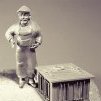 shipmodel got a reaction from kees de mol in Queen Anne's Revenge 1710 by shipmodel - FINISHED - 1/36 scale
Build Log 32 – crojack and lateen sail
Hi again. Being snowed in here in NYC had the silver lining of giving me some extra time to work on the model, so here is the next installment.
The next spar to be tackled was the crojack yard on the mizzen. Even as far back as 1710 it did not carry a sail, but was there to spread the foot of the mizzen topsail. It was shaped in the usual manner to the Budriot plans. Since it does not carry a sail the number of blocks stropped to it is reduced. There are sister blocks at the yardarms for the lifts and mizzen topsail sheets, pendant blocks for the braces and sheet blocks under the yard near the center. Since the yard is not lowered with any frequency, the parrell is replaced by a static collar, with the yard having a single large block in the center that will hold a sling that circles the masthead and supports the spar.
Here is the spar ready for mounting. The sling has been turned round the spar on one side and sized to the mast, leaving two long legs to be hitched round the spar and trimmed.
1
Here is the crojack yard mounted. In the enlarged portion you can see the collar hitched around the mast and spar and the sling running through the center block. According to Anderson (who I mistakenly referred to last time as Andersen) the French used the same lifts here as on the forward masts, while the English had already turned them into non-moving standing lifts since the yard did not move up or down.
14
In the above photo you might notice that there is now a railing around the poop deck/roof of the captain’s cabin. In testing the fit and location of the lateen sail I realized that there were no belaying points anywhere at the stern of the ship. Some belaying pins will be added to these rails, and other lighter lines can be hitched to the rails without pins. The posts will also give me some future locations for swivel gun mountings. They are 3 feet high in scale and made from steam bent pear, like the caprails.
15
The lateen spar is the simplest on the ship, even more so than the crojack yard. It tapers to both ends, but without a center octagonal section. There is a metal reinforcement and eyebolt at the lower end, but I never did discover the use for that fitting. A halyard line hitches to a point near the center of the spar, but a little towards the upper end. I left it loose until the yard was finally mounted.
Along the length of the spar are six small blocks. They are for the brailing lines that furl the sail and take the place of the clew, bunt and leach lines. They alternate single and double blocks, which will be made clear later.
16
The parrell is made up of “B” shaped spacers and black beads. The final piece is a small deadeye with only two holes.
17
Here is how it goes together. The deadeye is seized into the parrell line which doubles and laces through the spacers and beads. The lines are seized together again, although I took a shortcut and knotted them so I could adjust the placement later. The knot will be invisible in the final mounting. The lines then loop around the mast and the base of the halyard before threading through the deadeye. The parrell does not go around the lateen spar, but holds the halyard close to the mast instead. I read Anderson’s description of this many times before I began to understand it, and I am not really sure that I fully get it even now.
18
The lateen sail started by being laid out on the prepared sailcloth. All of the panel lines are parallel to the cloth threads, although the lower corner is not precisely a right angle.
19
Since the sail will be set with all its lines, I had to develop cringles at the edge of the sail as attachment points for the brailing lines. For my first attempt I cut small openings in the fold of the tabling, then laid the bolt rope into the fold and glued it as before. With a pin I reached in and pulled the bolt rope out of the opening. This did not work too well. The rope was fixed in place, so pulling it out made a visible kink in the edge of the sail.
20
For the next effort I worked the bolt rope into the cringle openings as I ironed down the tabling. This was a much more successful effort, although it took a significantly longer time.
21
Once the tabling was all down I turned the sail over and marked the panel seams. I found that the cloth was thin enough that a piece of white paper placed under the sail allowed me to see the panel seams through the cloth. Then the second seam was drawn on next to the first, but offset about 1/16”. When light shines through the cloth this double seam can be seen, but it is a subtle effect and may not be worth the effort.
22
Reinforcement panels were added to the back side of the sail, as indicated on the plans, then the sail was laced to the spar. I wanted to show a small aerodynamic curve to the sail, so I mounted it to a scrap cardboard box with tape at the corners of the spar and a line at the clew of the sail that was held with a clip so the curve could be adjusted.
23
I painted the sail with matte finish to stiffen it and laid in a folded plastic bag of rice to hold the curve as the finish dried.
24
As it turned out, this was not a successful effort. There is too much rice in the bag and the excess weight deformed the sail too much. I might have been able to live with this, but at this point I realized that the entire sail was too small. I had taken the dimensions of the spar from a digitized scan of the rigging plans that I had not double checked. It was two inches short. Even that I might have lived with, but coupled with the ragged cringles and the excess curve, I decided to scrap the sail and start again.
I saved the stropped brail blocks and the metal end fittings, but made a new spar and sail, which came out satisfactory. Here it is being curved and stiffened. Note how little rice it took to give the sail the curve that I wanted.
25
Once stiffened the sail was suspended by its upper corner and the reefing points were laced through holes in the reef band. There are knots on the back side which were glued into the holes, then the points were painted with matte finish and draped down on both sides.
26
The brailing lines were attached to the cringles then run up, diagonally, to the brail blocks. The first line, at the top, goes through a single block, then through the inside hole of the second, double block. The second line goes through the other hole of the double block, then both lines go together to a belaying point. Here they are coiled and taped together with a small clip to keep them from tangling until needed. The remaining brail lines are set up in similar pairs.
27
This photo was taken without a flash as it will normally be seen, with the light shining through the sail, making visible the doubled panel lines, reef points, and sail reinforcements.
28
A large single block was attached to the clew and a pair of single blocks on a short pendant to the lower end of the spar. Here it is, mounted. At the upper end of the spar a set of blocks on bridles leads the mizzen lift to a block at the masthead, then down to a belaying point on the rail.
29
Here it is from the windward side. I am not really happy with the look of the lift bridles. They are attached to the spar where both Anderson and Budriot indicate, but once tension was put on them they took on this pattern, not the more symmetrical one from the drawings.
30
Here is how the halyard and parrell came out, as seen from forward and aft. I am not happy with the bend in the halyard as is goes behind the crojack, but putting it in front results in an even bigger bend.
31
32
The final bit of rigging are the lines at the fore lower corner. Although they work like the braces of the square sails they are known, a bit confusingly, as the bowlines.
33
Here is the current status. The main topsail yard is clipped in place to get a sense of the size and shape of the sail. I can already see that the crowsfoot is going to be a problem.
34
Next, ad topsails per aspera . . .
Be well
Dan
-
 shipmodel got a reaction from ianmajor in Queen Anne's Revenge 1710 by shipmodel - FINISHED - 1/36 scale
Build Log 32 – crojack and lateen sail
Hi again. Being snowed in here in NYC had the silver lining of giving me some extra time to work on the model, so here is the next installment.
The next spar to be tackled was the crojack yard on the mizzen. Even as far back as 1710 it did not carry a sail, but was there to spread the foot of the mizzen topsail. It was shaped in the usual manner to the Budriot plans. Since it does not carry a sail the number of blocks stropped to it is reduced. There are sister blocks at the yardarms for the lifts and mizzen topsail sheets, pendant blocks for the braces and sheet blocks under the yard near the center. Since the yard is not lowered with any frequency, the parrell is replaced by a static collar, with the yard having a single large block in the center that will hold a sling that circles the masthead and supports the spar.
Here is the spar ready for mounting. The sling has been turned round the spar on one side and sized to the mast, leaving two long legs to be hitched round the spar and trimmed.
1
Here is the crojack yard mounted. In the enlarged portion you can see the collar hitched around the mast and spar and the sling running through the center block. According to Anderson (who I mistakenly referred to last time as Andersen) the French used the same lifts here as on the forward masts, while the English had already turned them into non-moving standing lifts since the yard did not move up or down.
14
In the above photo you might notice that there is now a railing around the poop deck/roof of the captain’s cabin. In testing the fit and location of the lateen sail I realized that there were no belaying points anywhere at the stern of the ship. Some belaying pins will be added to these rails, and other lighter lines can be hitched to the rails without pins. The posts will also give me some future locations for swivel gun mountings. They are 3 feet high in scale and made from steam bent pear, like the caprails.
15
The lateen spar is the simplest on the ship, even more so than the crojack yard. It tapers to both ends, but without a center octagonal section. There is a metal reinforcement and eyebolt at the lower end, but I never did discover the use for that fitting. A halyard line hitches to a point near the center of the spar, but a little towards the upper end. I left it loose until the yard was finally mounted.
Along the length of the spar are six small blocks. They are for the brailing lines that furl the sail and take the place of the clew, bunt and leach lines. They alternate single and double blocks, which will be made clear later.
16
The parrell is made up of “B” shaped spacers and black beads. The final piece is a small deadeye with only two holes.
17
Here is how it goes together. The deadeye is seized into the parrell line which doubles and laces through the spacers and beads. The lines are seized together again, although I took a shortcut and knotted them so I could adjust the placement later. The knot will be invisible in the final mounting. The lines then loop around the mast and the base of the halyard before threading through the deadeye. The parrell does not go around the lateen spar, but holds the halyard close to the mast instead. I read Anderson’s description of this many times before I began to understand it, and I am not really sure that I fully get it even now.
18
The lateen sail started by being laid out on the prepared sailcloth. All of the panel lines are parallel to the cloth threads, although the lower corner is not precisely a right angle.
19
Since the sail will be set with all its lines, I had to develop cringles at the edge of the sail as attachment points for the brailing lines. For my first attempt I cut small openings in the fold of the tabling, then laid the bolt rope into the fold and glued it as before. With a pin I reached in and pulled the bolt rope out of the opening. This did not work too well. The rope was fixed in place, so pulling it out made a visible kink in the edge of the sail.
20
For the next effort I worked the bolt rope into the cringle openings as I ironed down the tabling. This was a much more successful effort, although it took a significantly longer time.
21
Once the tabling was all down I turned the sail over and marked the panel seams. I found that the cloth was thin enough that a piece of white paper placed under the sail allowed me to see the panel seams through the cloth. Then the second seam was drawn on next to the first, but offset about 1/16”. When light shines through the cloth this double seam can be seen, but it is a subtle effect and may not be worth the effort.
22
Reinforcement panels were added to the back side of the sail, as indicated on the plans, then the sail was laced to the spar. I wanted to show a small aerodynamic curve to the sail, so I mounted it to a scrap cardboard box with tape at the corners of the spar and a line at the clew of the sail that was held with a clip so the curve could be adjusted.
23
I painted the sail with matte finish to stiffen it and laid in a folded plastic bag of rice to hold the curve as the finish dried.
24
As it turned out, this was not a successful effort. There is too much rice in the bag and the excess weight deformed the sail too much. I might have been able to live with this, but at this point I realized that the entire sail was too small. I had taken the dimensions of the spar from a digitized scan of the rigging plans that I had not double checked. It was two inches short. Even that I might have lived with, but coupled with the ragged cringles and the excess curve, I decided to scrap the sail and start again.
I saved the stropped brail blocks and the metal end fittings, but made a new spar and sail, which came out satisfactory. Here it is being curved and stiffened. Note how little rice it took to give the sail the curve that I wanted.
25
Once stiffened the sail was suspended by its upper corner and the reefing points were laced through holes in the reef band. There are knots on the back side which were glued into the holes, then the points were painted with matte finish and draped down on both sides.
26
The brailing lines were attached to the cringles then run up, diagonally, to the brail blocks. The first line, at the top, goes through a single block, then through the inside hole of the second, double block. The second line goes through the other hole of the double block, then both lines go together to a belaying point. Here they are coiled and taped together with a small clip to keep them from tangling until needed. The remaining brail lines are set up in similar pairs.
27
This photo was taken without a flash as it will normally be seen, with the light shining through the sail, making visible the doubled panel lines, reef points, and sail reinforcements.
28
A large single block was attached to the clew and a pair of single blocks on a short pendant to the lower end of the spar. Here it is, mounted. At the upper end of the spar a set of blocks on bridles leads the mizzen lift to a block at the masthead, then down to a belaying point on the rail.
29
Here it is from the windward side. I am not really happy with the look of the lift bridles. They are attached to the spar where both Anderson and Budriot indicate, but once tension was put on them they took on this pattern, not the more symmetrical one from the drawings.
30
Here is how the halyard and parrell came out, as seen from forward and aft. I am not happy with the bend in the halyard as is goes behind the crojack, but putting it in front results in an even bigger bend.
31
32
The final bit of rigging are the lines at the fore lower corner. Although they work like the braces of the square sails they are known, a bit confusingly, as the bowlines.
33
Here is the current status. The main topsail yard is clipped in place to get a sense of the size and shape of the sail. I can already see that the crowsfoot is going to be a problem.
34
Next, ad topsails per aspera . . .
Be well
Dan
-
shipmodel got a reaction from tkay11 in Queen Anne's Revenge 1710 by shipmodel - FINISHED - 1/36 scale
Build Log 32 – crojack and lateen sail
Hi again. Being snowed in here in NYC had the silver lining of giving me some extra time to work on the model, so here is the next installment.
The next spar to be tackled was the crojack yard on the mizzen. Even as far back as 1710 it did not carry a sail, but was there to spread the foot of the mizzen topsail. It was shaped in the usual manner to the Budriot plans. Since it does not carry a sail the number of blocks stropped to it is reduced. There are sister blocks at the yardarms for the lifts and mizzen topsail sheets, pendant blocks for the braces and sheet blocks under the yard near the center. Since the yard is not lowered with any frequency, the parrell is replaced by a static collar, with the yard having a single large block in the center that will hold a sling that circles the masthead and supports the spar.
Here is the spar ready for mounting. The sling has been turned round the spar on one side and sized to the mast, leaving two long legs to be hitched round the spar and trimmed.
1
Here is the crojack yard mounted. In the enlarged portion you can see the collar hitched around the mast and spar and the sling running through the center block. According to Anderson (who I mistakenly referred to last time as Andersen) the French used the same lifts here as on the forward masts, while the English had already turned them into non-moving standing lifts since the yard did not move up or down.
14
In the above photo you might notice that there is now a railing around the poop deck/roof of the captain’s cabin. In testing the fit and location of the lateen sail I realized that there were no belaying points anywhere at the stern of the ship. Some belaying pins will be added to these rails, and other lighter lines can be hitched to the rails without pins. The posts will also give me some future locations for swivel gun mountings. They are 3 feet high in scale and made from steam bent pear, like the caprails.
15
The lateen spar is the simplest on the ship, even more so than the crojack yard. It tapers to both ends, but without a center octagonal section. There is a metal reinforcement and eyebolt at the lower end, but I never did discover the use for that fitting. A halyard line hitches to a point near the center of the spar, but a little towards the upper end. I left it loose until the yard was finally mounted.
Along the length of the spar are six small blocks. They are for the brailing lines that furl the sail and take the place of the clew, bunt and leach lines. They alternate single and double blocks, which will be made clear later.
16
The parrell is made up of “B” shaped spacers and black beads. The final piece is a small deadeye with only two holes.
17
Here is how it goes together. The deadeye is seized into the parrell line which doubles and laces through the spacers and beads. The lines are seized together again, although I took a shortcut and knotted them so I could adjust the placement later. The knot will be invisible in the final mounting. The lines then loop around the mast and the base of the halyard before threading through the deadeye. The parrell does not go around the lateen spar, but holds the halyard close to the mast instead. I read Anderson’s description of this many times before I began to understand it, and I am not really sure that I fully get it even now.
18
The lateen sail started by being laid out on the prepared sailcloth. All of the panel lines are parallel to the cloth threads, although the lower corner is not precisely a right angle.
19
Since the sail will be set with all its lines, I had to develop cringles at the edge of the sail as attachment points for the brailing lines. For my first attempt I cut small openings in the fold of the tabling, then laid the bolt rope into the fold and glued it as before. With a pin I reached in and pulled the bolt rope out of the opening. This did not work too well. The rope was fixed in place, so pulling it out made a visible kink in the edge of the sail.
20
For the next effort I worked the bolt rope into the cringle openings as I ironed down the tabling. This was a much more successful effort, although it took a significantly longer time.
21
Once the tabling was all down I turned the sail over and marked the panel seams. I found that the cloth was thin enough that a piece of white paper placed under the sail allowed me to see the panel seams through the cloth. Then the second seam was drawn on next to the first, but offset about 1/16”. When light shines through the cloth this double seam can be seen, but it is a subtle effect and may not be worth the effort.
22
Reinforcement panels were added to the back side of the sail, as indicated on the plans, then the sail was laced to the spar. I wanted to show a small aerodynamic curve to the sail, so I mounted it to a scrap cardboard box with tape at the corners of the spar and a line at the clew of the sail that was held with a clip so the curve could be adjusted.
23
I painted the sail with matte finish to stiffen it and laid in a folded plastic bag of rice to hold the curve as the finish dried.
24
As it turned out, this was not a successful effort. There is too much rice in the bag and the excess weight deformed the sail too much. I might have been able to live with this, but at this point I realized that the entire sail was too small. I had taken the dimensions of the spar from a digitized scan of the rigging plans that I had not double checked. It was two inches short. Even that I might have lived with, but coupled with the ragged cringles and the excess curve, I decided to scrap the sail and start again.
I saved the stropped brail blocks and the metal end fittings, but made a new spar and sail, which came out satisfactory. Here it is being curved and stiffened. Note how little rice it took to give the sail the curve that I wanted.
25
Once stiffened the sail was suspended by its upper corner and the reefing points were laced through holes in the reef band. There are knots on the back side which were glued into the holes, then the points were painted with matte finish and draped down on both sides.
26
The brailing lines were attached to the cringles then run up, diagonally, to the brail blocks. The first line, at the top, goes through a single block, then through the inside hole of the second, double block. The second line goes through the other hole of the double block, then both lines go together to a belaying point. Here they are coiled and taped together with a small clip to keep them from tangling until needed. The remaining brail lines are set up in similar pairs.
27
This photo was taken without a flash as it will normally be seen, with the light shining through the sail, making visible the doubled panel lines, reef points, and sail reinforcements.
28
A large single block was attached to the clew and a pair of single blocks on a short pendant to the lower end of the spar. Here it is, mounted. At the upper end of the spar a set of blocks on bridles leads the mizzen lift to a block at the masthead, then down to a belaying point on the rail.
29
Here it is from the windward side. I am not really happy with the look of the lift bridles. They are attached to the spar where both Anderson and Budriot indicate, but once tension was put on them they took on this pattern, not the more symmetrical one from the drawings.
30
Here is how the halyard and parrell came out, as seen from forward and aft. I am not happy with the bend in the halyard as is goes behind the crojack, but putting it in front results in an even bigger bend.
31
32
The final bit of rigging are the lines at the fore lower corner. Although they work like the braces of the square sails they are known, a bit confusingly, as the bowlines.
33
Here is the current status. The main topsail yard is clipped in place to get a sense of the size and shape of the sail. I can already see that the crowsfoot is going to be a problem.
34
Next, ad topsails per aspera . . .
Be well
Dan