


shipmodel
-
Posts
908 -
Joined
-
Last visited
Reputation Activity
-

 shipmodel got a reaction from mtaylor in Queen Anne's Revenge 1710 by shipmodel - FINISHED - 1/36 scale
Hi all - This is off topic, If you know where it should be posted, let me know. I recently read a thread which asked for a recommendation for an illustrated glossary of ship terms. Unfortunately, I can't find it now. In any case, one of the best general introductions that I have run across is: "The Visual Dictionary of Ships and Sailing" produced by Eyewitness Visual Dictionaries. It is a slim book but covers topics from the first boats to modern underwater diving gear and ROVs. Obviously, it can's do justice to everything, but does an excellent job for the things that it selects. The best part is that many topics are illustrated with either the actual object or photographs of top quality models. Hope that helps. Dan -
 shipmodel got a reaction from popash42 in Queen Anne's Revenge 1710 by shipmodel - FINISHED - 1/36 scale
Hi again to everyone following this log. Thanks for all the support, comments and likes.
Here is the work that has happened in the last week. I usually put two or more weeks of work into a log entry, but I am going on vacation with the family all of next week, and didn’t want to postpone it.
At the end of the last entry I noticed some symmetry problems at the bow. The thin molding was low on the port side, and the starboard bulwark was too high.
Here I have corrected the problems. I think that the fix is satisfactory, but I will continue to examine the model to see if there are any others that need work.
Next I started on the planking for the gun deck where it will be visible in the waist. The insides of the bulwarks were planked just like the outer surface of the hull, with individual planks of birch veneer glued on with contact cement. Planks were trimmed to cover the gunport frames and linings. Treenail fasteners were done in the usual manner.
The planking of the deck in the waist is a little different. Budriot’s plans indicate that the central section of the deck was made up of thicker planks than the rest of the deck. The outermost of these planks were let into the deck beams beneath and are known as binding strakes. They helped lock the deck to the deck beams and strengthened the entire core of the ship.
On the model I did not lock them into the structure so they are not binding strakes, but they are made of thicker stuff than the planks. Examination of photos of contemporary French models in the Musee de la Marine (Budriot, Historic Ship Models) indicates a pretty consistent look to this section of the deck. The binding strakes and the gratings are dark, even painted black, while the central planking is lighter and matches the color of the rest of the deck planking.
I started with the gratings which I made earlier. These were made on the English pattern, so I crowned them and set them down into the raised strakes so they are nearly flush. These are the first of the early pieces to be permanently attached to the model. The binding strakes are cherry, like the coamings for the gratings, while the central planking is holly. This is a veneer and was glued to crowned sections of basswood to match the curve of the gratings.
Once this section was in place and pinned to the deck substrate, I drew the locations for the deck beams, starting with those at each end of the gratings and filling in from there. They laid out with a pretty consistent pattern of 4 scale feet center to center.
Now I used the holly veneer to plank outward from the center section. I was going to saw up a bunch of individual planks and do the deck as I had done the outer surface of the hull. But then I decided to try using one large sheet of veneer with the planks marked and scribed on. After a satisfactory test piece was made I decided to go for it.
A paper pattern was made that fit the area from the binding strake to the base of the bulwark. This was laid out onto a piece of holly veneer, but not cut. Using a long metal ruler as a straightedge a series of 6mm wide planks were laid out on the wood. With the veneer clamped under the ruler a pencil line was drawn with a 0.5mm mechanical pencil so all the lines would be a consistent width. Without unclamping I scribed the line into the wood with two light passes using the back of a #10 blade. The markings were made permanent with two coats of spray satin finish.
With the planks lined out I cut and trimmed the veneer piece until it fit snugly into the space from binding strake to bulwark. I test fit the piece in place and lightly marked the beam locations onto the veneer. Using the straightedge and a small square the butt joints were marked out, penciled and scribed as before. I used a 3-step pattern with a 1-3-2-4 stagger. I don’t know if this is historically correct for French ships of the period, but it looks right.
After a final sanding to smooth the deck substrate several coats of thinned contact cement were painted onto the deck and the veneer piece. When dry the piece was laid in place and burnished down to the substrate. This is a permanent bond, like a kitchen counter, but the treenails that will be installed doubly guarantee adhesion.
At the base of the bulwarks a margin plank, finish plank, and chamfered waterway were installed. They are cherry and contrast nicely with the birch of the bulwark and the holly of the deck.
Now all the fastening holes could be drilled. Careening the model in the cradles gave me access without straining.
As with the hull planks, I used square treenail sticks pressed into round holes and clipped short, leaving just nubs of wood above the surface of the planks.
When all the holes were filled they were painted with dilute white glue. When the glue dried the nubs were cut off flush with a small sharp chisel. The fastenings are birch which subtly contrasts with the holly without becoming overbearing. The fastenings in the cherry binding strakes were made of walnut, also for a bit of contrast.
With the waist planked it will soon be time to work on the upper decks. Here I have laid up the substrates for the three sections. They are made up of two layers of 1/16” basswood glued over a curved form. The laminated pieces held their shapes quite well after the glue dried. Paper patterns were used to get the right outlines. The pieces were cut on the band saw and refined with a bench disc sander.
With the deck pieces temporarily installed I fitted out the waist with cannon, the ship’s boat, and my figures.
I don’t see anything when I examine the model or in the photos that looks obviously wrong, but my eyes are getting old and I am a bit biased. If anyone sees anything, please tell me now while I can still get at it to change it.
Thanks
Dan
-
shipmodel got a reaction from popash42 in Queen Anne's Revenge 1710 by shipmodel - FINISHED - 1/36 scale
Hi to all, and thanks for the comments and questions. Please keep them coming. Many eyes and brains will always spot problems that one set will not see until it is too late to easily correct them.
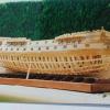
The last entry ended with the hull planked and the upper works painted as requested by the museum.
The next task was to install all of the plank fastenings. French practice at the time, as far as can be determined 300 years later, was to alternate wooden treenails with iron spikes. That is, each time a plank crossed a frame there were two fasteners, one iron, one wood, set at a diagonal to each other. At the neighboring frames to either side the pattern was flipped over, so if the first frame had a treenail at the top, the neighbor had a spike at the top. Butt joints between planks were secured with four fasteners, two of each kind, also set diagonally.
Here is what the finished pattern looks like on the model.
The experiments that I did on the practice gun station led me to the following sequence, which got the thousands of fasteners done in a reasonable amount of time:
After installation, the planks were given a coat of pale stain, then a first clear coat to protect them from glue spots and dirt. This coating also helped when it came time to remove the pencil lines that were drawn to indicate the frame locations under the planks. Without it the graphite gets into the grain of the wood and is really hard to remove.
Next, the holes for all of the treenails were drilled. I used the cordless Dremel 1000 which has a pistol shape. It lets me simply point at the desired spot and just lean forward to make a 1/8” deep hole. With some good music in the background and a repetitive chant under my breath, I would develop a rhythm that made the chore go pretty quickly.
Multiple strips of treenail stock were cut from cherry veneer on the Preac. They were 0.025” square, or about 0.035” on the diagonal. The holes were drilled with a 0.0325” bit so that the strips could be inserted to the bottom of the hole with a friction fit and then clipped or snapped off. Again, music made the task bearable.
Once all the holes were filled they were painted with heavily diluted white glue. It was thin enough to wick down the sides of the strips to the bottom of the holes. This not only secured the treenails to the planks and the hull, but it swelled the fibers so that the square strips now filled the entire round holes. No lengthy, fiddly pulling through a drawplate was necessary. This is a good thing, because I am really terrible at it. I usually end up with more splinters on the floor than treenails in the cup.
Once the glue dried the stubs of the treenails were cut close to the plank surface using a small chisel, then they were sanded flush, which also removed the pencil lines.
Now the holes for the spikes could all be drilled, using the treenail locations as the guide. This time the holes were only 0.025” diameter and were filled with 0.022” soft iron wire. Clippers were used to cut them as close as possible to the plank surface. Here I am filling the holes in the planks of the counter with the model turned upside down.
Once a large section of spikes were inserted they were peened or pressed into the hull until they were almost flush with the surface. Then they were painted with a second clear coat of finish. This not only secured the spikes from coming out, but darkened the tops of the treenails so the cherry stood out from the birch of the planking.
Even without doing the fasteners under the painted sections there are over 3,000 fasteners in the hull. Using this sequence, the fasteners were done, start to finish, in three 6-hour workdays.
With the planking done, the gunport linings were fitted using the square wooden tube as explained in the earlier log for the gun station. Here is how it came out after staining to match the planking.
And here are two cannon protruding from their ports as they will be in the finished model.
As we all do, I use the photographs to check my work. Some things seem to appear only under the light of a flash. Here I am checking the symmetry of the bow. It looks generally good, but there are two problems that I have to correct.
First, the thin molding just above the wale does not match, port to starboard. The port side is about 1/16” low at the stem. It will be pried up and relocated before re-gluing and final pinning with metal spikes.
The second problem is less clear. The cap of the starboard bow is higher than its corresponding shape on the port side. You can see it a bit better with the photo taken from a lower angle.
The cap molding will be removed, the shape adjusted, and the molding replaced. Otherwise, I am happy with the symmetry of the hull both here at the bow, and here at the stern.
You can see that the two ports in the counter have been detailed. Although the hull details will mostly be done later, it was easier to do this area while I could still turn the model over and work on it upside down.
The ports have two half-lids with four hinge straps each and a lanyard to open the top half. These were made in the same way as the hinge straps for the companionway that was shown in an earlier log. I used my orthodontic pliers to bend 1/16” brass strips which were then drilled and chemically blackened before gluing and pinning with wire. The four rings above the lower molding are for the preventer chains that will attach to the smaller rings on the sides of the rudder just above the white stuff.
The rudder itself is built up from two pieces of cherry which were cut, shaped and tapered according to the plans. The gudgeons and pintles were bent up from 3/32” wide brass strips, blackened and drilled, then secured in the usual manner to the rudder and the hull.
At the transom you can see the paper pattern for the latest iteration of the stern gallery of windows. This was originally taken from the Mercure plans, but heavily modified to fit the internal deck layout of the Advice Prize. It was pushed, prodded, resized, and details were changed and changed back again in Photoshop before being printed out to test size and suitability against the spacing and layout of the hull moldings. More changes will be made, I’m sure, before I am completely happy with it and can start cutting wood.
I’m having to do a lot of testing like this to reconcile the shape and layout of the Advice Prize with the details from Le Mercure. Here I have installed rough place-holders for the quarterdeck and forecastle deck so I can plan the layout in the waist.
The museum asked that one broadside of cannon be mounted through the ports with the lids opened. The other side will have the guns “housed”. But when I tested the layout of the guns with their muzzles hard against the bulwark it was clear that there would be no room for the ship’s boat on the centerline. A check against the plans confirmed that this was so.
Instead, I suggested that the cannon not in use be housed fore and aft against the bulwark. This is one way that it was done on the real ships. Now, with the opposite cannon through the port, there is enough clearance for the boat and to work the guns.
And here is what the broadside looks like before the gunport lids and the rest of the hull details are installed.
Finally, lest you think that I work in a clean and orderly manner as implied in the heavily cropped photos in the log, here is our dining room table on a fairly neat day. It looks much worse on a daily basis and for months at a time.
I can’t say enough about the forbearance and good humor of my wife. Without her this would not be remotely possible. I can only wish you all the same happiness with your spouse or significant other.
Be well
Dan
-
.thumb.jpeg.fc5d633a7b34428fcf19419a73d56d55.jpeg) shipmodel got a reaction from EricWilliamMarshall in Queen Anne's Revenge 1710 by shipmodel - FINISHED - 1/36 scale
shipmodel got a reaction from EricWilliamMarshall in Queen Anne's Revenge 1710 by shipmodel - FINISHED - 1/36 scale
Hi to all, and thanks for the comments and questions. Please keep them coming. Many eyes and brains will always spot problems that one set will not see until it is too late to easily correct them.
The last entry ended with the hull planked and the upper works painted as requested by the museum.
The next task was to install all of the plank fastenings. French practice at the time, as far as can be determined 300 years later, was to alternate wooden treenails with iron spikes. That is, each time a plank crossed a frame there were two fasteners, one iron, one wood, set at a diagonal to each other. At the neighboring frames to either side the pattern was flipped over, so if the first frame had a treenail at the top, the neighbor had a spike at the top. Butt joints between planks were secured with four fasteners, two of each kind, also set diagonally.
Here is what the finished pattern looks like on the model.
The experiments that I did on the practice gun station led me to the following sequence, which got the thousands of fasteners done in a reasonable amount of time:
After installation, the planks were given a coat of pale stain, then a first clear coat to protect them from glue spots and dirt. This coating also helped when it came time to remove the pencil lines that were drawn to indicate the frame locations under the planks. Without it the graphite gets into the grain of the wood and is really hard to remove.
Next, the holes for all of the treenails were drilled. I used the cordless Dremel 1000 which has a pistol shape. It lets me simply point at the desired spot and just lean forward to make a 1/8” deep hole. With some good music in the background and a repetitive chant under my breath, I would develop a rhythm that made the chore go pretty quickly.
Multiple strips of treenail stock were cut from cherry veneer on the Preac. They were 0.025” square, or about 0.035” on the diagonal. The holes were drilled with a 0.0325” bit so that the strips could be inserted to the bottom of the hole with a friction fit and then clipped or snapped off. Again, music made the task bearable.
Once all the holes were filled they were painted with heavily diluted white glue. It was thin enough to wick down the sides of the strips to the bottom of the holes. This not only secured the treenails to the planks and the hull, but it swelled the fibers so that the square strips now filled the entire round holes. No lengthy, fiddly pulling through a drawplate was necessary. This is a good thing, because I am really terrible at it. I usually end up with more splinters on the floor than treenails in the cup.
Once the glue dried the stubs of the treenails were cut close to the plank surface using a small chisel, then they were sanded flush, which also removed the pencil lines.
Now the holes for the spikes could all be drilled, using the treenail locations as the guide. This time the holes were only 0.025” diameter and were filled with 0.022” soft iron wire. Clippers were used to cut them as close as possible to the plank surface. Here I am filling the holes in the planks of the counter with the model turned upside down.
Once a large section of spikes were inserted they were peened or pressed into the hull until they were almost flush with the surface. Then they were painted with a second clear coat of finish. This not only secured the spikes from coming out, but darkened the tops of the treenails so the cherry stood out from the birch of the planking.
Even without doing the fasteners under the painted sections there are over 3,000 fasteners in the hull. Using this sequence, the fasteners were done, start to finish, in three 6-hour workdays.
With the planking done, the gunport linings were fitted using the square wooden tube as explained in the earlier log for the gun station. Here is how it came out after staining to match the planking.
And here are two cannon protruding from their ports as they will be in the finished model.
As we all do, I use the photographs to check my work. Some things seem to appear only under the light of a flash. Here I am checking the symmetry of the bow. It looks generally good, but there are two problems that I have to correct.
First, the thin molding just above the wale does not match, port to starboard. The port side is about 1/16” low at the stem. It will be pried up and relocated before re-gluing and final pinning with metal spikes.
The second problem is less clear. The cap of the starboard bow is higher than its corresponding shape on the port side. You can see it a bit better with the photo taken from a lower angle.
The cap molding will be removed, the shape adjusted, and the molding replaced. Otherwise, I am happy with the symmetry of the hull both here at the bow, and here at the stern.
You can see that the two ports in the counter have been detailed. Although the hull details will mostly be done later, it was easier to do this area while I could still turn the model over and work on it upside down.
The ports have two half-lids with four hinge straps each and a lanyard to open the top half. These were made in the same way as the hinge straps for the companionway that was shown in an earlier log. I used my orthodontic pliers to bend 1/16” brass strips which were then drilled and chemically blackened before gluing and pinning with wire. The four rings above the lower molding are for the preventer chains that will attach to the smaller rings on the sides of the rudder just above the white stuff.
The rudder itself is built up from two pieces of cherry which were cut, shaped and tapered according to the plans. The gudgeons and pintles were bent up from 3/32” wide brass strips, blackened and drilled, then secured in the usual manner to the rudder and the hull.
At the transom you can see the paper pattern for the latest iteration of the stern gallery of windows. This was originally taken from the Mercure plans, but heavily modified to fit the internal deck layout of the Advice Prize. It was pushed, prodded, resized, and details were changed and changed back again in Photoshop before being printed out to test size and suitability against the spacing and layout of the hull moldings. More changes will be made, I’m sure, before I am completely happy with it and can start cutting wood.
I’m having to do a lot of testing like this to reconcile the shape and layout of the Advice Prize with the details from Le Mercure. Here I have installed rough place-holders for the quarterdeck and forecastle deck so I can plan the layout in the waist.
The museum asked that one broadside of cannon be mounted through the ports with the lids opened. The other side will have the guns “housed”. But when I tested the layout of the guns with their muzzles hard against the bulwark it was clear that there would be no room for the ship’s boat on the centerline. A check against the plans confirmed that this was so.
Instead, I suggested that the cannon not in use be housed fore and aft against the bulwark. This is one way that it was done on the real ships. Now, with the opposite cannon through the port, there is enough clearance for the boat and to work the guns.
And here is what the broadside looks like before the gunport lids and the rest of the hull details are installed.
Finally, lest you think that I work in a clean and orderly manner as implied in the heavily cropped photos in the log, here is our dining room table on a fairly neat day. It looks much worse on a daily basis and for months at a time.
I can’t say enough about the forbearance and good humor of my wife. Without her this would not be remotely possible. I can only wish you all the same happiness with your spouse or significant other.
Be well
Dan
-
shipmodel got a reaction from EricWilliamMarshall in Queen Anne's Revenge 1710 by shipmodel - FINISHED - 1/36 scale
Hi again to everyone following this log. Thanks for all the support, comments and likes.
Here is the work that has happened in the last week. I usually put two or more weeks of work into a log entry, but I am going on vacation with the family all of next week, and didn’t want to postpone it.
At the end of the last entry I noticed some symmetry problems at the bow. The thin molding was low on the port side, and the starboard bulwark was too high.
Here I have corrected the problems. I think that the fix is satisfactory, but I will continue to examine the model to see if there are any others that need work.
Next I started on the planking for the gun deck where it will be visible in the waist. The insides of the bulwarks were planked just like the outer surface of the hull, with individual planks of birch veneer glued on with contact cement. Planks were trimmed to cover the gunport frames and linings. Treenail fasteners were done in the usual manner.
The planking of the deck in the waist is a little different. Budriot’s plans indicate that the central section of the deck was made up of thicker planks than the rest of the deck. The outermost of these planks were let into the deck beams beneath and are known as binding strakes. They helped lock the deck to the deck beams and strengthened the entire core of the ship.
On the model I did not lock them into the structure so they are not binding strakes, but they are made of thicker stuff than the planks. Examination of photos of contemporary French models in the Musee de la Marine (Budriot, Historic Ship Models) indicates a pretty consistent look to this section of the deck. The binding strakes and the gratings are dark, even painted black, while the central planking is lighter and matches the color of the rest of the deck planking.
I started with the gratings which I made earlier. These were made on the English pattern, so I crowned them and set them down into the raised strakes so they are nearly flush. These are the first of the early pieces to be permanently attached to the model. The binding strakes are cherry, like the coamings for the gratings, while the central planking is holly. This is a veneer and was glued to crowned sections of basswood to match the curve of the gratings.
Once this section was in place and pinned to the deck substrate, I drew the locations for the deck beams, starting with those at each end of the gratings and filling in from there. They laid out with a pretty consistent pattern of 4 scale feet center to center.
Now I used the holly veneer to plank outward from the center section. I was going to saw up a bunch of individual planks and do the deck as I had done the outer surface of the hull. But then I decided to try using one large sheet of veneer with the planks marked and scribed on. After a satisfactory test piece was made I decided to go for it.
A paper pattern was made that fit the area from the binding strake to the base of the bulwark. This was laid out onto a piece of holly veneer, but not cut. Using a long metal ruler as a straightedge a series of 6mm wide planks were laid out on the wood. With the veneer clamped under the ruler a pencil line was drawn with a 0.5mm mechanical pencil so all the lines would be a consistent width. Without unclamping I scribed the line into the wood with two light passes using the back of a #10 blade. The markings were made permanent with two coats of spray satin finish.
With the planks lined out I cut and trimmed the veneer piece until it fit snugly into the space from binding strake to bulwark. I test fit the piece in place and lightly marked the beam locations onto the veneer. Using the straightedge and a small square the butt joints were marked out, penciled and scribed as before. I used a 3-step pattern with a 1-3-2-4 stagger. I don’t know if this is historically correct for French ships of the period, but it looks right.
After a final sanding to smooth the deck substrate several coats of thinned contact cement were painted onto the deck and the veneer piece. When dry the piece was laid in place and burnished down to the substrate. This is a permanent bond, like a kitchen counter, but the treenails that will be installed doubly guarantee adhesion.
At the base of the bulwarks a margin plank, finish plank, and chamfered waterway were installed. They are cherry and contrast nicely with the birch of the bulwark and the holly of the deck.
Now all the fastening holes could be drilled. Careening the model in the cradles gave me access without straining.
As with the hull planks, I used square treenail sticks pressed into round holes and clipped short, leaving just nubs of wood above the surface of the planks.
When all the holes were filled they were painted with dilute white glue. When the glue dried the nubs were cut off flush with a small sharp chisel. The fastenings are birch which subtly contrasts with the holly without becoming overbearing. The fastenings in the cherry binding strakes were made of walnut, also for a bit of contrast.
With the waist planked it will soon be time to work on the upper decks. Here I have laid up the substrates for the three sections. They are made up of two layers of 1/16” basswood glued over a curved form. The laminated pieces held their shapes quite well after the glue dried. Paper patterns were used to get the right outlines. The pieces were cut on the band saw and refined with a bench disc sander.
With the deck pieces temporarily installed I fitted out the waist with cannon, the ship’s boat, and my figures.
I don’t see anything when I examine the model or in the photos that looks obviously wrong, but my eyes are getting old and I am a bit biased. If anyone sees anything, please tell me now while I can still get at it to change it.
Thanks
Dan
-
 shipmodel got a reaction from Ponto in Queen Anne's Revenge 1710 by shipmodel - FINISHED - 1/36 scale
Hi again to everyone following this log. Thanks for all the support, comments and likes.
Here is the work that has happened in the last week. I usually put two or more weeks of work into a log entry, but I am going on vacation with the family all of next week, and didn’t want to postpone it.
At the end of the last entry I noticed some symmetry problems at the bow. The thin molding was low on the port side, and the starboard bulwark was too high.
Here I have corrected the problems. I think that the fix is satisfactory, but I will continue to examine the model to see if there are any others that need work.
Next I started on the planking for the gun deck where it will be visible in the waist. The insides of the bulwarks were planked just like the outer surface of the hull, with individual planks of birch veneer glued on with contact cement. Planks were trimmed to cover the gunport frames and linings. Treenail fasteners were done in the usual manner.
The planking of the deck in the waist is a little different. Budriot’s plans indicate that the central section of the deck was made up of thicker planks than the rest of the deck. The outermost of these planks were let into the deck beams beneath and are known as binding strakes. They helped lock the deck to the deck beams and strengthened the entire core of the ship.
On the model I did not lock them into the structure so they are not binding strakes, but they are made of thicker stuff than the planks. Examination of photos of contemporary French models in the Musee de la Marine (Budriot, Historic Ship Models) indicates a pretty consistent look to this section of the deck. The binding strakes and the gratings are dark, even painted black, while the central planking is lighter and matches the color of the rest of the deck planking.
I started with the gratings which I made earlier. These were made on the English pattern, so I crowned them and set them down into the raised strakes so they are nearly flush. These are the first of the early pieces to be permanently attached to the model. The binding strakes are cherry, like the coamings for the gratings, while the central planking is holly. This is a veneer and was glued to crowned sections of basswood to match the curve of the gratings.
Once this section was in place and pinned to the deck substrate, I drew the locations for the deck beams, starting with those at each end of the gratings and filling in from there. They laid out with a pretty consistent pattern of 4 scale feet center to center.
Now I used the holly veneer to plank outward from the center section. I was going to saw up a bunch of individual planks and do the deck as I had done the outer surface of the hull. But then I decided to try using one large sheet of veneer with the planks marked and scribed on. After a satisfactory test piece was made I decided to go for it.
A paper pattern was made that fit the area from the binding strake to the base of the bulwark. This was laid out onto a piece of holly veneer, but not cut. Using a long metal ruler as a straightedge a series of 6mm wide planks were laid out on the wood. With the veneer clamped under the ruler a pencil line was drawn with a 0.5mm mechanical pencil so all the lines would be a consistent width. Without unclamping I scribed the line into the wood with two light passes using the back of a #10 blade. The markings were made permanent with two coats of spray satin finish.
With the planks lined out I cut and trimmed the veneer piece until it fit snugly into the space from binding strake to bulwark. I test fit the piece in place and lightly marked the beam locations onto the veneer. Using the straightedge and a small square the butt joints were marked out, penciled and scribed as before. I used a 3-step pattern with a 1-3-2-4 stagger. I don’t know if this is historically correct for French ships of the period, but it looks right.
After a final sanding to smooth the deck substrate several coats of thinned contact cement were painted onto the deck and the veneer piece. When dry the piece was laid in place and burnished down to the substrate. This is a permanent bond, like a kitchen counter, but the treenails that will be installed doubly guarantee adhesion.
At the base of the bulwarks a margin plank, finish plank, and chamfered waterway were installed. They are cherry and contrast nicely with the birch of the bulwark and the holly of the deck.
Now all the fastening holes could be drilled. Careening the model in the cradles gave me access without straining.
As with the hull planks, I used square treenail sticks pressed into round holes and clipped short, leaving just nubs of wood above the surface of the planks.
When all the holes were filled they were painted with dilute white glue. When the glue dried the nubs were cut off flush with a small sharp chisel. The fastenings are birch which subtly contrasts with the holly without becoming overbearing. The fastenings in the cherry binding strakes were made of walnut, also for a bit of contrast.
With the waist planked it will soon be time to work on the upper decks. Here I have laid up the substrates for the three sections. They are made up of two layers of 1/16” basswood glued over a curved form. The laminated pieces held their shapes quite well after the glue dried. Paper patterns were used to get the right outlines. The pieces were cut on the band saw and refined with a bench disc sander.
With the deck pieces temporarily installed I fitted out the waist with cannon, the ship’s boat, and my figures.
I don’t see anything when I examine the model or in the photos that looks obviously wrong, but my eyes are getting old and I am a bit biased. If anyone sees anything, please tell me now while I can still get at it to change it.
Thanks
Dan
-
 shipmodel got a reaction from AndyHall in Queen Anne's Revenge 1710 by shipmodel - FINISHED - 1/36 scale
Hi to all, and thanks for the comments and questions. Please keep them coming. Many eyes and brains will always spot problems that one set will not see until it is too late to easily correct them.
The last entry ended with the hull planked and the upper works painted as requested by the museum.
The next task was to install all of the plank fastenings. French practice at the time, as far as can be determined 300 years later, was to alternate wooden treenails with iron spikes. That is, each time a plank crossed a frame there were two fasteners, one iron, one wood, set at a diagonal to each other. At the neighboring frames to either side the pattern was flipped over, so if the first frame had a treenail at the top, the neighbor had a spike at the top. Butt joints between planks were secured with four fasteners, two of each kind, also set diagonally.
Here is what the finished pattern looks like on the model.
The experiments that I did on the practice gun station led me to the following sequence, which got the thousands of fasteners done in a reasonable amount of time:
After installation, the planks were given a coat of pale stain, then a first clear coat to protect them from glue spots and dirt. This coating also helped when it came time to remove the pencil lines that were drawn to indicate the frame locations under the planks. Without it the graphite gets into the grain of the wood and is really hard to remove.
Next, the holes for all of the treenails were drilled. I used the cordless Dremel 1000 which has a pistol shape. It lets me simply point at the desired spot and just lean forward to make a 1/8” deep hole. With some good music in the background and a repetitive chant under my breath, I would develop a rhythm that made the chore go pretty quickly.
Multiple strips of treenail stock were cut from cherry veneer on the Preac. They were 0.025” square, or about 0.035” on the diagonal. The holes were drilled with a 0.0325” bit so that the strips could be inserted to the bottom of the hole with a friction fit and then clipped or snapped off. Again, music made the task bearable.
Once all the holes were filled they were painted with heavily diluted white glue. It was thin enough to wick down the sides of the strips to the bottom of the holes. This not only secured the treenails to the planks and the hull, but it swelled the fibers so that the square strips now filled the entire round holes. No lengthy, fiddly pulling through a drawplate was necessary. This is a good thing, because I am really terrible at it. I usually end up with more splinters on the floor than treenails in the cup.
Once the glue dried the stubs of the treenails were cut close to the plank surface using a small chisel, then they were sanded flush, which also removed the pencil lines.
Now the holes for the spikes could all be drilled, using the treenail locations as the guide. This time the holes were only 0.025” diameter and were filled with 0.022” soft iron wire. Clippers were used to cut them as close as possible to the plank surface. Here I am filling the holes in the planks of the counter with the model turned upside down.
Once a large section of spikes were inserted they were peened or pressed into the hull until they were almost flush with the surface. Then they were painted with a second clear coat of finish. This not only secured the spikes from coming out, but darkened the tops of the treenails so the cherry stood out from the birch of the planking.
Even without doing the fasteners under the painted sections there are over 3,000 fasteners in the hull. Using this sequence, the fasteners were done, start to finish, in three 6-hour workdays.
With the planking done, the gunport linings were fitted using the square wooden tube as explained in the earlier log for the gun station. Here is how it came out after staining to match the planking.
And here are two cannon protruding from their ports as they will be in the finished model.
As we all do, I use the photographs to check my work. Some things seem to appear only under the light of a flash. Here I am checking the symmetry of the bow. It looks generally good, but there are two problems that I have to correct.
First, the thin molding just above the wale does not match, port to starboard. The port side is about 1/16” low at the stem. It will be pried up and relocated before re-gluing and final pinning with metal spikes.
The second problem is less clear. The cap of the starboard bow is higher than its corresponding shape on the port side. You can see it a bit better with the photo taken from a lower angle.
The cap molding will be removed, the shape adjusted, and the molding replaced. Otherwise, I am happy with the symmetry of the hull both here at the bow, and here at the stern.
You can see that the two ports in the counter have been detailed. Although the hull details will mostly be done later, it was easier to do this area while I could still turn the model over and work on it upside down.
The ports have two half-lids with four hinge straps each and a lanyard to open the top half. These were made in the same way as the hinge straps for the companionway that was shown in an earlier log. I used my orthodontic pliers to bend 1/16” brass strips which were then drilled and chemically blackened before gluing and pinning with wire. The four rings above the lower molding are for the preventer chains that will attach to the smaller rings on the sides of the rudder just above the white stuff.
The rudder itself is built up from two pieces of cherry which were cut, shaped and tapered according to the plans. The gudgeons and pintles were bent up from 3/32” wide brass strips, blackened and drilled, then secured in the usual manner to the rudder and the hull.
At the transom you can see the paper pattern for the latest iteration of the stern gallery of windows. This was originally taken from the Mercure plans, but heavily modified to fit the internal deck layout of the Advice Prize. It was pushed, prodded, resized, and details were changed and changed back again in Photoshop before being printed out to test size and suitability against the spacing and layout of the hull moldings. More changes will be made, I’m sure, before I am completely happy with it and can start cutting wood.
I’m having to do a lot of testing like this to reconcile the shape and layout of the Advice Prize with the details from Le Mercure. Here I have installed rough place-holders for the quarterdeck and forecastle deck so I can plan the layout in the waist.
The museum asked that one broadside of cannon be mounted through the ports with the lids opened. The other side will have the guns “housed”. But when I tested the layout of the guns with their muzzles hard against the bulwark it was clear that there would be no room for the ship’s boat on the centerline. A check against the plans confirmed that this was so.
Instead, I suggested that the cannon not in use be housed fore and aft against the bulwark. This is one way that it was done on the real ships. Now, with the opposite cannon through the port, there is enough clearance for the boat and to work the guns.
And here is what the broadside looks like before the gunport lids and the rest of the hull details are installed.
Finally, lest you think that I work in a clean and orderly manner as implied in the heavily cropped photos in the log, here is our dining room table on a fairly neat day. It looks much worse on a daily basis and for months at a time.
I can’t say enough about the forbearance and good humor of my wife. Without her this would not be remotely possible. I can only wish you all the same happiness with your spouse or significant other.
Be well
Dan
-
 shipmodel got a reaction from Elmer Cornish in Queen Anne's Revenge 1710 by shipmodel - FINISHED - 1/36 scale
Hi again to everyone following this log. Thanks for all the support, comments and likes.
Here is the work that has happened in the last week. I usually put two or more weeks of work into a log entry, but I am going on vacation with the family all of next week, and didn’t want to postpone it.
At the end of the last entry I noticed some symmetry problems at the bow. The thin molding was low on the port side, and the starboard bulwark was too high.
Here I have corrected the problems. I think that the fix is satisfactory, but I will continue to examine the model to see if there are any others that need work.
Next I started on the planking for the gun deck where it will be visible in the waist. The insides of the bulwarks were planked just like the outer surface of the hull, with individual planks of birch veneer glued on with contact cement. Planks were trimmed to cover the gunport frames and linings. Treenail fasteners were done in the usual manner.
The planking of the deck in the waist is a little different. Budriot’s plans indicate that the central section of the deck was made up of thicker planks than the rest of the deck. The outermost of these planks were let into the deck beams beneath and are known as binding strakes. They helped lock the deck to the deck beams and strengthened the entire core of the ship.
On the model I did not lock them into the structure so they are not binding strakes, but they are made of thicker stuff than the planks. Examination of photos of contemporary French models in the Musee de la Marine (Budriot, Historic Ship Models) indicates a pretty consistent look to this section of the deck. The binding strakes and the gratings are dark, even painted black, while the central planking is lighter and matches the color of the rest of the deck planking.
I started with the gratings which I made earlier. These were made on the English pattern, so I crowned them and set them down into the raised strakes so they are nearly flush. These are the first of the early pieces to be permanently attached to the model. The binding strakes are cherry, like the coamings for the gratings, while the central planking is holly. This is a veneer and was glued to crowned sections of basswood to match the curve of the gratings.
Once this section was in place and pinned to the deck substrate, I drew the locations for the deck beams, starting with those at each end of the gratings and filling in from there. They laid out with a pretty consistent pattern of 4 scale feet center to center.
Now I used the holly veneer to plank outward from the center section. I was going to saw up a bunch of individual planks and do the deck as I had done the outer surface of the hull. But then I decided to try using one large sheet of veneer with the planks marked and scribed on. After a satisfactory test piece was made I decided to go for it.
A paper pattern was made that fit the area from the binding strake to the base of the bulwark. This was laid out onto a piece of holly veneer, but not cut. Using a long metal ruler as a straightedge a series of 6mm wide planks were laid out on the wood. With the veneer clamped under the ruler a pencil line was drawn with a 0.5mm mechanical pencil so all the lines would be a consistent width. Without unclamping I scribed the line into the wood with two light passes using the back of a #10 blade. The markings were made permanent with two coats of spray satin finish.
With the planks lined out I cut and trimmed the veneer piece until it fit snugly into the space from binding strake to bulwark. I test fit the piece in place and lightly marked the beam locations onto the veneer. Using the straightedge and a small square the butt joints were marked out, penciled and scribed as before. I used a 3-step pattern with a 1-3-2-4 stagger. I don’t know if this is historically correct for French ships of the period, but it looks right.
After a final sanding to smooth the deck substrate several coats of thinned contact cement were painted onto the deck and the veneer piece. When dry the piece was laid in place and burnished down to the substrate. This is a permanent bond, like a kitchen counter, but the treenails that will be installed doubly guarantee adhesion.
At the base of the bulwarks a margin plank, finish plank, and chamfered waterway were installed. They are cherry and contrast nicely with the birch of the bulwark and the holly of the deck.
Now all the fastening holes could be drilled. Careening the model in the cradles gave me access without straining.
As with the hull planks, I used square treenail sticks pressed into round holes and clipped short, leaving just nubs of wood above the surface of the planks.
When all the holes were filled they were painted with dilute white glue. When the glue dried the nubs were cut off flush with a small sharp chisel. The fastenings are birch which subtly contrasts with the holly without becoming overbearing. The fastenings in the cherry binding strakes were made of walnut, also for a bit of contrast.
With the waist planked it will soon be time to work on the upper decks. Here I have laid up the substrates for the three sections. They are made up of two layers of 1/16” basswood glued over a curved form. The laminated pieces held their shapes quite well after the glue dried. Paper patterns were used to get the right outlines. The pieces were cut on the band saw and refined with a bench disc sander.
With the deck pieces temporarily installed I fitted out the waist with cannon, the ship’s boat, and my figures.
I don’t see anything when I examine the model or in the photos that looks obviously wrong, but my eyes are getting old and I am a bit biased. If anyone sees anything, please tell me now while I can still get at it to change it.
Thanks
Dan
-
 shipmodel got a reaction from CiscoH in Queen Anne's Revenge 1710 by shipmodel - FINISHED - 1/36 scale
Hi Michael -
Yes, another good idea. I will play with them all the next time around.
Moving ahead, I have been thinking about the methods and materials that I will have to use when it comes time to mount and rig the cannon. Once the bulwarks are in place on the hull the tumblehome is going to make rigging the cannon difficult. Then there are the deck and hull plank details that have to be worked out. . . . etc. . . etc. I decided that making a mock-up of a gun station would help me work out some of the kinks.
The first issue was how to cut the gunports through the bulwarks and create the rebate for the lid. I wanted them all to be the same size and square. The method that worked for me was to create a square tube of 1/32” wood glued at the corners. Here you can see it slid through a hole cut in the bulwark. With a small piece of bulwark like this, I could cut it on the band saw before attaching it to the base plate. On the model I will have to pierce each gunport and use a coping saw to cut the square hole.
Here it is from the side. You can see that it runs parallel to the deck, so the lintel and sill will be level. With it in this position I marked out the line where the box and the outer bulwark face met. The box was removed and cut along the line.
The cut face was sanded, and the box reinstalled in the hole, but slid in just short of the outer face of the hole.
In the closeup you can see the even and smooth rebate formed this way. The back side was marked, the box removed and cut down, then reinstalled and glued.
When the glue was dry the back side was sanded smooth with the inside of the bulwark. The rough edges and gaps will be covered by the bulwark planking. All the gunports should be identical if I slice similar sections from the same tube.
Construction went very quickly. Too quickly. I forgot to stop and take photos. Here is the completed gun station. It represents one of the midships cannon in the waist with the high bulwark and the gangway overhanging the gun.
If you look at the bulwark, you will see that it has been raised about 1/8" from the first few photos. It reminds me not to take measurements from the plans without checking them against the rest of the details that have to fit. This would have been a disaster if it happened on the actual bulwark piece.
The deck layout is taken from the plans, with the raised binding strake used by the French set just outside of the grating. While doing this I discovered that the gratings that I made earlier will have to be modified. The French did not use the high coamings which the English did, and which I built. The QAR would have had gratings set into the deck, but crowned even more than the deck camber/round up. I took an extra piece of grating and sanded it down at the sides and across the back until it fit the curved profile.
The deck is laid in holly, with birch bung covers. I know that there are good arguments to be made for making them pronounced, and just as many for making them invisible. I chose to take a middle course and try to make them visible, but not distracting.
Here is the cannon rigged with its breeching rope turned into rings in the bulwark. The rope was laid up from DMC cotton line to a diameter of 0.6” (scale 6 inch rope). It was stained and sealed with Minwax. There is still some fuzz, but I am working on a few solutions.
The gun tackle are hooked to eyebolts. The blocks are 4mm singles from Warner Woods West (6” in scale). The hooks are tied into their strops and the block closest to the bulwark has the running line tied into its becket. The line is J.B. Coates “Dual Duty Plus” that measures out to 0.015” This is a little thin, but I prefer the look to that of a thicker line.
I could not find acceptable photoetched hooks on the market, so I made them from 0.020” iron wire. The sequence below shows how I use my orthodontic pliers to bend the wire around to meet itself, then the eye that was formed is bent back to center on the shaft. To make an eyebolt it is clipped off at this stage. To make a hook I continue the bend to stage 3. Moving the pliers out just a bit the wire is bent back toward the eye, then clipped off, opening the hook.
The smallest hook I can make this way is just under 5 mm (7” in scale). This is a bit large, but acceptably small, and the 50 that I needed were done pretty quickly.
The outer bulwark planking was cut from birch veneer with the edges colored with indelible marker. I experimented with contact cement as the adhesive. I painted a thinned layer on the bulwark substrate and let it dry. The planks were painted but installed when the glue was still a bit tacky. This gave me quick adhesion but just a little ‘wiggle room’ before it set. The bad news was that the contact cement dissolved the indelible ink and threatened to spread it to the surface of the planking. I will change to a water based marker in the future.
Treenails were drilled and installed, then the planking was stained. I used Golden Oak, but did not thin it enough and I think the color is too dark. Neither the treenails nor the moldings show up to good effect.
The gunport lid was made up as usual from several layers of wood glued with crossed grain. The hinges are blackened brass strip pegged with iron wire. The strips were left long beyond the back edge of the lid and were ground down to square cross section. These pins were inserted and glued into holes drilled into the plank just above the lintel of the gunport. Hinge barrels were made from short sections of blackened brass rod.
Small eyebolts were made and fitted to the outer corners and a bridled lifting rope tied. The lead is through a hole in the bulwark above the gunport and belays to a cleat above the gun.
Of course, Pirate Pete had to show up to inspect the work. He seems to fit well into the scene.
He even looks the right size for the gangway, although he can use a rope railing on the caprail.
Overall, I would say that the two days spent on the gun station were well worth it for the time that will be saved over the long run, and the problems that will be avoided.
Be well
Dan
-
 shipmodel got a reaction from themadchemist in Queen Anne's Revenge 1710 by shipmodel - FINISHED - 1/36 scale
Hi again to everyone following this log. Thanks for all the support, comments and likes.
Here is the work that has happened in the last week. I usually put two or more weeks of work into a log entry, but I am going on vacation with the family all of next week, and didn’t want to postpone it.
At the end of the last entry I noticed some symmetry problems at the bow. The thin molding was low on the port side, and the starboard bulwark was too high.
Here I have corrected the problems. I think that the fix is satisfactory, but I will continue to examine the model to see if there are any others that need work.
Next I started on the planking for the gun deck where it will be visible in the waist. The insides of the bulwarks were planked just like the outer surface of the hull, with individual planks of birch veneer glued on with contact cement. Planks were trimmed to cover the gunport frames and linings. Treenail fasteners were done in the usual manner.
The planking of the deck in the waist is a little different. Budriot’s plans indicate that the central section of the deck was made up of thicker planks than the rest of the deck. The outermost of these planks were let into the deck beams beneath and are known as binding strakes. They helped lock the deck to the deck beams and strengthened the entire core of the ship.
On the model I did not lock them into the structure so they are not binding strakes, but they are made of thicker stuff than the planks. Examination of photos of contemporary French models in the Musee de la Marine (Budriot, Historic Ship Models) indicates a pretty consistent look to this section of the deck. The binding strakes and the gratings are dark, even painted black, while the central planking is lighter and matches the color of the rest of the deck planking.
I started with the gratings which I made earlier. These were made on the English pattern, so I crowned them and set them down into the raised strakes so they are nearly flush. These are the first of the early pieces to be permanently attached to the model. The binding strakes are cherry, like the coamings for the gratings, while the central planking is holly. This is a veneer and was glued to crowned sections of basswood to match the curve of the gratings.
Once this section was in place and pinned to the deck substrate, I drew the locations for the deck beams, starting with those at each end of the gratings and filling in from there. They laid out with a pretty consistent pattern of 4 scale feet center to center.
Now I used the holly veneer to plank outward from the center section. I was going to saw up a bunch of individual planks and do the deck as I had done the outer surface of the hull. But then I decided to try using one large sheet of veneer with the planks marked and scribed on. After a satisfactory test piece was made I decided to go for it.
A paper pattern was made that fit the area from the binding strake to the base of the bulwark. This was laid out onto a piece of holly veneer, but not cut. Using a long metal ruler as a straightedge a series of 6mm wide planks were laid out on the wood. With the veneer clamped under the ruler a pencil line was drawn with a 0.5mm mechanical pencil so all the lines would be a consistent width. Without unclamping I scribed the line into the wood with two light passes using the back of a #10 blade. The markings were made permanent with two coats of spray satin finish.
With the planks lined out I cut and trimmed the veneer piece until it fit snugly into the space from binding strake to bulwark. I test fit the piece in place and lightly marked the beam locations onto the veneer. Using the straightedge and a small square the butt joints were marked out, penciled and scribed as before. I used a 3-step pattern with a 1-3-2-4 stagger. I don’t know if this is historically correct for French ships of the period, but it looks right.
After a final sanding to smooth the deck substrate several coats of thinned contact cement were painted onto the deck and the veneer piece. When dry the piece was laid in place and burnished down to the substrate. This is a permanent bond, like a kitchen counter, but the treenails that will be installed doubly guarantee adhesion.
At the base of the bulwarks a margin plank, finish plank, and chamfered waterway were installed. They are cherry and contrast nicely with the birch of the bulwark and the holly of the deck.
Now all the fastening holes could be drilled. Careening the model in the cradles gave me access without straining.
As with the hull planks, I used square treenail sticks pressed into round holes and clipped short, leaving just nubs of wood above the surface of the planks.
When all the holes were filled they were painted with dilute white glue. When the glue dried the nubs were cut off flush with a small sharp chisel. The fastenings are birch which subtly contrasts with the holly without becoming overbearing. The fastenings in the cherry binding strakes were made of walnut, also for a bit of contrast.
With the waist planked it will soon be time to work on the upper decks. Here I have laid up the substrates for the three sections. They are made up of two layers of 1/16” basswood glued over a curved form. The laminated pieces held their shapes quite well after the glue dried. Paper patterns were used to get the right outlines. The pieces were cut on the band saw and refined with a bench disc sander.
With the deck pieces temporarily installed I fitted out the waist with cannon, the ship’s boat, and my figures.
I don’t see anything when I examine the model or in the photos that looks obviously wrong, but my eyes are getting old and I am a bit biased. If anyone sees anything, please tell me now while I can still get at it to change it.
Thanks
Dan
-
shipmodel got a reaction from CiscoH in Queen Anne's Revenge 1710 by shipmodel - FINISHED - 1/36 scale
Good day to all -
This segment will be a bit of a detour from where I left the hull construction last time. The sheer size of the model means that I have to work on it in the basement of the family’s weekend house near Albany, NY. There is no way that I can fit it into the shipyard in the Brooklyn apartment, which is a converted walk-in closet. I haven’t been up to the house in several weeks, so I am working on smaller pieces here in the city that can be added later. The first of these are the ship’s boats. As always, there are half a dozen good ways to get the job done. Here is mine. The recitation is quite long, so I have broken it up into two parts. The first will cover the shaping and planking of the hull, and the second will finish with the fitting out of the interior.
The Mercure drawings that I am working from include plans and schematics for two boats, a large launch (boat 7) and a sleek pinnace (boat 6). Here I will be building the launch. The drawings had been sent to me as .tif files, so it was easy to drop them into Photoshop and start manipulating them.
First I used the rule stick in the hand of the little gnome dancing on the page to scale the drawing to the size of the model. I cropped and copied the forward and aft station lines portions of the plans and moved them to a new blank image. Identical square outlines were superimposed around the two drawings to give them the same registration planes and centerlines.
Once I was happy that everything was square and aligned correctly they were copied repeatedly to fill a page sized image and printed out several times to get one image for each of the 21 stations shown on the profile and cross section plans. These were cut apart and glued with spray mount to squares of 1/8” wood sheet.
The outline at each station was cut out with a notch for the keel and shoulders at the sheer. The three in the upper right are standing up because they have already had spacers glued to their back sides like the one in the upper left. These are used with the building board, which is marked out for the centerline and each numbered station.
The station formers are glued to the board and to each other one at a time with a top spacer used to keep them at the proper distance and an engineer’s square to see that they are perfectly vertical.
While the glue was drying on the developing stack of formers the two strongbacks (stem-keel-sternpost) were cut out. It is somewhat weaker to do it this way, as you end up with cross-grain on the stem and sternpost, but it is faster, and this boat is something of a test bed for techniques. For the same reason, the wood used is almost exclusively basswood. It is easy to work, glues well, and when stained correctly is almost impossible to distinguish from a close-grained hardwood.
The portion of the plans showing the longitudinal cross section was mounted on an 1/8” wood sheet which was then glued to a second sheet, with the glue placed only where the wood would be chucked. The outline of the strongback was cut out on the band saw, leaving a glued central piece to be cut last. This yielded two identical pieces that came apart as soon as the last cut was completed.
Here is the completed stack of formers on the building board with one of the strongbacks temporarily set up in the notch for the keel. It goes without saying that once the stack was fully glued it was shaped and faired with sanding rods to get smooth curves from bow to stern.
The strongback is held vertically with small blocks at the bow and stern that sandwich the tops at the centerline. Two transom pieces were taken from the plans, laid out and cut as before, and each was test fit into the notch cut for it at the base of the sternpost. The location of the forward edge of the plank rabbet was determined and marked out on the strongback, then the small extensions that had been left above the stem and sternpost were trimmed until it snuggled down into the keel notch at the proper level.
The strongback was removed and the rabbet was carved along the line with rotary bitts, then finished with files and rifflers. The transom was planked on the outside and glued in place against the sternpost.
Now I fit the ribs to the station formers. It was a happy fact that Budriot drew the boat with a rib at each station line and a station line at each rib. To make room for them I had cut out the station formers a little inside the line, and the sanding and fairing had further reduced the breadth of the stack. The ribs were fairly thin in any case, made from wood strips milled to 1mm x 2mm (about 1.5” x 3” in scale”). These were soaked in water to soften, then bent around each former and wired in place. No glue was used.
All of the ribs were wired in place except the aftmost one at Station 21. Leaving it off gave me a little more flexibility in fairing the planks to the transom. The strongback was replaced in the keel notch of the formers and the initial two planks were shaped.
The first was the sheer strake. From the plans it measured out to exactly ¼” in width and was left full width its entire length. A strip of basswood that width and 1/16” thick was soaked for a few minutes, then shaped first at the bow, where the tip was cut and angled to fit into the rabbet. The forward few inches were steam bent using an Amati plank bender (the one that looks like a soldering iron with a nautiloid shaped head). It is 25 years old and still works a treat. Using the shoulders cut into the formers at the sheer the plank was edge bent to match the curve before being clamped and glued to each rib and the transom.
The garboard strake against the keel was similarly fitted and glued. However, when I tried to impose the required twists into a basswood plank it repeatedly splintered. I therefore used pau marfim, a California hardwood. It is also ¼” wide for most of its length but flares to about twice that at the sternpost. To accommodate this, a tapered plank was pieced in from Station 15 to the sternpost. When I was happy with the look of the shape it was clamped and glued to the ribs. Here is what they looked like with most of the clamps removed.
A word here about stains and glues. Before any piece was installed it was given a staining with a mixture of ½ clear Minwax wood stain which they call Natural, ¼ Early American and ¼ Cherry. I find this combination the best to reduce any splotchiness in the basswood and makes basswood resemble boxwood or one of the lighter cherry varieties, a look that I like a lot. However, the stain is a bit oily, so the wood has to be well wiped and has to dry for a while before normal PVA glues will hold well.
As for glue, I use a pH neutral white glue made by Lineco which I used to get from an art conservation supply house. It sets up fast and holds well, yet is still flexible for an extended time, which will come in handy later. Now I get it through Amazon where it is competitively priced with carpenters’ wood glues.
This process was repeated for the second sheer plank and the first broad strake against the garboard, but these had to be tapered to fit at the bow. I knew from test fittings with strips of paper that there was almost exactly half the space between the garboard and sheer strake at the bow than there was between these planks amidships. Therefore the next two planks were tapered for their forward three inches to that dimension. Holding the plank to the formers and letting it find its own best fit, it was evident that the tapering on the second sheer strake should come off the edge that mated with the sheer strake, while the broad strake should taper on the garboard side.
After the bulk of the wood was removed the edge was sanded to a fair curve. This spiling was all done by eye, with the curve examined from every angle and refined as needed on this and every successive plank.
Once acceptably shaped the planks were stained, then caulking was indicated by coloring the uncut edge of the plank with an indelible black marker. The planks were bent to final shape, fitted, glued and clamped in place.
With two strakes at the keel and two at the sheer, the cage of ribs had a good deal of strength and rigidity. Now all of the wires were pulled out and the developing hull was removed from the formers. I must have done a clean job with the glue because I didn’t have to pry it loose at any point.
Subsequent strakes were processed in a similar way. For clamps I used bulldog clips that had a handle piece from a second clip fitted into the top of the clip. A modified clip was used on every other former to hold the plank to the ribs as the glue dried.
Here is what the hull looked like with 8 of the 11 strakes in place. At this point the remaining space was divided into thirds as you can see from the pencil marks on the ribs. This would be filled with two standard width planks and one custom fit ‘shutter plank’ that closed in the hull.
Here is one completed side. The shutter plank location was selected to lie just under the curve of the chine of the hull, making it less visible than any other spot. It is the fourth from the keel. It is slightly wider than the other planks and flares at the stern to fill the larger space.
While it was on the formers the location of each rib was penciled onto the planks in preparation for the ‘nails’ holding the planks to the ribs.
Once the other side was closed up the hull was removed from the formers. I think the method worked quite well and resulted in a hull that is strong, symmetric, and gives a convincing appearance of an actual boat structure. The white plastic figure in the corner is useful to judge scale appearance and will appear again.
Spiling the planking by eye in this way is an acquired skill, but not difficult if each plank is critically examined and adjusted as needed. The final hull has a nice run of planking that tapers smoothly to the stem and matches, port to starboard, and even has the little variations in width that a real boat does.
In the next installment I use the penciled lines to drill the nail holes for the more than 1100 fasteners used for the hull planks. Then I fit out the interior and finish the boat.
As always, critical review by the eyes of my peers is requested. This is even more so in this case since the boat is the first generation attempt and, despite the work and time invested, may not make the final cut.
Looking forward to hearing from all.
Dan
-
 shipmodel got a reaction from mij in Queen Anne's Revenge 1710 by shipmodel - FINISHED - 1/36 scale
Hi again to everyone following this log. Thanks for all the support, comments and likes.
Here is the work that has happened in the last week. I usually put two or more weeks of work into a log entry, but I am going on vacation with the family all of next week, and didn’t want to postpone it.
At the end of the last entry I noticed some symmetry problems at the bow. The thin molding was low on the port side, and the starboard bulwark was too high.
Here I have corrected the problems. I think that the fix is satisfactory, but I will continue to examine the model to see if there are any others that need work.
Next I started on the planking for the gun deck where it will be visible in the waist. The insides of the bulwarks were planked just like the outer surface of the hull, with individual planks of birch veneer glued on with contact cement. Planks were trimmed to cover the gunport frames and linings. Treenail fasteners were done in the usual manner.
The planking of the deck in the waist is a little different. Budriot’s plans indicate that the central section of the deck was made up of thicker planks than the rest of the deck. The outermost of these planks were let into the deck beams beneath and are known as binding strakes. They helped lock the deck to the deck beams and strengthened the entire core of the ship.
On the model I did not lock them into the structure so they are not binding strakes, but they are made of thicker stuff than the planks. Examination of photos of contemporary French models in the Musee de la Marine (Budriot, Historic Ship Models) indicates a pretty consistent look to this section of the deck. The binding strakes and the gratings are dark, even painted black, while the central planking is lighter and matches the color of the rest of the deck planking.
I started with the gratings which I made earlier. These were made on the English pattern, so I crowned them and set them down into the raised strakes so they are nearly flush. These are the first of the early pieces to be permanently attached to the model. The binding strakes are cherry, like the coamings for the gratings, while the central planking is holly. This is a veneer and was glued to crowned sections of basswood to match the curve of the gratings.
Once this section was in place and pinned to the deck substrate, I drew the locations for the deck beams, starting with those at each end of the gratings and filling in from there. They laid out with a pretty consistent pattern of 4 scale feet center to center.
Now I used the holly veneer to plank outward from the center section. I was going to saw up a bunch of individual planks and do the deck as I had done the outer surface of the hull. But then I decided to try using one large sheet of veneer with the planks marked and scribed on. After a satisfactory test piece was made I decided to go for it.
A paper pattern was made that fit the area from the binding strake to the base of the bulwark. This was laid out onto a piece of holly veneer, but not cut. Using a long metal ruler as a straightedge a series of 6mm wide planks were laid out on the wood. With the veneer clamped under the ruler a pencil line was drawn with a 0.5mm mechanical pencil so all the lines would be a consistent width. Without unclamping I scribed the line into the wood with two light passes using the back of a #10 blade. The markings were made permanent with two coats of spray satin finish.
With the planks lined out I cut and trimmed the veneer piece until it fit snugly into the space from binding strake to bulwark. I test fit the piece in place and lightly marked the beam locations onto the veneer. Using the straightedge and a small square the butt joints were marked out, penciled and scribed as before. I used a 3-step pattern with a 1-3-2-4 stagger. I don’t know if this is historically correct for French ships of the period, but it looks right.
After a final sanding to smooth the deck substrate several coats of thinned contact cement were painted onto the deck and the veneer piece. When dry the piece was laid in place and burnished down to the substrate. This is a permanent bond, like a kitchen counter, but the treenails that will be installed doubly guarantee adhesion.
At the base of the bulwarks a margin plank, finish plank, and chamfered waterway were installed. They are cherry and contrast nicely with the birch of the bulwark and the holly of the deck.
Now all the fastening holes could be drilled. Careening the model in the cradles gave me access without straining.
As with the hull planks, I used square treenail sticks pressed into round holes and clipped short, leaving just nubs of wood above the surface of the planks.
When all the holes were filled they were painted with dilute white glue. When the glue dried the nubs were cut off flush with a small sharp chisel. The fastenings are birch which subtly contrasts with the holly without becoming overbearing. The fastenings in the cherry binding strakes were made of walnut, also for a bit of contrast.
With the waist planked it will soon be time to work on the upper decks. Here I have laid up the substrates for the three sections. They are made up of two layers of 1/16” basswood glued over a curved form. The laminated pieces held their shapes quite well after the glue dried. Paper patterns were used to get the right outlines. The pieces were cut on the band saw and refined with a bench disc sander.
With the deck pieces temporarily installed I fitted out the waist with cannon, the ship’s boat, and my figures.
I don’t see anything when I examine the model or in the photos that looks obviously wrong, but my eyes are getting old and I am a bit biased. If anyone sees anything, please tell me now while I can still get at it to change it.
Thanks
Dan
-
shipmodel got a reaction from mtaylor in Licorne 1755 by mtaylor - 3/16" scale - French Frigate - from Hahn plans - Version 2.0 - TERMINATED
Hi Mark -
The adventure begins. . . and we all will be eagerly watching the trip.
Dan
-
 shipmodel reacted to mtaylor in Licorne 1755 by mtaylor - 3/16" scale - French Frigate - from Hahn plans - Version 2.0 - TERMINATED
Thanks for the support and the likes...
Minor milestone... took the big pieces of wood and made about 850 small pieces of wood. Oh... and sawdust.
I've closed the sawpits for now and the pieces have been sent to the yard for gluing up into frame blanks and then cutting into frames.
Here's pics... and for those who wanted it.. a picture of (naturally) the sawdust from cutting the pieces.
Hopefully, I didn't mis-count but I still have some "big" pieces left just in case.
Now where did I stash that really large bottle of glue??
-
 shipmodel got a reaction from JesseLee in Queen Anne's Revenge 1710 by shipmodel - FINISHED - 1/36 scale
Hi again to everyone following this log. Thanks for all the support, comments and likes.
Here is the work that has happened in the last week. I usually put two or more weeks of work into a log entry, but I am going on vacation with the family all of next week, and didn’t want to postpone it.
At the end of the last entry I noticed some symmetry problems at the bow. The thin molding was low on the port side, and the starboard bulwark was too high.
Here I have corrected the problems. I think that the fix is satisfactory, but I will continue to examine the model to see if there are any others that need work.
Next I started on the planking for the gun deck where it will be visible in the waist. The insides of the bulwarks were planked just like the outer surface of the hull, with individual planks of birch veneer glued on with contact cement. Planks were trimmed to cover the gunport frames and linings. Treenail fasteners were done in the usual manner.
The planking of the deck in the waist is a little different. Budriot’s plans indicate that the central section of the deck was made up of thicker planks than the rest of the deck. The outermost of these planks were let into the deck beams beneath and are known as binding strakes. They helped lock the deck to the deck beams and strengthened the entire core of the ship.
On the model I did not lock them into the structure so they are not binding strakes, but they are made of thicker stuff than the planks. Examination of photos of contemporary French models in the Musee de la Marine (Budriot, Historic Ship Models) indicates a pretty consistent look to this section of the deck. The binding strakes and the gratings are dark, even painted black, while the central planking is lighter and matches the color of the rest of the deck planking.
I started with the gratings which I made earlier. These were made on the English pattern, so I crowned them and set them down into the raised strakes so they are nearly flush. These are the first of the early pieces to be permanently attached to the model. The binding strakes are cherry, like the coamings for the gratings, while the central planking is holly. This is a veneer and was glued to crowned sections of basswood to match the curve of the gratings.
Once this section was in place and pinned to the deck substrate, I drew the locations for the deck beams, starting with those at each end of the gratings and filling in from there. They laid out with a pretty consistent pattern of 4 scale feet center to center.
Now I used the holly veneer to plank outward from the center section. I was going to saw up a bunch of individual planks and do the deck as I had done the outer surface of the hull. But then I decided to try using one large sheet of veneer with the planks marked and scribed on. After a satisfactory test piece was made I decided to go for it.
A paper pattern was made that fit the area from the binding strake to the base of the bulwark. This was laid out onto a piece of holly veneer, but not cut. Using a long metal ruler as a straightedge a series of 6mm wide planks were laid out on the wood. With the veneer clamped under the ruler a pencil line was drawn with a 0.5mm mechanical pencil so all the lines would be a consistent width. Without unclamping I scribed the line into the wood with two light passes using the back of a #10 blade. The markings were made permanent with two coats of spray satin finish.
With the planks lined out I cut and trimmed the veneer piece until it fit snugly into the space from binding strake to bulwark. I test fit the piece in place and lightly marked the beam locations onto the veneer. Using the straightedge and a small square the butt joints were marked out, penciled and scribed as before. I used a 3-step pattern with a 1-3-2-4 stagger. I don’t know if this is historically correct for French ships of the period, but it looks right.
After a final sanding to smooth the deck substrate several coats of thinned contact cement were painted onto the deck and the veneer piece. When dry the piece was laid in place and burnished down to the substrate. This is a permanent bond, like a kitchen counter, but the treenails that will be installed doubly guarantee adhesion.
At the base of the bulwarks a margin plank, finish plank, and chamfered waterway were installed. They are cherry and contrast nicely with the birch of the bulwark and the holly of the deck.
Now all the fastening holes could be drilled. Careening the model in the cradles gave me access without straining.
As with the hull planks, I used square treenail sticks pressed into round holes and clipped short, leaving just nubs of wood above the surface of the planks.
When all the holes were filled they were painted with dilute white glue. When the glue dried the nubs were cut off flush with a small sharp chisel. The fastenings are birch which subtly contrasts with the holly without becoming overbearing. The fastenings in the cherry binding strakes were made of walnut, also for a bit of contrast.
With the waist planked it will soon be time to work on the upper decks. Here I have laid up the substrates for the three sections. They are made up of two layers of 1/16” basswood glued over a curved form. The laminated pieces held their shapes quite well after the glue dried. Paper patterns were used to get the right outlines. The pieces were cut on the band saw and refined with a bench disc sander.
With the deck pieces temporarily installed I fitted out the waist with cannon, the ship’s boat, and my figures.
I don’t see anything when I examine the model or in the photos that looks obviously wrong, but my eyes are getting old and I am a bit biased. If anyone sees anything, please tell me now while I can still get at it to change it.
Thanks
Dan
-
 shipmodel got a reaction from tarbrush in Queen Anne's Revenge 1710 by shipmodel - FINISHED - 1/36 scale
Hi again to everyone following this log. Thanks for all the support, comments and likes.
Here is the work that has happened in the last week. I usually put two or more weeks of work into a log entry, but I am going on vacation with the family all of next week, and didn’t want to postpone it.
At the end of the last entry I noticed some symmetry problems at the bow. The thin molding was low on the port side, and the starboard bulwark was too high.
Here I have corrected the problems. I think that the fix is satisfactory, but I will continue to examine the model to see if there are any others that need work.
Next I started on the planking for the gun deck where it will be visible in the waist. The insides of the bulwarks were planked just like the outer surface of the hull, with individual planks of birch veneer glued on with contact cement. Planks were trimmed to cover the gunport frames and linings. Treenail fasteners were done in the usual manner.
The planking of the deck in the waist is a little different. Budriot’s plans indicate that the central section of the deck was made up of thicker planks than the rest of the deck. The outermost of these planks were let into the deck beams beneath and are known as binding strakes. They helped lock the deck to the deck beams and strengthened the entire core of the ship.
On the model I did not lock them into the structure so they are not binding strakes, but they are made of thicker stuff than the planks. Examination of photos of contemporary French models in the Musee de la Marine (Budriot, Historic Ship Models) indicates a pretty consistent look to this section of the deck. The binding strakes and the gratings are dark, even painted black, while the central planking is lighter and matches the color of the rest of the deck planking.
I started with the gratings which I made earlier. These were made on the English pattern, so I crowned them and set them down into the raised strakes so they are nearly flush. These are the first of the early pieces to be permanently attached to the model. The binding strakes are cherry, like the coamings for the gratings, while the central planking is holly. This is a veneer and was glued to crowned sections of basswood to match the curve of the gratings.
Once this section was in place and pinned to the deck substrate, I drew the locations for the deck beams, starting with those at each end of the gratings and filling in from there. They laid out with a pretty consistent pattern of 4 scale feet center to center.
Now I used the holly veneer to plank outward from the center section. I was going to saw up a bunch of individual planks and do the deck as I had done the outer surface of the hull. But then I decided to try using one large sheet of veneer with the planks marked and scribed on. After a satisfactory test piece was made I decided to go for it.
A paper pattern was made that fit the area from the binding strake to the base of the bulwark. This was laid out onto a piece of holly veneer, but not cut. Using a long metal ruler as a straightedge a series of 6mm wide planks were laid out on the wood. With the veneer clamped under the ruler a pencil line was drawn with a 0.5mm mechanical pencil so all the lines would be a consistent width. Without unclamping I scribed the line into the wood with two light passes using the back of a #10 blade. The markings were made permanent with two coats of spray satin finish.
With the planks lined out I cut and trimmed the veneer piece until it fit snugly into the space from binding strake to bulwark. I test fit the piece in place and lightly marked the beam locations onto the veneer. Using the straightedge and a small square the butt joints were marked out, penciled and scribed as before. I used a 3-step pattern with a 1-3-2-4 stagger. I don’t know if this is historically correct for French ships of the period, but it looks right.
After a final sanding to smooth the deck substrate several coats of thinned contact cement were painted onto the deck and the veneer piece. When dry the piece was laid in place and burnished down to the substrate. This is a permanent bond, like a kitchen counter, but the treenails that will be installed doubly guarantee adhesion.
At the base of the bulwarks a margin plank, finish plank, and chamfered waterway were installed. They are cherry and contrast nicely with the birch of the bulwark and the holly of the deck.
Now all the fastening holes could be drilled. Careening the model in the cradles gave me access without straining.
As with the hull planks, I used square treenail sticks pressed into round holes and clipped short, leaving just nubs of wood above the surface of the planks.
When all the holes were filled they were painted with dilute white glue. When the glue dried the nubs were cut off flush with a small sharp chisel. The fastenings are birch which subtly contrasts with the holly without becoming overbearing. The fastenings in the cherry binding strakes were made of walnut, also for a bit of contrast.
With the waist planked it will soon be time to work on the upper decks. Here I have laid up the substrates for the three sections. They are made up of two layers of 1/16” basswood glued over a curved form. The laminated pieces held their shapes quite well after the glue dried. Paper patterns were used to get the right outlines. The pieces were cut on the band saw and refined with a bench disc sander.
With the deck pieces temporarily installed I fitted out the waist with cannon, the ship’s boat, and my figures.
I don’t see anything when I examine the model or in the photos that looks obviously wrong, but my eyes are getting old and I am a bit biased. If anyone sees anything, please tell me now while I can still get at it to change it.
Thanks
Dan
-
 shipmodel got a reaction from Aussie048 in Queen Anne's Revenge 1710 by shipmodel - FINISHED - 1/36 scale
Hi again to everyone following this log. Thanks for all the support, comments and likes.
Here is the work that has happened in the last week. I usually put two or more weeks of work into a log entry, but I am going on vacation with the family all of next week, and didn’t want to postpone it.
At the end of the last entry I noticed some symmetry problems at the bow. The thin molding was low on the port side, and the starboard bulwark was too high.
Here I have corrected the problems. I think that the fix is satisfactory, but I will continue to examine the model to see if there are any others that need work.
Next I started on the planking for the gun deck where it will be visible in the waist. The insides of the bulwarks were planked just like the outer surface of the hull, with individual planks of birch veneer glued on with contact cement. Planks were trimmed to cover the gunport frames and linings. Treenail fasteners were done in the usual manner.
The planking of the deck in the waist is a little different. Budriot’s plans indicate that the central section of the deck was made up of thicker planks than the rest of the deck. The outermost of these planks were let into the deck beams beneath and are known as binding strakes. They helped lock the deck to the deck beams and strengthened the entire core of the ship.
On the model I did not lock them into the structure so they are not binding strakes, but they are made of thicker stuff than the planks. Examination of photos of contemporary French models in the Musee de la Marine (Budriot, Historic Ship Models) indicates a pretty consistent look to this section of the deck. The binding strakes and the gratings are dark, even painted black, while the central planking is lighter and matches the color of the rest of the deck planking.
I started with the gratings which I made earlier. These were made on the English pattern, so I crowned them and set them down into the raised strakes so they are nearly flush. These are the first of the early pieces to be permanently attached to the model. The binding strakes are cherry, like the coamings for the gratings, while the central planking is holly. This is a veneer and was glued to crowned sections of basswood to match the curve of the gratings.
Once this section was in place and pinned to the deck substrate, I drew the locations for the deck beams, starting with those at each end of the gratings and filling in from there. They laid out with a pretty consistent pattern of 4 scale feet center to center.
Now I used the holly veneer to plank outward from the center section. I was going to saw up a bunch of individual planks and do the deck as I had done the outer surface of the hull. But then I decided to try using one large sheet of veneer with the planks marked and scribed on. After a satisfactory test piece was made I decided to go for it.
A paper pattern was made that fit the area from the binding strake to the base of the bulwark. This was laid out onto a piece of holly veneer, but not cut. Using a long metal ruler as a straightedge a series of 6mm wide planks were laid out on the wood. With the veneer clamped under the ruler a pencil line was drawn with a 0.5mm mechanical pencil so all the lines would be a consistent width. Without unclamping I scribed the line into the wood with two light passes using the back of a #10 blade. The markings were made permanent with two coats of spray satin finish.
With the planks lined out I cut and trimmed the veneer piece until it fit snugly into the space from binding strake to bulwark. I test fit the piece in place and lightly marked the beam locations onto the veneer. Using the straightedge and a small square the butt joints were marked out, penciled and scribed as before. I used a 3-step pattern with a 1-3-2-4 stagger. I don’t know if this is historically correct for French ships of the period, but it looks right.
After a final sanding to smooth the deck substrate several coats of thinned contact cement were painted onto the deck and the veneer piece. When dry the piece was laid in place and burnished down to the substrate. This is a permanent bond, like a kitchen counter, but the treenails that will be installed doubly guarantee adhesion.
At the base of the bulwarks a margin plank, finish plank, and chamfered waterway were installed. They are cherry and contrast nicely with the birch of the bulwark and the holly of the deck.
Now all the fastening holes could be drilled. Careening the model in the cradles gave me access without straining.
As with the hull planks, I used square treenail sticks pressed into round holes and clipped short, leaving just nubs of wood above the surface of the planks.
When all the holes were filled they were painted with dilute white glue. When the glue dried the nubs were cut off flush with a small sharp chisel. The fastenings are birch which subtly contrasts with the holly without becoming overbearing. The fastenings in the cherry binding strakes were made of walnut, also for a bit of contrast.
With the waist planked it will soon be time to work on the upper decks. Here I have laid up the substrates for the three sections. They are made up of two layers of 1/16” basswood glued over a curved form. The laminated pieces held their shapes quite well after the glue dried. Paper patterns were used to get the right outlines. The pieces were cut on the band saw and refined with a bench disc sander.
With the deck pieces temporarily installed I fitted out the waist with cannon, the ship’s boat, and my figures.
I don’t see anything when I examine the model or in the photos that looks obviously wrong, but my eyes are getting old and I am a bit biased. If anyone sees anything, please tell me now while I can still get at it to change it.
Thanks
Dan
-
 shipmodel got a reaction from druxey in Queen Anne's Revenge 1710 by shipmodel - FINISHED - 1/36 scale
Hi again to everyone following this log. Thanks for all the support, comments and likes.
Here is the work that has happened in the last week. I usually put two or more weeks of work into a log entry, but I am going on vacation with the family all of next week, and didn’t want to postpone it.
At the end of the last entry I noticed some symmetry problems at the bow. The thin molding was low on the port side, and the starboard bulwark was too high.
Here I have corrected the problems. I think that the fix is satisfactory, but I will continue to examine the model to see if there are any others that need work.
Next I started on the planking for the gun deck where it will be visible in the waist. The insides of the bulwarks were planked just like the outer surface of the hull, with individual planks of birch veneer glued on with contact cement. Planks were trimmed to cover the gunport frames and linings. Treenail fasteners were done in the usual manner.
The planking of the deck in the waist is a little different. Budriot’s plans indicate that the central section of the deck was made up of thicker planks than the rest of the deck. The outermost of these planks were let into the deck beams beneath and are known as binding strakes. They helped lock the deck to the deck beams and strengthened the entire core of the ship.
On the model I did not lock them into the structure so they are not binding strakes, but they are made of thicker stuff than the planks. Examination of photos of contemporary French models in the Musee de la Marine (Budriot, Historic Ship Models) indicates a pretty consistent look to this section of the deck. The binding strakes and the gratings are dark, even painted black, while the central planking is lighter and matches the color of the rest of the deck planking.
I started with the gratings which I made earlier. These were made on the English pattern, so I crowned them and set them down into the raised strakes so they are nearly flush. These are the first of the early pieces to be permanently attached to the model. The binding strakes are cherry, like the coamings for the gratings, while the central planking is holly. This is a veneer and was glued to crowned sections of basswood to match the curve of the gratings.
Once this section was in place and pinned to the deck substrate, I drew the locations for the deck beams, starting with those at each end of the gratings and filling in from there. They laid out with a pretty consistent pattern of 4 scale feet center to center.
Now I used the holly veneer to plank outward from the center section. I was going to saw up a bunch of individual planks and do the deck as I had done the outer surface of the hull. But then I decided to try using one large sheet of veneer with the planks marked and scribed on. After a satisfactory test piece was made I decided to go for it.
A paper pattern was made that fit the area from the binding strake to the base of the bulwark. This was laid out onto a piece of holly veneer, but not cut. Using a long metal ruler as a straightedge a series of 6mm wide planks were laid out on the wood. With the veneer clamped under the ruler a pencil line was drawn with a 0.5mm mechanical pencil so all the lines would be a consistent width. Without unclamping I scribed the line into the wood with two light passes using the back of a #10 blade. The markings were made permanent with two coats of spray satin finish.
With the planks lined out I cut and trimmed the veneer piece until it fit snugly into the space from binding strake to bulwark. I test fit the piece in place and lightly marked the beam locations onto the veneer. Using the straightedge and a small square the butt joints were marked out, penciled and scribed as before. I used a 3-step pattern with a 1-3-2-4 stagger. I don’t know if this is historically correct for French ships of the period, but it looks right.
After a final sanding to smooth the deck substrate several coats of thinned contact cement were painted onto the deck and the veneer piece. When dry the piece was laid in place and burnished down to the substrate. This is a permanent bond, like a kitchen counter, but the treenails that will be installed doubly guarantee adhesion.
At the base of the bulwarks a margin plank, finish plank, and chamfered waterway were installed. They are cherry and contrast nicely with the birch of the bulwark and the holly of the deck.
Now all the fastening holes could be drilled. Careening the model in the cradles gave me access without straining.
As with the hull planks, I used square treenail sticks pressed into round holes and clipped short, leaving just nubs of wood above the surface of the planks.
When all the holes were filled they were painted with dilute white glue. When the glue dried the nubs were cut off flush with a small sharp chisel. The fastenings are birch which subtly contrasts with the holly without becoming overbearing. The fastenings in the cherry binding strakes were made of walnut, also for a bit of contrast.
With the waist planked it will soon be time to work on the upper decks. Here I have laid up the substrates for the three sections. They are made up of two layers of 1/16” basswood glued over a curved form. The laminated pieces held their shapes quite well after the glue dried. Paper patterns were used to get the right outlines. The pieces were cut on the band saw and refined with a bench disc sander.
With the deck pieces temporarily installed I fitted out the waist with cannon, the ship’s boat, and my figures.
I don’t see anything when I examine the model or in the photos that looks obviously wrong, but my eyes are getting old and I am a bit biased. If anyone sees anything, please tell me now while I can still get at it to change it.
Thanks
Dan
-
 shipmodel got a reaction from avsjerome2003 in Queen Anne's Revenge 1710 by shipmodel - FINISHED - 1/36 scale
Hi again to everyone following this log. Thanks for all the support, comments and likes.
Here is the work that has happened in the last week. I usually put two or more weeks of work into a log entry, but I am going on vacation with the family all of next week, and didn’t want to postpone it.
At the end of the last entry I noticed some symmetry problems at the bow. The thin molding was low on the port side, and the starboard bulwark was too high.
Here I have corrected the problems. I think that the fix is satisfactory, but I will continue to examine the model to see if there are any others that need work.
Next I started on the planking for the gun deck where it will be visible in the waist. The insides of the bulwarks were planked just like the outer surface of the hull, with individual planks of birch veneer glued on with contact cement. Planks were trimmed to cover the gunport frames and linings. Treenail fasteners were done in the usual manner.
The planking of the deck in the waist is a little different. Budriot’s plans indicate that the central section of the deck was made up of thicker planks than the rest of the deck. The outermost of these planks were let into the deck beams beneath and are known as binding strakes. They helped lock the deck to the deck beams and strengthened the entire core of the ship.
On the model I did not lock them into the structure so they are not binding strakes, but they are made of thicker stuff than the planks. Examination of photos of contemporary French models in the Musee de la Marine (Budriot, Historic Ship Models) indicates a pretty consistent look to this section of the deck. The binding strakes and the gratings are dark, even painted black, while the central planking is lighter and matches the color of the rest of the deck planking.
I started with the gratings which I made earlier. These were made on the English pattern, so I crowned them and set them down into the raised strakes so they are nearly flush. These are the first of the early pieces to be permanently attached to the model. The binding strakes are cherry, like the coamings for the gratings, while the central planking is holly. This is a veneer and was glued to crowned sections of basswood to match the curve of the gratings.
Once this section was in place and pinned to the deck substrate, I drew the locations for the deck beams, starting with those at each end of the gratings and filling in from there. They laid out with a pretty consistent pattern of 4 scale feet center to center.
Now I used the holly veneer to plank outward from the center section. I was going to saw up a bunch of individual planks and do the deck as I had done the outer surface of the hull. But then I decided to try using one large sheet of veneer with the planks marked and scribed on. After a satisfactory test piece was made I decided to go for it.
A paper pattern was made that fit the area from the binding strake to the base of the bulwark. This was laid out onto a piece of holly veneer, but not cut. Using a long metal ruler as a straightedge a series of 6mm wide planks were laid out on the wood. With the veneer clamped under the ruler a pencil line was drawn with a 0.5mm mechanical pencil so all the lines would be a consistent width. Without unclamping I scribed the line into the wood with two light passes using the back of a #10 blade. The markings were made permanent with two coats of spray satin finish.
With the planks lined out I cut and trimmed the veneer piece until it fit snugly into the space from binding strake to bulwark. I test fit the piece in place and lightly marked the beam locations onto the veneer. Using the straightedge and a small square the butt joints were marked out, penciled and scribed as before. I used a 3-step pattern with a 1-3-2-4 stagger. I don’t know if this is historically correct for French ships of the period, but it looks right.
After a final sanding to smooth the deck substrate several coats of thinned contact cement were painted onto the deck and the veneer piece. When dry the piece was laid in place and burnished down to the substrate. This is a permanent bond, like a kitchen counter, but the treenails that will be installed doubly guarantee adhesion.
At the base of the bulwarks a margin plank, finish plank, and chamfered waterway were installed. They are cherry and contrast nicely with the birch of the bulwark and the holly of the deck.
Now all the fastening holes could be drilled. Careening the model in the cradles gave me access without straining.
As with the hull planks, I used square treenail sticks pressed into round holes and clipped short, leaving just nubs of wood above the surface of the planks.
When all the holes were filled they were painted with dilute white glue. When the glue dried the nubs were cut off flush with a small sharp chisel. The fastenings are birch which subtly contrasts with the holly without becoming overbearing. The fastenings in the cherry binding strakes were made of walnut, also for a bit of contrast.
With the waist planked it will soon be time to work on the upper decks. Here I have laid up the substrates for the three sections. They are made up of two layers of 1/16” basswood glued over a curved form. The laminated pieces held their shapes quite well after the glue dried. Paper patterns were used to get the right outlines. The pieces were cut on the band saw and refined with a bench disc sander.
With the deck pieces temporarily installed I fitted out the waist with cannon, the ship’s boat, and my figures.
I don’t see anything when I examine the model or in the photos that looks obviously wrong, but my eyes are getting old and I am a bit biased. If anyone sees anything, please tell me now while I can still get at it to change it.
Thanks
Dan
-
shipmodel reacted to michael mott in Bristol Pilot Cutter by michael mott - 1/8 scale - POF
Thanks Mark, perhaps I will do a bit of careful editing at the first few pages over the next while and see about adding in some of the earlier pictures.
I did not get much time in the shop today, I had to go get water and also dealt with some more computer configuring.
Here are a few pictures of the progress on the doors for the companionway, They are still quite rough regarding the shape, but I am happy with the overall design I still need to shorten the panel and make the curved top rail the bottom rails are tennoned into the stiles.
I thought I would see how things look in Black and white.
I was doing some searching for images of Genesta and some of the early black and white photographs that were taken while some of the big yachts were racing are really stunning. they are sharp and well posed a true testament to the photographers and cameras of the time.
Michael
-
shipmodel reacted to DORIS in ROYAL CAROLINE 1749 by Doris - 1:40 - CARD
Hello dear friends,
Thank you all very much for your kind words a comments, your support means a lot for me and I appreciate it. I am really pleased you like my work.
Thank you for these beautiful pics, dear Dražen. I know Mile Bijelić models and admire his artistry a lot. I have already downloaded all pics of his Royal Caroline and HMS Prince into my computer for inspiration. I am looking forward to his new project of RC, so if possible, please, send me some pics here: doris.obrucova@seznam.cz
******
I am going to make other members and place them on the board, at this scale it is possible to create better details and paintings of faces and clothes.
Yesterday I finished eight tiny pieces of satyr´s heads - these are scuppers for draining the main deck:
Enjoy the pics and have a great time.
Kind regards
Doris
-
shipmodel got a reaction from CiscoH in Queen Anne's Revenge 1710 by shipmodel - FINISHED - 1/36 scale
Hi to everyone who is following this log, and thanks for your interest.
Druxey - I believe in catch and release. She will come back, I'm sure.
Now that the hull structure was fully shaped, smoothed and primed, I turned to the main wales. French practice, as derived from some of the contemporary models, was to have two strakes of dark, heavy planks run the length of the ship, separated by a strake of slightly thinner planking that was not as dark.
I selected cherry for the outer strakes and birch for the inner one, to match the woods used on the rest of the model. The upper cherry strake was laid in sections along the line of the hull paint and glued down. It will be pinned for security later. A good deal of care was taken with this first strake as every following strake takes its curve from this one.
Once I was happy with the first wale strake, the middle strake of birch was laid against it, then the lower strake of cherry. Because of the curvature of the hull, the edges of the planks all had to be undercut so they could lay tightly against each other.
The curvature of the hull also made clamping difficult. The lower strake is substantially under the curve, especially at the bow and stern. Since the bulwarks do not go down to the level of the wales, I could not get any direct clamping access. I came up with a system of cantilevered scraps of wood to do the job. Here at the bow the problem was not that acute, and you can see how the force from the spring clamp is exerted between the upper fulcrum and the load at the lower edge, even though it is around the curve. It’s crude, but it worked.
At the stern the more extreme curve required raising the fulcrum and, at the aft end, even adding an angled caul to hold down the wood.
Each section of the wale was joined to its neighbor with a long scarf joint. These were all marked out with a pattern cut into a plastic strip so they were consistent, cut on the band saw, and cleaned up by hand. The forward end of the middle strake was as thick as the outer strakes, probably to reduce the chance of the anchor fluke catching an edge, much like the billboard did in later ships. It was finished off with a decorative scallop, a detail again taken from another contemporary model.
Now that the wales had been set, the planking began. I used birch veneer with a thickness of 0.025” – about ¾” in scale. This had some good attributes, but required some new techniques. Doing it this way owes more to the art of marquetry than the engineering of a ship. The thinness of the planks means that they can be cut easily from a veneer sheet with the Preac using a fine toothed blade, and even shaped with scissors. But they are somewhat delicate until they are glued to the hull.
They are also quite prone to warping if they come in contact with any moisture, including water based glues. So to secure the planks I used contact cement. I had used it before for the copper plates on models of later ships, but never on wood. First I had to clear its use with the museum. I found a study online from the Minnesota Historical Society which approved its use in conservation applications, so I was given the go-ahead.
I thinned the glue with mineral spirits and painted a coat onto the hull and the backs of the planks. When it was dry I colored the edges of the planks with an indelible marker. The hull got a second coat of glue. You can see it as the shiny area above the planking on the primed hull and the yellowish area below the wales. When this second coat was almost dry, the plank was seated in place. This gave me just a little wiggle room to adjust the fit of the plank yet still gave lots of adhesion.
Once the concept had been proved out, I planked the stern and counter so that the hull planks could run past their ends before being trimmed to fit.
Below the wales the planking was carried down about an inch below the final location of the waterline. The ends of the planks will be feathered into the solid hull and covered by the “white stuff” of the lower hull.
At the bow the planks do not all run into the stem, as in English practice. Following the lead of Budriot, Petrejuus, and Frolich, the last five planks have hook scarfs and run up to the lower edge of the lower wale.
Once these shapes had been resolved for the port side by trial and lots of error, I transferred the shapes to the starboard side. A piece of translucent tape was laid over the planks and the outline of each plank was drawn on it. Here I am doing plank #2.
Once the shape was drawn, the tape was removed and laid on a sheet of veneer. This was done for all five planks. It did not matter that the tape overlapped since all the tape would ultimately be removed. I packed them against each other so there would be little wasted wood.
They were cut out with a new blade in the knife and fit together quite well.
With a little fine tuning they laid quite well against the starboard hull and match the lines of the port side planks.
The planks were continued up the hull, cutting out the openings for the gunports as I went.
Just above the gunports is the line for the channel wale. This is a wide and thick molding made from 1/16” thick cherry. There also needs to be a lot of thinner decorative molding. The moldings were made in the usual way. I ground the profiles into a used hobby blade with a thin cutoff wheel in the Dremel. Others use old hacksaw blades for this, but I have a lot of old knife blades and it lets me use a handle, which is easier to hold and helps with my trigger finger issues.
After the profile was scraped into the stock the pieces were stained and set aside. At the bow there is a significant curvature, so the sections of the moldings were soaked in hot water for about an hour then clamped to a handy form – a roll of masking tape. When dry there was some springback, which left the piece matching the shape of the hull.
The curved pieces were soaked again briefly to soften them, then attached with neutral pH white glue and lots of clamps. These clamps are some of my favorites. They are plastic coated and have a firm but not hard grip, so they do not mark up the wood. I used to find them in the paper clip section at Staples, but they have all but disappeared. I found the last set in the kitchen section at Target, marketed as chip bag clips.
So here is the port side of the hull fully planked, but before establishing the waterline or installing all the treenails and metal spike fastenings for the planks.
The plans indicated a ¾” drop at the keel from the gripe at the bow to the sternpost. The model was blocked and leveled and the waterline penciled in with a height gauge in the usual manner. Below it the planks were feathered, filled, sanded, hardened, sanded some more, etc., etc., until they disappeared into the surface of the hull. The line was masked with tape and several coats of off-white enamel sprayed on.
At this point the museum decided that the wales and moldings up to the channel wale should be painted black and the planking, but not the moldings, above the channel wale should be French blue. This meant some tricky edge painting, and it covered up all the work I had done on the scarf joints in the wales. Oh well . . . The silver lining was that I did not have to show plank fastenings under the paint, although the thinner moldings were pinned for security and strength.
Here is how it looks today, with a paper pattern for the future quarter badge.
More soon.
Dan
-
shipmodel got a reaction from CiscoH in Queen Anne's Revenge 1710 by shipmodel - FINISHED - 1/36 scale
Hi all. Thanks for the likes and the compliments. They helped me weather the weather this snowy winter.
The last time I showed the hull was at the end of January, and it looked like this.
Here is how it looked five weeks later, including getting snowed in for a week with the model in the shipyard. This is how it got there.
After the bulwark pieces were cut, fitted and bent to shape, they were left to dry completely, then removed from the hull so the deck structure could be addressed. After carefully levelling and squaring the building board and the model on it, the level was placed across the deck. The symmetry and camber of the deck was read under the straight lower edge of the level.
To insure that the readings were accurate I drew the centerline and a series of perpendicular lines athwartships. The level was placed on each line and high spots were identified then sanded down. Using the lines and the edges of the basswood lifts as guides, the deck surface was smoothed and given the proper camber and sheer.
Now I prepared the model for its ultimate mounting. It was flipped over and I drilled two ¾” holes into the centerline and about 2 inches deep, spaced well apart. Into them I glued 1 inch long pieces of dowel that had been drilled out to accept 3/16” T-nuts on their upper end. They were mounted so they came just proud of the surface of the hull. Once the glue was dry they were sanded flush.
The stem, keel and sternpost were cut and fitted. They are 3/8” maple and secured with bamboo pegs into the hull. No attempt to make scarf joints was made since the lower hull below the waterline will be shown with a coating of “white stuff” as teredo protection. Matching holes were drilled in the keel to allow 3/16” bolts or threaded rod to screw into the T-nuts to hold the model down to its ultimate cradle.
Unfortunately I did not pause to record this work. I was distracted by a very pretty assistant, a friend of my granddaughters, who showed some real interest in what I was doing. To her I am Poppy Dan the Boat Man. She was that third hand that comes in so handy from time to time. Maybe she will keep at it.
She has just helped me install the aft bulwark pieces into their final homes. They are glued into the rabbets in the lower hull and pinned with bamboo dowels. Temporary internal supports are screwed to the deck to maintain the 13 degree tumblehome.
Next I turned to the gunports. On my gun station practice piece I cut out the opening cleanly on the band saw. This was impossible with the bulwarks, so the openings were roughed out with a zip-bit in a Dremel. It made quick work of cutting the openings, but was prone to wandering, especially when it crossed one of the slots for the kerf bending of the bulwarks. These were squared up with a rasp and various files.
Unfortunately, my skills were not adequate to squaring and locating the openings precisely, nor smoothing them well enough to fit the inner lining tube. I reasoned that if the lining tube would give me a square opening, then a larger tube would give me a square frame for the lining. I put together a tube for the frames from 1/8” basswood which was sized so the lining tube slid neatly inside it.
Now a larger opening could be cut in the bulwarks and the frame located inside it. The frame could be adjusted within the opening with shims before being glued in place. The inner lining tube was slipped through to insure that the frame was set vertically and at the correct height.
All of the port side gunports were done in this way. The lining tube was used again for the starboard ports to make sure that they matched the port side in location and height.
Not only were the ports matched using the lining tube, but with the cannon that will ultimately be installed through them.
At the forward end of the bulwark pieces a slot was cut up its edge before it was installed. A matching slot was cut in the aft edge of the forward bulwark pieces and a hardwood spline inserted across the joint to align the pieces and prevent future movement under the planking.
The forward pieces were installed and pinned in place, the spline glued between the pieces. The two forward gunport frames were cut, dressed and installed as before. At the stern the transom piece was installed and blocks for the counter were cut, installed, and smoothed, ready to be covered by planking.
The upper two inches of the bulwarks all around were sanded to narrow the top edge to scale 9” and a hollow was sanded into the exterior of the aft bulwark at about the level of the gunports. The effect is subtle, but the combination of the two operations created the shallow “S” curve and tapered top timber shape seen in the plans.
The entire exterior of the hull was filled with Durham’s Rock Hard Water Putty as were the kerf slots on the inside of the bulwarks in all areas that will be visible in the finished model. Several rounds of sanding, filling, and more sanding were necessary to get the lower hull to a proper smoothness.
When it was done the filled areas were hardened with Minwax Wood Hardener for strength and longevity. When it was dry there was a final sanding and a first priming. This revealed some more spots that needed to be filled, sanded and hardened. After a few more rounds the hull was given a final priming ready for painting.
Looking at the plans it is clear that the lines of planking all take their curves from the line of the main wale. I decided to define this with the top edge of the hull paint as a test of the location and sweep of the curve. It was plotted from the plans and masked off above the line. Several coats of off-white enamel were sprayed on, giving the lower hull a hard finish that will support the final color coats. The demarcation line for the wale looked good .
Finally, the fun of planking and detailing the hull can begin.
Dan
-
shipmodel got a reaction from Elmer Cornish in Queen Anne's Revenge 1710 by shipmodel - FINISHED - 1/36 scale
Hi to all, and thanks for the comments and questions. Please keep them coming. Many eyes and brains will always spot problems that one set will not see until it is too late to easily correct them.
The last entry ended with the hull planked and the upper works painted as requested by the museum.
The next task was to install all of the plank fastenings. French practice at the time, as far as can be determined 300 years later, was to alternate wooden treenails with iron spikes. That is, each time a plank crossed a frame there were two fasteners, one iron, one wood, set at a diagonal to each other. At the neighboring frames to either side the pattern was flipped over, so if the first frame had a treenail at the top, the neighbor had a spike at the top. Butt joints between planks were secured with four fasteners, two of each kind, also set diagonally.
Here is what the finished pattern looks like on the model.
The experiments that I did on the practice gun station led me to the following sequence, which got the thousands of fasteners done in a reasonable amount of time:
After installation, the planks were given a coat of pale stain, then a first clear coat to protect them from glue spots and dirt. This coating also helped when it came time to remove the pencil lines that were drawn to indicate the frame locations under the planks. Without it the graphite gets into the grain of the wood and is really hard to remove.
Next, the holes for all of the treenails were drilled. I used the cordless Dremel 1000 which has a pistol shape. It lets me simply point at the desired spot and just lean forward to make a 1/8” deep hole. With some good music in the background and a repetitive chant under my breath, I would develop a rhythm that made the chore go pretty quickly.
Multiple strips of treenail stock were cut from cherry veneer on the Preac. They were 0.025” square, or about 0.035” on the diagonal. The holes were drilled with a 0.0325” bit so that the strips could be inserted to the bottom of the hole with a friction fit and then clipped or snapped off. Again, music made the task bearable.
Once all the holes were filled they were painted with heavily diluted white glue. It was thin enough to wick down the sides of the strips to the bottom of the holes. This not only secured the treenails to the planks and the hull, but it swelled the fibers so that the square strips now filled the entire round holes. No lengthy, fiddly pulling through a drawplate was necessary. This is a good thing, because I am really terrible at it. I usually end up with more splinters on the floor than treenails in the cup.
Once the glue dried the stubs of the treenails were cut close to the plank surface using a small chisel, then they were sanded flush, which also removed the pencil lines.
Now the holes for the spikes could all be drilled, using the treenail locations as the guide. This time the holes were only 0.025” diameter and were filled with 0.022” soft iron wire. Clippers were used to cut them as close as possible to the plank surface. Here I am filling the holes in the planks of the counter with the model turned upside down.
Once a large section of spikes were inserted they were peened or pressed into the hull until they were almost flush with the surface. Then they were painted with a second clear coat of finish. This not only secured the spikes from coming out, but darkened the tops of the treenails so the cherry stood out from the birch of the planking.
Even without doing the fasteners under the painted sections there are over 3,000 fasteners in the hull. Using this sequence, the fasteners were done, start to finish, in three 6-hour workdays.
With the planking done, the gunport linings were fitted using the square wooden tube as explained in the earlier log for the gun station. Here is how it came out after staining to match the planking.
And here are two cannon protruding from their ports as they will be in the finished model.
As we all do, I use the photographs to check my work. Some things seem to appear only under the light of a flash. Here I am checking the symmetry of the bow. It looks generally good, but there are two problems that I have to correct.
First, the thin molding just above the wale does not match, port to starboard. The port side is about 1/16” low at the stem. It will be pried up and relocated before re-gluing and final pinning with metal spikes.
The second problem is less clear. The cap of the starboard bow is higher than its corresponding shape on the port side. You can see it a bit better with the photo taken from a lower angle.
The cap molding will be removed, the shape adjusted, and the molding replaced. Otherwise, I am happy with the symmetry of the hull both here at the bow, and here at the stern.
You can see that the two ports in the counter have been detailed. Although the hull details will mostly be done later, it was easier to do this area while I could still turn the model over and work on it upside down.
The ports have two half-lids with four hinge straps each and a lanyard to open the top half. These were made in the same way as the hinge straps for the companionway that was shown in an earlier log. I used my orthodontic pliers to bend 1/16” brass strips which were then drilled and chemically blackened before gluing and pinning with wire. The four rings above the lower molding are for the preventer chains that will attach to the smaller rings on the sides of the rudder just above the white stuff.
The rudder itself is built up from two pieces of cherry which were cut, shaped and tapered according to the plans. The gudgeons and pintles were bent up from 3/32” wide brass strips, blackened and drilled, then secured in the usual manner to the rudder and the hull.
At the transom you can see the paper pattern for the latest iteration of the stern gallery of windows. This was originally taken from the Mercure plans, but heavily modified to fit the internal deck layout of the Advice Prize. It was pushed, prodded, resized, and details were changed and changed back again in Photoshop before being printed out to test size and suitability against the spacing and layout of the hull moldings. More changes will be made, I’m sure, before I am completely happy with it and can start cutting wood.
I’m having to do a lot of testing like this to reconcile the shape and layout of the Advice Prize with the details from Le Mercure. Here I have installed rough place-holders for the quarterdeck and forecastle deck so I can plan the layout in the waist.
The museum asked that one broadside of cannon be mounted through the ports with the lids opened. The other side will have the guns “housed”. But when I tested the layout of the guns with their muzzles hard against the bulwark it was clear that there would be no room for the ship’s boat on the centerline. A check against the plans confirmed that this was so.
Instead, I suggested that the cannon not in use be housed fore and aft against the bulwark. This is one way that it was done on the real ships. Now, with the opposite cannon through the port, there is enough clearance for the boat and to work the guns.
And here is what the broadside looks like before the gunport lids and the rest of the hull details are installed.
Finally, lest you think that I work in a clean and orderly manner as implied in the heavily cropped photos in the log, here is our dining room table on a fairly neat day. It looks much worse on a daily basis and for months at a time.
I can’t say enough about the forbearance and good humor of my wife. Without her this would not be remotely possible. I can only wish you all the same happiness with your spouse or significant other.
Be well
Dan
-
 shipmodel got a reaction from Michiel in Queen Anne's Revenge 1710 by shipmodel - FINISHED - 1/36 scale
Hi to all, and thanks for the comments and questions. Please keep them coming. Many eyes and brains will always spot problems that one set will not see until it is too late to easily correct them.
The last entry ended with the hull planked and the upper works painted as requested by the museum.
The next task was to install all of the plank fastenings. French practice at the time, as far as can be determined 300 years later, was to alternate wooden treenails with iron spikes. That is, each time a plank crossed a frame there were two fasteners, one iron, one wood, set at a diagonal to each other. At the neighboring frames to either side the pattern was flipped over, so if the first frame had a treenail at the top, the neighbor had a spike at the top. Butt joints between planks were secured with four fasteners, two of each kind, also set diagonally.
Here is what the finished pattern looks like on the model.
The experiments that I did on the practice gun station led me to the following sequence, which got the thousands of fasteners done in a reasonable amount of time:
After installation, the planks were given a coat of pale stain, then a first clear coat to protect them from glue spots and dirt. This coating also helped when it came time to remove the pencil lines that were drawn to indicate the frame locations under the planks. Without it the graphite gets into the grain of the wood and is really hard to remove.
Next, the holes for all of the treenails were drilled. I used the cordless Dremel 1000 which has a pistol shape. It lets me simply point at the desired spot and just lean forward to make a 1/8” deep hole. With some good music in the background and a repetitive chant under my breath, I would develop a rhythm that made the chore go pretty quickly.
Multiple strips of treenail stock were cut from cherry veneer on the Preac. They were 0.025” square, or about 0.035” on the diagonal. The holes were drilled with a 0.0325” bit so that the strips could be inserted to the bottom of the hole with a friction fit and then clipped or snapped off. Again, music made the task bearable.
Once all the holes were filled they were painted with heavily diluted white glue. It was thin enough to wick down the sides of the strips to the bottom of the holes. This not only secured the treenails to the planks and the hull, but it swelled the fibers so that the square strips now filled the entire round holes. No lengthy, fiddly pulling through a drawplate was necessary. This is a good thing, because I am really terrible at it. I usually end up with more splinters on the floor than treenails in the cup.
Once the glue dried the stubs of the treenails were cut close to the plank surface using a small chisel, then they were sanded flush, which also removed the pencil lines.
Now the holes for the spikes could all be drilled, using the treenail locations as the guide. This time the holes were only 0.025” diameter and were filled with 0.022” soft iron wire. Clippers were used to cut them as close as possible to the plank surface. Here I am filling the holes in the planks of the counter with the model turned upside down.
Once a large section of spikes were inserted they were peened or pressed into the hull until they were almost flush with the surface. Then they were painted with a second clear coat of finish. This not only secured the spikes from coming out, but darkened the tops of the treenails so the cherry stood out from the birch of the planking.
Even without doing the fasteners under the painted sections there are over 3,000 fasteners in the hull. Using this sequence, the fasteners were done, start to finish, in three 6-hour workdays.
With the planking done, the gunport linings were fitted using the square wooden tube as explained in the earlier log for the gun station. Here is how it came out after staining to match the planking.
And here are two cannon protruding from their ports as they will be in the finished model.
As we all do, I use the photographs to check my work. Some things seem to appear only under the light of a flash. Here I am checking the symmetry of the bow. It looks generally good, but there are two problems that I have to correct.
First, the thin molding just above the wale does not match, port to starboard. The port side is about 1/16” low at the stem. It will be pried up and relocated before re-gluing and final pinning with metal spikes.
The second problem is less clear. The cap of the starboard bow is higher than its corresponding shape on the port side. You can see it a bit better with the photo taken from a lower angle.
The cap molding will be removed, the shape adjusted, and the molding replaced. Otherwise, I am happy with the symmetry of the hull both here at the bow, and here at the stern.
You can see that the two ports in the counter have been detailed. Although the hull details will mostly be done later, it was easier to do this area while I could still turn the model over and work on it upside down.
The ports have two half-lids with four hinge straps each and a lanyard to open the top half. These were made in the same way as the hinge straps for the companionway that was shown in an earlier log. I used my orthodontic pliers to bend 1/16” brass strips which were then drilled and chemically blackened before gluing and pinning with wire. The four rings above the lower molding are for the preventer chains that will attach to the smaller rings on the sides of the rudder just above the white stuff.
The rudder itself is built up from two pieces of cherry which were cut, shaped and tapered according to the plans. The gudgeons and pintles were bent up from 3/32” wide brass strips, blackened and drilled, then secured in the usual manner to the rudder and the hull.
At the transom you can see the paper pattern for the latest iteration of the stern gallery of windows. This was originally taken from the Mercure plans, but heavily modified to fit the internal deck layout of the Advice Prize. It was pushed, prodded, resized, and details were changed and changed back again in Photoshop before being printed out to test size and suitability against the spacing and layout of the hull moldings. More changes will be made, I’m sure, before I am completely happy with it and can start cutting wood.
I’m having to do a lot of testing like this to reconcile the shape and layout of the Advice Prize with the details from Le Mercure. Here I have installed rough place-holders for the quarterdeck and forecastle deck so I can plan the layout in the waist.
The museum asked that one broadside of cannon be mounted through the ports with the lids opened. The other side will have the guns “housed”. But when I tested the layout of the guns with their muzzles hard against the bulwark it was clear that there would be no room for the ship’s boat on the centerline. A check against the plans confirmed that this was so.
Instead, I suggested that the cannon not in use be housed fore and aft against the bulwark. This is one way that it was done on the real ships. Now, with the opposite cannon through the port, there is enough clearance for the boat and to work the guns.
And here is what the broadside looks like before the gunport lids and the rest of the hull details are installed.
Finally, lest you think that I work in a clean and orderly manner as implied in the heavily cropped photos in the log, here is our dining room table on a fairly neat day. It looks much worse on a daily basis and for months at a time.
I can’t say enough about the forbearance and good humor of my wife. Without her this would not be remotely possible. I can only wish you all the same happiness with your spouse or significant other.
Be well
Dan