HOLIDAY DONATION DRIVE - SUPPORT MSW - DO YOUR PART TO KEEP THIS GREAT FORUM GOING! (Only 24 donations so far out of 49,000 members - C'mon guys!)
×


John Gummersall
-
Posts
265 -
Joined
-
Last visited
Content Type
Profiles
Forums
Gallery
Events
Everything posted by John Gummersall
-
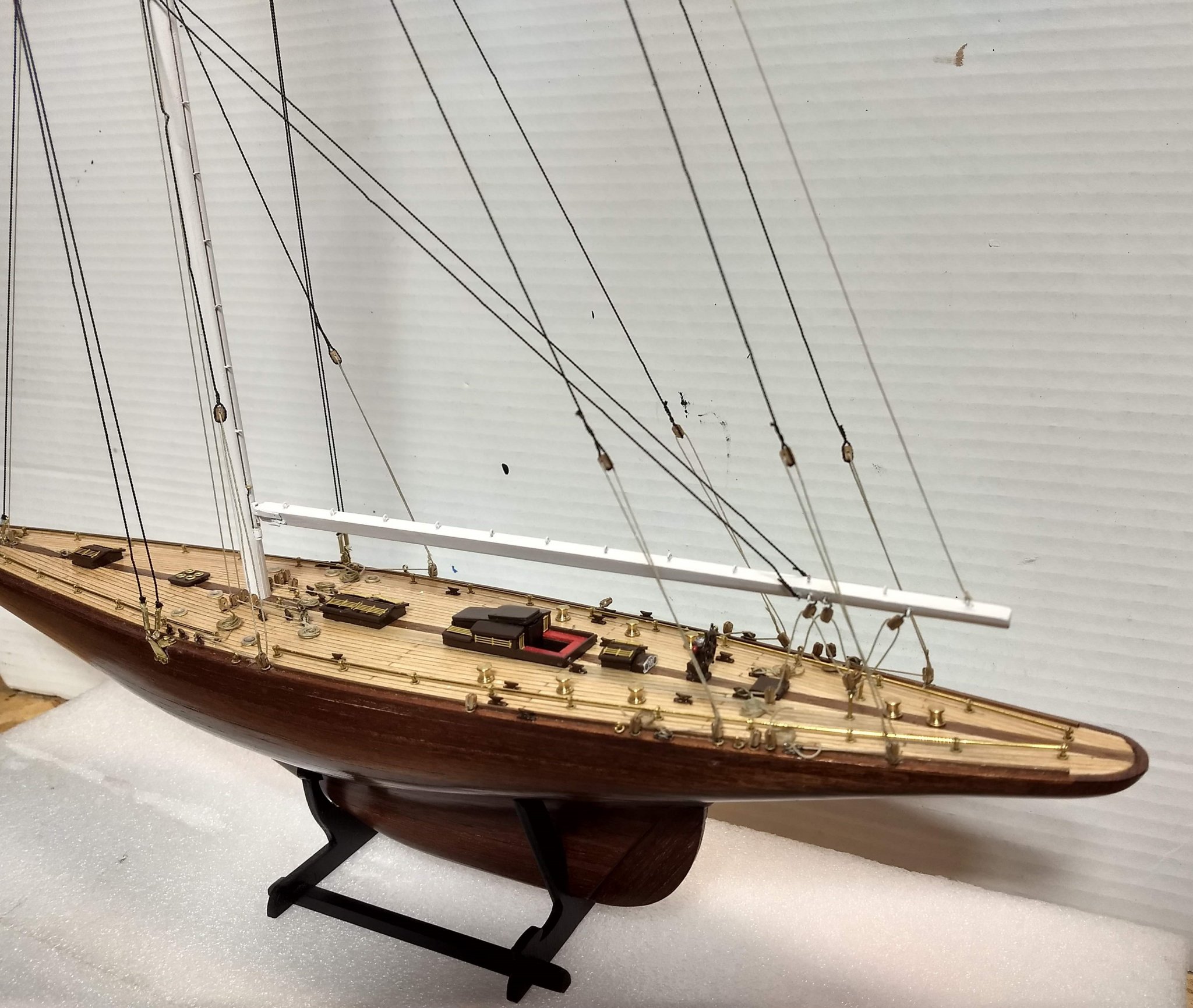
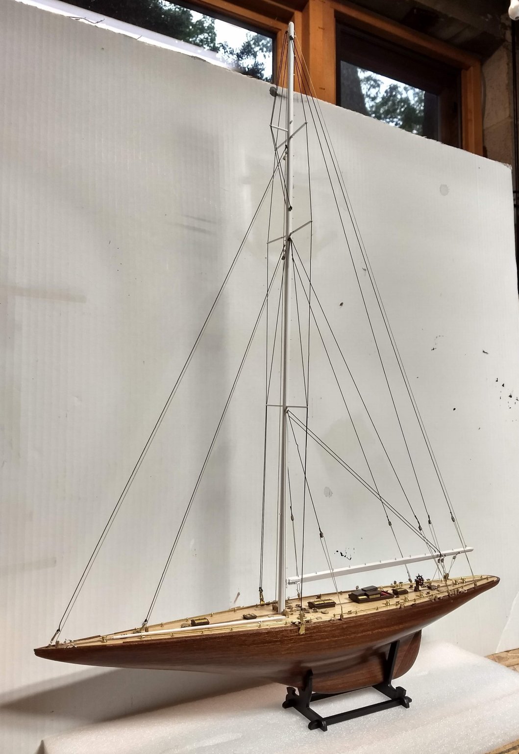
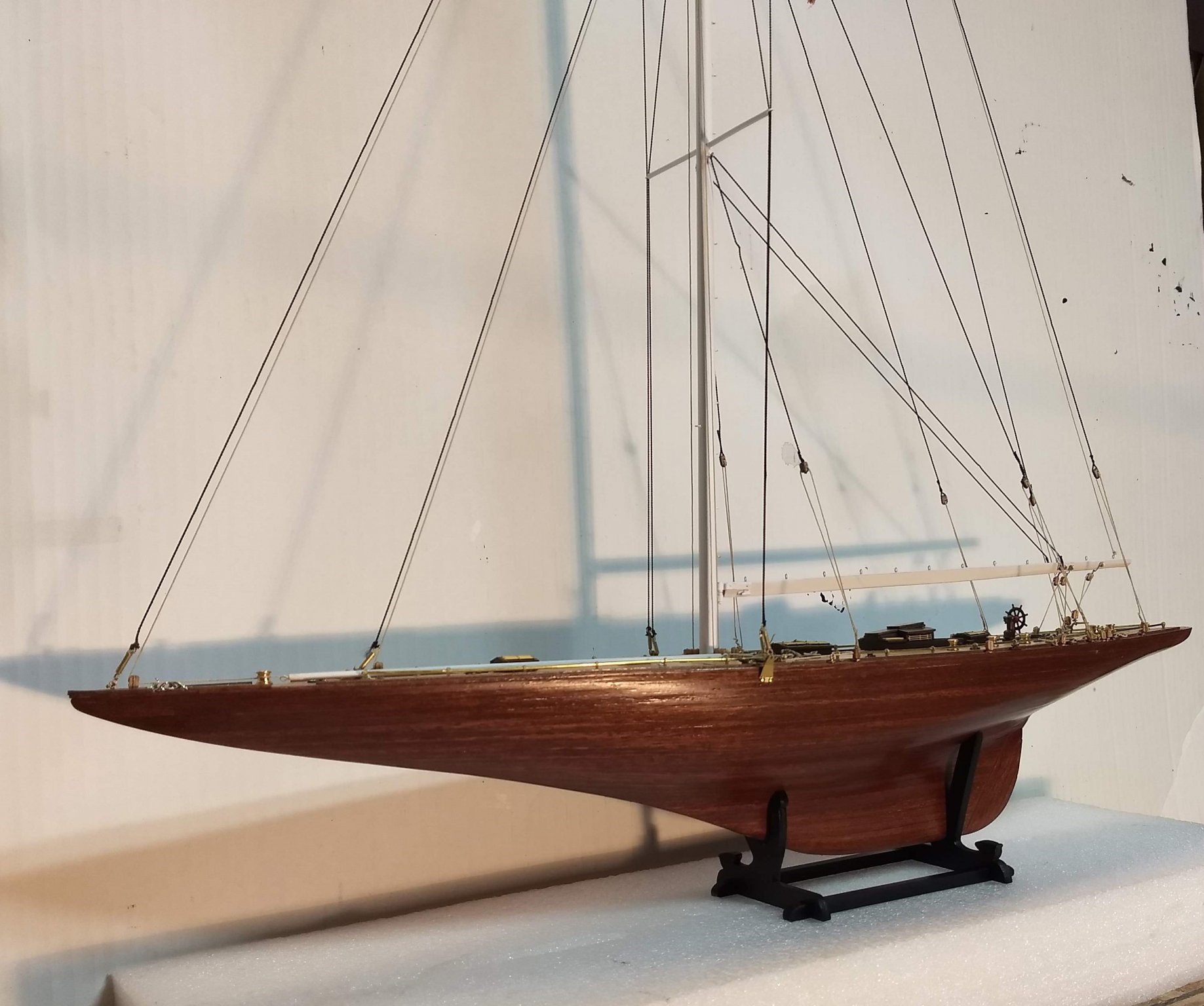
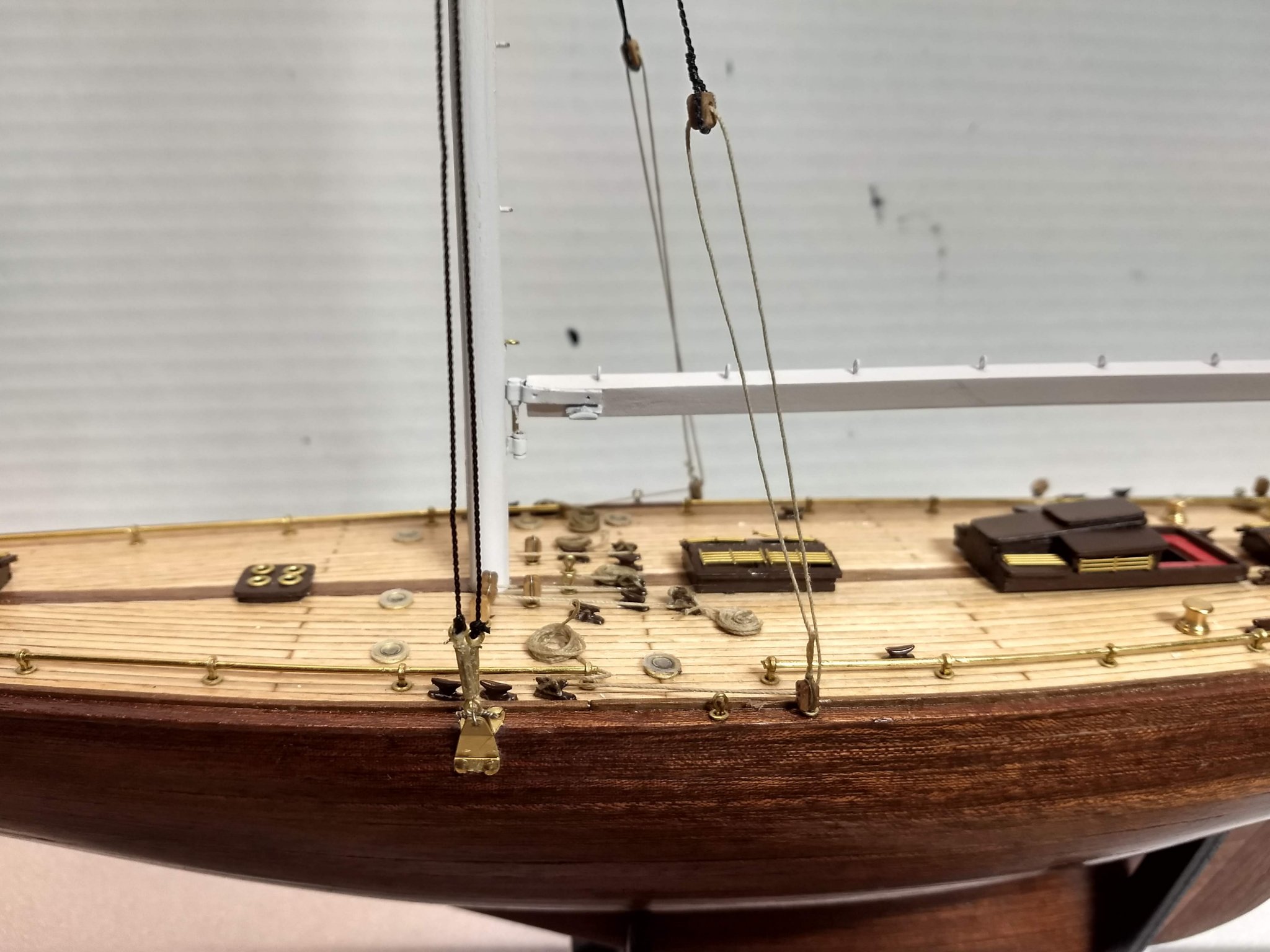
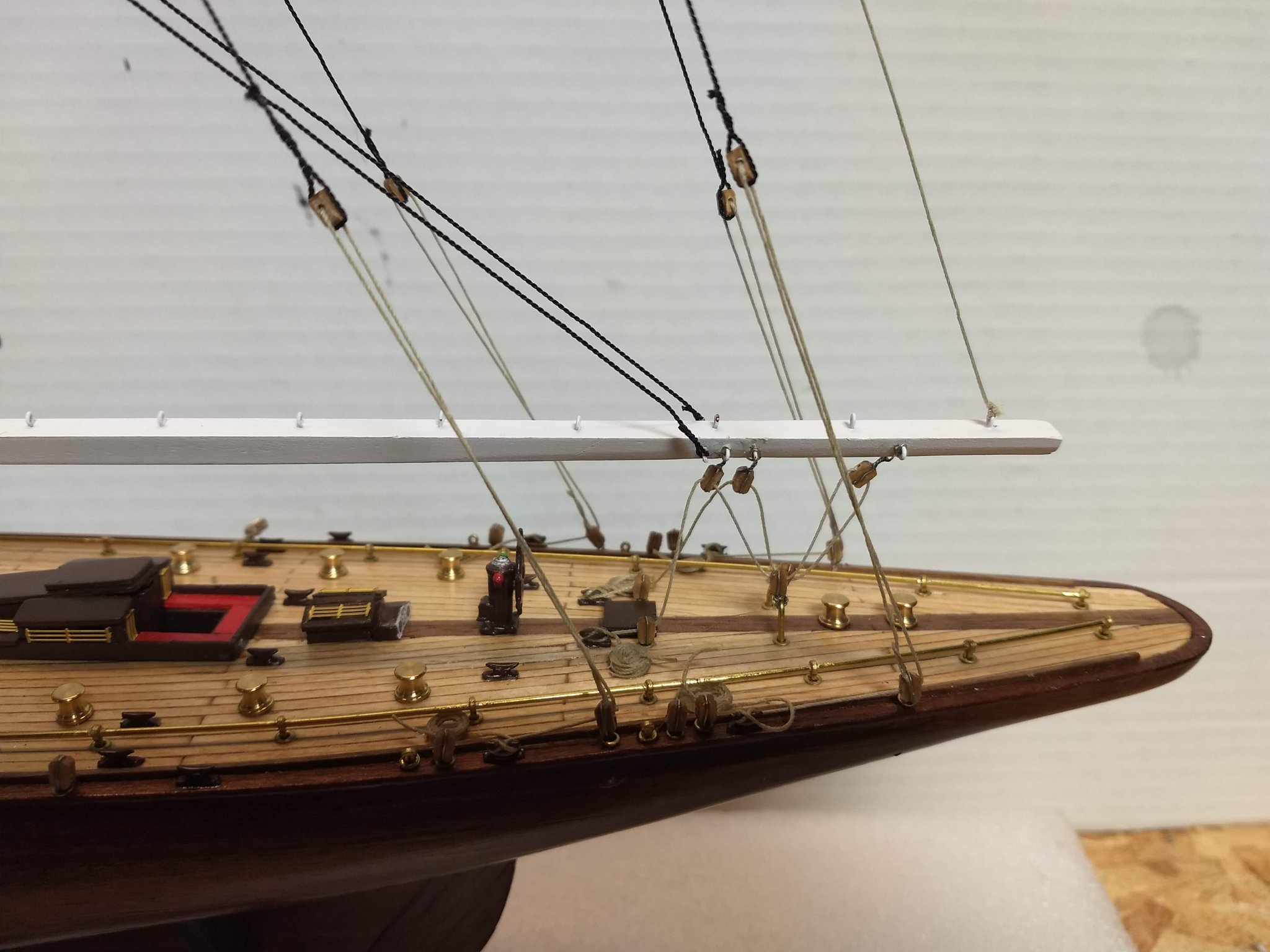
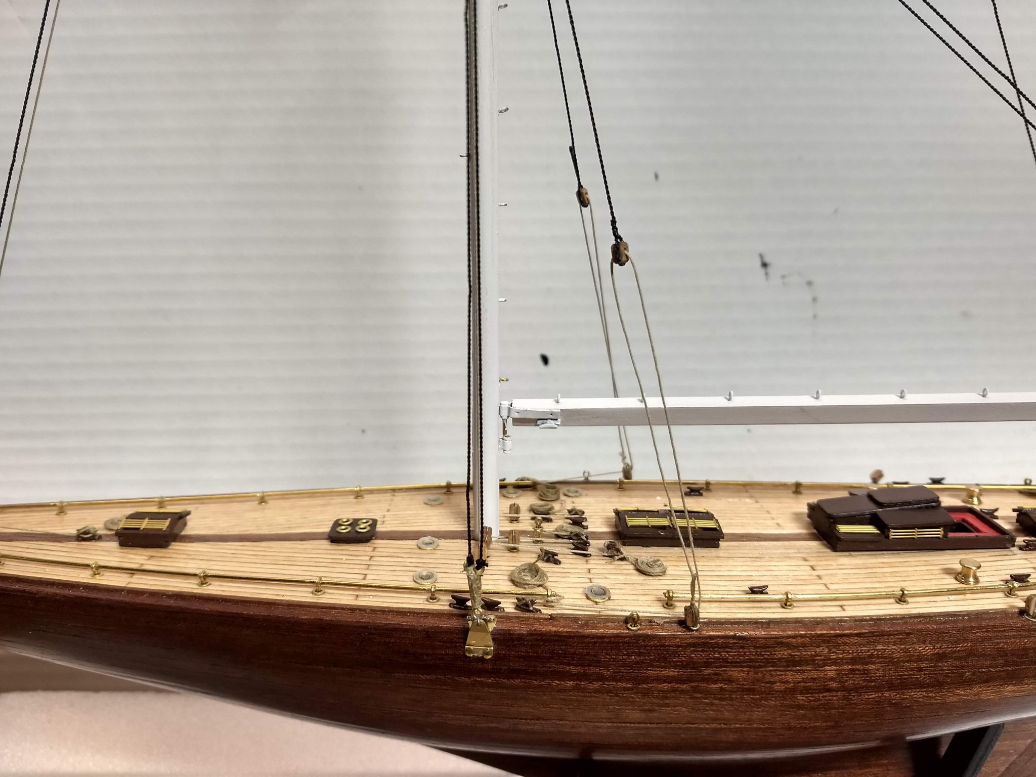
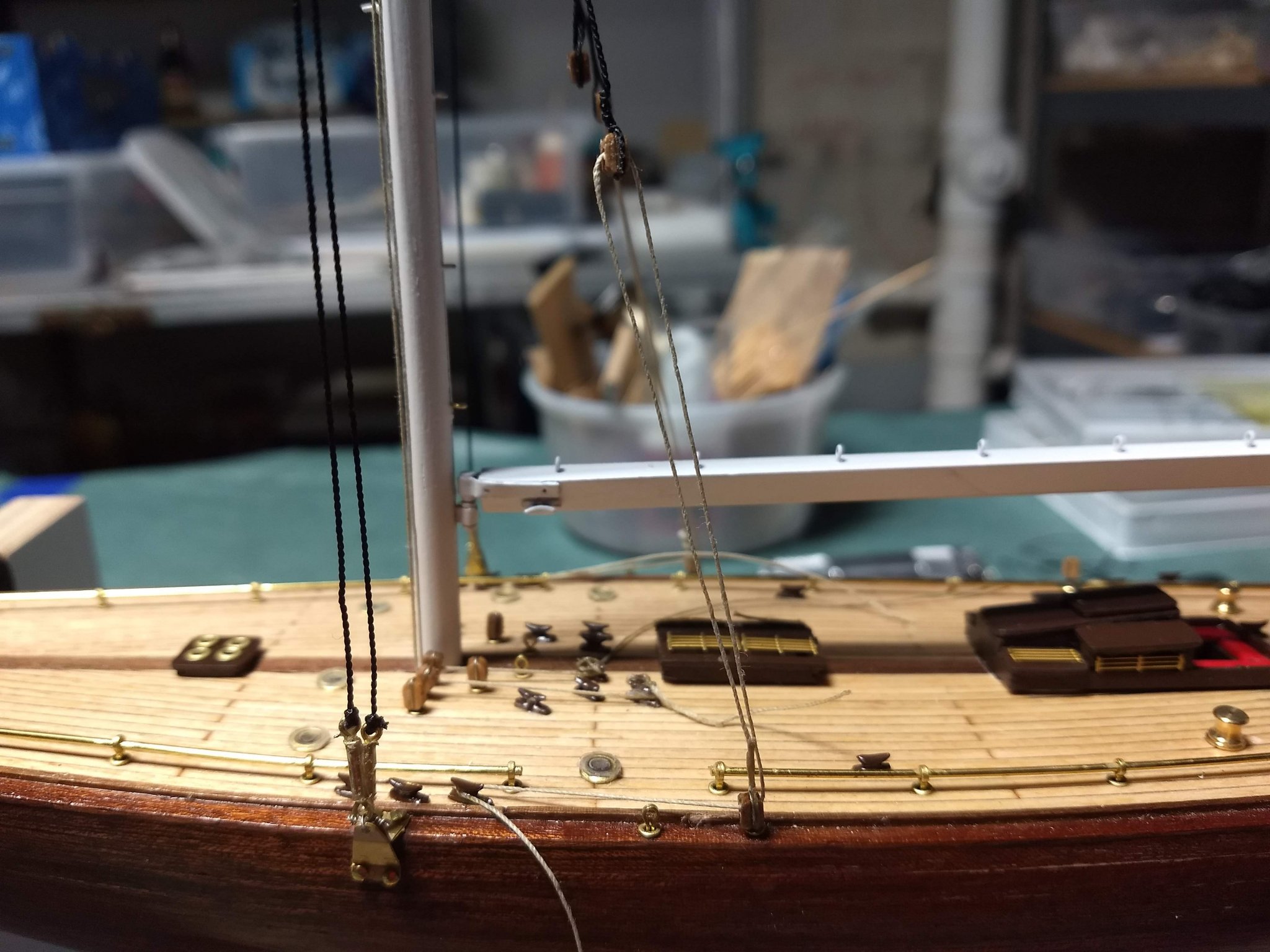
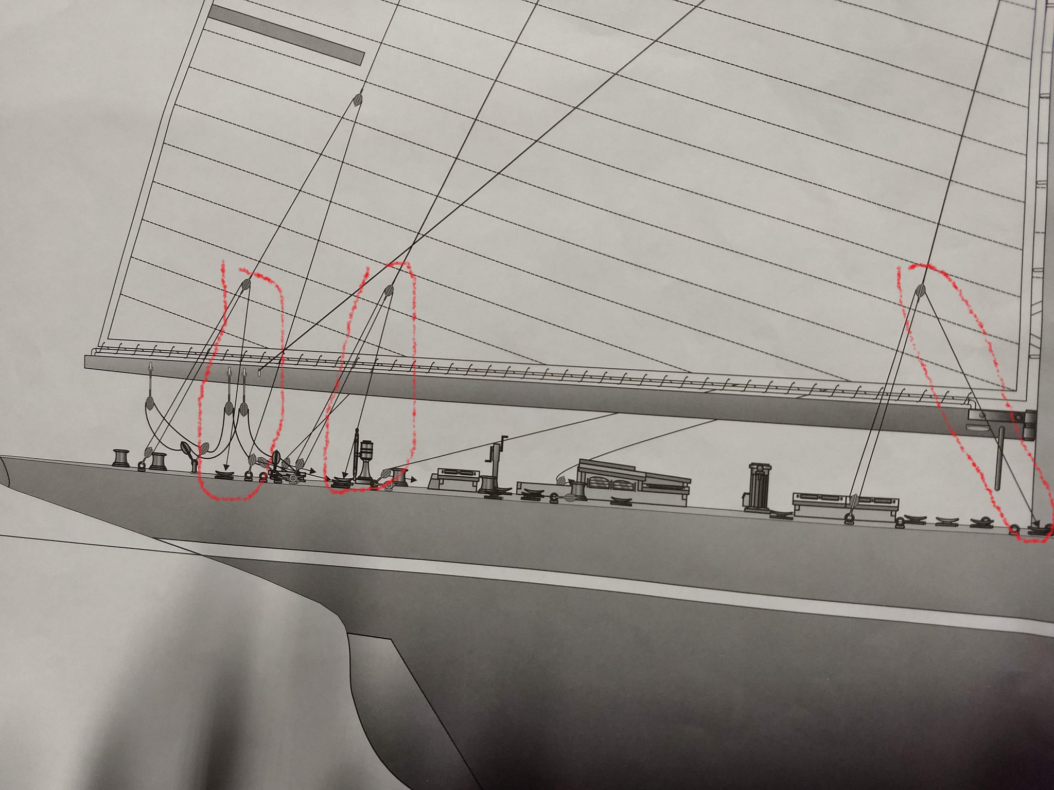
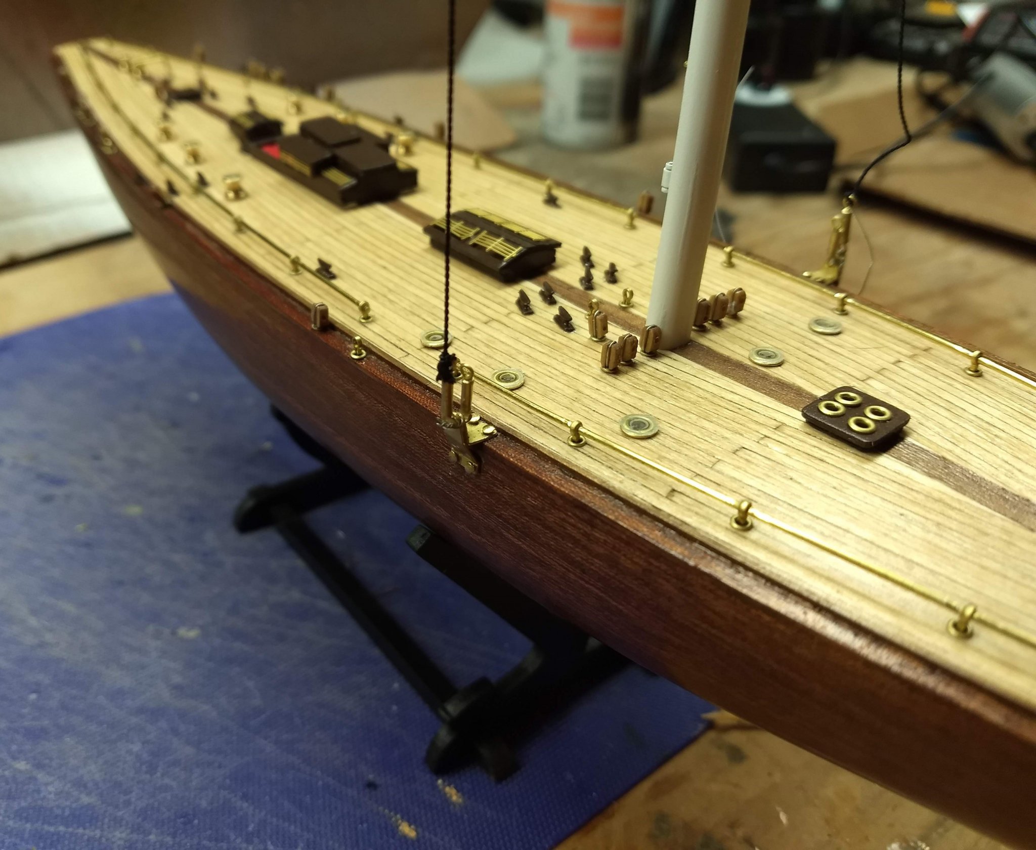
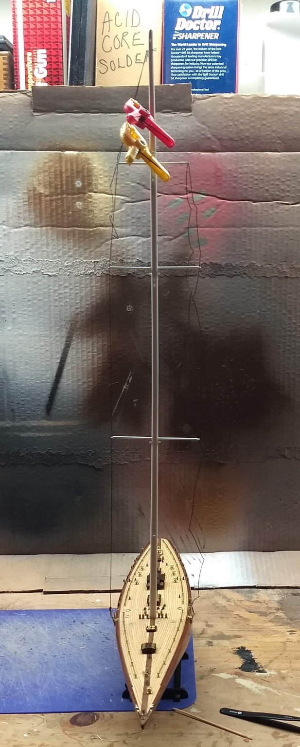
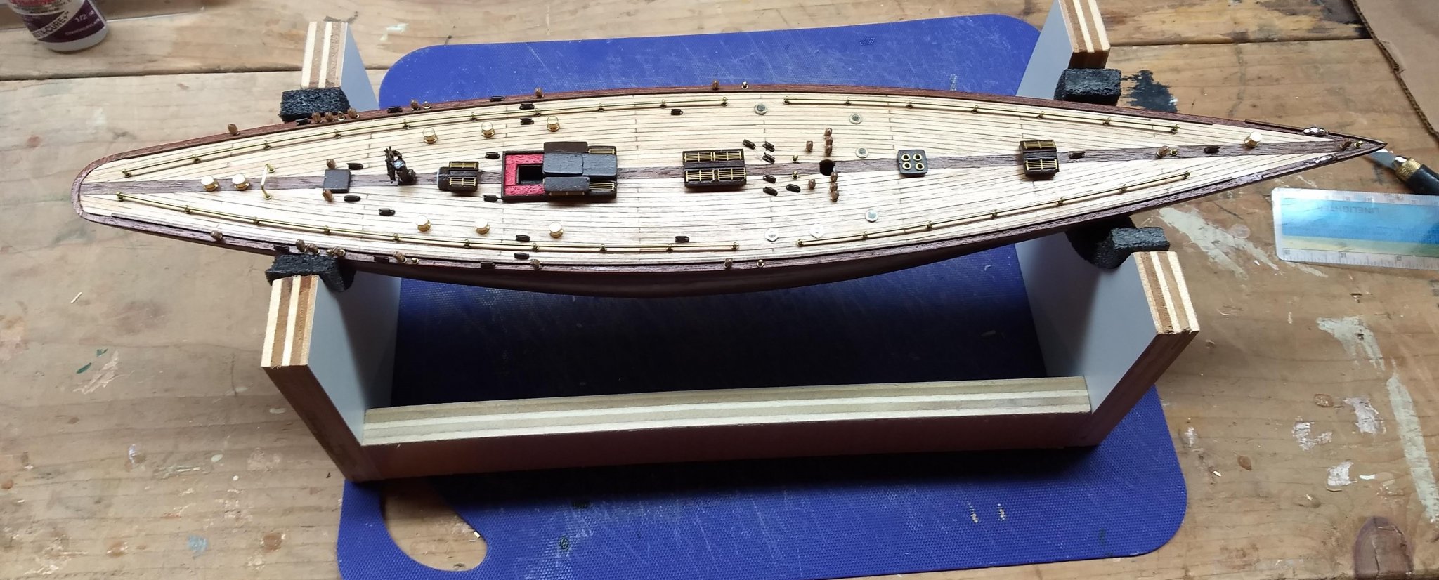
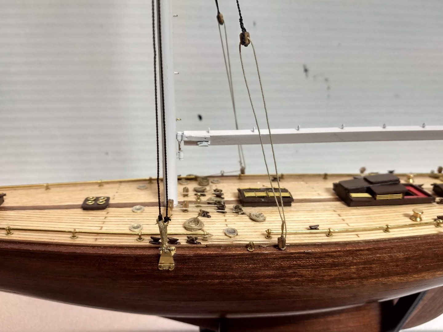
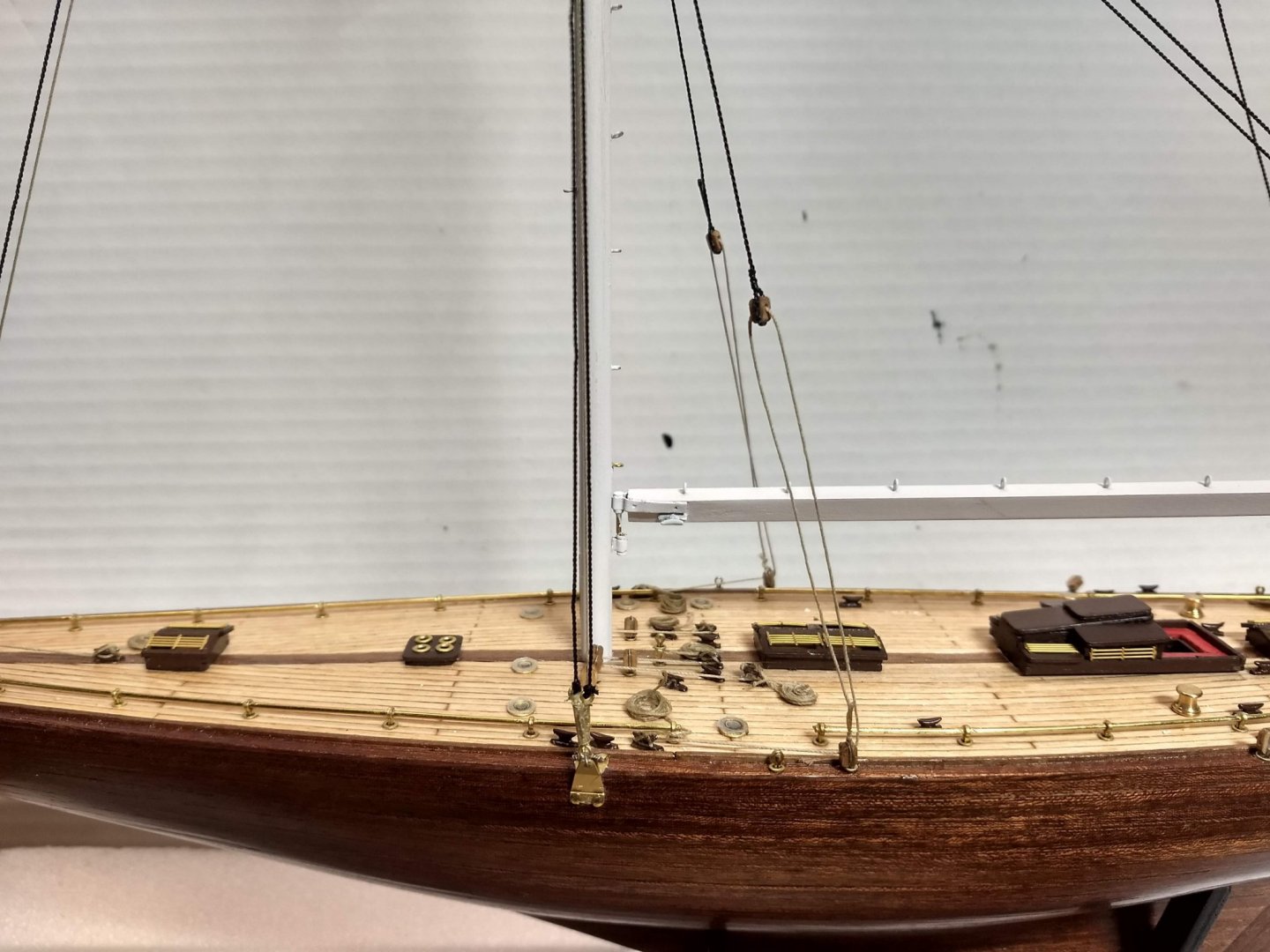
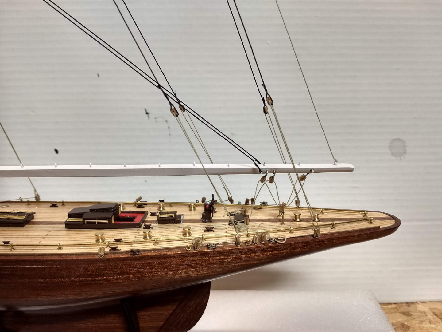
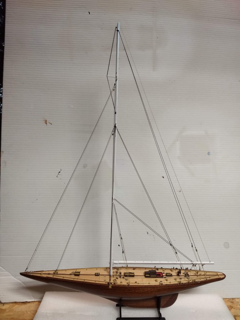
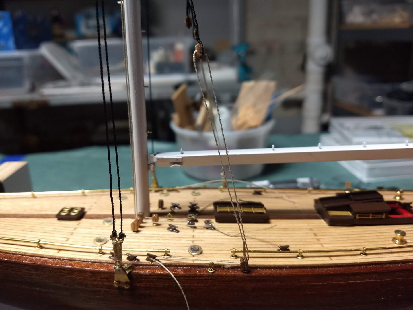
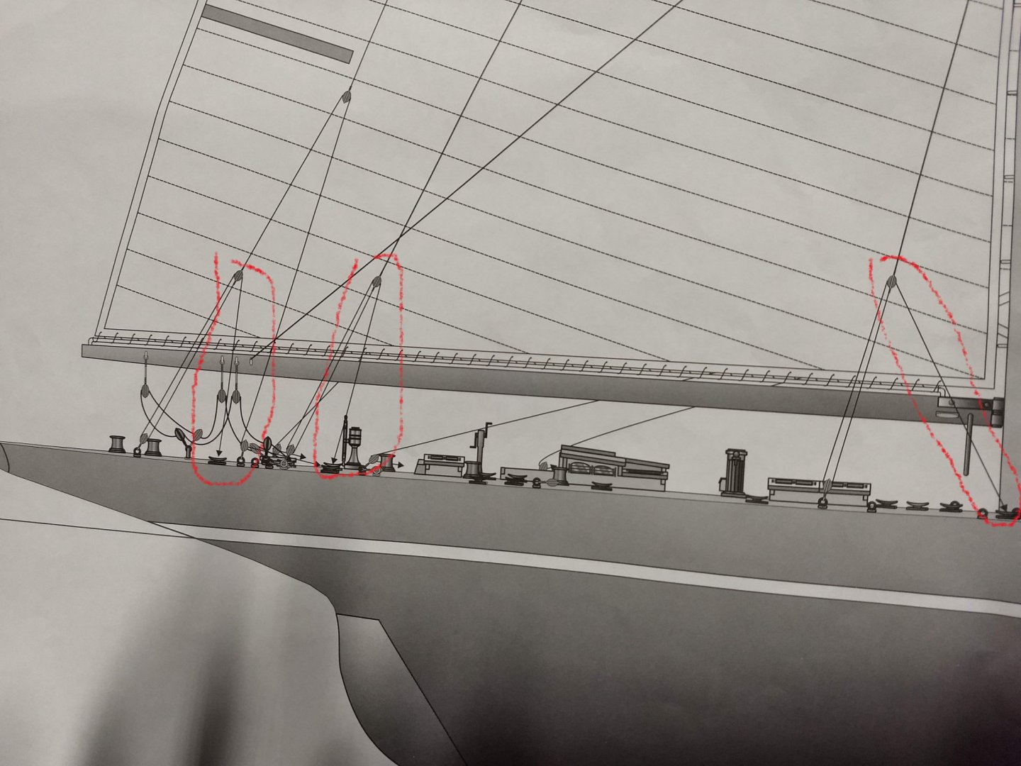
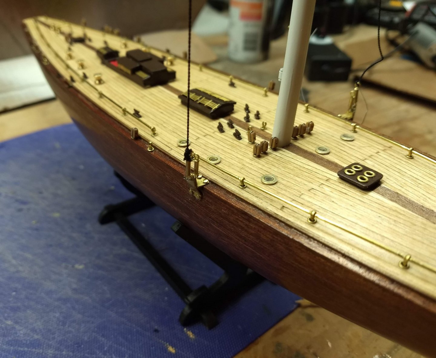
 In the below diagram, it shows the shroud rigging going from the block directly down to a cleat on the deck. That to me seemed a little strange as most boats I have been on lines go parallel on the deck to a cleat. Lines to a cleat do not go directly up to a block. In the diagram, the line goes from the block on the shroud to the deck block, back to the shroud block and then directly down to the cleat on the deck. A little hard to see on the picture below, but I changed the line to go from the deck block up to the shroud block, down to the deck block and then on to a cleat. To me that seemed better... Also of note, I did not put the 2nd block/tackle to the back shroud. For some reason it with the small scale a boat, I felt it would look a little "stringy" if I added the 2nd block/tackle between the 1st and 3rd block/tackle... Not sure that was a good decision, but that is how it ended up. Rather than have line just go to each cleat and then just stop or lay on the deck, I added some coiled rope to each cleat. Especially since I do not plan to add the sails, to me it looks more like a ship at mooring with the lines coiled. At this point I am going to "call it"... This ship is ready for it final home in the case. Below are some final pictures of the completed build and a short video. From here I am moving on the the USN Picket. Kit just arrived the other day and I am anxious to get started on it. Finished_Video_1.mp4


- 45 replies
-
- 3
-

-
- j-class yacht
- amati
- (and 2 more)
-
Julie Mo Thanks for your comments... Prior to my building the 1:80 J Class I looked at your build of the 1:35 J Class boat. You are a true craftsman in every sense of the word. The detail and customization you put into your ship was outstanding. A true masterpiece. I got the feeling you were building a real J Class boat - not just a model. Anyone wanting to build either J Class boat (1:80 or 1:35) has to look at your log. What a beautiful ship. Thanks for sharing your build and the detail you put into your log.
-
Turangi I am somewhat new to modeling and just starting the Picket....I would like to thank you for taking the time to explain the cutwater trimming. The instructions in that area (and a lot of other areas) are about as"clear as mud"... You brought a lot of clarification to the cutwater mystery.
- 54 replies
-
- 1
-
-
- picket boat
- model shipways
- (and 1 more)
-
Jeff5115... Thanks for the comments..... Not sure I intended this to be an instruction manual as I am by far no expert builder, but I did want to point some of my mistakes (pain) I had along the way. Other ship logs I have read over the years only some of the steps that lead to a fantastic final product. They do not show some of the "pain" endured during the build. To me that is not very helpful. I much prefer reading logs where the mistakes are listed and the solutions. I know I learn much more from the folks that make mistakes are are brave enough to expose them. Good luck on your completion of "The King"...
-
Kevin101 I just saw you note from june..... ugh... sorry I never got back to you.... You probably have already chosen your glue, if you want my opinion I use Gorilla Wood glue and CA glue on all my models. There are a lot of folks that would cringe at Gorilla Wood glue as they say it expands when drying. I starting using Gorilla Wood glue with my first model (before I realized what others were saying about it). I have not had a issue with it and on my 3rd bottle. Most modelers seem to prefer Titbond Wood Glue. I suppose my next bottle will have to be Titebond just to see if I can tell the difference. The other glue that comes in very handy is CA glue. There are three types of CA glue (thick, medium, and thin). I use the thick CA on parts that have to stick together relatively fast. All the railings on the King were done with thick CA glue as it would take forever using the slow drying wood glue. I really like the "thick" CA (it is not really that thick) as has a long bottle life and does not seem to dry out. I have fully used every bottle of thick CA glue. Best part about the think CA glue is that it is easy to work with. Thick enough to stick on then end of a toothpick. On rare occasions I have used the thin CA glue. It is much harder to use than the thick (as it runs all over the place), and it tends to dry out. Using thin CA glue you are constantly clogging the glue tip. The one use for the thin CA that I have found is when you have a couple parts that have a very thin seam that you want to bind together. Just pour a drop on the seam, and it will seep into the seams and lock them tight. A few hints on both CA glue and Wood Glue.... use as little as possible. A little goes a long way. If you use too much it smears onto the wood, it seems even if you wipe it off right away, some glue remains on the wood. No problem if you are going to paint the wood, but if you are going to stain the wood, the part of the wood will not stain evenly. In regards to CA glue, if the tip of the glue does get clogged, Acetone nullifies CA glue. Soak the glue tip in some Acetone overnight and in the morning, it will be completely clear. Good as new. Anyway, as I have mentioned earlier in the log I am by no means an expert builder.... So take what I say with a grain of salt.... but I wanted to at least give you my thoughts.
- 42 replies
-
- 1
-
-
- king of the mississippi
- artesania latina
- (and 1 more)
-
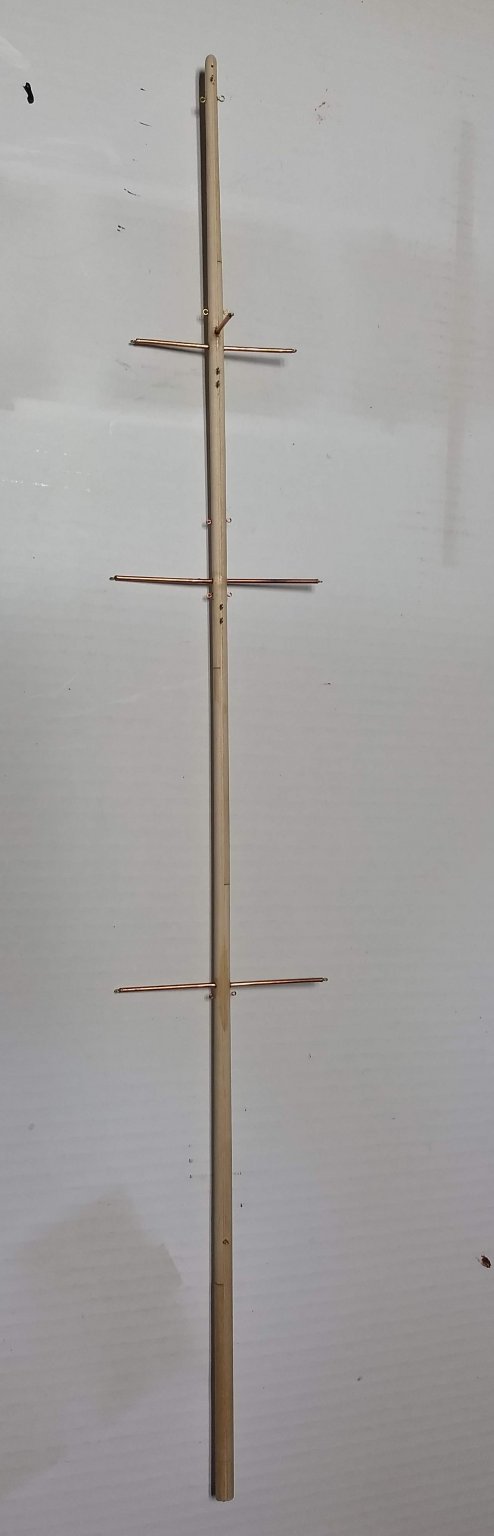
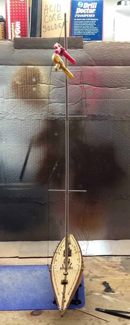
Next up is starting the shrouds. I started on the two main port/starboard shrouds. Attached each shroud to a turnbuckle on each side of the hull. Then strung the shroud up the mast. Below is a shot of the shroud attached to my "makeshift" turnbuckle. At the top of the mast I would temporarily run the shroud through the ring and clamp it. That way the tension on the shroud can be adjusted on each side to make sure the mast is straight. Once happy with the mast angle, put a tab of CA glue on the shroud (at the ring) to hold it. When that dries you can permanently tie it off. Not sure that is how an experienced builder would do it, but with my novice skills, that seemed to work for me. To make stringing the shrouds easier, before stringing each shroud, coat the last inch of the shroud with CA glue. When that dries, it will be stiff and much easier to string through the mast rings. Once tied off, the stiff part of the shroud can be cut off.
- 45 replies
-
- 2
-
-
- j-class yacht
- amati
- (and 2 more)
-
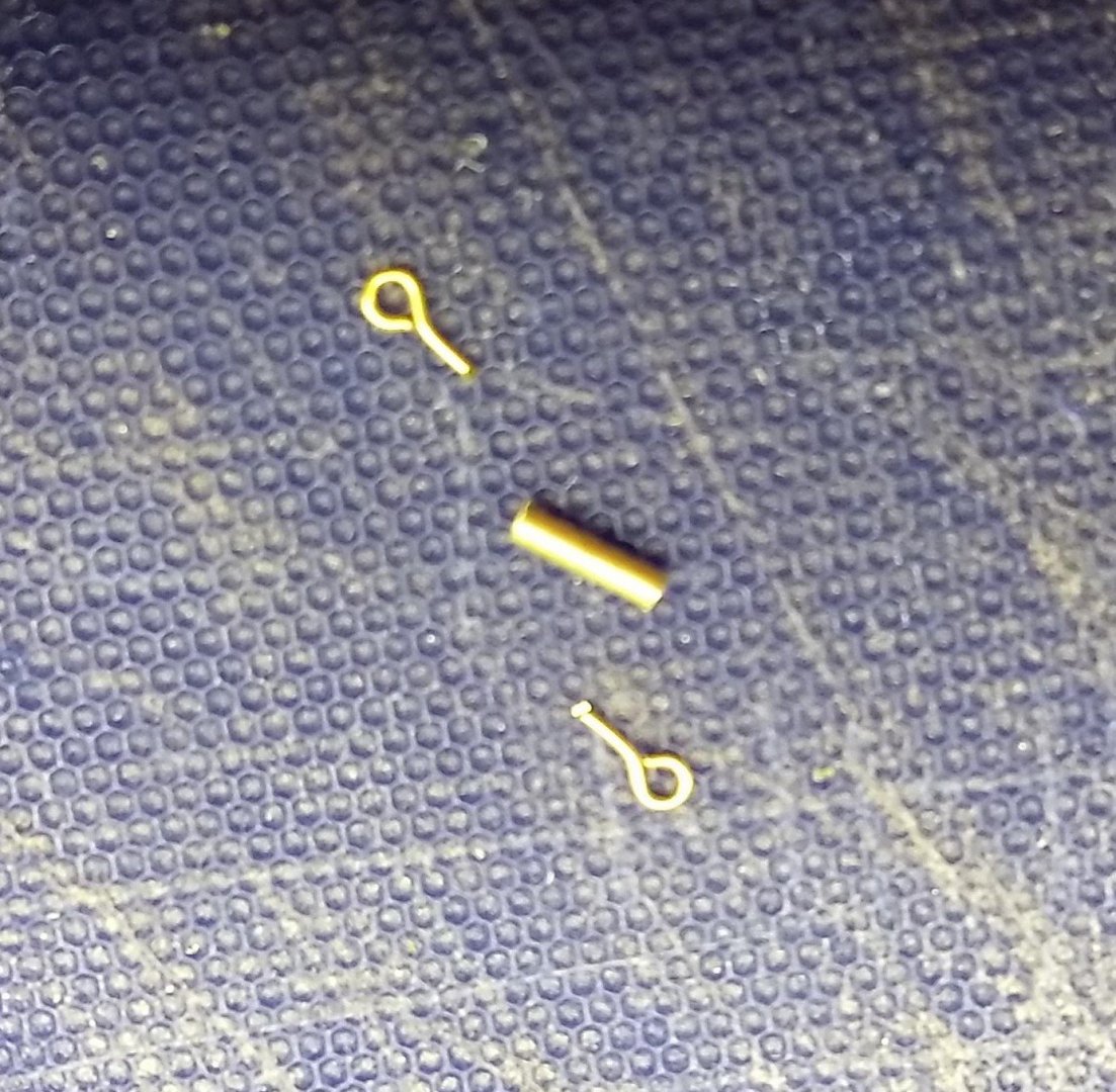
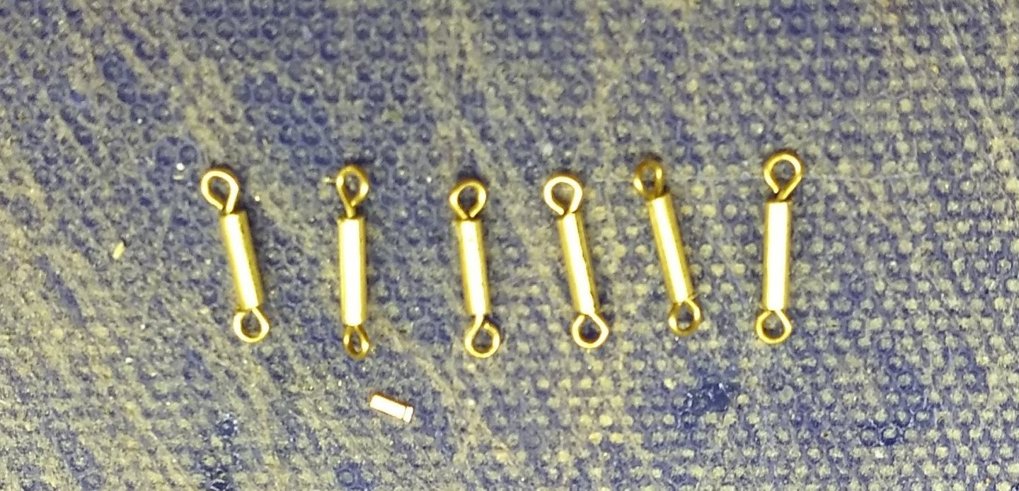
Prior to the rigging I decided the Rigging shrouds really should have turnbuckles. Just tying the shrouds to a ring on the deck did not seem to have the right look. I looked around for some pre-made turnbuckles, but the smallest ones I could find were 15mm - and about $6.00 (us). UGH. 15mm (in 1/80 scale) would be equivalent to about a 5 foot turnbuckle. A little large. I decided to go the cheap route and make what some would call a turnbuckle.... I can at least pretend... Taking some 1/16 inch tubing I cut it about 8mm long (still huge in 1/80 scale), that was the smallest my hands could deal with - and inserted two rings in to each end. I think I will need six turnbuckles to hold he main rigging. Below is the final result. The idea is the makeshift turnbuckles will be attached to the ring in the deck and the shrouds will tie to the turnbuckle. Not a working turnbuckle by any means, but I think the look will be OK on the hull. If not I can always go with just tying the shrouds to the deck as the plan call for. We will see what it looks like when I get to that point.
- 45 replies
-
- 2
-
-
- j-class yacht
- amati
- (and 2 more)
-
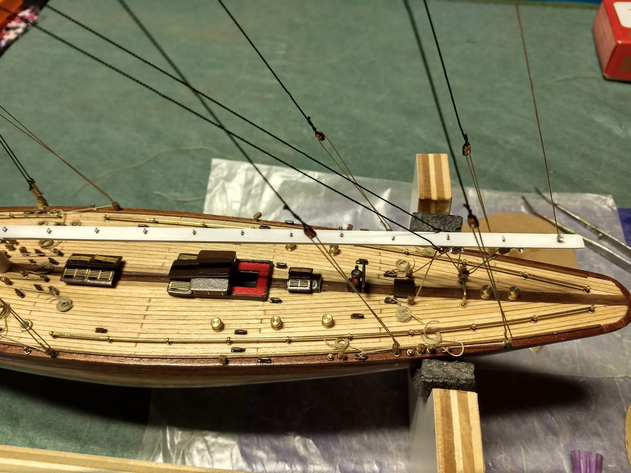
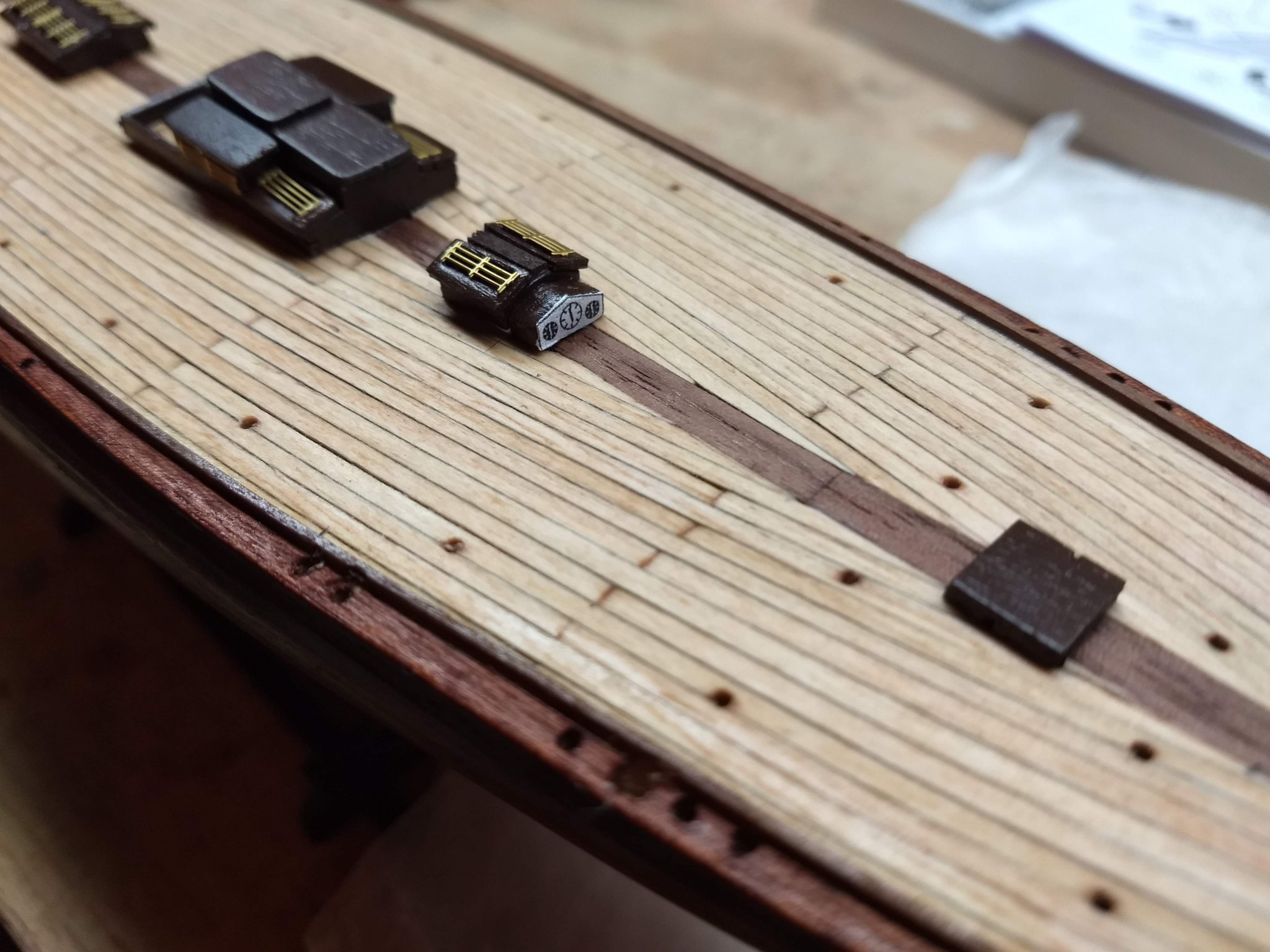
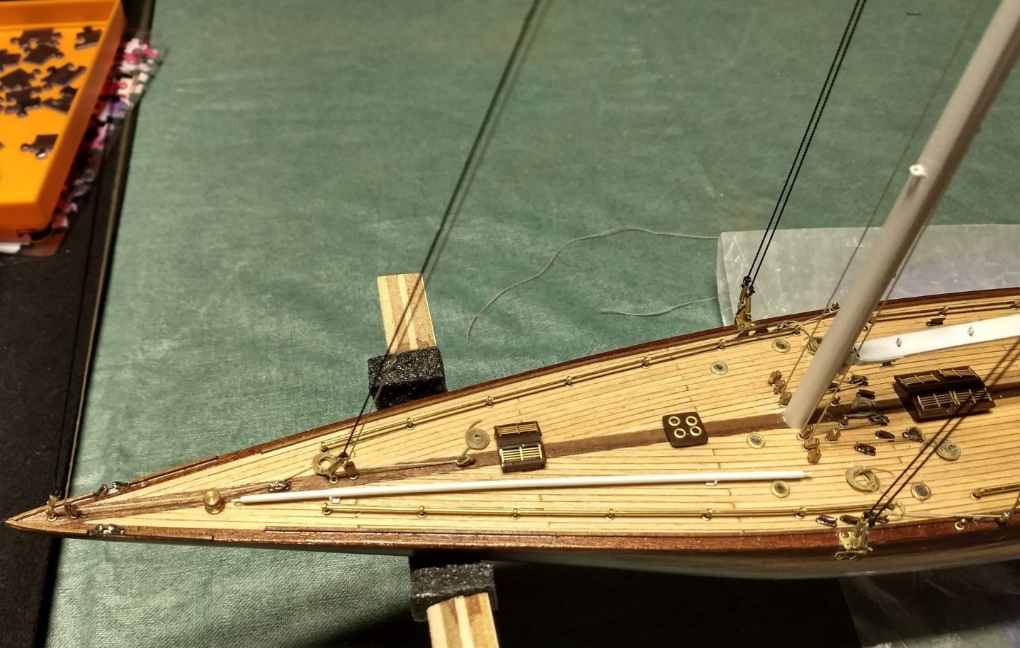
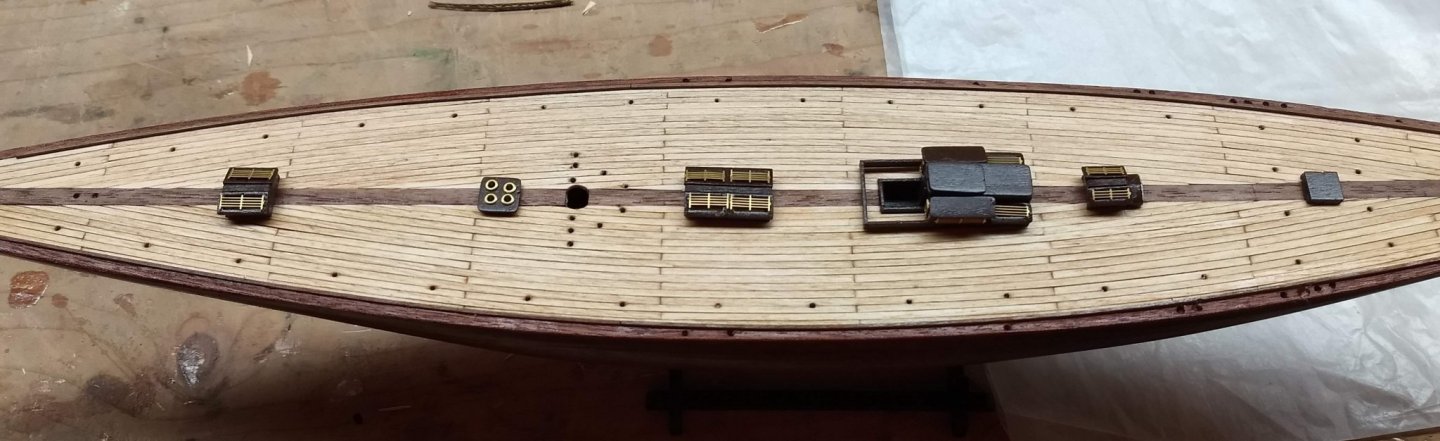
Deck Fittings complete, The blocks inserted directly into the sleeves turns out pretty good. Looks a little more to scale to me. When adding the deck fittings, I strongly suggest putting in the hand rails before you put in the cleats and brass winches. Putting in the winches before the had rails main issue is with the winch at the bow. If that is glued in before the brass forward brass rails, it will be challenging getting the forward brass rail strung. In addition, with the brass rails installed, makes it much easier to locate the brass winches and cleats. Anyway,,, that is my novice opinion on the topic. If you notice, there is no main (coffee grinder) winch or the correct steering wheel post. Either I lost them at this point or they were not included in the kit. In any event, I never really understood in the plans why the binnacle (that includes the compass) was not closer to the steering wheel. To me, In the plans it is located way too far forward to be seen by the skipper. Since I was missing the steering wheel post I used the binnacle (that includes the compass) as the steering wheel post. That way skipper can actually see the compass. Do not have any red or green paint on hand to paint the binnacle steel balls, but I can add those two minor details later on when I have the paint on hand. Tomorrow plan to step the mast and add the rigging....

- 45 replies
-
- 2
-
-
- j-class yacht
- amati
- (and 2 more)
-
Blocks have been inserted into the sleeves. Instructions call to insert an eyelet into the sleeve and then tie the block to the eyelet. I did one that way and did not like the look of it. With the block tied to the eyelet the block seemed to sit too high on the deck. Instead I glued the block into the eyelet. That way the block will sit more or less on the deck and not stick up so high. I do not know if later on this decision will come back to haunt me, but for now anyway, I liked this look better. The hole in the block was re-drilled with a 9mm bit. That seemed to be a good size to where the rigging would easily be inserted.
- 45 replies
-
- 3
-
-
- j-class yacht
- amati
- (and 2 more)
-
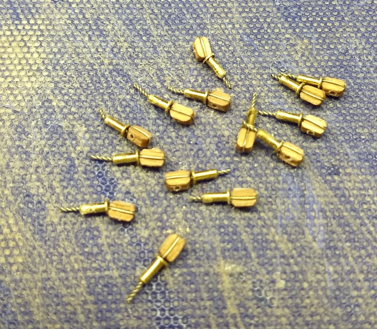
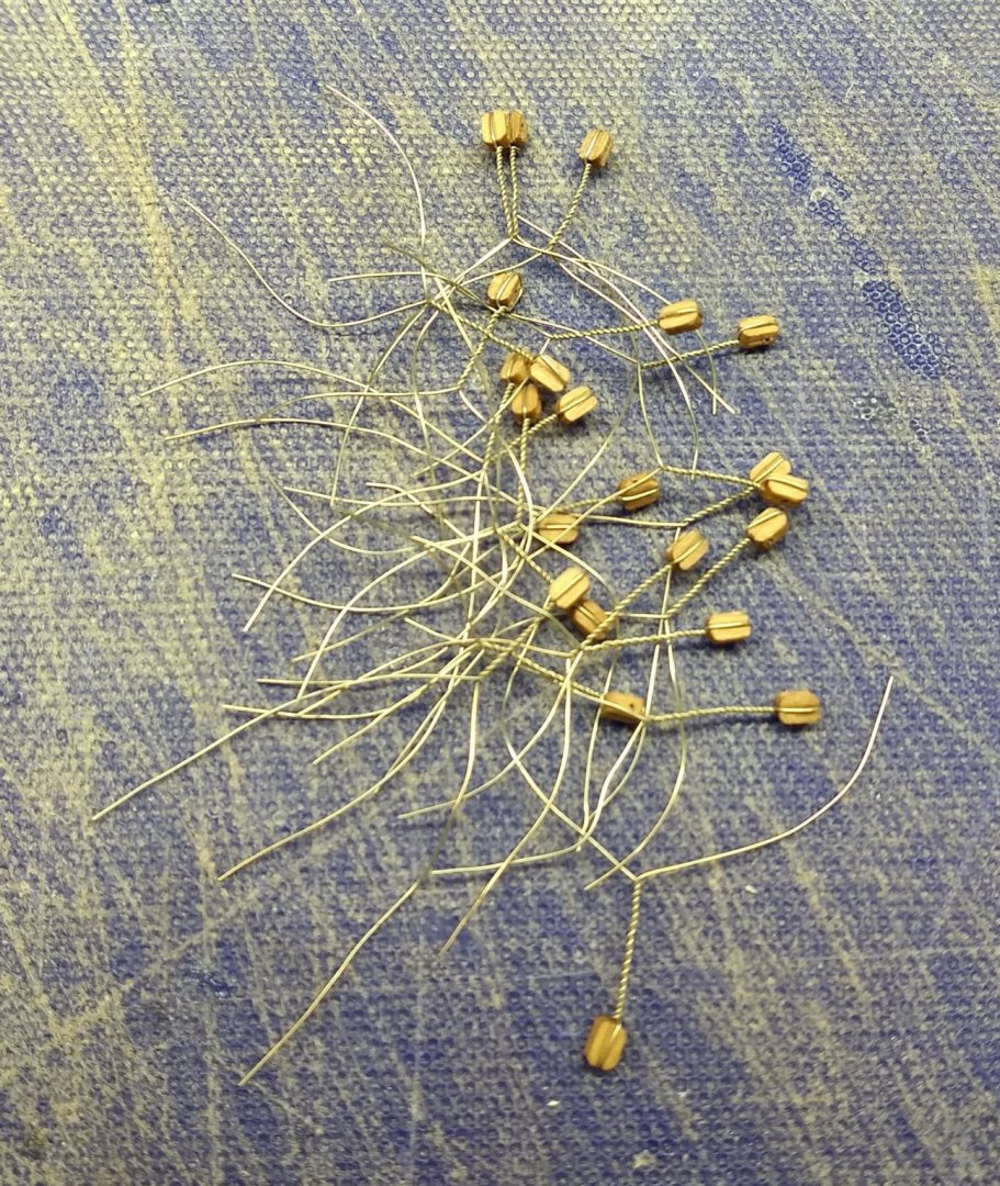
Grand-kids visited us last week and I was tied up all week doing all sorts of grandparent/grand-kid activities. About all I was able to do on the build was to put together the 20 blocks that require a "tail". I decided to use very thin wire to make up the tail. It is much easier to string than with the included tan thread, and I think it might even look better. Basically held the block in a tweezers and the tweezers in a vise. From there just wrap the block and start turning the ends of the wire. After a few blocks the process gets a little old, and after 20 blocks the process gets really old, but in the end they turned out OK. When I get ready insert these into the hull, I will cut them to length. Have not done it yet, but I will probably drill the hole in the block a little larger. Maybe a .8mm drill bit. That will defiantly take all the "sport" out of the rigging process.
- 45 replies
-
- 2
-
-
- j-class yacht
- amati
- (and 2 more)
-
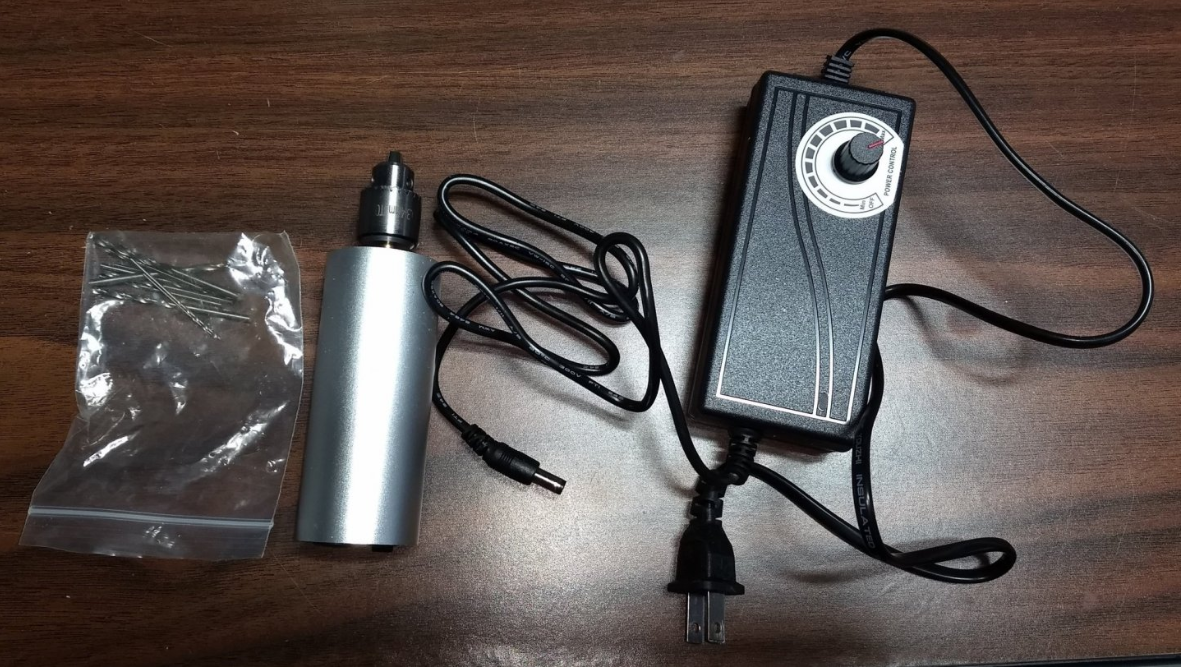
Dave, Actually, I do not have a 2mm drill. My metric drills go from .4mm up to 1.5mm. For the 2mm holes for the skylights I have a bunch of miscellaneous bits that came with the drill I ordered on Ebay. I show it below, but see my long on "King of The Mississippi" for my comments on the drill and extra bits. If you do not have an electric drill, you need to get this one. It holds bits as small as my .4mm bits and much larger bits than you would need for a model. It takes all the (shall we say) "sport" out of drilling accurate holes. I especially like the variable speed control. Anyway, as you can see in the picture, in included was a bag of assorted bits. None of them are labeled, so unless you have a calibrator, there is no way to tell what size they are. I tested a few on a spare piece of wood and found one that drilled a perfect hole for the 2mm skylights. Thanks for your comments on the "2 mm holes for the capstans are not needed". I did realize that and did not drill those holes.... but I do appreciate you comment. Always good to have a 2nd set of eyes. On another topic.... believe it or not I am considering not painting the white water line. I am too that point in the build and either need to make a decision one way or the other. My reason for not painting the white water line comes from the idea that the entire hull is natural wood. In the real boat world that is not normal. A real natural wood boat would have some sort of anti-fouling paint below the waterline. So since is not realistic anyway, I am wondering if a white water line in the middle of the hull (that is natural on both sides of the white water line) would look strange to where the entire hull natural would look better. On the other side of that coin,,,, I wonder if the entire hull (without white water line) would look strange too... I will talk to the "Commodore" (my wife) and get the "correct" answer. 🙂
- 45 replies
-
- 1
-
-
- j-class yacht
- amati
- (and 2 more)
-
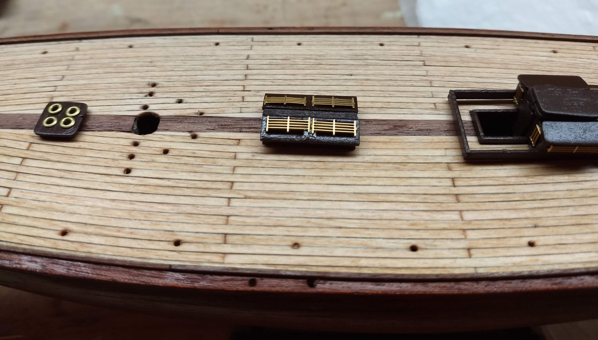
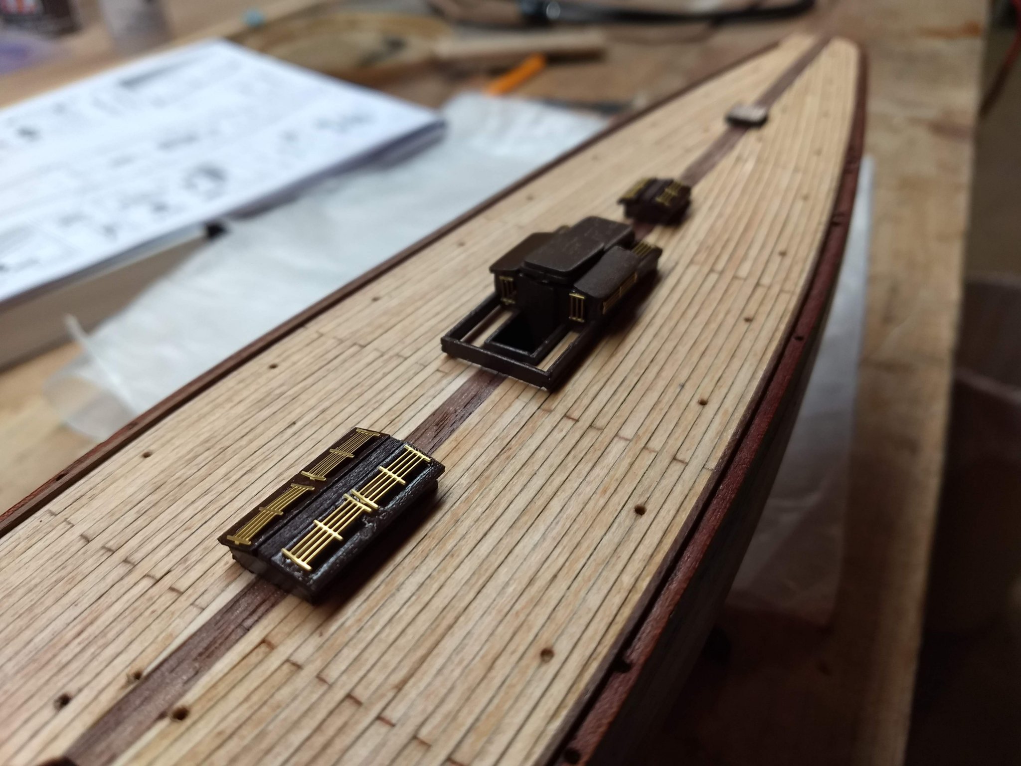
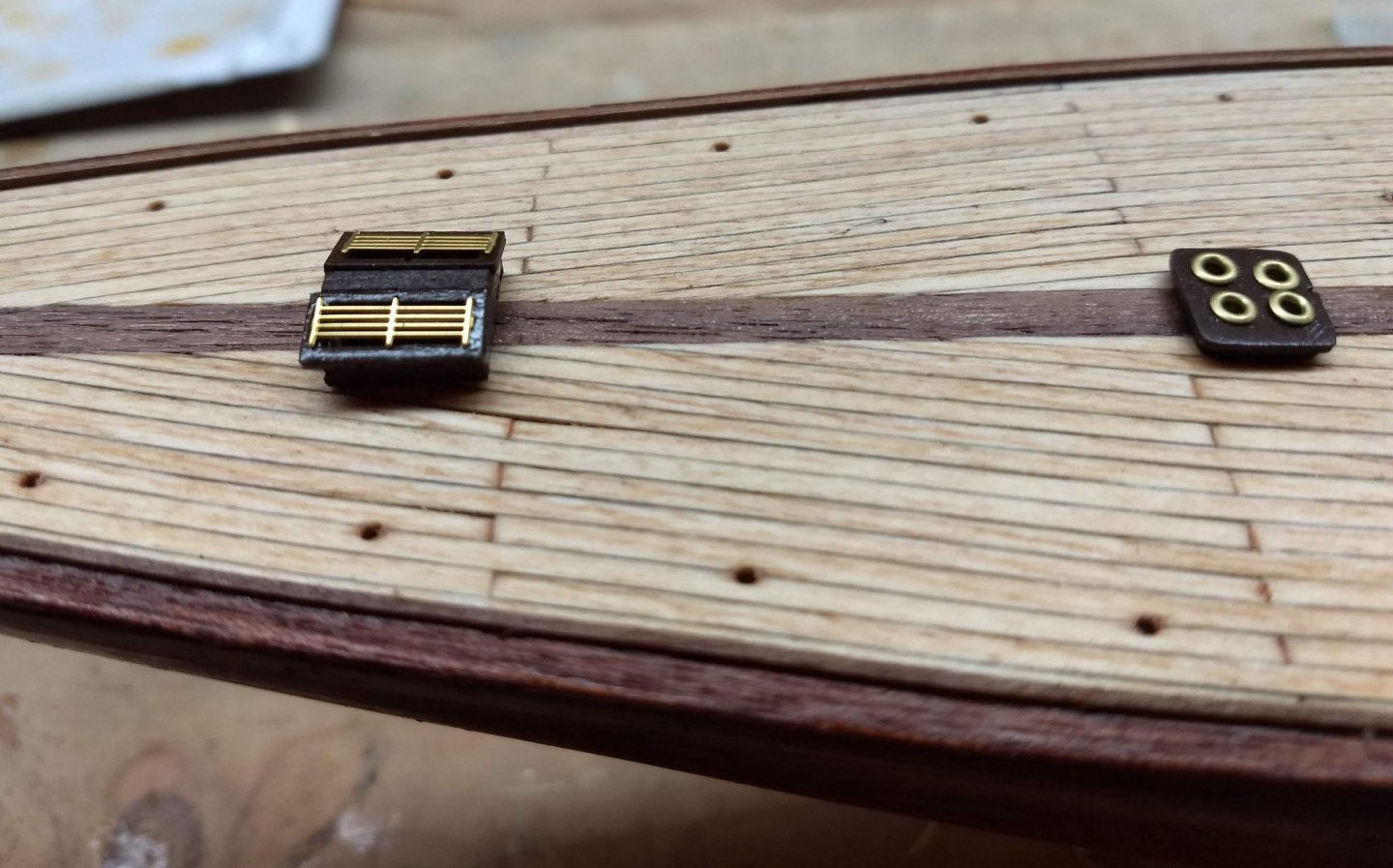
Just completed adding the gold bars the various windows in the deck structures. As Cornhusker1956 pointed out above, it is really hard to add the acetate windows. Not so much as they are very small, but they have to be cut really accurate to only barely overlap the wood frames - Maybe even have to have them be able to be inserted into with windows. Pictures in the manual seem to indicate you just cut them with a somewhat easy overlap in the windows. But as Cornhusker1956 found out, any overlap at all, the windows get in the way of the parts fitting together. See his comments above. Anyway, I just added the gold bars and skipped the acetate windows. Unless you are are very skilled modeler (and I am not) and you can cut the acetate to fit inside the widows, I would save yourself a lot of time and frustration, and skip the acetate windows. I think in the end you will be happier with the result. I know I am. But that is just my opinion. If you are up to the challenge - go for it. Below are the results. The structures at this point are only sitting on the deck and have not been glued. I also have not added to cushions in the cabin entryway. Probably best to do that after I have glued in the cabin structure. Otherwise if they are not exactly in place, the cabin entryway may not lay flush to the deck. If you look close, you can tell the acetate windows are not there, but in the end, no one will notice. I am really glad I did not go through the frustrations of trying to get with windows in those tiny structures.


- 45 replies
-
- 2
-
-
- j-class yacht
- amati
- (and 2 more)
-
David, After giving it some thought, I am going to skip the acetate windows. Since there are the gold bar across all the windows, and because the windows are so small, I am not sure the acetate windows would really show up if they were there or not. Besides, I am sure I would just make a mess of the acetate windows trying to glue them into such tiny spots. The gold bars themselves will he hard enough to make them look neat on the structures. As such I just assembled all the deck structures and painted them a light brown (mahogany like). They look pretty good as they are. Once I have attached the gold bars, I will include a picture. One thing I will say,,,, a big help would be to have two small tweezers to assemble these structures. The parts are really small and big hands just do not do the job. As for the metal grates, I have dealt with them on my last model. You are right, they to have a tendency to fly off to parts unknown when you cut them out. I have lost a few of them in the past. Amazing how they just disappear into the unknown.... John
-
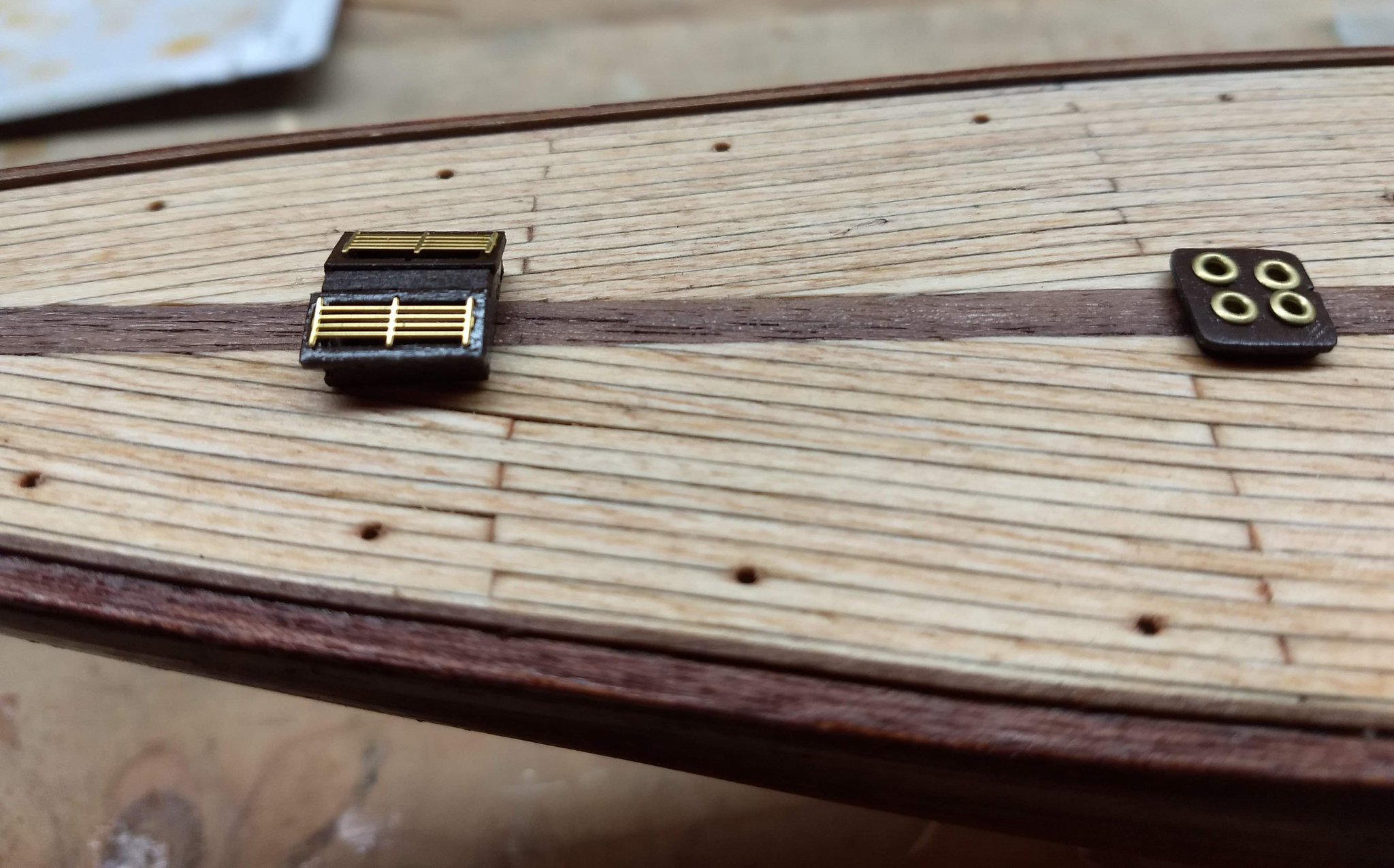
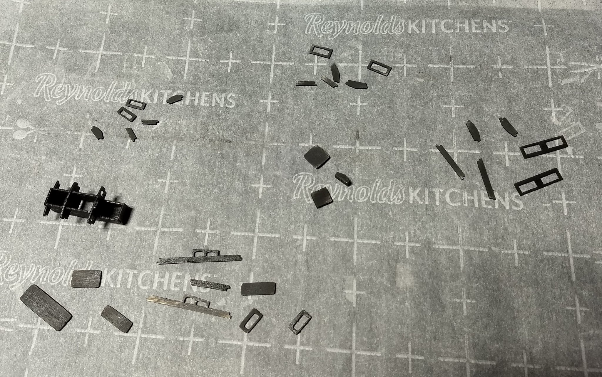
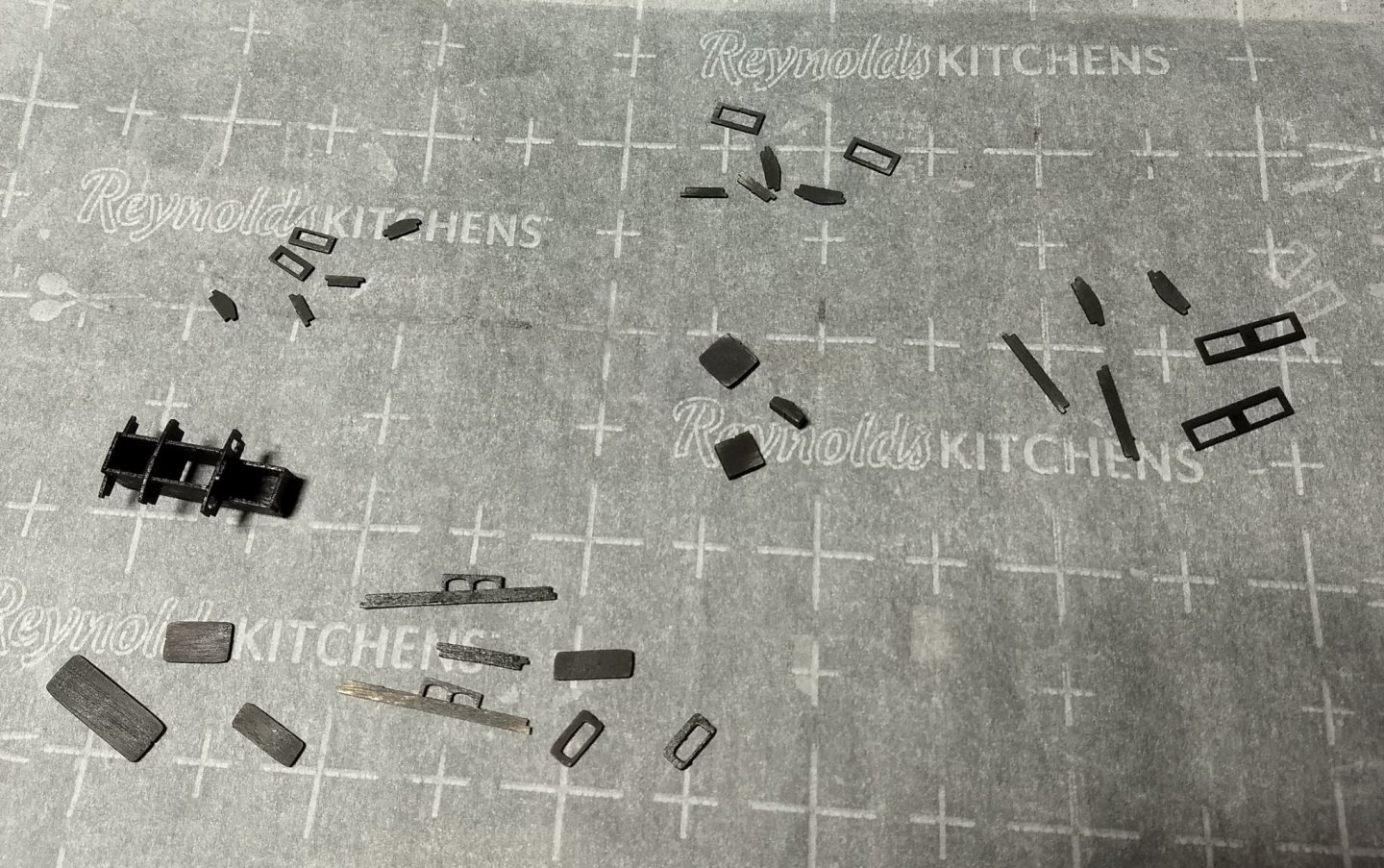
While trying to figure out what stain to use on the deck I decided to look into the deck cabin structures. One note here, the instructions call to stain and assemble each structure. Later on they say to insert the windows. No way you can put the windows in with the cabin structures with them assembled. You need to stain/paint each piece, put in the windows, and then assemble each structure. Below shows the structure pieces after an initial coat of black paint. Instructions called for mahogany paint, but for some reason I felt black would be better. Naturally, after the first coat of black, not sure I like black. So I guess the 2nd coat will be in a brown (mahogany like) color. I am not looking forward to assembling the structures. You can not really tell from the below picture, but these structures are really small. And with my big hands, they are going to be (shall we say) "interesting" to assemble. As for the deck stain, I ended up with Golden Pecan. I wanted a very light stain to more show up the contrast in the wood. The holes have been drilled in the appropriate locations waiting for the eyelets to be inserted next
- 45 replies
-
- 4
-
-
- j-class yacht
- amati
- (and 2 more)
-
David, Take a look at the Amati videoson building the Endeavour. You will find them searching on YouTube under "amati america's cup endeavour". There you will see partx 1 though 19. They show a master building of the Endeavour. Parts 4-10 show the first and second planking. But be sure to look at all 19 videos, they do give some helpful hints. Not sure I follow every thing the say, but they are very helpful as to how someone else has build the Endeavour. They have been and still are very useful to me as I go along
-
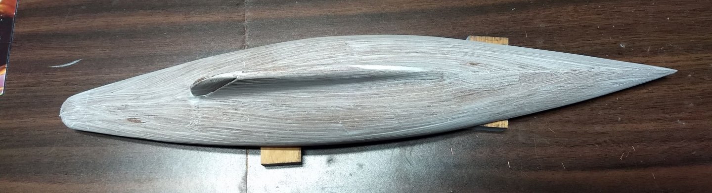
David I had not been to Ages of Sail before, but after you mentioned it I took a look and they have a fantastic selection of wood. In addition they seem to have a good selection of models to build and reasonable prices. I will defiantly give them a second look next time I am in the market for wood or model. As for the second planking, pardon my ignorance, but I am not sure what you mean by "ridge line". Take a peak earlier in my log where I talk about the 2nd planking. I think the main thing that allowed me to get a smooth second planking was the application of the "filla-in-a-bag" I talked about. That was the first time I used it, but I will defiantly use it again. It is a power you mix to the consistency of tooth paste. I covered the entire hull over the first planking. Before it dries you can get it very smooth by just wetting your hands an rubbing over the wet mix on hull. In my case I was so happy with the smoothness of the wet hand rubbing I probably stopped before it was completely smooth. To me it was smooth, but in reality I could have smoothed it more. In any event it sands very easily, but smoothing it more would have saved some sanding. Anyway, after the application of the "filla-in-a-bag", wet smoothing it out, and sanding, the hull was as smooth as glass. Putting on the very thin second planking was very easy. With a little pressure, the thin plans just seemed to blend together. As for the “filler wedges” I too was pretty scared as this was the first hull I have built the required them. My previous build (King of the Mississippi) did not require them, but looking a back I probably should have used one or two “filler wedges” on that one too. As I mentioned in my log, I ended up with way more “filler wedges” than most people, but I just could not get the planks to lay down without them. But with the smooth hull, the second planking seams really blending well together. You have to look really close to see any seams at all. One thing I will say about “filler wedges” (from my initial experience after having done way too many of them) is that they look much harder than they are. They do take patience and very delicate sanding on a sanding block. One thing I did was to only put a “filler wedge" on one end of the plank. The other end was usually cut off at the end of the boat. There is no way I could have successfully put a “filler wedge" on both ends of a plank. As for the painting the brass on the boom and mast, I too was at a quandary as to "paint or no paint". I have been around sail boats most my life and I have never see painted fitting on a mask or boom. But I am new to this modeling, and looking at what most folks have done - they painted them. So I followed like a herd of sheep and painted them. Since then I have see other J Class builds that did not paint them and they look great. If you are on the fence as to "paint or no paint", I would suggest do not paint them, as I kind of wish I had not painted them, but you make the call. Same issue with the cleats on the hull.... I have not gotten to that point in the build, yet but I know it is coming... Again, when was the last time you have seen a painted cleat on a boat. Most boats I know have shiny stainless steal cleats. Not sure what to do with the cleats... same issue .... "paint or no paint" - ugh
- 45 replies
-
- 1
-
-
- j-class yacht
- amati
- (and 2 more)
-
David I really like what you did with the full length planks. They look great. The wood you have used on the middle strip and along the sides - is that stained mahogany or some other wood? Maybe it is just the photos, but it looks darker than the mahogany supplied.
- 45 replies
-
- 1
-
-
- j-class yacht
- amati
- (and 2 more)
-
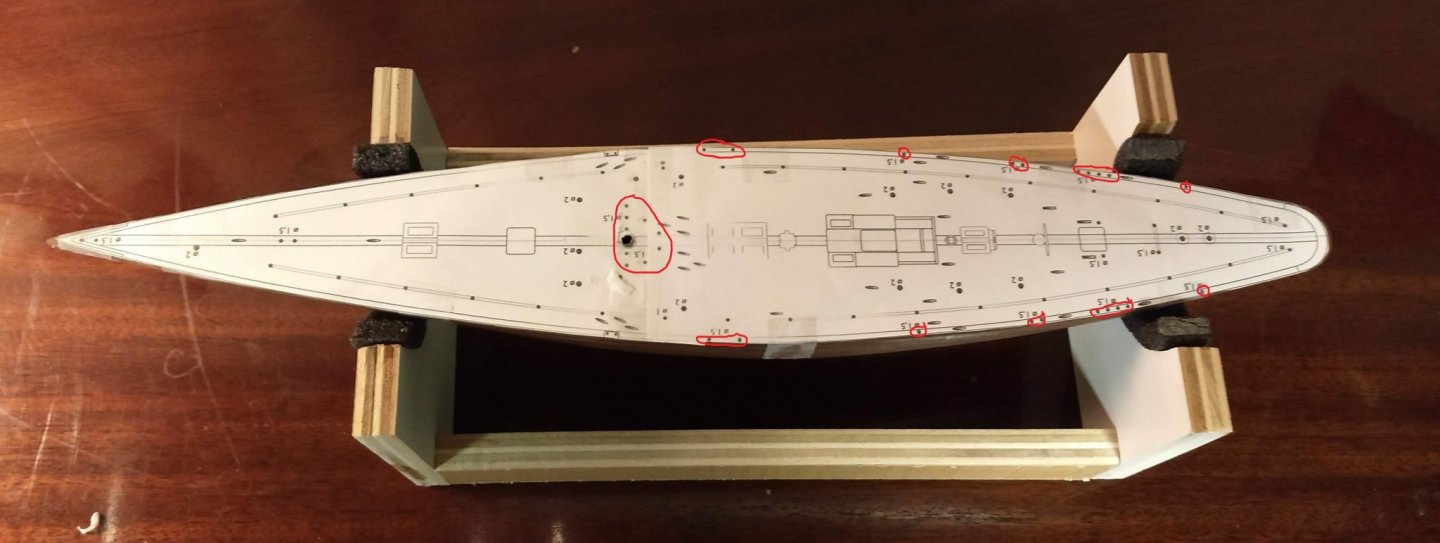
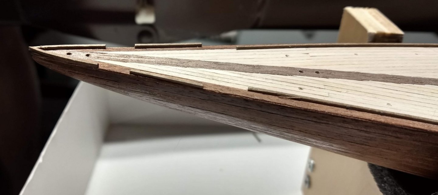
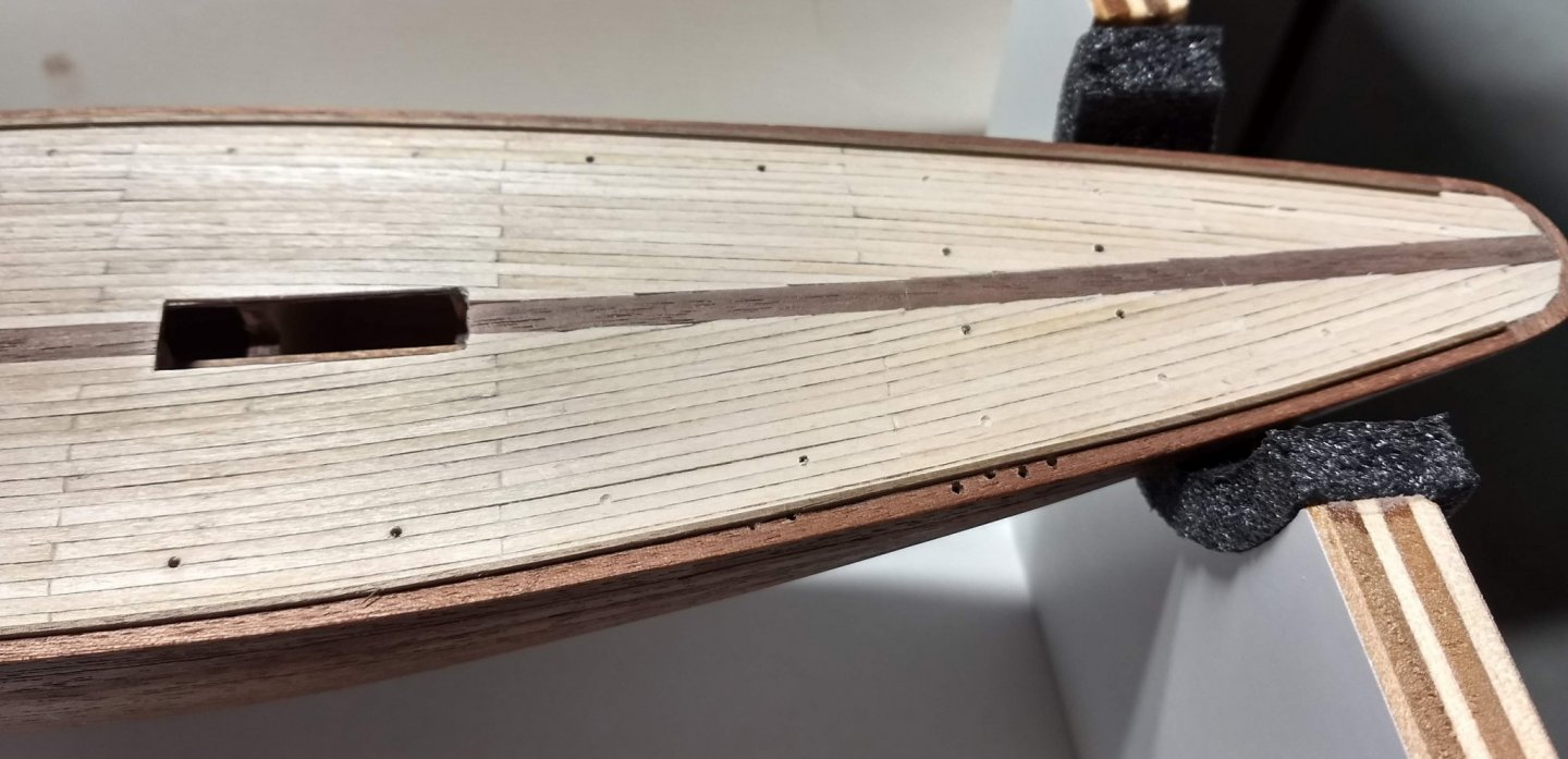
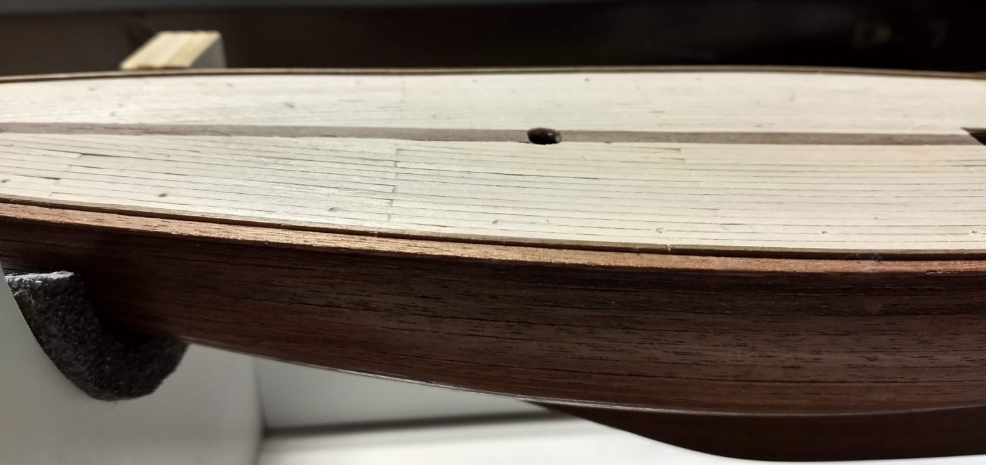
On to the deck holes for the various fittings. One could cut out the deck layout from the plans, but if you want to save the plans, it is best to make a copy of them to cut out. In my copier I had to copy each half of the boat, cut them out, tape them together, and then tape them to the hull. This is good for most of the 1.5mm holes, but not so good for the ones marked in red below. Problem with the "red" ones are that they are either too close to the edge of the hull or too close to the center line. Any variation between the paper copy and the actual hull (and there will be) will not look good when the paper is removed. For the holes on the edge, temporarily lift up the paper and mark the spot with a pencil. Later when the paper is removed you can drill those holes. As for the 1.5mm holes around the mast, you can more or less mark them with a ruler off the mast and drill them. The exact location of these holes is not as important as getting them to line up with the edge of the boat or mast. All the other 1.5mm holes can be drilled off the paper template without issue. Having said that, in the spirit of "do as I say and not as I do", I would not recommend drilling these edge holes at this time. For some reason later on in the build the instructions call to install tow rails on both sides of the hull. To me these toe rails should be installed now - before you drill the deck holes. I drilled the holes before the toe rails, and as you can see below, I have some patching and re-drilling in my future. I suppose if you are very careful with your hole locations you can drill the holes before the toe rail, but I wish I had not.
- 45 replies
-
- 5
-
-
- j-class yacht
- amati
- (and 2 more)
-
Jeff5115, Glad to have you follow along,,,, Remember,,,, "do as I say and not as I do",,,,, and you will have fewer (shall we say) "customization's" and a great finished product. 🙂 Just completed the deck planking. Turned out pretty good, I still think I should have made the planks longer, but I am happy with end end result. Now for the scary part, staining the deck planking. Will be testing out several variations of stain and hope one "calls my name"

- 45 replies
-
- 3
-
-
- j-class yacht
- amati
- (and 2 more)
-
Second planking is 1/2 done... As I mentioned earlier, after intensive study on the best pattern for the 2nd planking,,,,, I probably choose the worst option. I think a better option would have been 20mm planks in a completely staggers pattern. Or maybe 20mm planks staggered every other row. In any event, my 10mm planks will be OK in the end. Next model will try something different. In the interest of "do as I say and not as I do".... below show the 1st half (and a little of the 2nd half) of the 2nd planking complete.
- 45 replies
-
- 4
-
-
- j-class yacht
- amati
- (and 2 more)
-
Turangi I too am very impressed with your work. I am particularly impressed with the time you took to really document your build - Excellent log. It really helps novices like me just getting into ship building. I am currently working on the Endeavour J class boat, but I have the Picket sitting on the shelf as "next up". My work will pale compared to yours, but it will be a far better build than it would have been had I not seen your log. Thanks
-
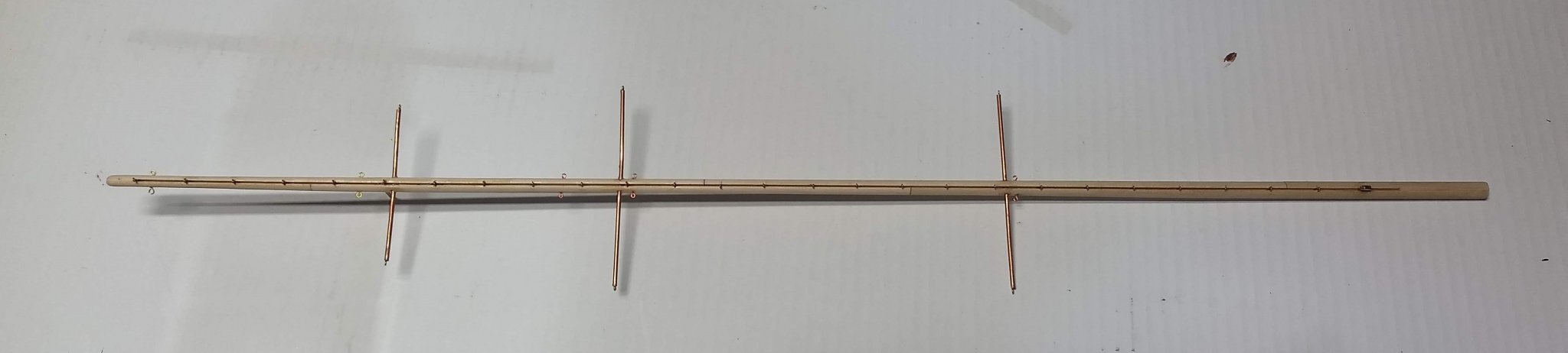
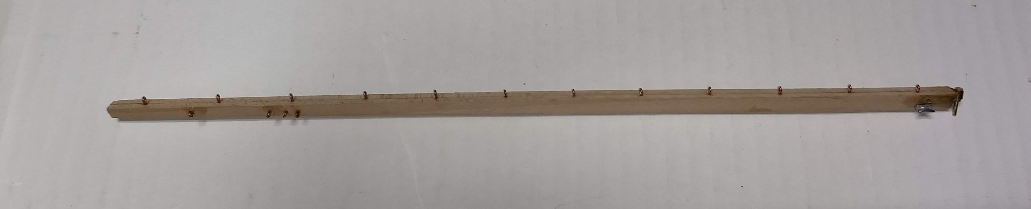
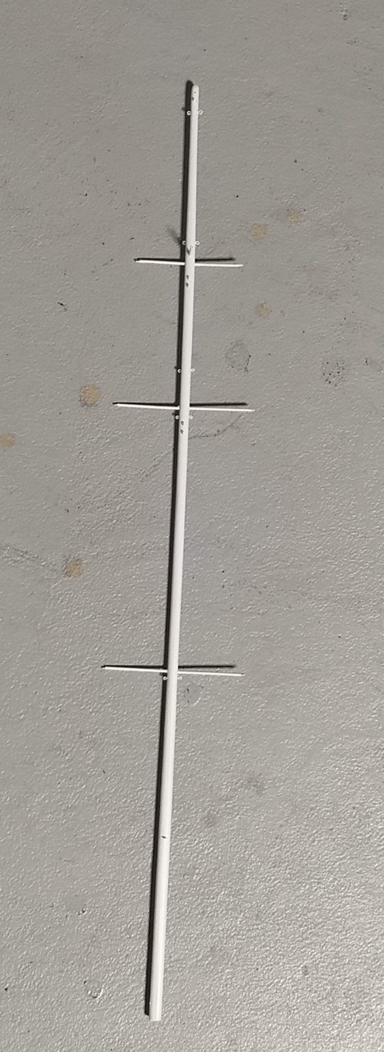
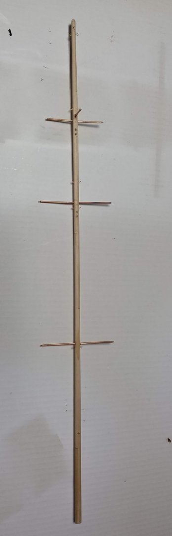
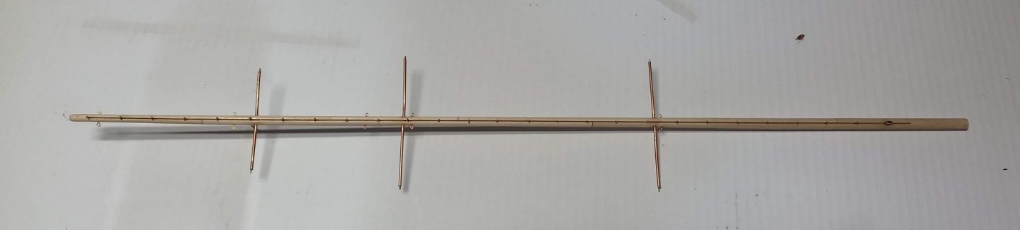
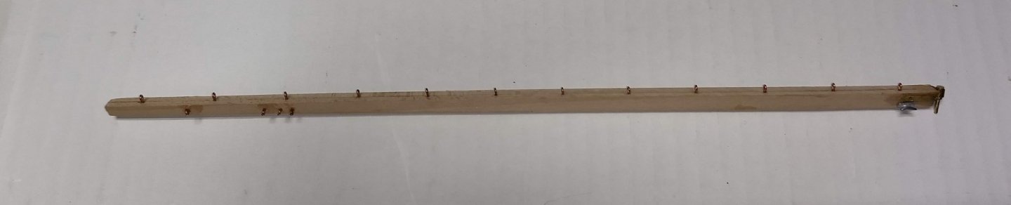
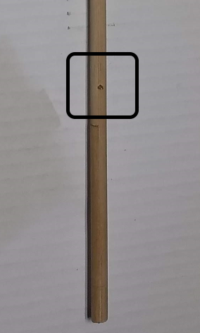
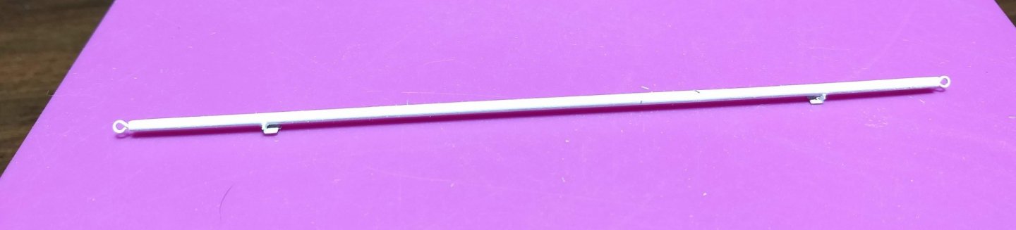
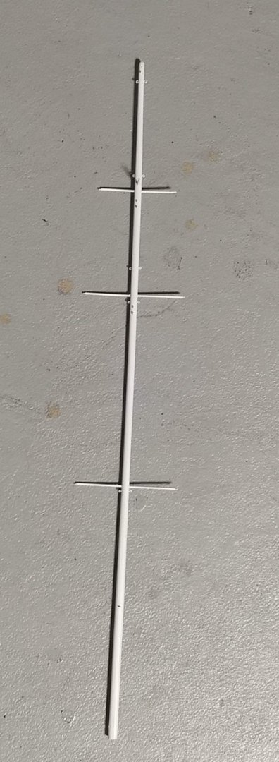
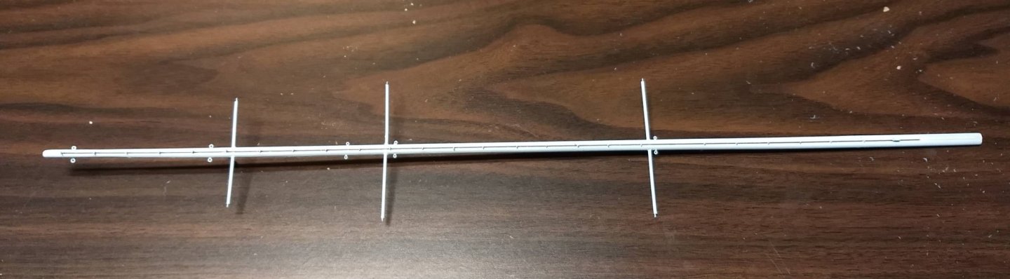
cornhusker1956 Interesting about your thought of planking from the inside out. I had thought about that, but since the last few rows get smaller and smaller I always thought it would look better if the smaller planks were on the inside. But I have not seen that, so I can not say I really have a valid thought. I will take a look at your Bluenose and Pride of Baltimore logs to see what inside out planking looks like. I also used planked the first row of the deck in mahogany (or what amati calls mahogany strips). I had a few strips left over from the 2nd planking. I did not have enough mahogany strips for that and a middle strip. I still wanted a dark strip down the middle, so I had some leftover walnut from a previous ship (king of the mississippi) so I used that down the middle. Not quite the same color, but I like it. You will see some pictures later on in this post. Anyway,,, back to the Endeavour... At this time I figured it was time to do the mast and boom. With the mast nothing really exciting. Only thing of note was that the instructions call for .5mm holes to hold the eyelets. I do not have a calibrator to verify so my bits may be off, but my .5mm, .55mm, and .6mm bits were too small for the eyelets. I found I had to use a .65mm bit for all the eyelets holes. Either that of my bits have gotten mixed up and I really was drilling a .5mm hole. Anyway there are a ton of eyelet holes to drill. I have a small electric drill so the task was not that bad, but I really do not recommend you attempt this many holes if you only have a pin vise.... You will go crazy. The Endeavour has a spinnaker pole, but no fitting on the mast to attach it. Not a big deal, but I added an eyelet on the front of the mast that show where the spinnaker pole would attach to the mast. You can barely see the eyelet on the above picture, so it is blown up below. Here is the aft side of the mast. Not here I decided to not have the groove go the entire length of the mast. In a real boat the slot of the sail is just that,,, a slot for the sail. See the slot start a little below the goose neck on the bottom of the mast and slot stop short of the top. Not a big deal, but just looked better to me In regards to the boom, I did a little more customization. In my case I do not plan to put the sails on the boat. To me the rigging looks great all by itself and the sails detract from it. Since no sails, I decided not to put the long rod along the boom that he sail would attach to. Instead I just lined the boom with more eyelets similar to the mast. Many will not like that, but to me it just looks better than the long bar is you are not going to put up the sails. One note,,,, if you plan to put eyelets on the boom, you will have to acquire some more eyelets. There are not enough extra eyelets included with the kit to allow for eyelets on the boom... Nothing new here other than a paint job On to the spinnaker pole. I could not find any written documentation on the spinnaker pole. However if you look at the drawing showing the mast and boom, there is also a picture of the spinnaker pole. I guess you just have to know to build it. Nothing to it,,, just have to put an eyelet at each end of the spinnaker pole and glue on the fitting that attache it to the deck. I strongly suggest a vice and an electric drill. Even though the .65mm bit is small, the spinnaker pole is not much larger. It takes a steady hand to drill the holes at both ends of the pole. I know I could not do it what a pin vise. On to the decking.... Since the hull will be mahogany the first few planks around the deck probably should be mahogany. I a few strips left over from the 2nd planking. Doubling them up (each is .5mm thick) you end of with a 1mm thick plank. For the center plank, I did not have enough mahogany left over, so I choose some walnut from a previous ship. The color does not match, but after a light stain they will be pretty close - or at least that is what I hope. 🙂 Only big issue is you will have to create a custom curved stern planking section. My stern piece is not museum quality, but for a beginner I think it turned out OK. As for the deck planking, I pondered for a long time as to what was the best deck layout but I don't think I found it. In my case I cut the planks in 10mm sections and staggered them. Originally i thought this would be a good look, but now I am not so sure. It results in a lot of cuts (10mm) and I am not sure I is any better (may actually be worse) than if I has used 20mm sections or maybe mostly full planks. Anyway, this is what 10mm planks sections look like. I also used the standard pencil lead on the plank edges technique to simulate the caulking between the planks. Below pictures show my progress to date.

- 45 replies
-
- 6
-
-
- j-class yacht
- amati
- (and 2 more)
-
Eamonn, I did purchase one of those Waterline Marker doodahs from Model Expo.. Only $8 (us). I will let you know how it works out.... One potential problem I see.... with my dark hull, not sure how well the pencil line will show up. Hopefully it will be as you say..."easier than it sounds" we'll see
- 45 replies
-
- 2
-
-
- j-class yacht
- amati
- (and 2 more)
-
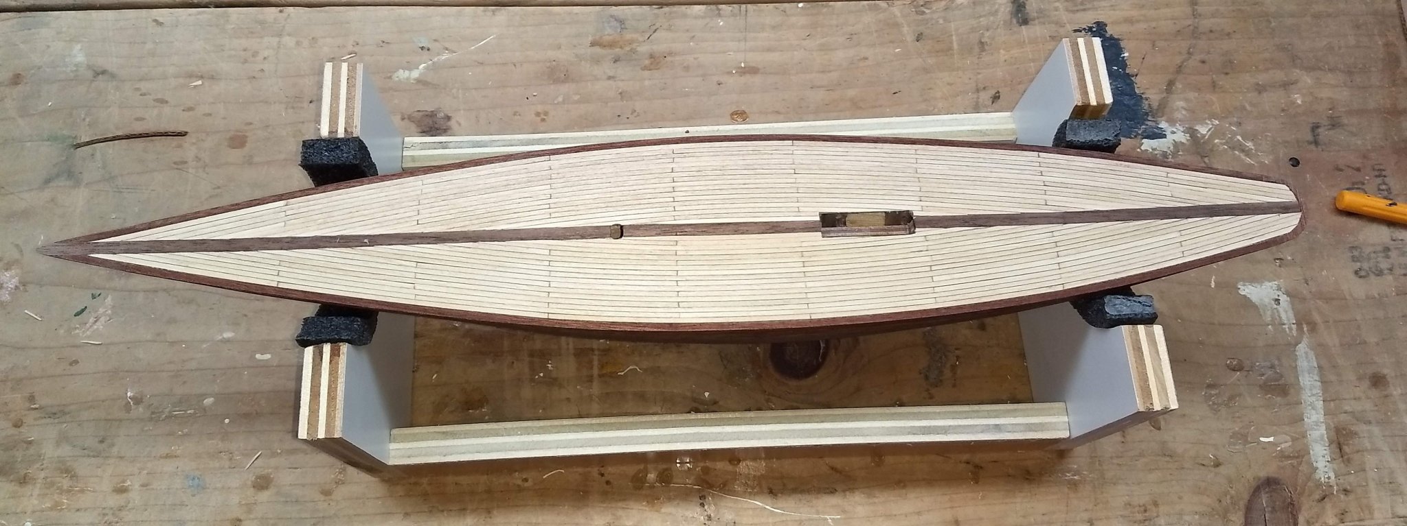
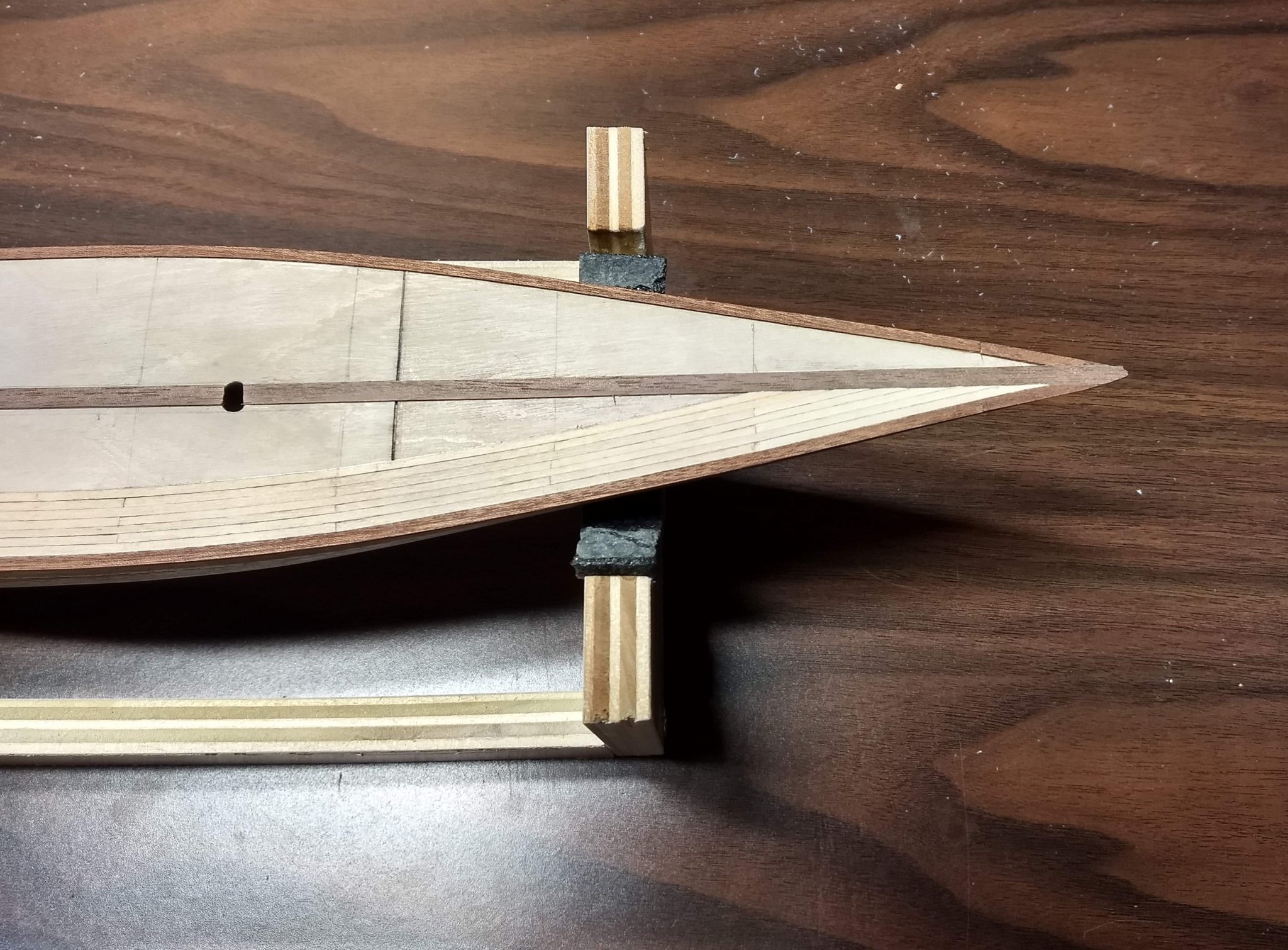
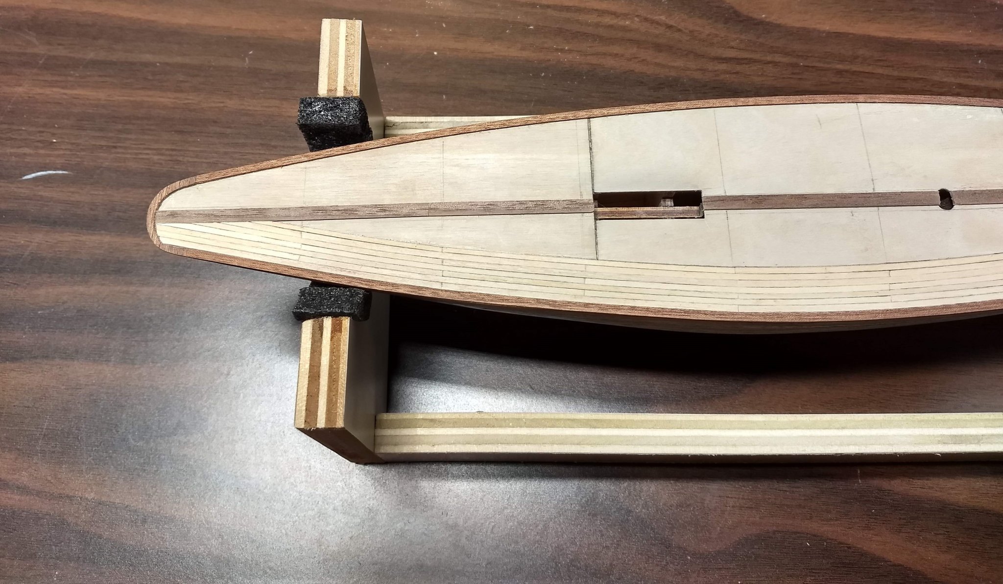
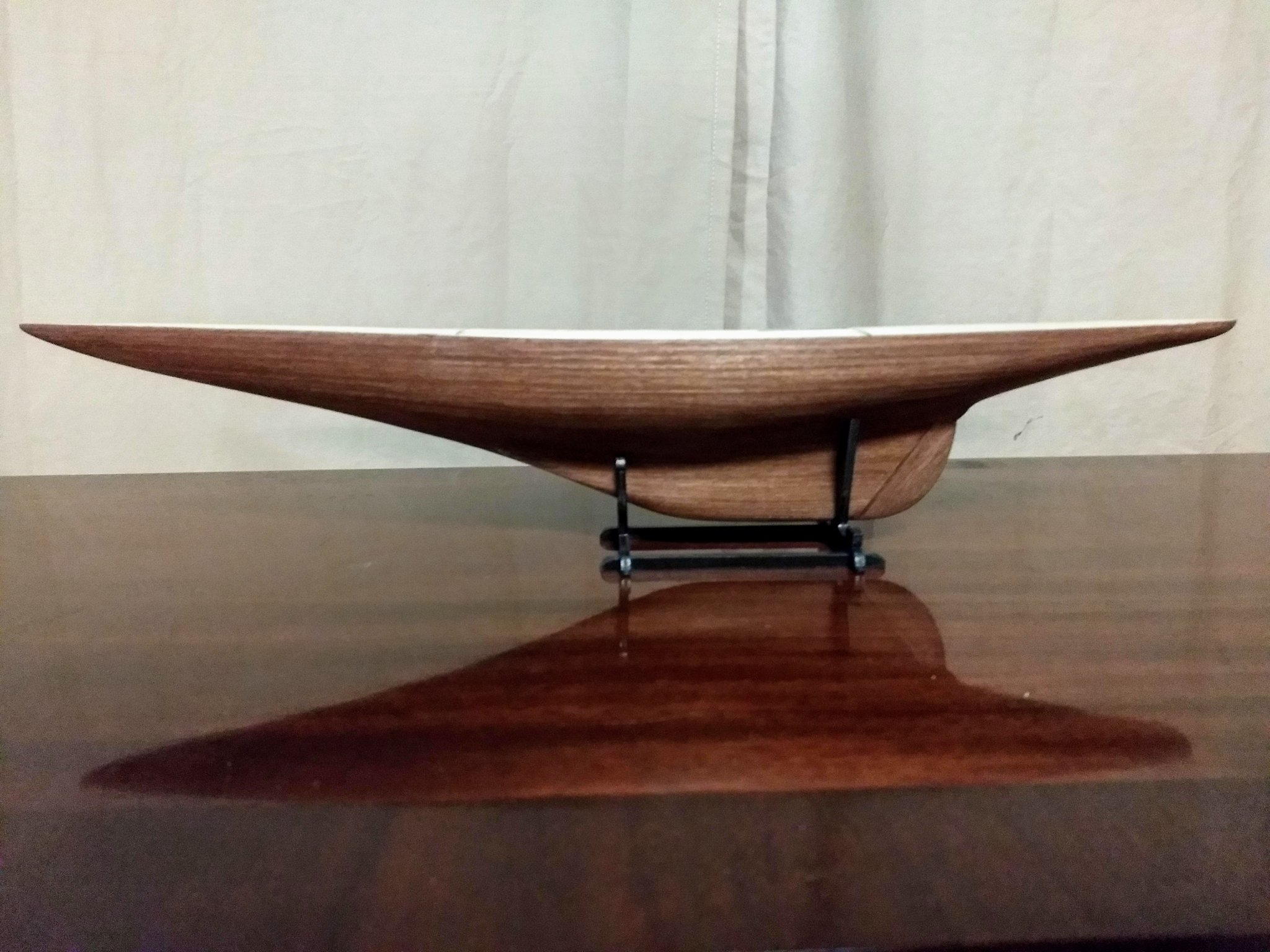
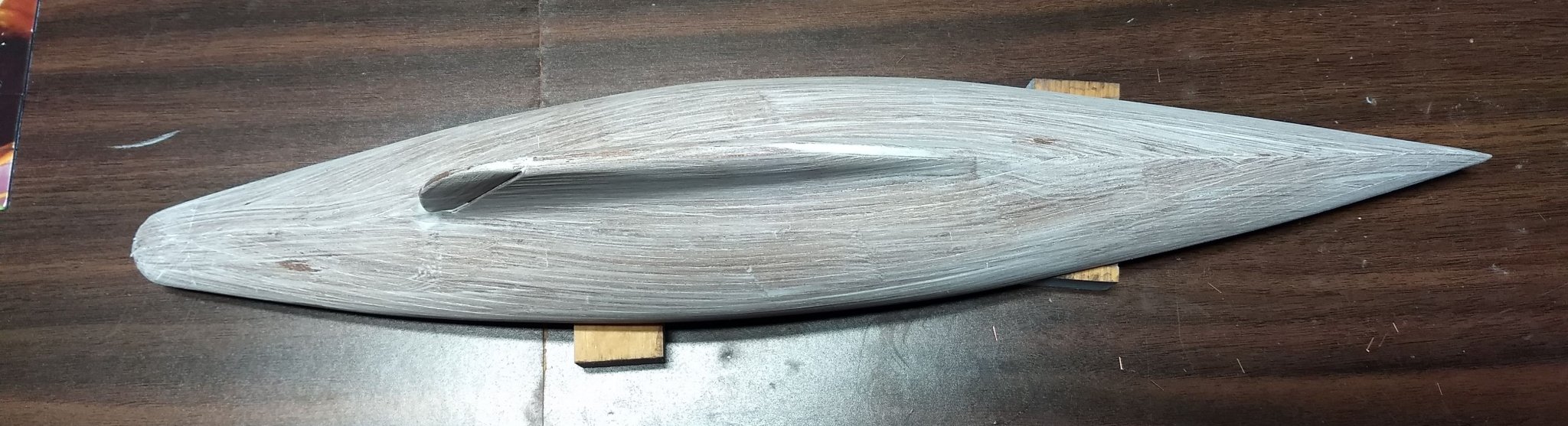
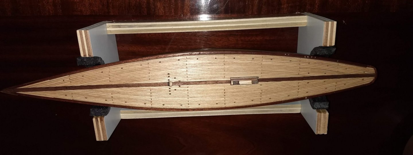
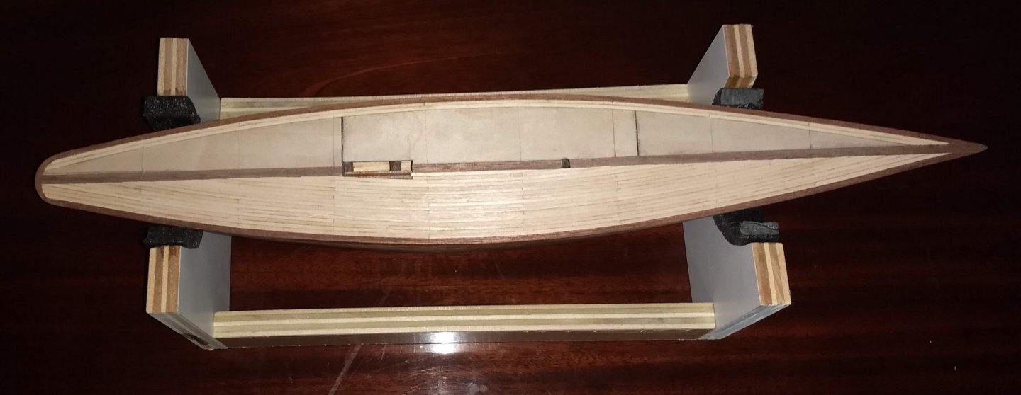
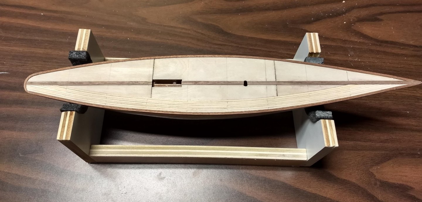
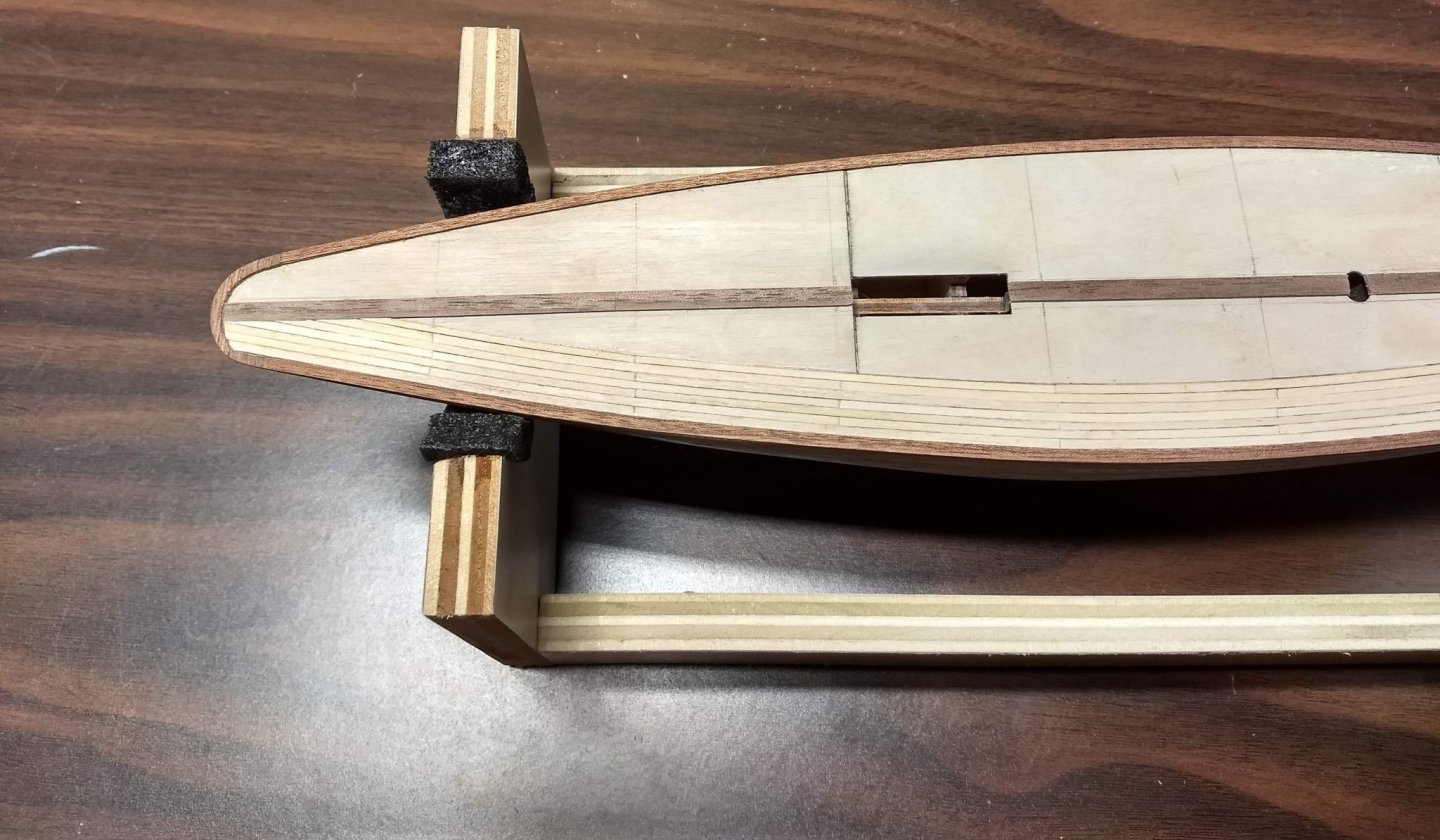
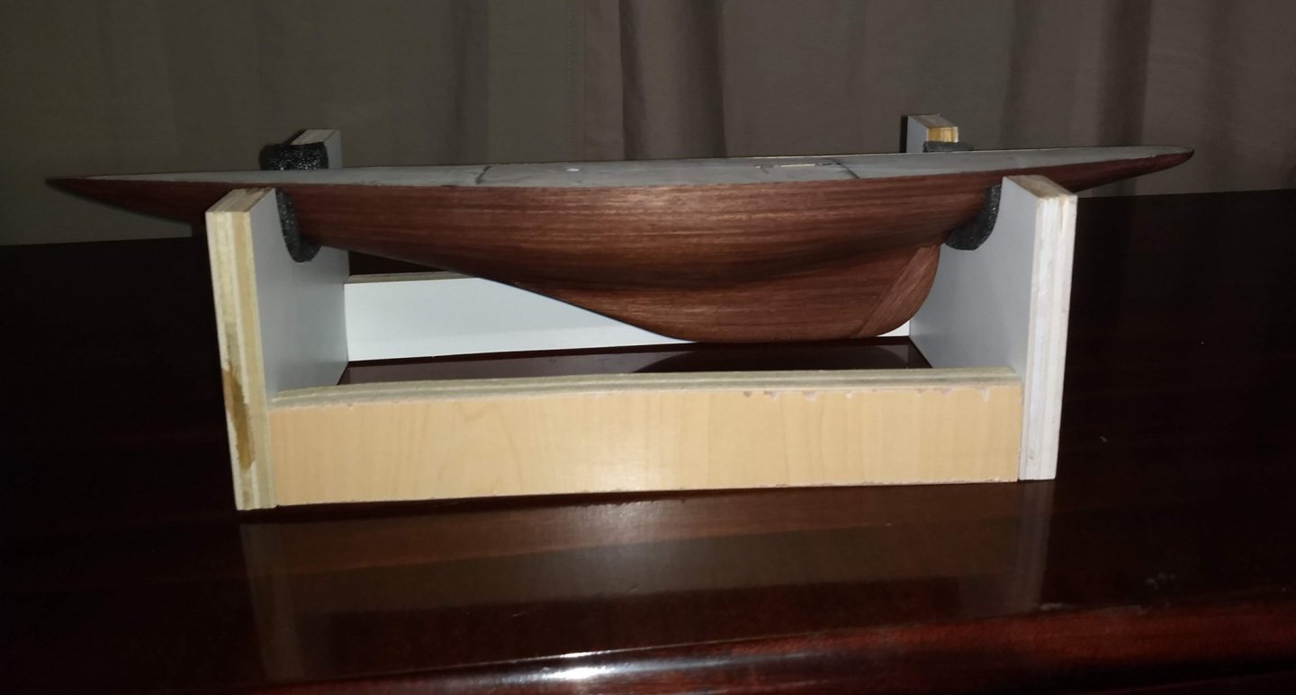
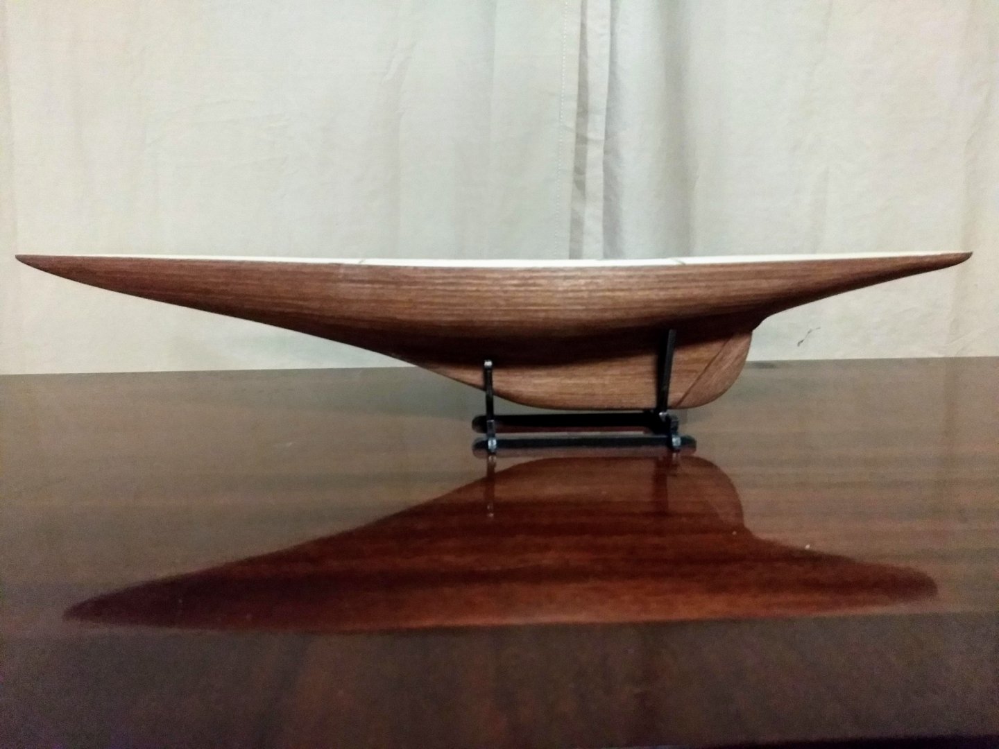
One final picture before I start the decking. I need to still put a white water line on it, but at the moment a little to scared. Not screwing up the waterline and getting it right will be a challenge for me. Before I start the decking, I wanted to build a stable cradle to hold the ship. Up until this time I the Endeavour has spent most of the time on my lap with the 1st and 2nd planking. With the decking and deck fittings I can see where a steady cradle to hold the boat would come in handy... So with some spare wood and a hour or so (most of the time trying to figure out the design) the cradle was formed. Hopefully it will be worth the effort.
- 45 replies
-
- 6
-
-
- j-class yacht
- amati
- (and 2 more)
-
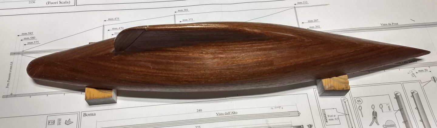
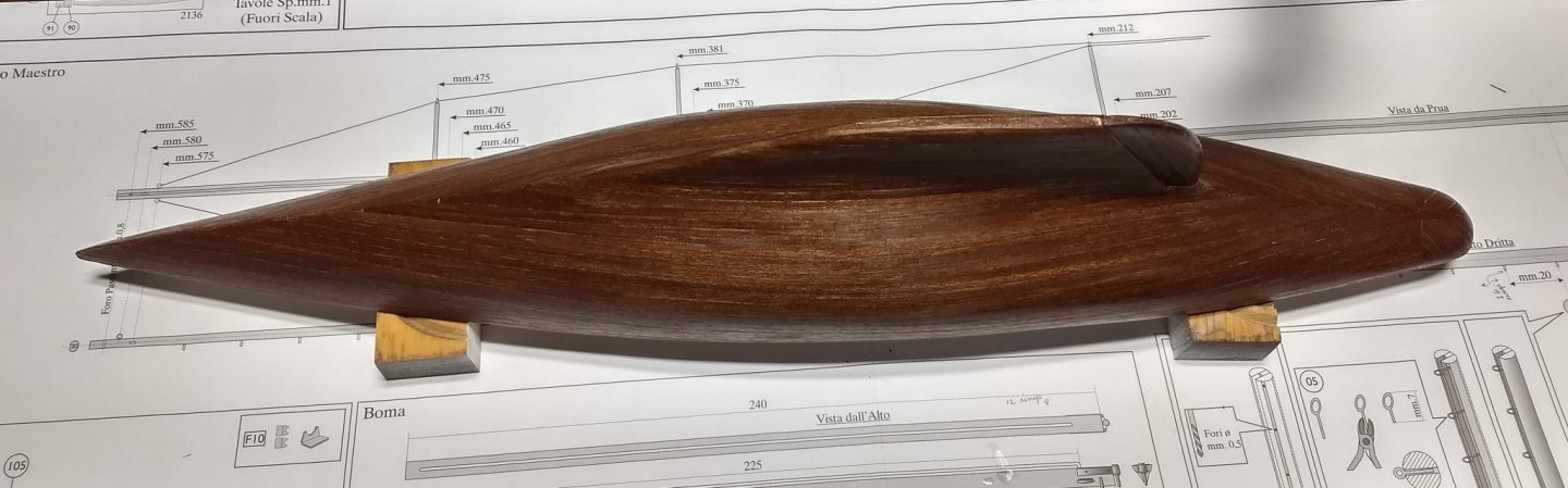
cornhusker one more comment on "filla-in-a bag".... It is a powder that comes in a number of colors. In my case, do to my lack of knowledge/skill I ordered the pine color, as it seemed would match the pine like first planking. In reality you should order the color that most matches your final paint or stain.... As a result, there were a few"pine like" spots showing between some of the 2nd planking where the planks did not fit snugly. Not a big deal as when you sand the boat, the seams all merge together and you no longer see the filla between some of the planks. Next boat I will add a little paint color to the next batch I make. With the 2nd planking complete I wanted to use from grain filler. Never used one before, but I had heard it is the thing to do to get a smooth final coat. Since I had great experience with "filla-in-a-bag" I ordered GoodFilla CLEAR Water-based grain filler. Here is a case of do as I say - not as do. The instructions indicated the grain filler would go on and dry white. Then with a wet rag, the white can easily be removed and the grain filler will turn clear when coated. The grain filler when on really smooth - the consistency of smooth white glue - and did dry white. Pretty scary if you want a clear finish In my case I came back the next day to wipe off the white. Even though I rubbed somewhat hard, there were still some white strips in between some of the planks. I was a bit worried, but with some sanding and a little stain, the white strips disappeared.. While I did not like the fact that I could not get rid of all the white with the cleanup, the end result was a finish as smooth as glass and the poly went on smooth. Not sure the moral of the story... I have not used grain filler before so for all I know they all go on white. It was probably do to my lack of skill and I must have done something wrong with the grain filler, as all the white was supposed to go away with the light wet rag... Not sure what I will do next time other than try it again. All came out in the end as below shows the final result after 2 coats of poly. I will probably go on to the deck next and when complete will probably come back to the hull with another coat
- 45 replies
-
- 5
-
-
- j-class yacht
- amati
- (and 2 more)