


Martes
-
Posts
809 -
Joined
Content Type
Profiles
Forums
Gallery
Events
Posts posted by Martes
-
-
2 hours ago, Chapman said:
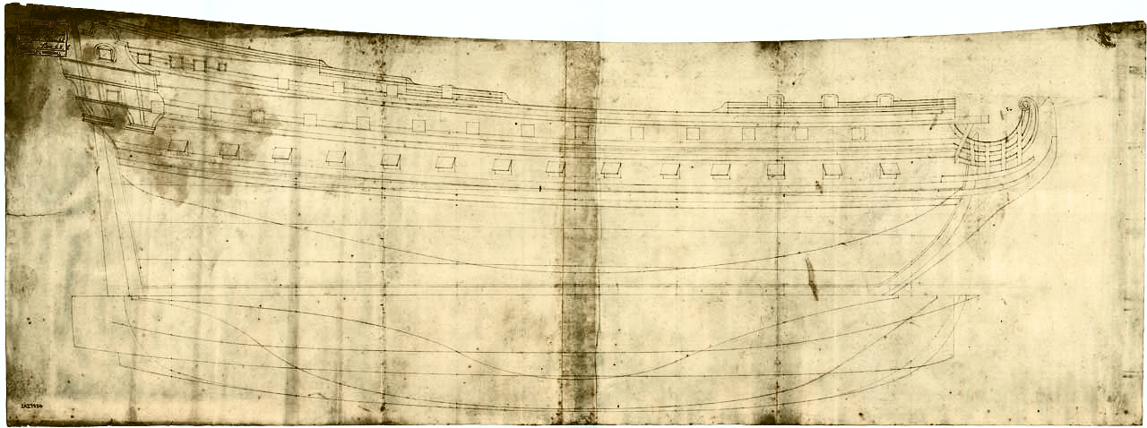
It's great that there is a plan for this ship as it was built and the decoration as planned. This gives good insight into the final execution.
It's slightly more complex than that, since the Prompt was heavily rebuilt in 1698, and the decorations could have been altered or replaced.
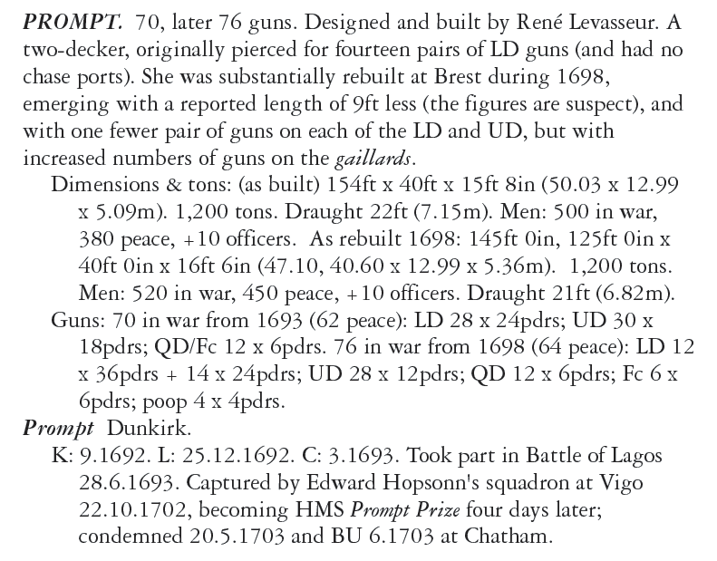
Whether she was shortened or not can probably be verified by her British plans
https://www.rmg.co.uk/collections/objects/rmgc-object-87616
https://www.rmg.co.uk/collections/objects/rmgc-object-87615
But it is relatively difficult in the available resolution and with no apparent scale.
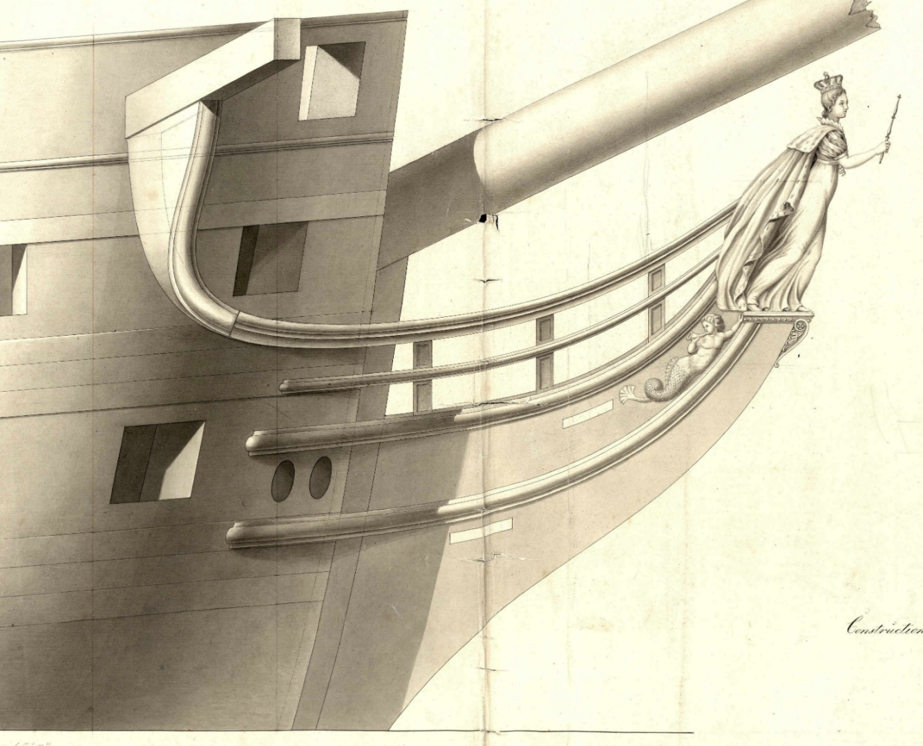
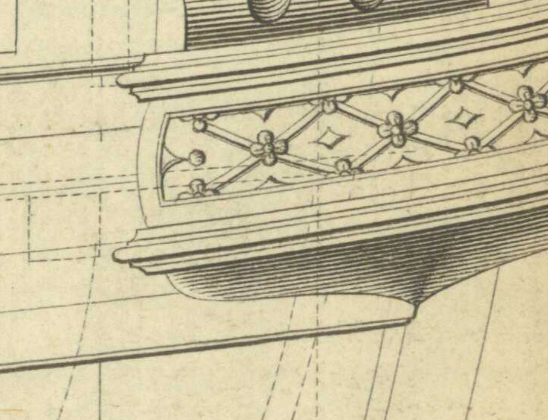
Still, the Louvre views show that the quarter galleries were at least designed in a style very similar to the Fulminant.
- Theodosius, mtaylor and HAIIAPHNK
-
 2
2
-
 1
1
-
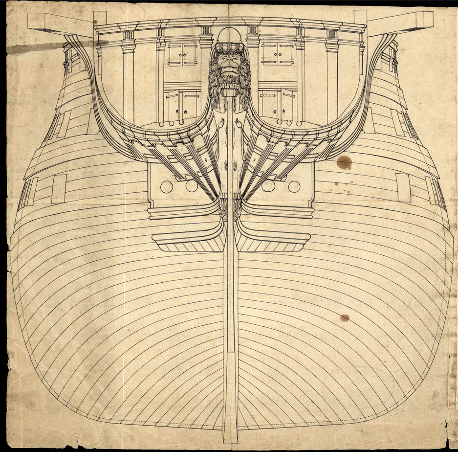
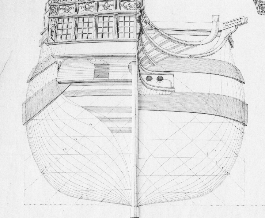
The British plan of the captured La Prompt may also provide some hints as to the construction of the gallery:
- mtaylor, Theodosius, empathry and 3 others
-
6
-
wale = бархоут
And the structure is indeed called a quarter gallery.
I am not sure about the compression, though.
If this depiction is of any reference, it shows the quarter galleries to be very long, reaching the aftermost gunport on the lower deck, and it is consistent with the archive design.
-
-
5 hours ago, 3DShipWright said:
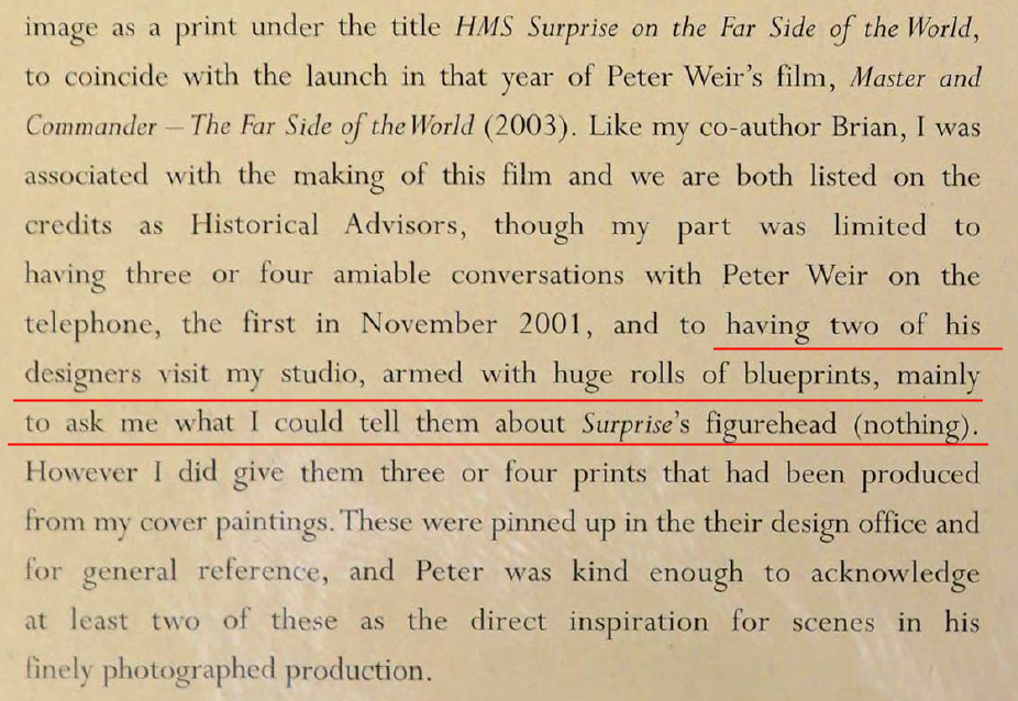
I'm curious, when Hunt writes "... (nothing)" does he mean he had no information to give Weir, or that there was no figurehead on the original HMS Surprise (HMS ROSE)? It could be interpreted either way.
As I understand it, Hunt meant he did not have any specific information about the figurehead apart from the original plans.
The original figurehead of the Surprise/Unite was, by the way, a decorated shield covered by Phrygian cap, not a human figure, and it is unknown if the figurehead was ever replaced in British service.
Your very basic option is white, as most sculptures were made to imitate marble, and this is relatively in line with architectural style of American country mansions. It is possible to use gold/yellow paint for small details, but generally, most of depictions of American ships show white where the British or the French put gold.
Most, but not all, and the second option is yellow/gold:
The third option is painting them live colors, imitating skin and clothing. It is also not unknown of, at least a model of New Orleans (the lake battleship) features the stern decorated in precisely that style.
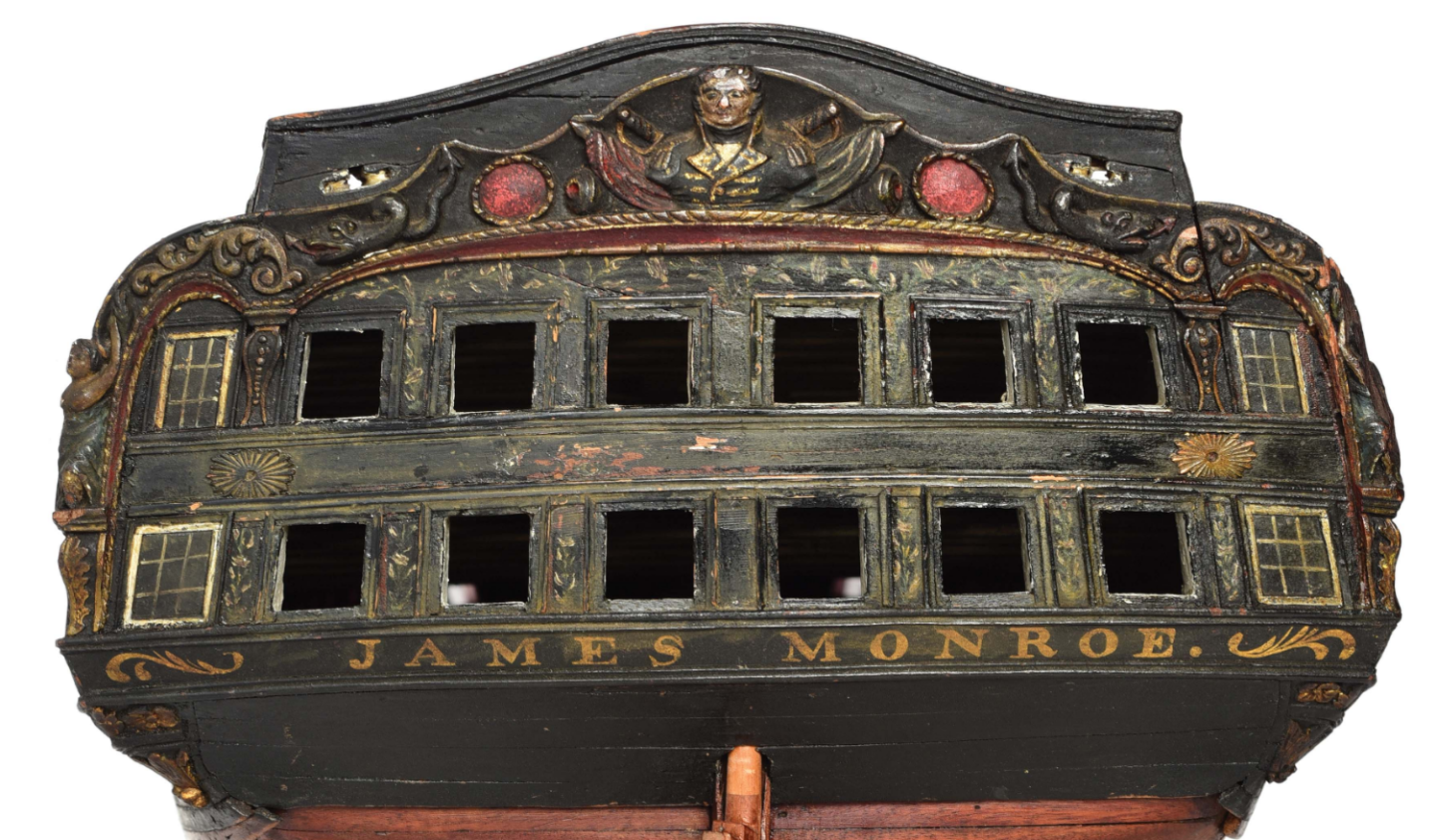
And for one of the big frigates (either Constitution or the President) as well:
- mtaylor, 3DShipWright and wernerweiss
-
2
-
1
-
I am not sure those sculptures ever had plating that could be replaced, but there are probably ways to grind a metal or glass (see below) into the paint to achieve similar effect. Most of the paints were made of mix of metallic or mineral powders, after all, and many were poisonous as hell. It's all question of a budget.
Nate, I'm not saying it's impossible, just that it's expensive, but if they did invest into decorations, than, actually, why not. But to provide copper plating for sculptures and save on coppering the ship's bottom is a new low.")
Also, note that the current Rose/Surprise figurehead is not very historical and most of the existing evidence points that figureheads in late 18th century were either whitewashed (to resemble marble/ivory) or painted in live colours.
It is possible, however, that greenish mould could produce similar effect on fading and salt-covered white paint.
Geoff Hunt mentions in the book on the Surprise:
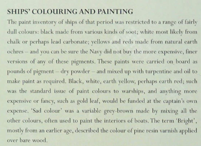
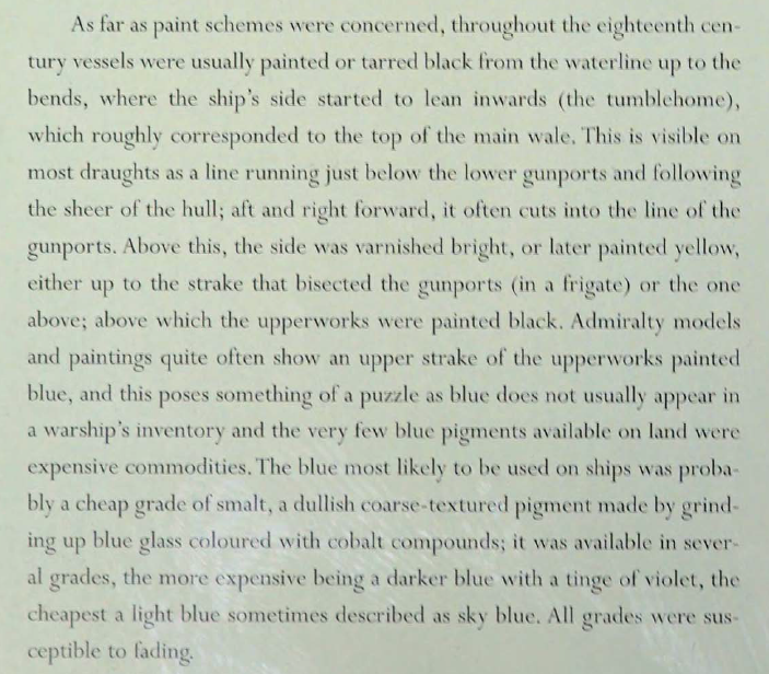
And concerning paints in general:
-
The sculpture colouring is very good-looking, but I rather doubt it's realism. All the carvings were, obviously, made of wood, and usually would be painted either white (as the most accessible and cheap paint) or, if the captain had means to do so, gilded. At least in Britain this was done out of captain's pocket, not the Admiralty, and I think in the early US there would also be some budgeting problems to produce and provide the ship with very special paint intended only for part of the decorations.
-
I ran into a plan suggesting a very early (~1728) Danish use of gradually increasing width of the planking towards the lower wale:
(see G2846, Prins Frederick)
https://www.sa.dk/ao-soegesider/da/billedviser?epid=17149179#188975,31896027
And, by the way, note the difference between this forward view and side view of the bow/stern that is attributed to the same ship under G2845
https://www.sa.dk/ao-soegesider/da/billedviser?epid=17149179#188975,31896025
-
-
8 hours ago, Bruma said:
May I ask you what game engine you are using?
It is an existing game, called Age of Sail II: Privateer's Bounty. Released in 2000, or thereabouts. I just found the right converters and went as deep into the parameters editing as it was possible.
I did some experiments in Unity, mostly to see how cablework can be implemented, but models do eat most of my time.
8 hours ago, Bruma said:why aren't you upgrading to a newer version?
Got too much used to 2.79
Besides, the workflow requires exporting the model to OBJ and then to special converter that creates the game model, so it ultimately does not matter. I tried newer Blenders for terrain generation (blenderGIS, and all that), but I haven't yet figured out a way to make this process (conversion of GIS data to game-specific format) convenient enough, so it's shelved for the moment, and it would be redundant if I ever switch to Unity.
Why?
-
-
5 hours ago, allanyed said:
Martes, this is important and it did change over time. The thicknesses of the wales and planking above and below varied with size of ship and era even within just the English Navy.
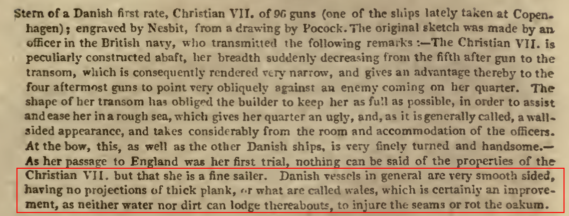
If I remember correctly, the smooth transition to wale was initially French fashion, but the Danish ships definitely made an impression, as their description in the Naval Chronicle specifically mentions the smooth sides, see Vol 19
https://archive.org/details/navalchronicleco20londiala/page/n13/mode/2up
-
4 hours ago, Jaager said:
Monarque/HMS Monarch will be a challenge. The officer who took off the lines of that capture only drew the absolute minimum number of stations. The work to get the timber patterns will be less, but the frame sections will be very fat - too fat actually. I will probably subdivide by replicating stations and then have a lot more shaping of the joined sections.
The plan for the Monarque includes design diagonals, which should make restoring the missing lines relatively straighforward. And there are two additional stations forward marked in pencil.
Additionally, there is a Danish copy of the plan (possibly obtained by Stibold in France) in the Danish archive, number F163, and the 74-gun Pembroke of 1758 was her direct copy.
-
Why, there are wales, they are just barely visible. But you can see the top border:
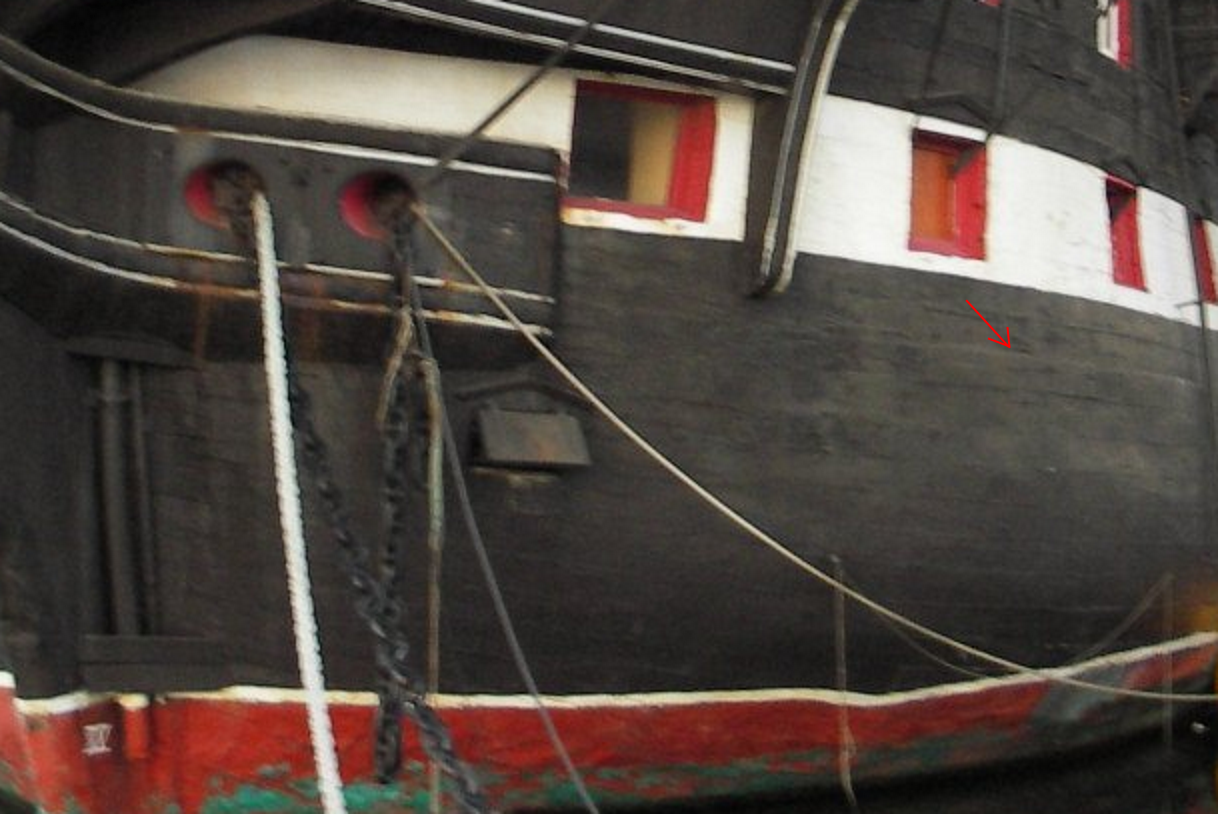
And see how smoothly they are integrated into the planking:
https://www.rmg.co.uk/collections/objects/rmgc-object-81777
I chose the starboard side because there was no plumbing obscuring the intersection with the rabbet.
-
-
On the other hand, on the Danish ships, at least later ones, where the wales were almost indistinguishable from the rest of the planking (the planking became gradually thicker towards the wale) the line of the wales at the rabbet was uninterrupted, with, apparently, all planks brought to uniform thickness on the ends:
So it really depended on the construction school and period.
-
It should not be, however, taken as a universal rule.
The plans for the Dutch Utrecht, for example, definitely show the wales to explicitly protrude over the planking at the rabbet:
-
2 hours ago, allanyed said:
That being the case, how does it sit in the rabbet? Must it be carved to sit in the rabbet with a little sticking out or is the rabbet chiseled to accept the full thickness of the end of the wale?
I suppose the first case, "carved to sit in the rabbet with a little sticking out".
- mtaylor, thibaultron and allanyed
-
3
-
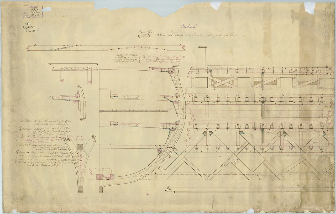
Maybe this plan can provide some hints.
The wales seem to be narrowing towards the bow, but they are still extending slightly beyond the surrounding planking when reaching the keel.
- mtaylor and thibaultron
-
1
-
1
-
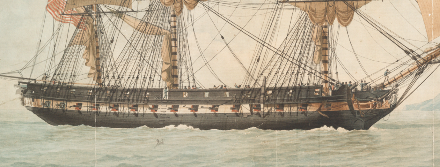
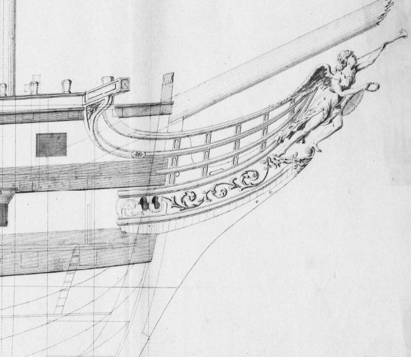
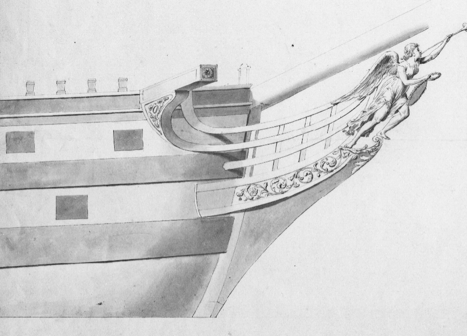
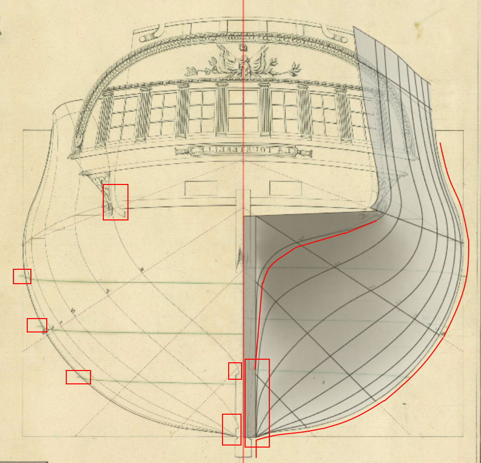
Also note the differences between the French configuration on the main plan
and the alterations done in British refit on the inboard plan
https://commons.wikimedia.org/wiki/File:Tourterelle_(1795),_ex_French_(1794)_RMG_J6362.png
and the differences between Tourtourelle and Unite/Surprise.
https://www.rmg.co.uk/collections/objects/rmgc-object-82858
Surprise had the forecastle barricade completely enclosed, the head was lighter and the bridle ports moved forward of the catheads.
From my experience, the detailing of the positions of the bridle ports, cheek pieces and hawseholes on profile plans are in many cases quite inaccurate (to the extent that different shipyards could interpret the same plans differently), and do not always take the curvature of the hull forward into account, so that if you follow the plan exactly you can end up with very stretched and unnaturally looking result. It takes some trial and error to get it right.
-
Thanks, @Kestros1
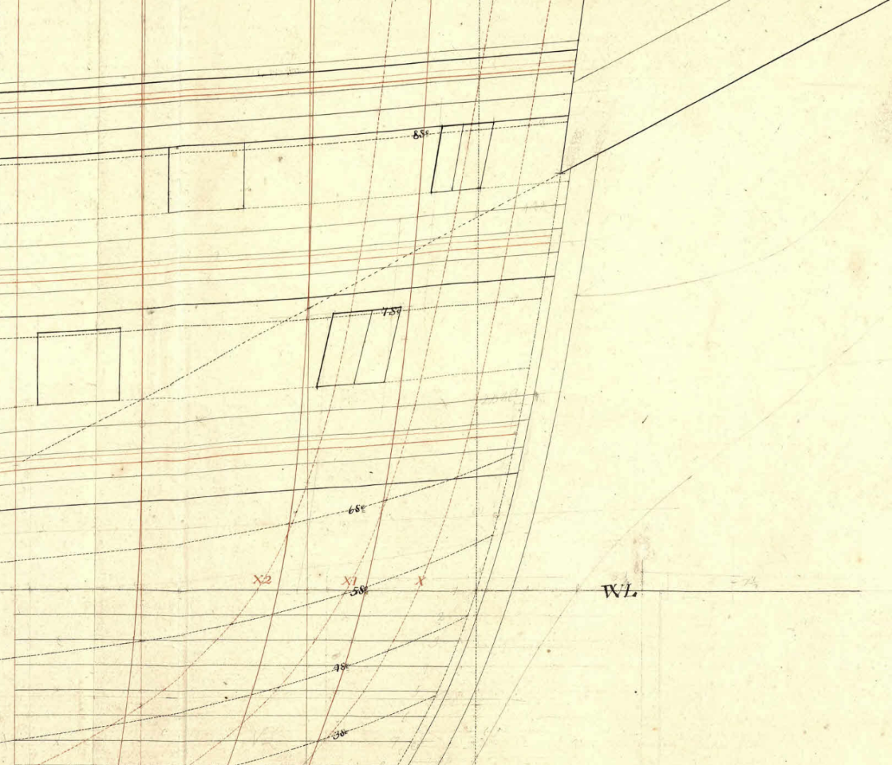
Indeed it is much better, but it still ignores the planking, that that should look something like this (this plan is for a different ship, of course):
The lines on the original plan are dashed, the planking thickness for each frame is in solid lines. Note, though, that especially on the rounding of the bow, the plank thickness is perpendicular to the surface, and thus in the transverse cut will appear significantly thicker (see this post where I explained it, for example).
So your real outline, accounting for the thicker keel, should look something like this (note the waterline marks, the give a rough idea of the planking thickness in corresponding places, as well as the steps at the intersection of the frames and the keel):
It is possible, Fusion 360 has some feature to automatically make an envelope of at least fixed thickness around a complex mesh that follows the frames (like Solidify operator in Blender) that make this process somewhat easier, but I haven't found any reliable way to do it except manually.
-
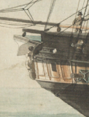
I am very much afraid it is little late, but hawseholes really ought to be closer to the centerline, and their cuts are parallel to the centerline, not perpendicular to the surface of the hull in the place of the cut.
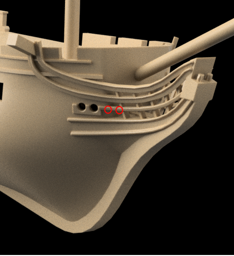
And by the way, why the sudden rectangular cut of the bow? It was round on those ships.
-
27 minutes ago, Kestros1 said:
followed the frame lines, did not even consider the planking thickness.
It's a very common error, everybody falls for it at some point.
Planking may appear something thin and negligible, but in fact it adds a very substantial volume to the outside form of the ship.
Also note that it's the thickness is not uniform, and the planking is thicker towards the wales.
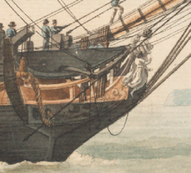
Figures in the great cabin is a very nice touch. Will the top cabin be removable to manipulate them?
-
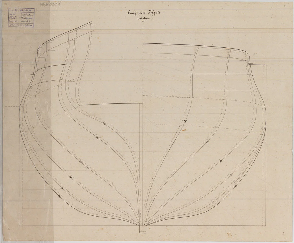
Does the model include the planking or not?
The front view makes the hull appear as if it includes the planking. The stern view shows the hull as if it follows the frame lines.
By the way, there is a good quality set of plans of her sistership Tourterelle on wikipedia:
It shows the French configuration, but it may be of assistance.
I suppose the extremely wide keel is for the plastic endurance, but those small frigates never had the poop cabin aft even in French configuration, and the deck should not be flat, but slightly curved towards the centerline.
- tormat, mtaylor and uss frolick
-
3


_RMG_J3059.png)
,_ex_French_Tourterelle_(1794)_RMG_J6363.png)
,_ex_French_(1794)_RMG_J6362.png)
French FULMINANT rear castle
in Building, Framing, Planking and plating a ships hull and deck
Posted · Edited by Martes
The final configuration for the Prompt is 14 pairs of guns on MD, so the aftermost rectangle is most probably not a gunport, but a window.