


Leopard
-
Posts
32 -
Joined
-
Last visited
Content Type
Profiles
Forums
Gallery
Events
Posts posted by Leopard
-
-
It takes a bit of searching on eBay, but you can find vintage/antique ivory piano keys for not too much. Here's one listing.
Piano keytops range somewhere between 1/8" and 1/16" thick. It might not work for the bulging portions of the figures, but the large flat plates might be useful for the background relief carvings.
I got a free piano a couple of years ago and was very seriously looking into restoring it. In the process I found out that you can't buy new ivory, but it's perfectly legal to buy existing manufactured goods made from ivory. You can't import or export it though, the sale has to be local (national).
In the end I decided to use maple veneer for the keytops and then eventually just got rid of the thing, since it would have soaked up too much of my time. It would have been a fun project, but there are many other things that are higher on my list.
-
-
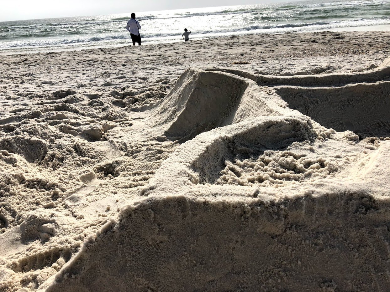
Not the OP, but I just had to show off a bit with this. My son and I built a star fort on Orange Beach in December. He did the gateway (and the little wall around the gateway) by himself. It was fun explaining enfilading fire to him.
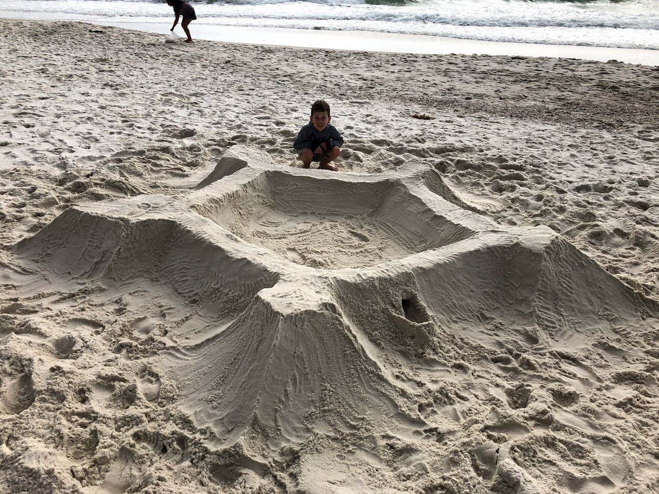
We had started adding parapets when we ran out of time and had to go get ready for dinner.
-
On 11/30/2019 at 4:16 PM, Chuck said:
Just a small update...I have put the seats in the galleries. This means I can start closing them up next. The seats are made of two laser cut pieces that are 1/32" thick. The front panel and the top. You still need to bevel and tweak the edges for the best fit.
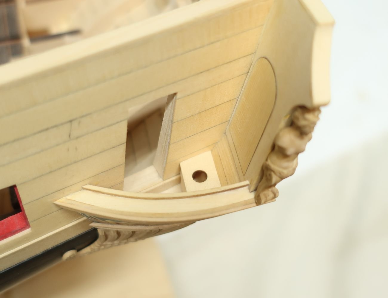
Hi Chuck,
Would there be an outlet hole in the quarter gallery's floor, below the seat's hole? It doesn't look like there would be anywhere for such a hole to go, what with the carved bit supporting the quarter gallery's floor from underneath.
Or does the seat in fact go over a chamber pot? If so, I'm guessing that either the seat or the kick panel would have to hinge to allow removal of said article. Or possibly the seat could just be loose, fitting snugly in the nook formed by the two walls and the kick panel. Then it could simply be lifted off for maintenance access to the enclosure.
- Robert Sargeant, mugje and FrankWouts
-
 3
3
-
Hi Phil,
Thank you very much for the thinking through all of this so clearly. I went through your numbers and they seem to correlate well with what I have, especially taking into account the British vs American mast lengths. Mine are a bit shorter, but then again, I'm partial to the Royal Navy. And my schooner's painted black, with a yellow/ochre stripe in the Nelson chequer.
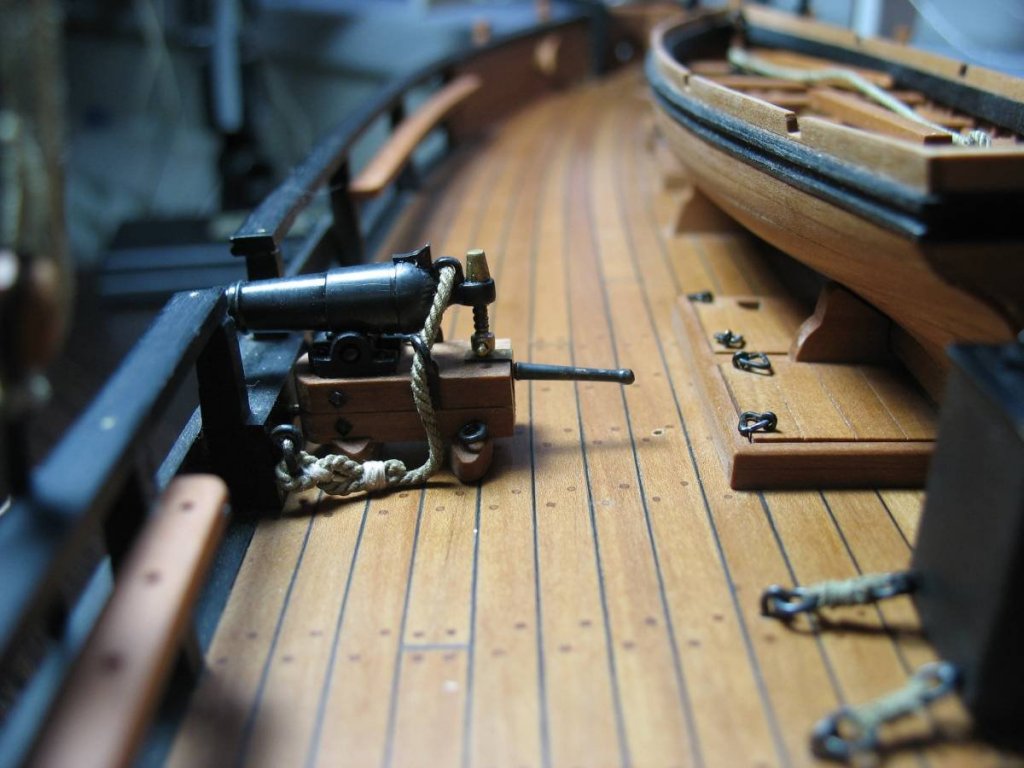
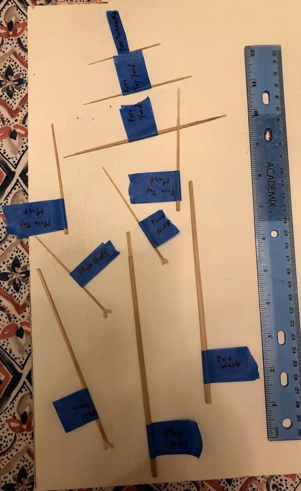
Since my build comes out of a banned kit, I can't show you what the masts look like in situ, but I can show you this picture, since this is all scratch-built from maple dowels I got at Woodcraft:
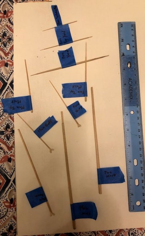
I've since stepped the masts, glued on the cross-trees and and topmasts. Then I went overseas for a working holiday and now I'm building a ropewalk. While away, I sketched out every single line in the standing and running rigging, including all the hardware. Now I just have to finish the ropewalk, make some rope and start rigging. I've made all the deadeyes, but I have a few blocks to go yet, before I'm done. These are all from scratch as well, btw. The kit didn't contain any blocks or hardware. Cheap far-eastern rubbish.
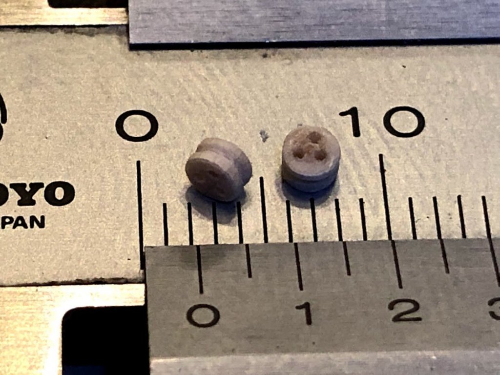
Here's a couple of maple deadeyes. That vernier is in millimeters:
-
On 8/10/2019 at 12:26 PM, Dr PR said:
Maybe the answer is in George Biddlecombe's "The Art of Rigging" from 1925. In Plate XVI (facing page 111) he shows a topsail schooner with a stay running from the main top to the base of the fore mast. He also shows a stay from the main top to the fore top. On page 109, in "RIGGING A SCHOONER" he states "The main-stay leads to the head of the fore-mast, by which means, the the sail abaft the fore-mast is not obstructed when the vessel goes about, as the peak passes under the stay. There is also two jumper-stays, which set up to an eye-bolt in the deck, just at the after part of the fore-rigging, so that the weather one is always kept taut."
I was wondering if both the stays to the deck were rigged at the same time. Only one would be under strain under a given condition (except when the wind was from directly ahead) so the other could be slacked. This may explain the slack line crossing the fore gaff sail in the Pride II pictures - a slack "jumper-stay." Someone who has sailed on the Pride II could answer this puzzle.
I like this interpretation. I think I'm going to go with that in my build.
It just makes so much sense. You still have all the strength of a main stay going straight down to the forecastle, but on one tack you can leave one jumper stay slack. And since the jumper stays might not be quite as strong as a traditional main stay, you also have the stay going to the foremast head. Another benefit is that you don't deviate too far from tradition. You can still be said to have a main stay going to the deck, even though it's only technically true.
-
On 5/16/2019 at 5:26 PM, KORTES said:
I really really like that the ship's boat is mounted on top of a hatch.
The only time that hatch is going to be open is when stores are going in. Stores which are being ferried across by the boat. So there's no time when you'll want to open the hatch without already having the boat in the water, out of the way.
Very clever use of deck space.
- billocrates, KeithAug, archjofo and 6 others
-
9
-
Joe,
In order to understand, I had to draw this one out for myself. Here's the drawing I came up with:
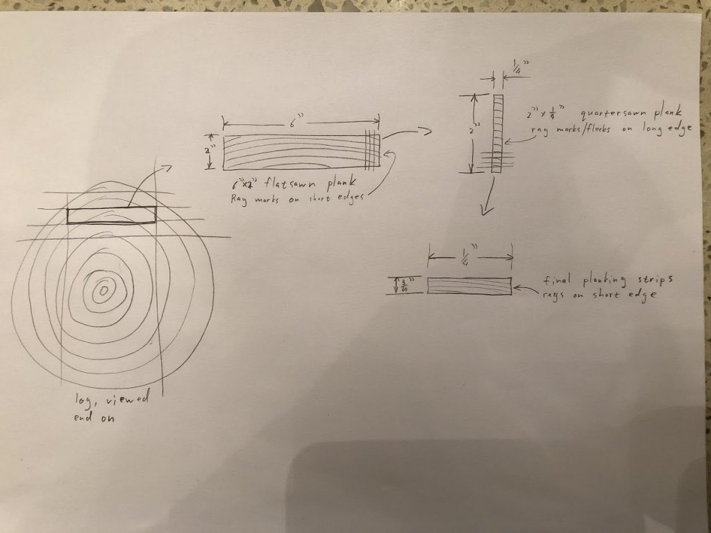
- FrankWouts, mtaylor, JpR62 and 5 others
-
8
-
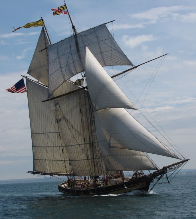
My theory is that the main stay runs from the top of the main masthead to the top of the fore masthead, clearing the tip of the fore gaff. You can see a think line in that area in almost all the pictures, making me think that it's standing rigging.
The taut line (sometimes two) running from the bottom of the main mast head to somewhere around the fore chains is then a preventer stay, used in port (to prevent the masts from rolling out) and in heavy weather (to prevent the main stay from breaking).
The slack lines running diagonally down and forward is then either the fore yard's braces, or the fore gaff's halyards. My money is on the latter. The fore yard's braces look like much thinner lines than the gaff halyards.
That's my 2 cents' worth, anyway. I don't know anything, like you, I'm trying to puzzle this out, bit by bit. I'm currently busy with an untitled Baltimore Clipper build* and the plans have nothing on rigging. The kit also didn't contain any blocks, deadeyes or yard fittings. There was a couple of feet of fluffy brown thread. So fun times.
* I bought the kit inexpensively on Amazon, not knowing the first thing about ship models. After having completed the hull, I found out about banned kits and saw that I had bought one. So now I'm determined to finish it as well as I can, learning as much as I can. After that, I'm buying one of Chuck's kits. As yet I'm completely undecided between the barge, longboat and Cheerful.
-
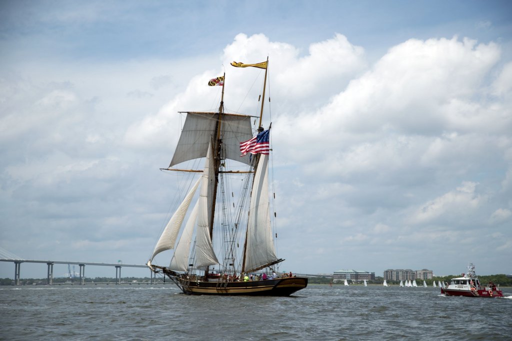
It looks like I left out a picture. It was supposed to be this one:
Here you can see a slack line running diagonally across the fore gaff sail, from the top aft to the bottom forward. Is his the starboard main stay? Or is that the fore gaff halyard?
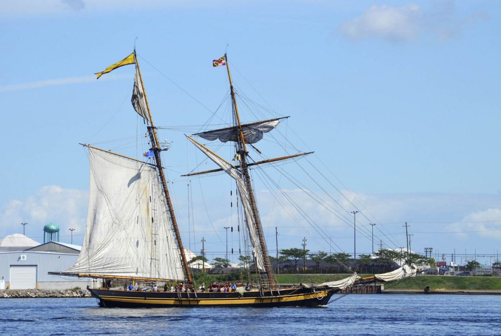
Here's another picture where it's shown clearly:
This picture shows a line running from the bottom of the main masthead (or slightly below), forward and diagonally down and then terminates in a single block. The line that passes through the block looks like it could be the fore yard's port side brace. But it doesn't look like there's a starboard brace, similarly rigged. I can't see a main stay in this picture.
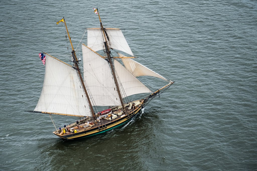
This picture shows no main stay. It does show what looks like dual fore gaff halyards.
And then this picture muddles everything. It shows a fore gaff halyard ... and also a main stay (single, running down to starboard.
- GrandpaPhil and mtaylor
-
2
-
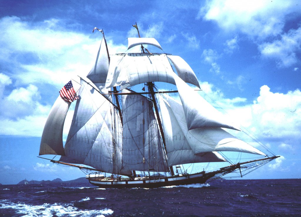
In this picture of Pride II, there are two taut lines runnig from the bottom of the main masthead to around the foot of the foremast, but close to the bulwarks on either side. Are these the dual main stays?
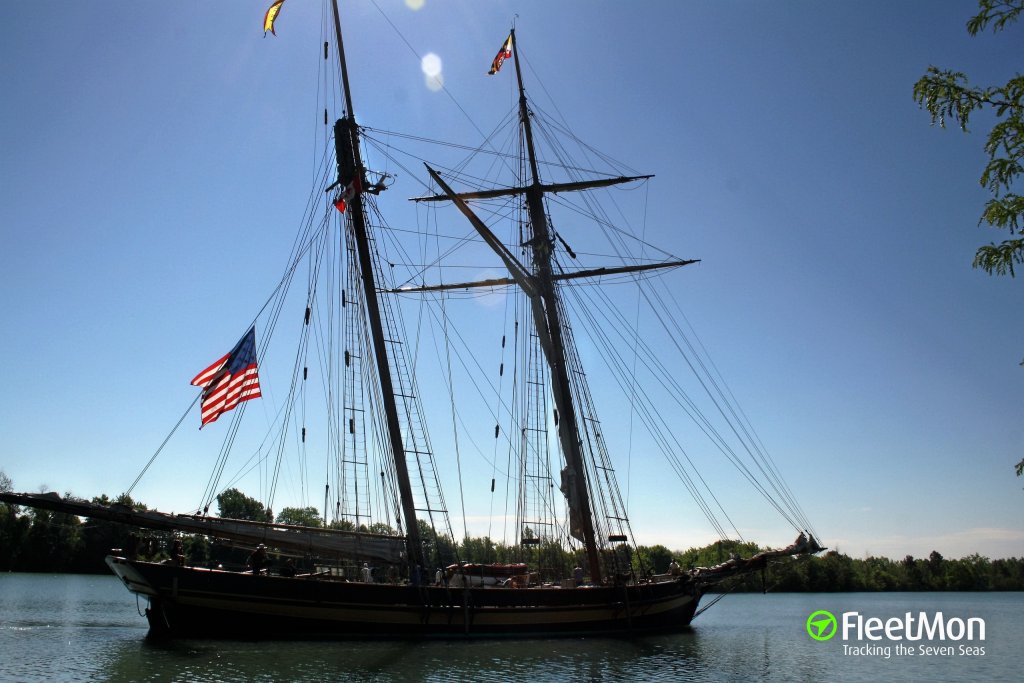
And then in this picture (also of Pride II), there's a slack line running diagonally across the fore gaff sail, from the top aft to the bottom forward. Is his the starboard main stay? Or is that the fore gaff halyard?
If that's not the starboard main stay, where is it then? Or was that dual main stay only rigged as a preventer stay while in port?
As to the original question, Chapelle mentions (in The Baltimore Clipper, but I can't remember exactly where) that the main stay typically went from the top of the mainmast head to the foremast head, thereby clearing the fore-gaff. The fore-stay then went from about the same point on the foremast head down to the bowsprit.
As far as I understand it, these schooners were built for fast sailing in light, variable airs, manned by few sailors (in fact, they often went under in heavy weather). So the rigs had to be easy to change quickly to take advantage of every faint breeze.
-
So... it turns out that measuring a hull is a bit more difficult than I had imagined. I can draw the thin in CAD, I can do all the math, that's not really a problem, but getting measurements that are accurate enough to mean anything is another matter. I tried to make a jig that's basically a flat plate with coordinates, mount the hull on a stand and then use a dowel sharpened to a fine tip, mounted on a block of known height and then trace horizontal lines around the hull. The idea was that I can then get 3d coordinates for a bunch of points on the hull and transfer that to CAD. Unfortunately, plywood is not as flat as precision-ground cast iron. And it's difficult to constrain the tip of a dowel mounted on a block of wood, so you never really know where it is.
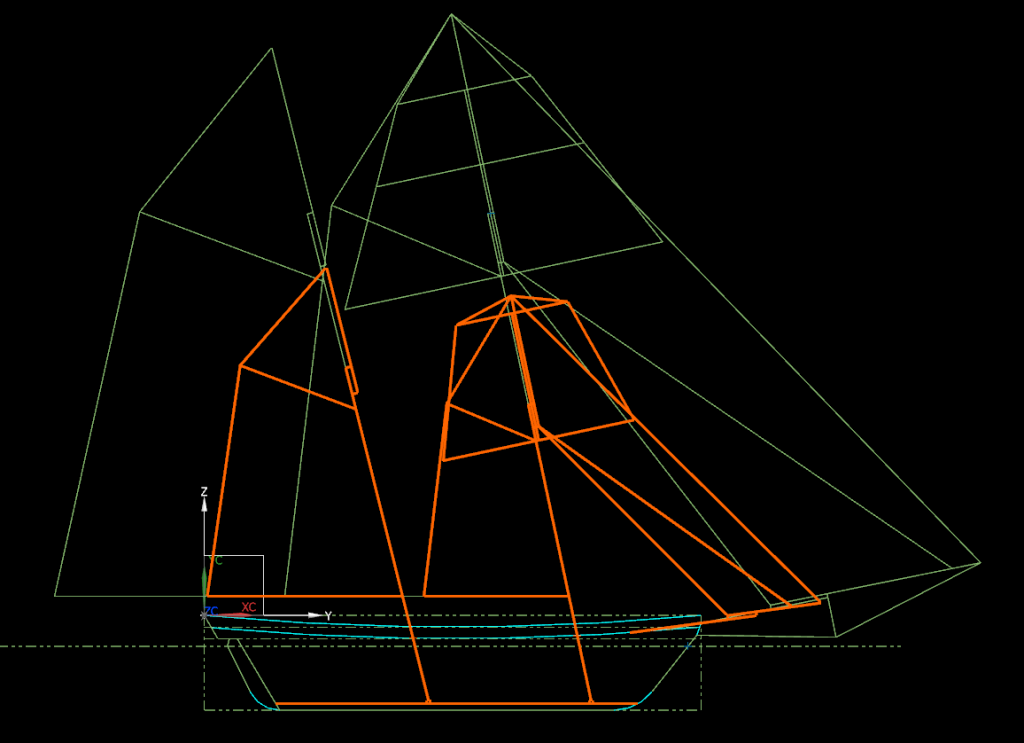
So, anyway, I decided to just take the average of all the values, draw it out and then adjust what doesn't look quite right. This rig below is the average mast and yard lengths:
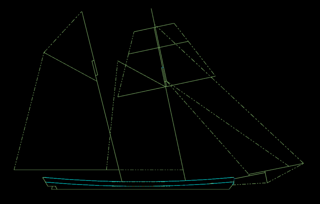
I cut the picture off at the waterline, since that's how Chapelle did it in all the other pictures on the book. Here is a collection of ones that I like:
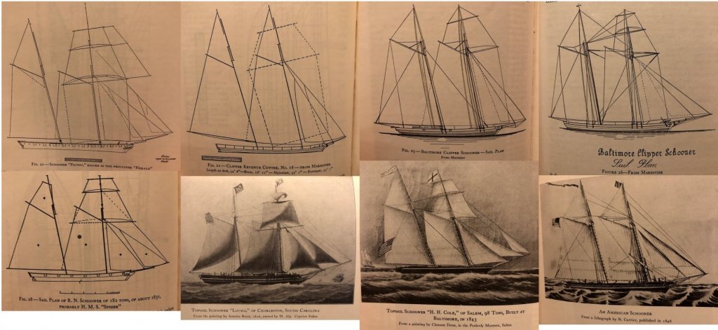
Looking at these, I think my square sail yards can be a bit longer. I think the main top mast can also be just a smidge longer. I'd like the bowsprit angle to be higher than shown, but that's pretty much determined by how it fits into the model itself. I'll have to see what, if anything, I can do there. Maybe cut off the bottom corner where it mounts to the deck, making it look like it passes through the deck. The rest of them look good to my eye. Maybe the gaffs can be a touch shorter.
What do you guys think?
-
That's a really good idea. I'll see if I can calculate the center of buoyancy, center of gravity and center of sail pressure. I have some formulae for that.
As to the particular ship, well, this is a banned kit. I bought it for my nephew but ended up starting it myself (he builds plastic car kits and my wife didn't think he'd be too impressed to get a box containing a few sheets of wood and one sheet of instructions). As far as I can tell it's a scaled down copy of the AL Harvey. I've looked at all the AL Harvey build logs on MSW, but I couldn't find any mast lengths or ratios anywhere, and I'm hesitant to scale off of photos. I'm not too concerned about being historically accurate; even my time period is loose - anywhere from 1800 to 1850 works for me.
So yeah, I'm using this build to learn as much as I can and then, after I finish it, I'll start a build that I can post a log of. Perhaps something like one of Chuck's kits for the barge, pinnace or longboat. In the meantime though, I'm still planning on doing my best on this one and not rush through it and neglect it.
But that's a really good idea. I think I'll have to take some measurements, loft a 3D hull in CAD and do some math. I know roughly what the ship is supposed to weigh, I can calculate mast and sail weights and there are formulae for center of pressure in the book. Or I can just take the average of the above values be done with it. It certainly sounds like that's what the original builders of the Baltimore Clippers did, just sort of look at other examples and copy some of the distinguishing features from memory. Which is pretty much how they ended up with such extreme rigs and hull shapes.
-
Right, so last night I redid my whole spreadsheet from scratch. I did this in three ways:
- I measured line drawings in Chapelle's book and calculated the ratios between the mast lengths and hull length/breadth for those drawings. I chose drawings that looked good to me. Then I used those ratios and applied them to my build to get the various mast and spar lengths. There quite a bit of variation.
- I used Fincham's tables at the back of the book, which gives ratios to extreme breadth and waterline, and calculated min and max values for each mast and spar.
- I used Rankine's ratios, which Chapelle says is based on Fincham's tables, to get min and max values for each mast and spar.
- There's also a bunch of ratios by Marestier, but I didn't have time to get to them, unfortunately.
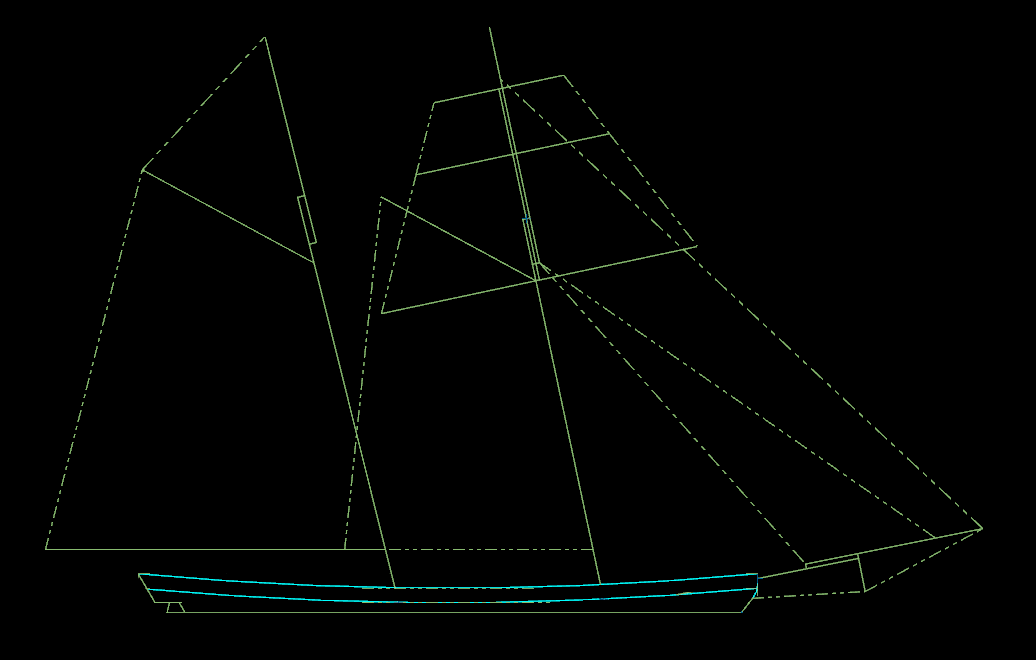
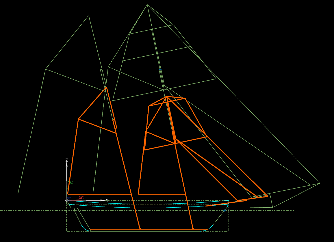
Then I tabulated all the values, calculated min and max values and drew them in CAD. There's a massive difference between the two sets.
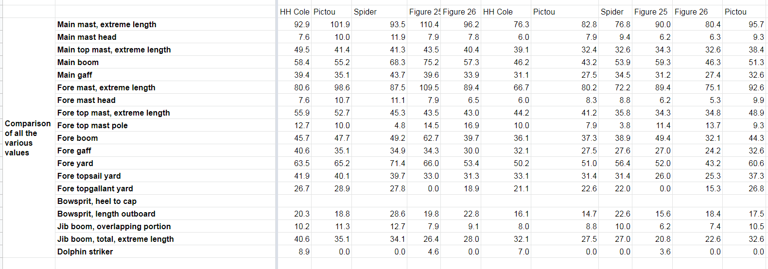
Below is my table showing all the values that I got off of the line drawings:
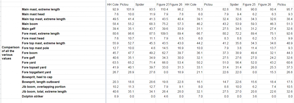
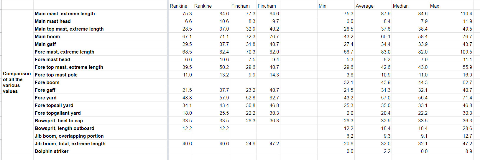
Below is my table showing the values for Rankine and Fincham, with the min and max values for all of them together:
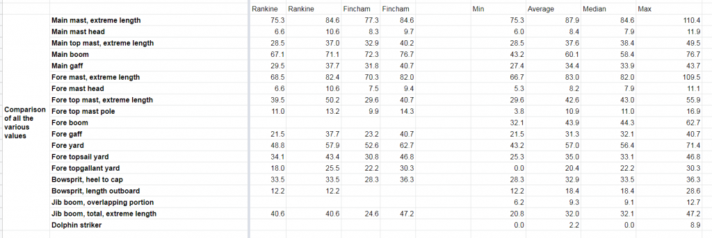
And here is the CAD sketch showing the minimum mast layout in orange and the maximum in green:
It looks to me like the Rankine and Fincham values are about the same as what I got from the drawings, if I just take the average of everything:
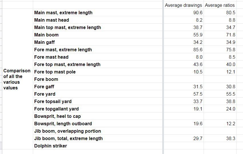
Should I just go ahead and use the average of all of these? Or maybe use the average and then tweak it in CAD (while staying well within the min and max limits) until I get a rig that looks good? Maybe make the masts slightly too long, to make it the schooner top-hampered, which was traditional.
-
Hahaha, awesome. Now I've confused someone else as well.
The extreme breadth is 32'. If I use the middle of the range, 2.7, then I get 86.4'. And then I rounded down to 86' for some reason.
The main-topmast, hounded is extreme breadth x 0.9 = 31' x 0.9 = 28.8'. Then the mainmast head is 28.8' x 0.3 = 8.6'
These aren't the number I had originally. And my spreadsheet isn't giving me the correct numbers. Looks like I got lost somewhere.
I think I'll start a new spreadsheet tonight, re-measure the model, do all the calcs from scratch, and redraw everything in CAD. Then I'll post what I have tomorrow morning.
- pontiachedmark, mtaylor and druxey
-
3
-
Hi Druxey,
Thanks for the (very quick) reply. So, just to make sure, the bottom is measured from the very bottom of the mast, where it forms a round tenon which pops into that little block on top of the keel?
So if the mast length works out to 86' and the mast head to 7'6", that means it's 86' from the very bottom of the mast to the bottom of the head, and then an extra 7'6" to the mast cap, which gives a total "timber" length of 93'6". Or is it 78'6" from the bottom of the mast to the bottom of the head and then another 7'6" to the mast cap, giving 86' overall?
-
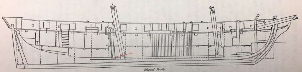
I have a stupid question. When mast lengths are specified, from where to where do they get measured?
From The Baltimore Clipper by Chapelle, he gives:
Mainmast, from heel to hound = extreme breadth x from 2.6 to 2.8
Heads of lower masts = topmasts x from 0.9 to 0.97
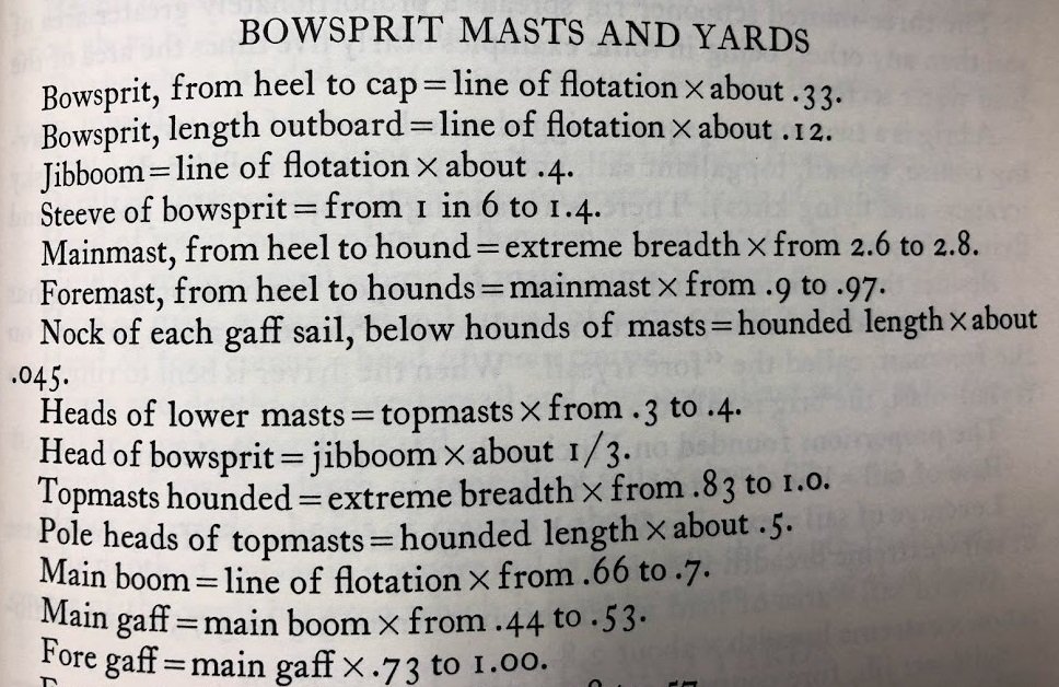
Now, I have the line of flotation (roughly) and the extreme breadth. But does the bottom measurement start right at the bottom of the mast, where it goes into it's support, right on the keel (marked A below)? Or does it start at the deck (marked B)?
Does the top measurement stop at the bottom of the head (C), or at the top of the head (D)?
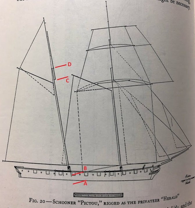
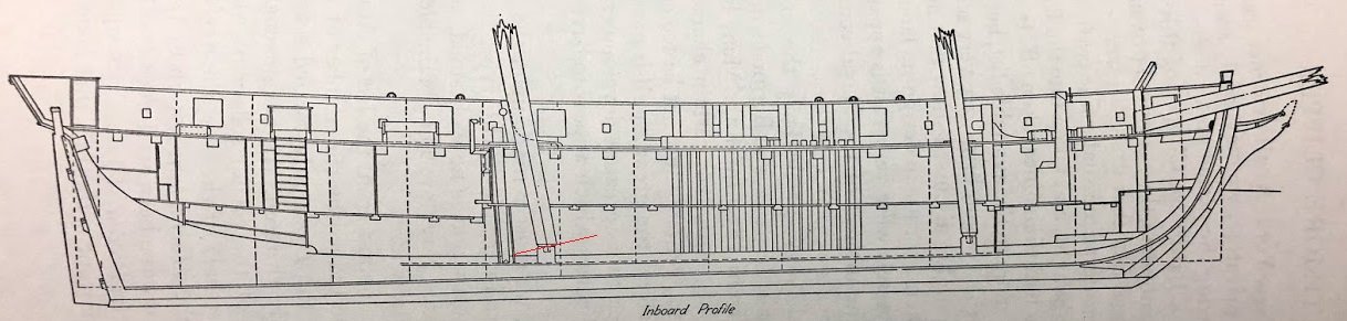
I do apologise for how simple this must seem to some of you, but this is my first build and I'm super confused. I'd appreciate any help or advice. When I draw it all out in CAD, the different versions of the measurements make a huge difference in what the rig looks like. Strangely, irrespective of where I choose to measure, I can't quite get the CAD drawing to look quite like the sail plans in the book. I'm tempted to just scale off of one the drawings that look good (like this one, of Pictou/Herald) and disregard the tables and formulae and ratios. I'm fairly certain that that way lies some gross errors though.


Queen Anne Barge by MEDDO - FINISHED - Syren - scale 1:24
in - Kit build logs for subjects built from 1501 - 1750
Posted
They say that you lose 50 IQ points as soon as you open a glue bottle. Been there, done that.