


iMustBeCrazy
-
Posts
958 -
Joined
-
Last visited
Content Type
Profiles
Forums
Gallery
Events
Posts posted by iMustBeCrazy
-
-
12 minutes ago, Greg Davis said:
Could that be fuel and the double cone on top just coolant?
On the 20, yes (brain fade) the big one behind the pilot seat is fuel.
But on the 19 there should be no coolant so it looks like he's using the fuel tank as an oil cooler or he's using the oil to heat the fuel (the oil tank in front of the engine would also act as an oil cooler).
The piping appears to pass through the fuel tank.

I don't know if there was a problem with something like wax in early fuels but I can't imagine why you would heat your fuel to the point it starts boiling off. 😟
On the 20, you're right, it's a coolant header tank. I assume it's unpressurised so the 'conning tower' out the top is to allow steam to condense and/or water to settle or perhaps not slop out when turning?

- Canute, yvesvidal and Greg Davis
-
 3
3
-
Alberto must have owned a worm cannery, there are more worms here than in Bounty's small cutter.
1 hour ago, Greg Davis said:I guess one would need to be reversed to accept fuel from the tank funnel that is between the two carburetors on Santos-Dumont's No 18 set-up.
No worms here, just run the fuel line to a 'T' and from that to each carb, no need to turn anything around.
On to the worms.
I was going to say you were lucky as on the Demoiselle the carburettor was under the wing wrapped in a piece of cloth which means I can't see it to draw it.
When looking for a photo I realised that was on the 19 not the 20 I'm doing.
Then I noticed the fuel tank with the associated plumbing, can of worms number one, this engine is air cooled, what's the plumbing for? The oil tank looks to be at the front of the engine.
On the 20, the plumbing to the fuel tank is definitely coolant (it comes from the water jackets around the cylinders) which opens can of worms number two, why would you heat the fuel to above it's boiling point?
Problems raised (for me) neither the coolant hose from the tank (there must be one, right?) or the carburettor (of the 20) are shown in any photos.

-
1 hour ago, Greg Davis said:
Also, quite a different air intake than the 'spider' version!
Well this version is fuel injected and has no way of controlling the amount of air ingested. The fuel injection pump timing adjustment (both coarse and fine) is interesting and the untimed pump will be oil. The water pump is hiding in the housing below and all three in this case are gear driven.
As far as I can see Alberto didn't use fuel injection so yours should have a couple of carburettors, but I suspect you don't have any space left.
- Greg Davis and Canute
-
2
-
- Canute, Greg Davis and AON
-
2
-
 1
1
-
-
2 hours ago, oakheart said:
Might even do a painted base.
You can try sitting her on coloured paper to get a feel for how it looks.
If you go high gloss it's going to have to be perfect, if you go satin finish it will be more forgiving.
That said, I'd probably try a gloss black.
Another option might be a diorama type sea (just the top of the plinth) with her floating above.
-
1 hour ago, oakheart said:
Comments please.
That's a tough question Tim, it all comes down to taste but it sounds like you're not convinced.
Myself, I feel that there's too much wood and too much straight grain. I think a black marble (or faux black marble) would add elegance and contrast.
Otherwise a heavily figured wood, something complex and contrasty.
My tuppence anyway.
-
1 hour ago, Billpitts said:
Were there mostly cutters
Bill, Cutters were traditionally of clinker (or lapstrake) construction.
The launches, long boats, barges, pinnaces, and
yawls, are carvel-built; and cutters, jolly boats, galleys,
gigs, and life boats, are clincher-built.Also
Cutters of a Ship, (bateaux, Fr.) are broader, deeper, and shorter than
the barges and pinnaces-, they are fitter for sailing, and are commonly
employed in carrying stores, provisions, passengers, etc. to and from the ship.
In the structure of this sort of boats, the lower edge of every plank in
the side over-lays the upper-edge of the plank below, which is called by
ship-wrights clinch-work.Yawls, (canots, Fr.) are something less than cutters, nearly of the same
form, and used for similar services ; they are generally rowed with six
oars. -
A bit more, oil separator plugs and leads:
And a comparison with a real (later?) one:
- thibaultron, GrandpaPhil and Mike Y
-
2
-
 1
1
-
2 hours ago, Greg Davis said:
Today I felt the need to make something and take a break from understanding how Antoinette engines work.
I don't blame you. I've spent about eight hours trying to draw a plug lead. 🤬
- Greg Davis and Canute
-
1
-
1
-
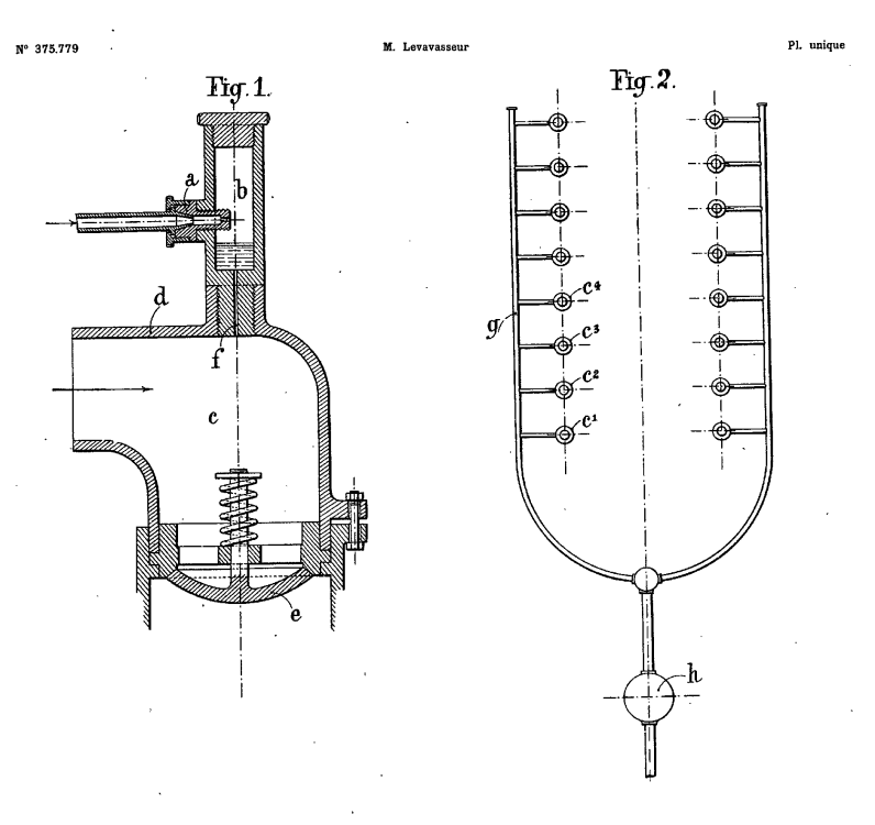
Ok, lets try this again:
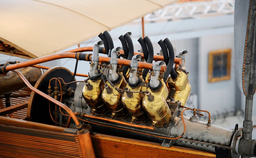
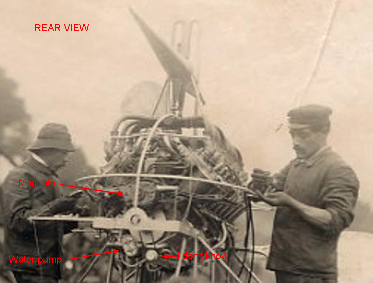
In this photo we see lots of oil pipes, we see the oil pump (or is that pumps?) at the rear of the engine with pipes coming out the top and bottom, we see an oil line running under and going into the front of the engine and into the prop shaft.
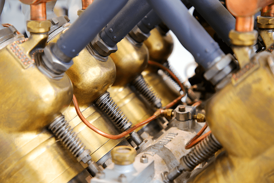
In this photo we see a crankcase vent (fuzzy closest to the camera) and a junction block (mid engine) connecting a fuel line, coming from the rear of the engine, with the fuel lines going to the cylinders.
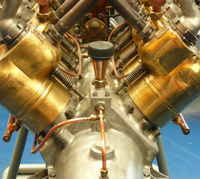
This photo showing the crankcase vent tied it all together.
This photo shows the oil pump (rear right, note the wide belt) better and a water pump (front right).
EDIT: I think it shows the oil pump and fuel pump (together) and the water pump.
- Canute, Greg Davis, ccoyle and 1 other
-
4
-
13 minutes ago, Greg Davis said:
made it appear the coolant pipes go below that long tube
You can see that in the shot above.
I think William nailed it.
Now, the only other shot of the tube I can find appears to have a narrower tube coming out the front then up.
Tilting the head to the left when viewing helps.
- GrandpaPhil, Canute, Keith Black and 1 other
-
4
-
10 minutes ago, Greg Davis said:
The engine that you are examining here looks different to me, in how fuel is delivered. I was under the assumption that there were two carbonators on the No18's engine that were fed by the rear portion of the conical tank. I thought the air/fuel mixture was then delivered through the spider-shaped manifolds. The engine you are showing here appears to have air intakes for each cylinder with fuel being injected separately.
I certainly can't say for certain, they could have changed anything.
The engine was designed with 'fuel injection' I put that in quotes as it was a continuous spray system spraying all cylinders at once, when the inlet valves were sucked open fuel and air were drawn in. I assume throttle was by controlling the amount of air.
- Greg Davis, Keith Black and Canute
-
3
-
7 minutes ago, Greg Davis said:
now that the thought is that the conical tank has fuel in the back and coolant in the front
Not by me, I'm certain that it's two tanks with the coolant to port of the fuel tank. It has a conical bottom like the fuel tank and is probably 'tear drop' shaped (like an aluminium mast). It shares the fuel tank mount.
Meanwhile I've found a new puzzle.
-
3 hours ago, Greg Davis said:
I didn't see how the top pulley
I'm not sure but I think what you're seeing might be the body of the device, it's really hard to tell.
Anyway, I can't find a definite oil pump on any of the Antoinette engine images, it is probably internal.See post 241.
The pic above I interpret Lets start from scratch, there is a journal (a path for fluid) through the block running the length of the engine above the camshaft.It is always seen with a copper pipe attached. This would have to be for fuel or oil. I now believe fuel. Near the connection there is an aluminium blockwith a brass 'nut', I think this is a regulator. In the above pic the pipes also go to the dash, I'm guessing to a priming pump so as to get fuel to the cylindersbefore the fuel pump is turning. This is still common in aircraft.
There is a tap into the journal mid engine (V8) with lines going (apparently) to the injectors. Which again suggests fuel.Why am I bringing this up? Well with the magneto on the aft end of the engine there is no room to get pipe into the journal at that end so either all the fuel plumbing is external or the fuel now goes in the front and perhaps the fuel pump is there too. But then what is the belt driven device aft?- Canute, Greg Davis and Keith Black
-
1
-
 2
2
-
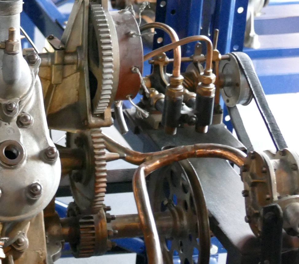
9 minutes ago, Greg Davis said:
Are you suggesting that the smaller pinion gear is still behind ?
I thought so but boy do I have a curved ball for you, what if they turned the whole engine around? It was designed to be able to be run backwards.
Lets ignore that for the moment and stick with what we know.
On the aft end we have a magneto, a water pump and another belt driven device (probably a fuel pump but we don't know).
The magneto must be gear driven using the same (type and size) gears as the camshaft.
On the forward end we have a possible pulley (?) driving possibly another pulley (??) driving another device. We cannot see crank or camshaft gears but they may still be there.
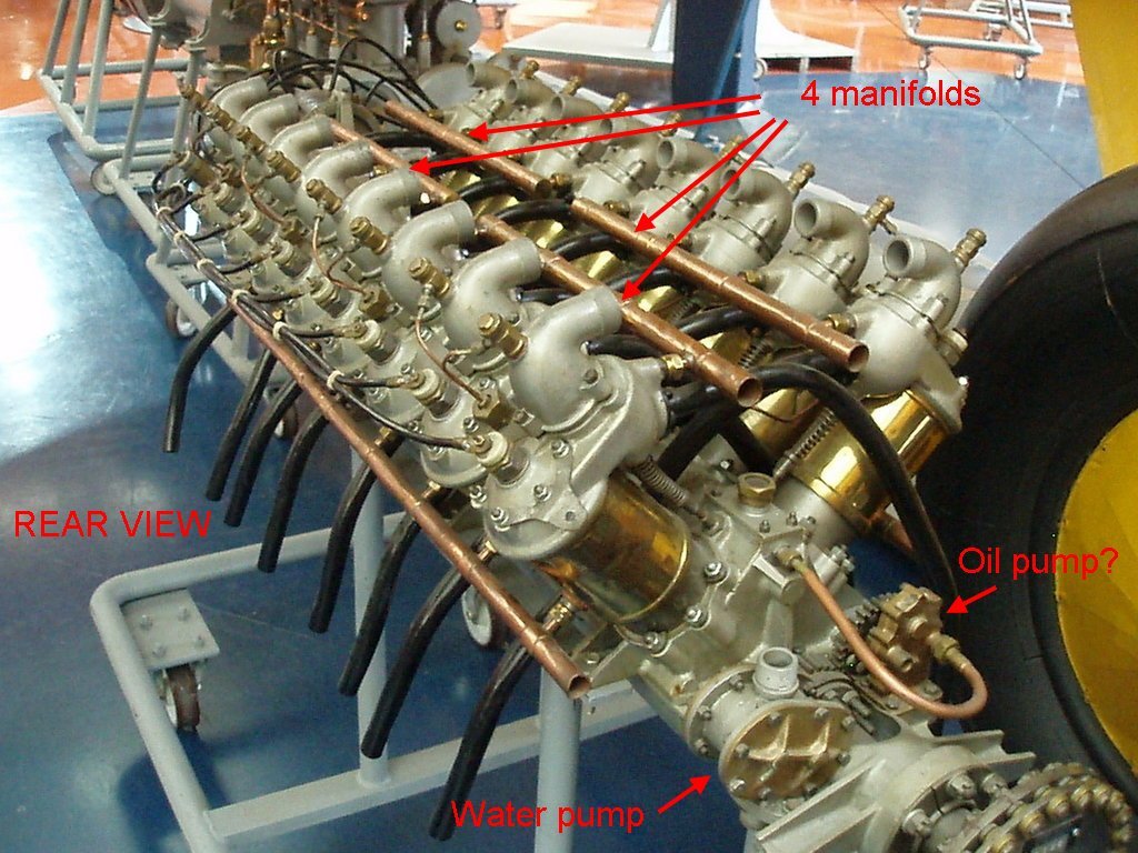
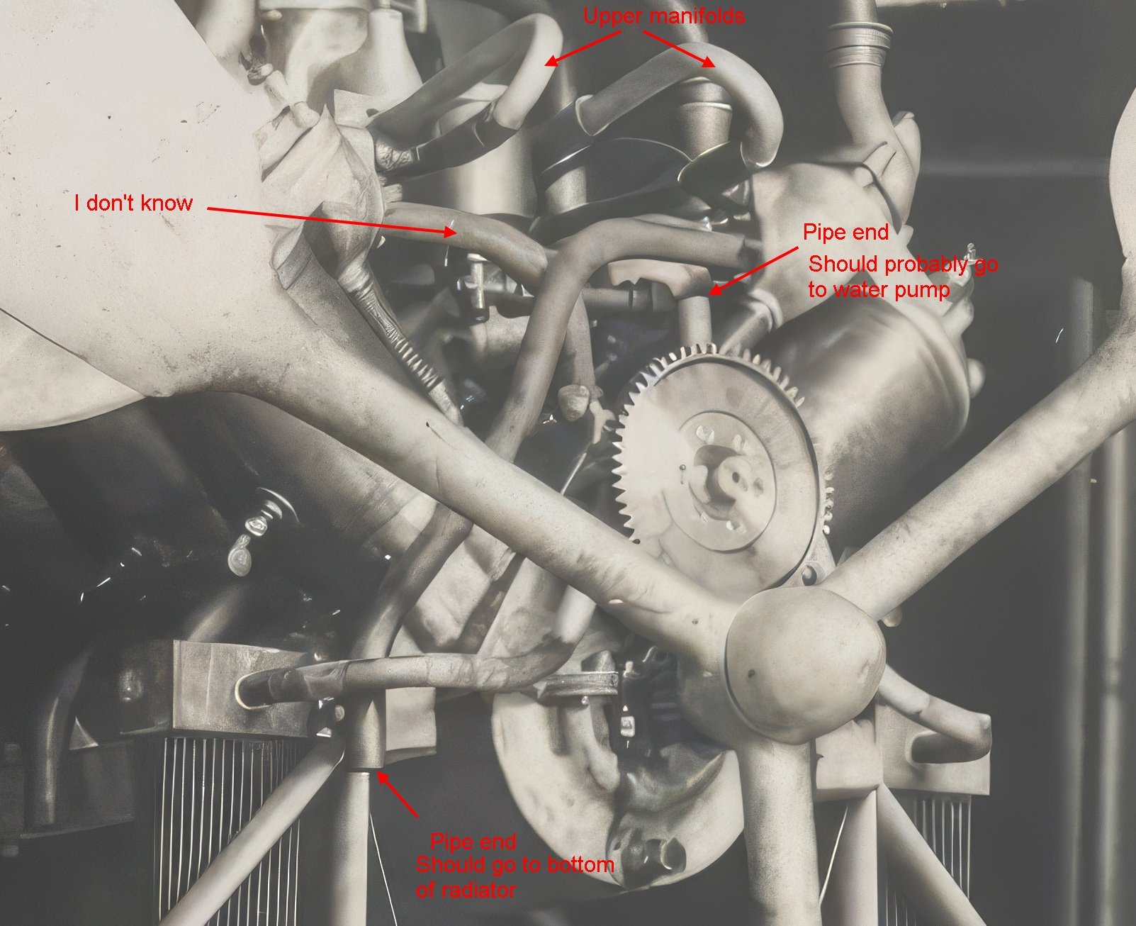
Coolant (most likely) comes down from the header tank into the 'Y' manifold, into the top of both radiators, out the bottom of the radiators to another 'Y' manifold, along the hull to the back of the engine and up to the water pump, out both sides of the water pump to the lower cylinder manifolds, out the upper cylinder manifolds to two 'T' joints (a guess) and back to the header tank via the two bent pipes.
- Keith Black, Canute and Greg Davis
-
3
-
13 minutes ago, Keith Black said:
If the engine was thermosiphon cooled
Keith, these are crops from pics in post 221.
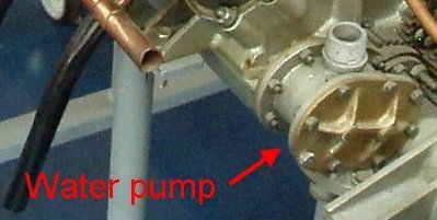 I think it's fairly obvious from the outlet that this is a water pump, not fuel or oil.
 And the double cross pattern here is the same but it has been rotated so the outlets are horizontal.
- GrandpaPhil, Greg Davis, Keith Black and 1 other
-
4
-
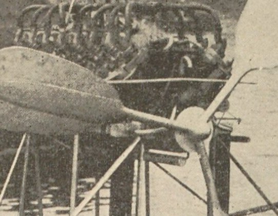
4 hours ago, Greg Davis said:
I don't understand the gearing by the propeller. I believe the engine was a 2-stroke, so the gearing between the drive shaft and the cam shaft should be 1:1. Is the camshaft driven in the rear with a gear between the magneto and the engine? The gearing in the front of the No17 setup looks closer to 3:1 and then maybe reversed to 1:3 later.
Now, bear with me I've just woken up so I might get some of this wrong.
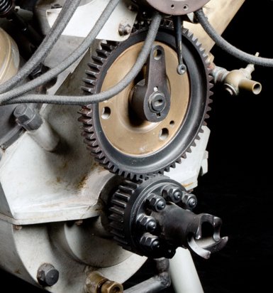
The prop, I think, is driven directly off the crankshaft. The gear on the crankshaft has 32 teeth, the gear on the camshaft has 64 so the ratio is 2:1. It's a four stroke.
It's easier to see in this V8 pic (and you can count a quarter of the teeth on the v16 and get the same result):
Then I found this:
The Antoinette engines used a primitive type of direct fuel injection. A belt-driven fuel pump at the rear of the engine fed fuel into a small reservoir (injector) located above each intake valve.
So it needs a fuel pump as well as an oil pump and a water pump. Or is my 'oil pump' a fuel pump,
I still need to check but I don't think soyes it probably is.- GrandpaPhil, Greg Davis, Keith Black and 1 other
-
4
-
28 minutes ago, Greg Davis said:
are exhaust pipes!
Doh!
- GrandpaPhil, Keith Black and Canute
-
3
-
3 minutes ago, Keith Black said:
is the large gear driven off the prop shat the timing gear driving the camshaft?
Yes.
- Canute, Greg Davis and Keith Black
-
2
-
1
-
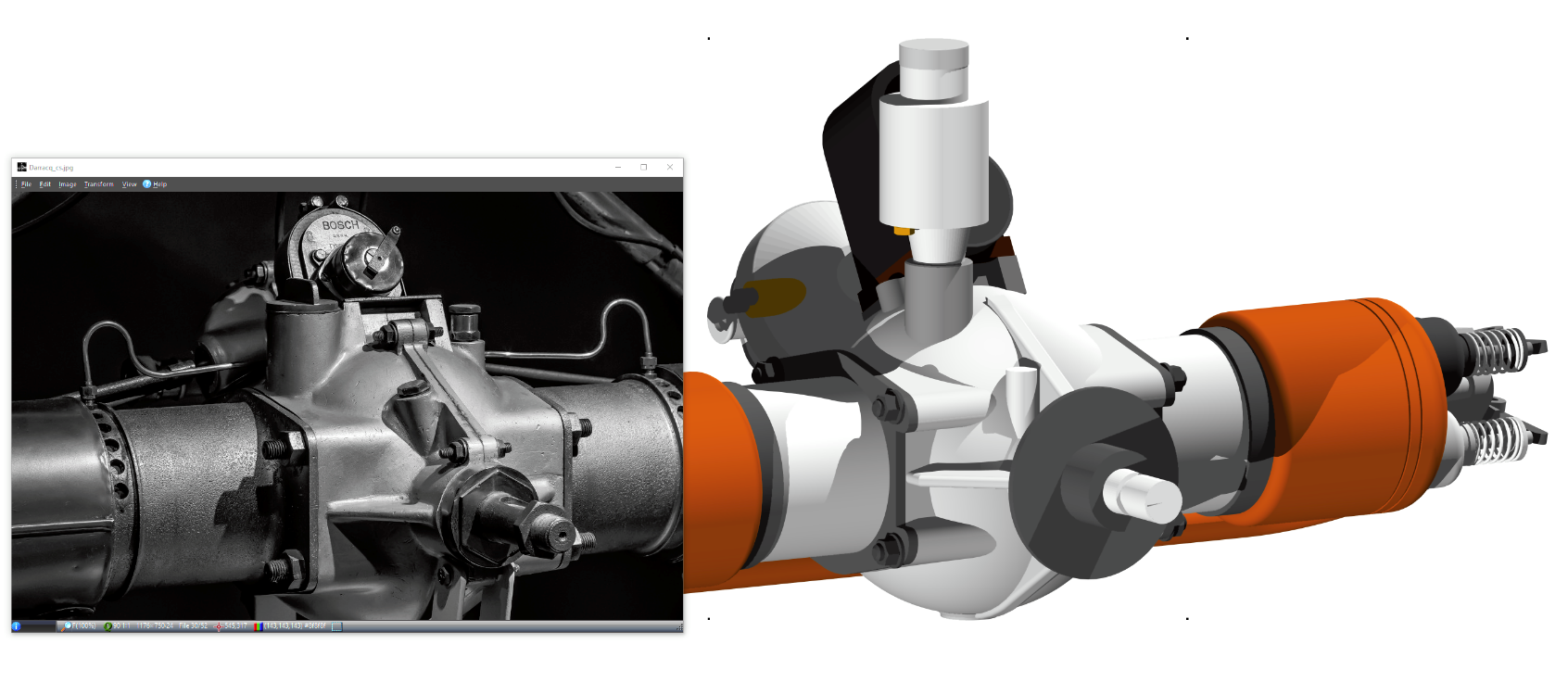
Ok, I think this nails the water pump.
The "I don't know" may be a booster pump given the extent of the plumbing and the height of the header tank. Maybe.
The ?? (post 215) may be a gear driven oil pump moved to the front. Just a guess.
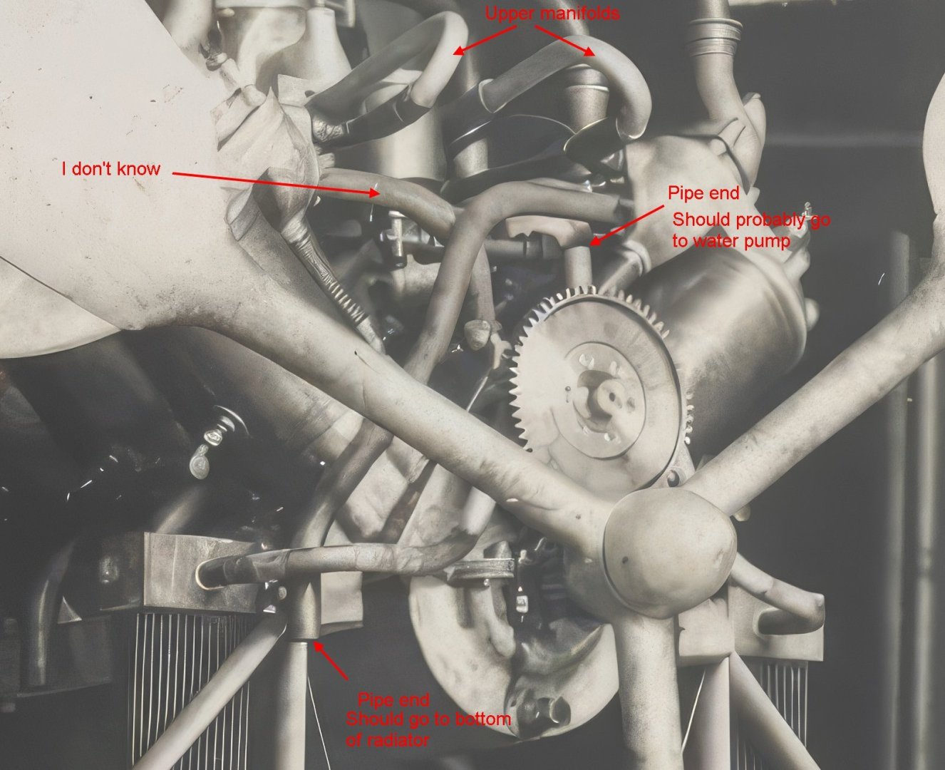
The top pipe from the radiator 'Y" manifold could go to the water pump or the lower cylinder manifolds. In the top pic it looks like the water pump feeds the lower cylinder manifolds.
EDIT: Sounds like I mostly agree with William.
- Canute, Keith Black, GrandpaPhil and 2 others
-
4
-
1
-
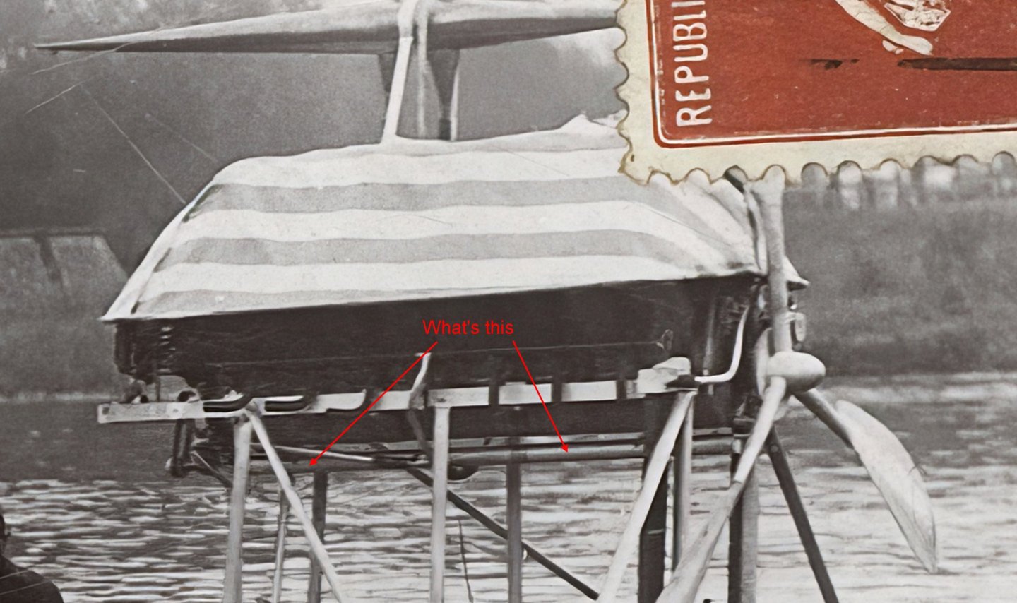
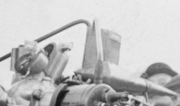
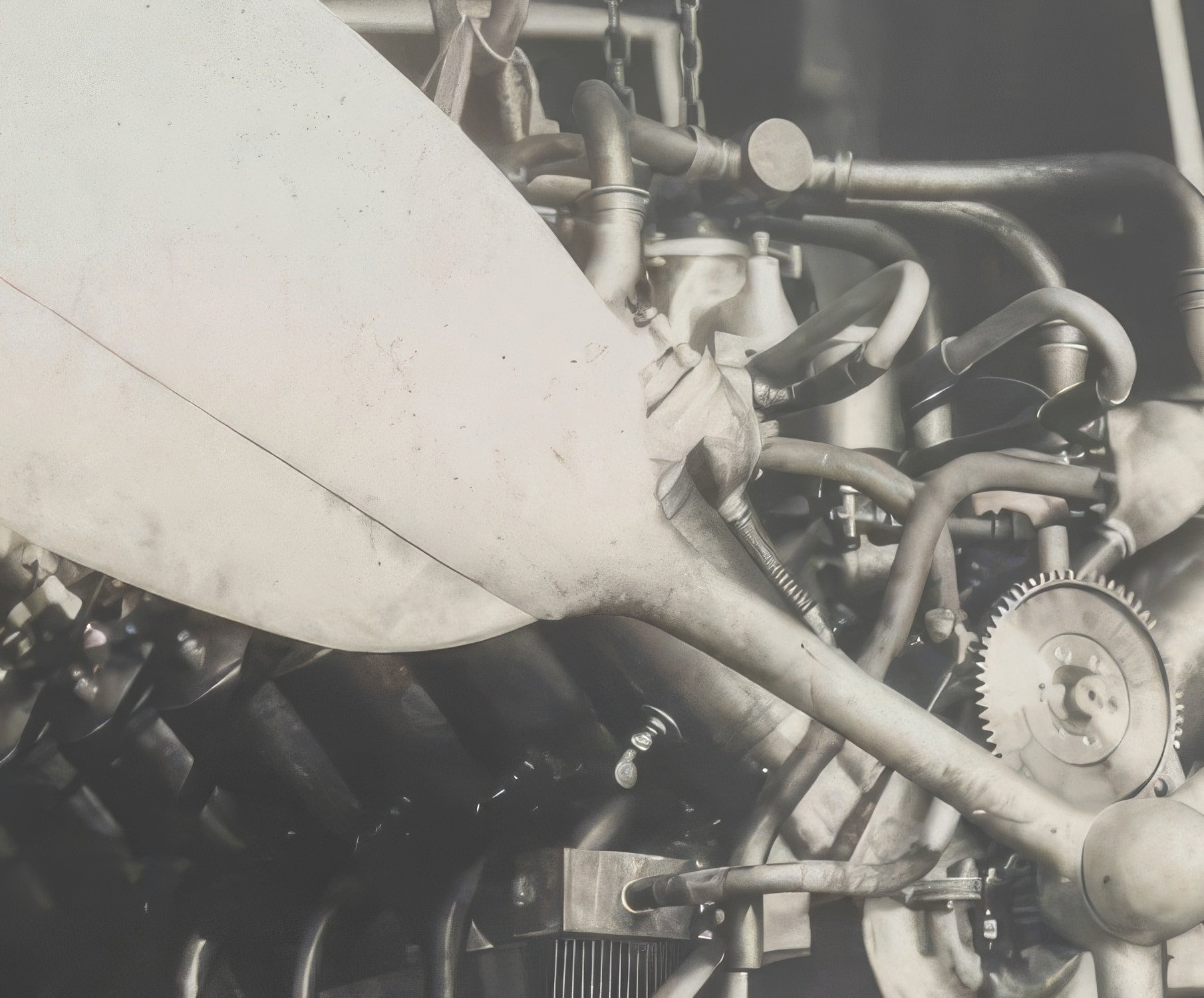
11 minutes ago, Greg Davis said:
Today, while looking at the photo you last attached, it actually appears that there may be two belts / pulleys - one vertical that would operate the water pump, and one off to the right (in the picture) with another (unknown) function:
The red arrow is pointing to the camshaft drive gear, note that the pipes to the radiator join behind it and go up then bend back to run along the top of the block.

- AON, Canute, Greg Davis and 2 others
-
5
-
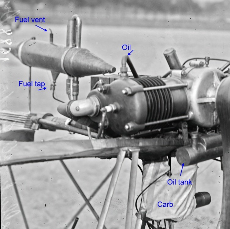
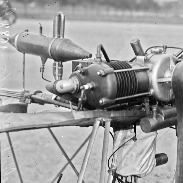
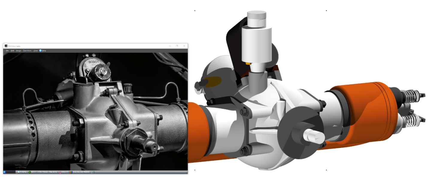
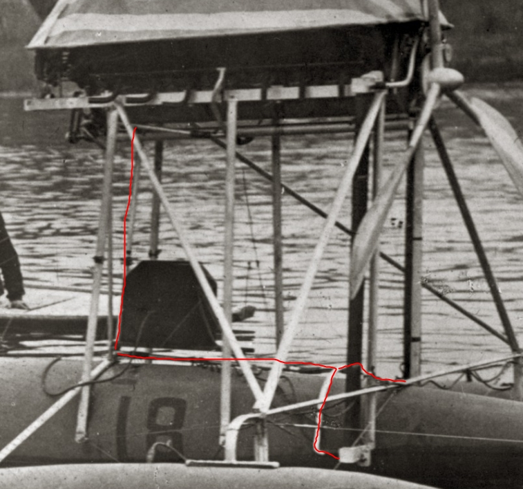
17 minutes ago, Greg Davis said:
Do you know the purpose of the tubes
Greg, The Demoiselle had a coolant header tank there so I suspect that's it.
So, from the header tank through the radiators to the water pump through the lower manifold through the cylinder jackets to the upper manifold and back to the header tank.
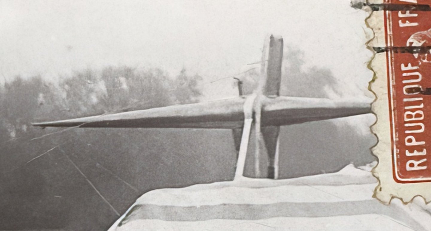
Demoiselle below.
- Keith Black, GrandpaPhil, AON and 1 other
-
4
-
On 4/12/2025 at 6:39 AM, Greg Davis said:
In the later (final?) set-up, it appears that the water pump is run off a belt drive from a larger pulley mounted to the propeller shaft.
I've been trying to nut out what's going on up front, and failed.
Having the water pump aft was normal on the V8 and having the magneto aft helps keep it out of the spray. But what ? and ?? are I have no idea.
There's not much space for ? to be a pulley and ?? could be gear driven so why would you need a pulley?????


Mucking about in 3D - Again - Santos-Dumont Demoiselle
in CAD and 3D Modelling/Drafting Plans with Software
Posted
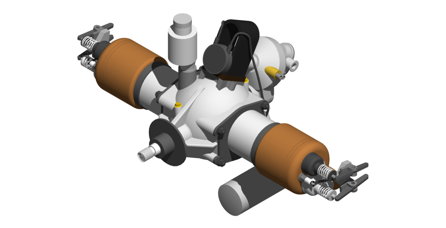
Not much to show this time, just push rods and a bit of tidying up.
I got distracted trying to draw a prop for it and that's proved to be problematic, I see a way forward but it's going to be a pain.
Still outstanding on the engine are a carburettor, oil lines, cooling system and extra flanges and bolts.