


iMustBeCrazy
-
Posts
958 -
Joined
-
Last visited
Content Type
Profiles
Forums
Gallery
Events
Posts posted by iMustBeCrazy
-
-
39 minutes ago, oakheart said:
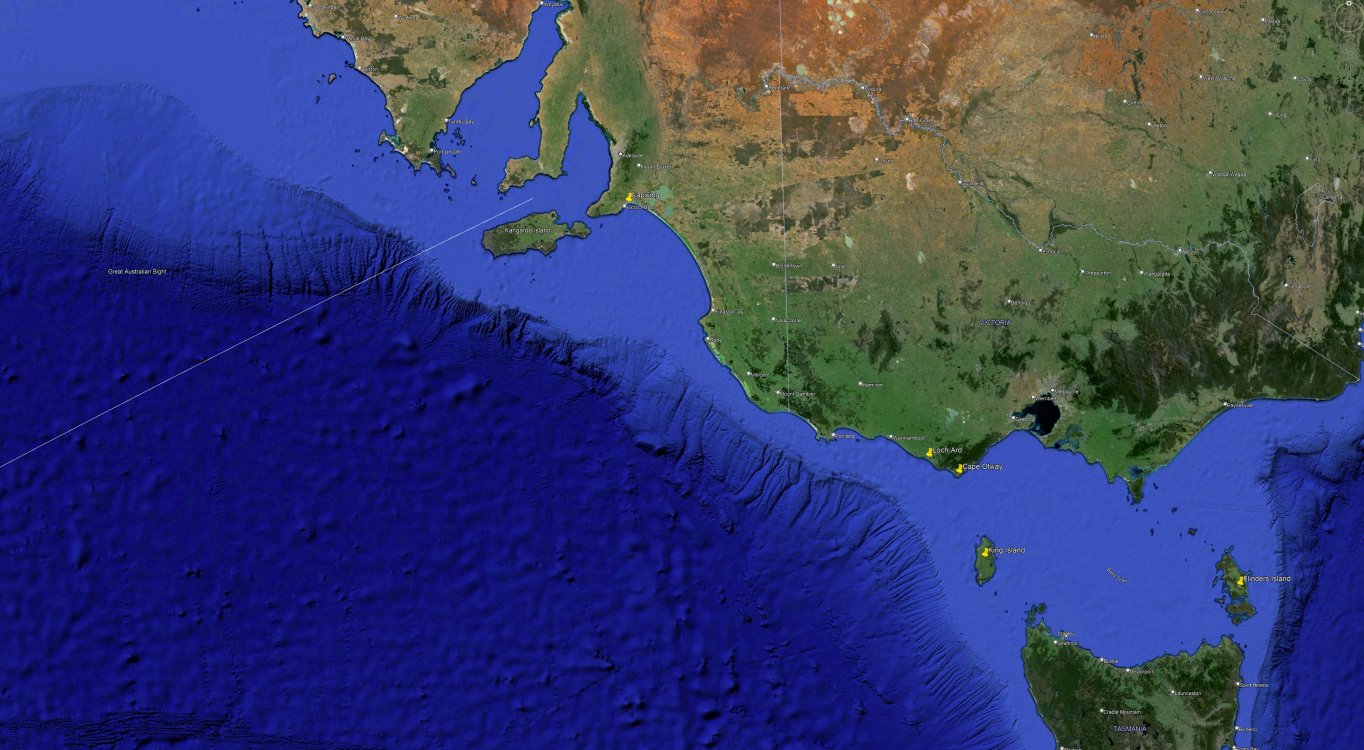
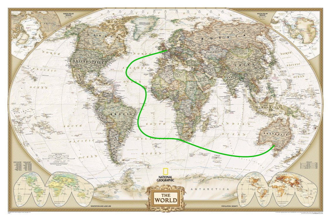
In their dash to reach the Victorian goldfields in the quickest possible time, many ship's captains adopted the new 'Great Circle' route in the 1850s. Passing far south of the Cape of Good Hope, they sought the 'Roaring Forties' – the strong prevailing winds that blew from the west to the east between 40 and 50 degrees south.
This route involved enormous risks from drifting icebergs and the wild seas generated by frequent storms. It required exceptional navigational skills, as even the slightest error could lead to disaster. The large number of ships that were lost when navigating the narrow path between King Island and southern Victoria led to the West Coast of Victoria becoming known as the Shipwreck Coast.
The Roaring Forties was only the start, you could try your luck further south in the Raging Fifties or even the Screaming Sixties. Along the edge of the Roaring Forties was pretty much the standard route.
Fortunately for those aboard Lapwing she turned north to Adelaide long before reaching King Island or Victoria's south coast.
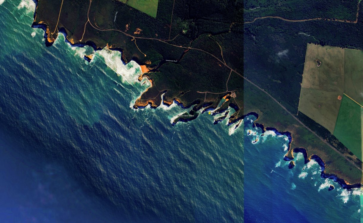
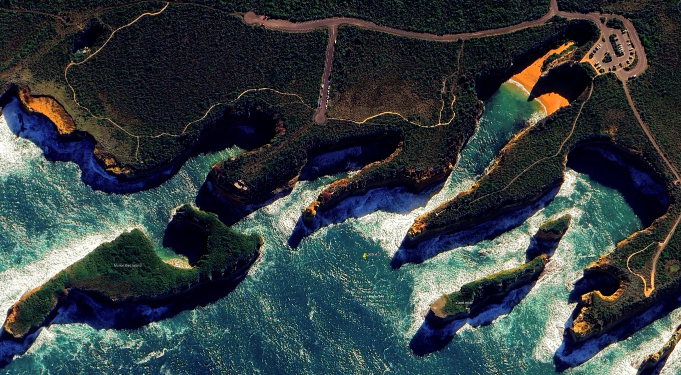
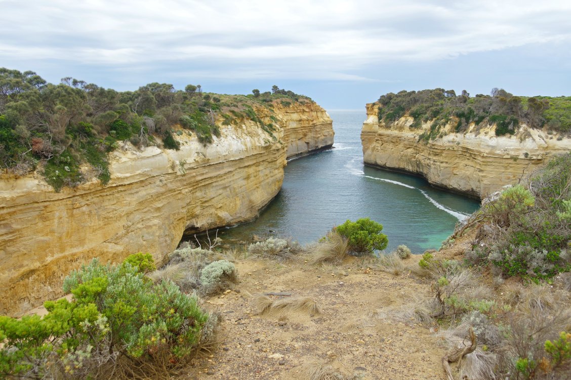
The Loch Ard is well remembered, the gorge she foundered off is name after her (it's the one with the big car park).

- CiscoH, GrandpaPhil, mtaylor and 1 other
-
 4
4
-
14 minutes ago, oakheart said:
From what I remember you saying they had loads of other people as passengers, how did they manage on the very long journey?
They finished up with only one paying passenger plus the owners family (wife and two daughters) and two servants (this is from newspaper articles and the servants may actually have been the daughters). They were heading out for the Gold Rush so possibly had a full (free?) crew.
32 minutes ago, oakheart said:Do you know which route they took?
I don't actually have any info from my Great grandfather but again from newspaper reports (passing ships took mail and messages and reported sightings, whoever reached port first let them know who was coming and vaguely when to expect them) it was London to Cape Verde then probably Cape Town via the Brazilian coast, then on to Adelaide or Adelaide direct (I think Cape Town). Roughly 14,500 nautical miles in a boat that fits comfortably in my cousins front yard ( a 1 acre block, ~100' wide).
 31 minutes ago, oakheart said:
Was the weather with them or did they have bad storms?
No idea but probably.
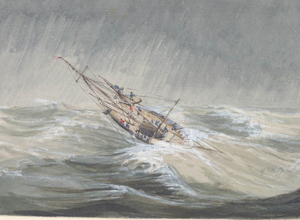
50 minutes ago, oakheart said:I remember seeing film of a sailing ship going round the 'Horn' it was a not a comfortable thing to do.
Supposedly Bramble just going in to Brisbane:
- mtaylor, GrandpaPhil, oakheart and 1 other
-
4
-
-
22 hours ago, oakheart said:
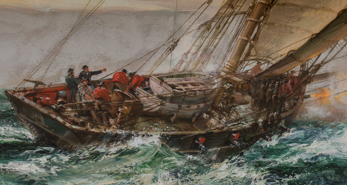
the problem is I wanted to make the model look like the painting which just grabbed me as an exciting image.
Yes it's an exciting image, probably more so for me as I can (and did this morning) visualise my Great grandfather on board.
I don't remember why I thought she was the 1778 Kite, perhaps I mixed up dates in my head, but that extra row of planking above the gun ports makes her more likely to be post the very early 1800s. Given the painting is dates ca1850 it is possible the artist as a boy knew Lapwings sister and remembered her fondly. There are discrepancies, the companionway faces aft and the wc and pantry are missing but she carries the right number of guns (well gun ports, she probably didn't carry a full compliment of guns) in the right places. He may have used Lapwing as a model as she was still around at the time of the painting but made changes based on boyhood memories, who knows.
Looking at the painting itself, she's running downwind with both the main and square sail set, that would be wrong, she would be unbalanced with the main trying to turn her to port. Look at the helmsman, he's heaving on the tiller trying to keep her on course. The artist understands, this is a chase, every fraction of a knot counts. As you said, an exciting picture.
So, yes this could be Lapwings sister, Speedys aunt.
-
21 minutes ago, oakheart said:
I also realised that when I add the skylights to the deck, the boat will need to sit much higher off the deck, I will have to revise the cradle.
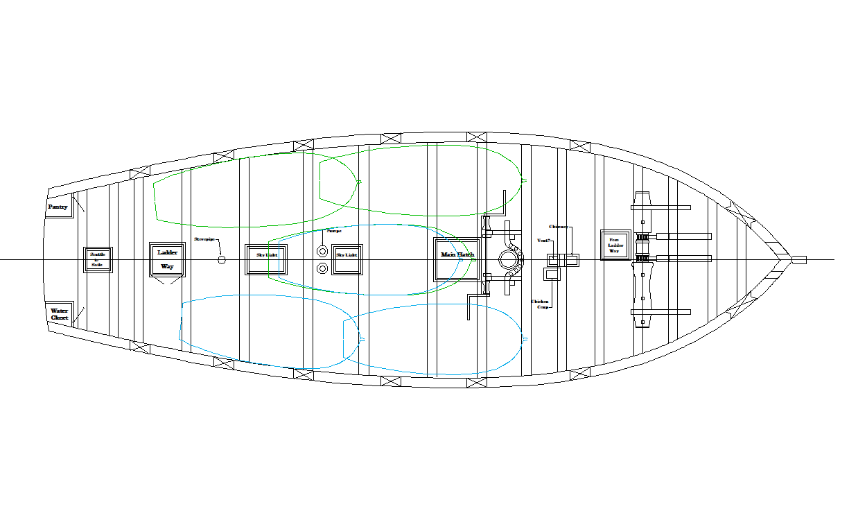
Tim, don't forget the pumps.
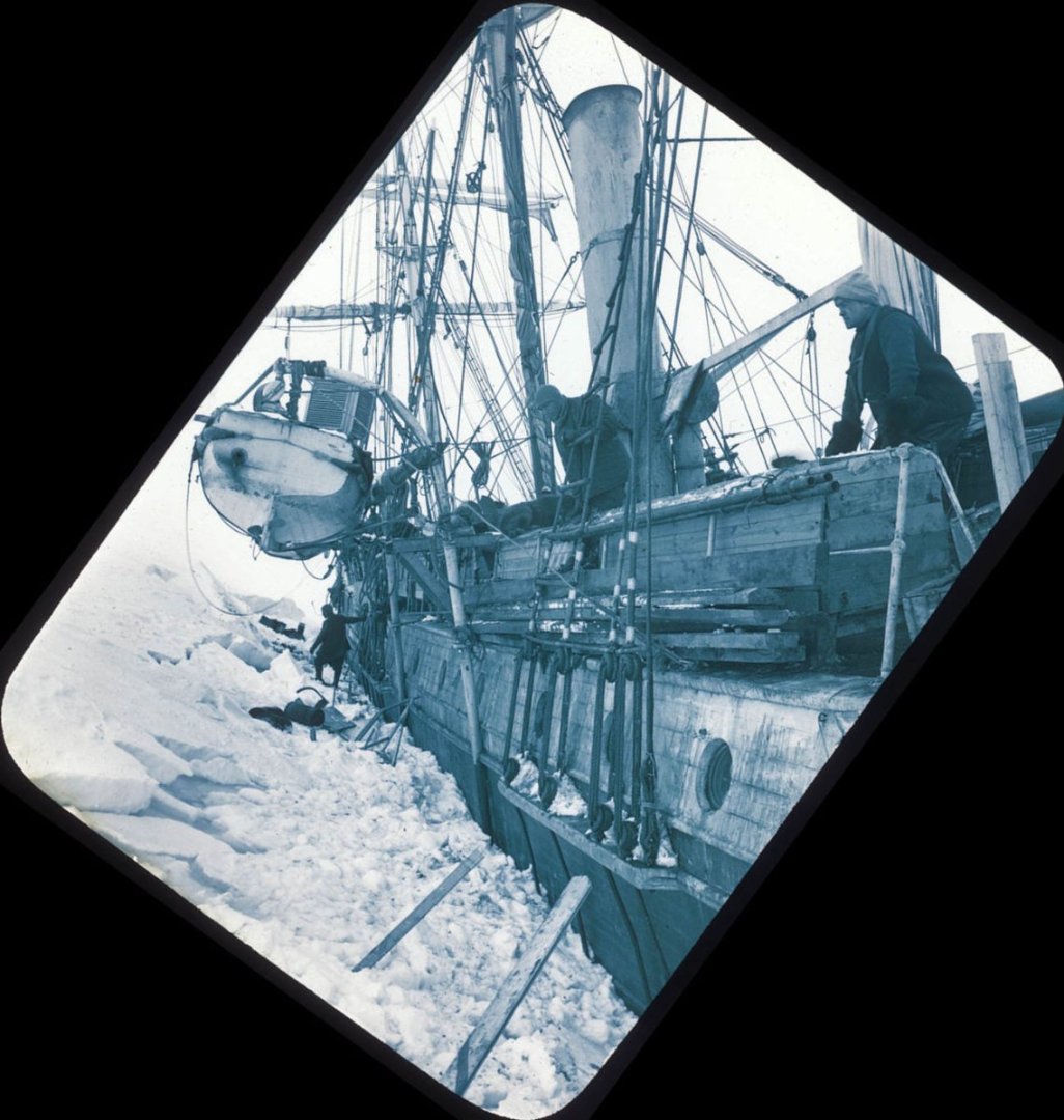
I had a little play with ideas when you first posted your little cutters little cutter. I came up with ZAZ6347 (Vigilant) which has light pencil lines representing boats each side of the main hatch. Now Vigilant was a little larger making this more practical but I drew 18' (port) and 16' (stb) cutters on Lapwing:
-
-
On 4/9/2024 at 3:59 AM, theoracle09 said:
The port side is odd, the sides extend well passed the mizzen deck.
1 hour ago, Tomculb said:I too pondered over the photo you posted and decided that the port ladder was probably a portable one they moved around from place to place.
As they decked over the bridge deck openings the four forward ladders became redundant. It would appear one was cut down and used to get over the top of the kennels, another had a couple of upper treads removed and used port side aft probably because the amount of stores along the centreline prevented previous access from the starboard ladder unless you went all the way up to the mainmast and back. Just a guess.
- Tomculb and theoracle09
-
2
-
-
2 hours ago, theoracle09 said:
I believe the cook to be standing on the port side
Correct, outside the galley door.
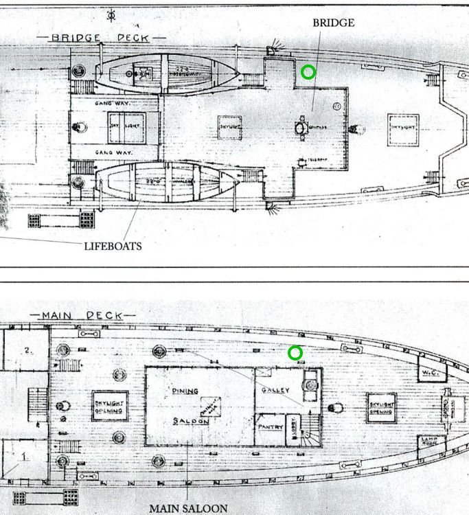 2 hours ago, theoracle09 said:
However, this looks more to me like the port side mizzen lower deadeyes
Again correct.
- BobG, theoracle09, Keith Black and 1 other
-
4
-
On 3/27/2024 at 5:22 AM, Sanjith_D said:
so I would like to hear your guy’s experiences with whether something like this Would work. I'd also love any tips for any aspect of this project, especially transcribing the Frigate's plan into CAD
Well, you can follow my bumbling path through the links in my sig with the Lapwing drawings and build (to date) but I seriously suggest you start with something simpler than a Frigate, say a dinghy, skiff, dory etc. in 1:24 or 1:16
Meanwhile look for Frigate drawings you like in the best quality you can find, perhaps the Enterprize class, many nice big drawings:
-
1 hour ago, Mike Shea said:
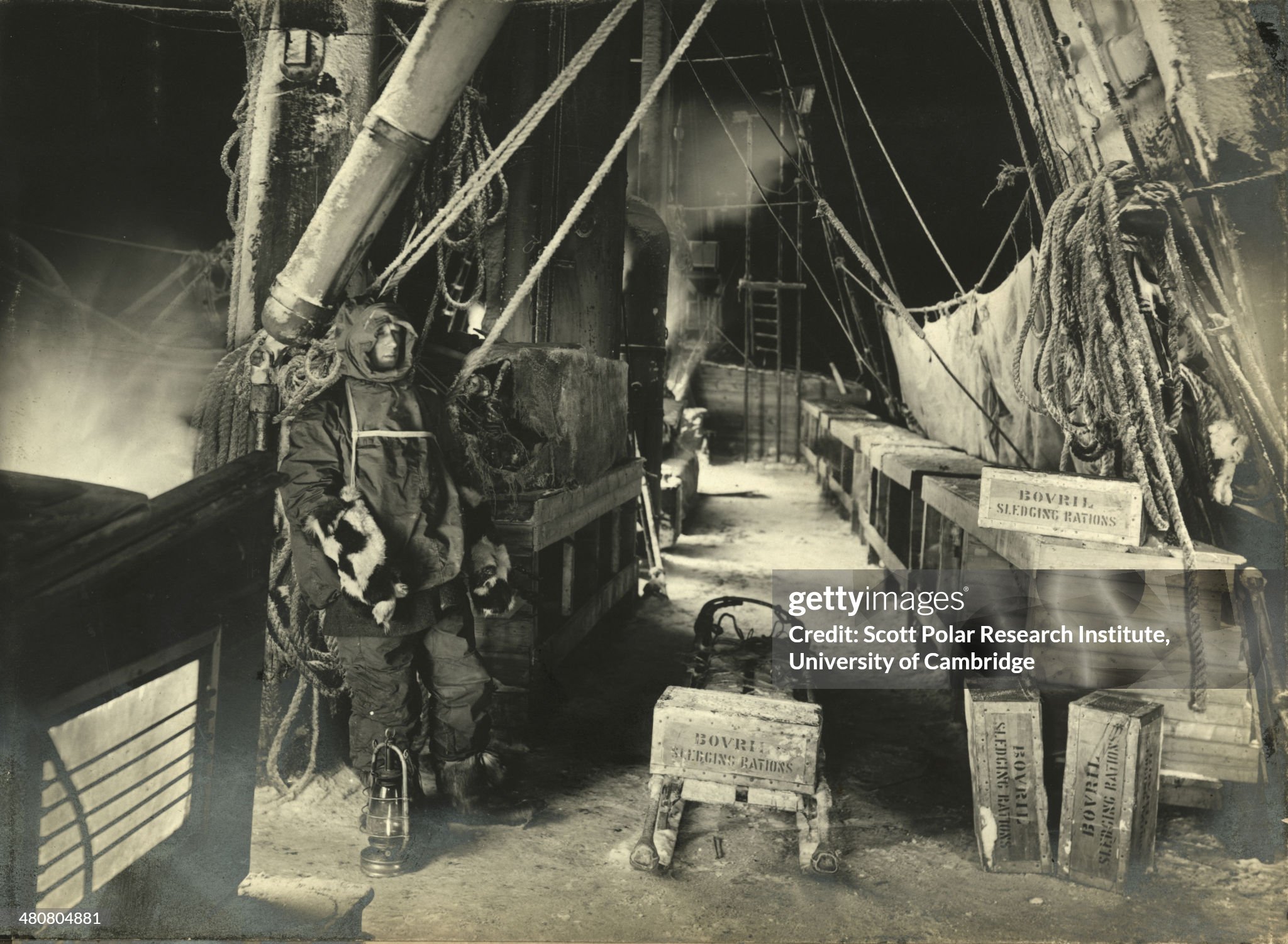
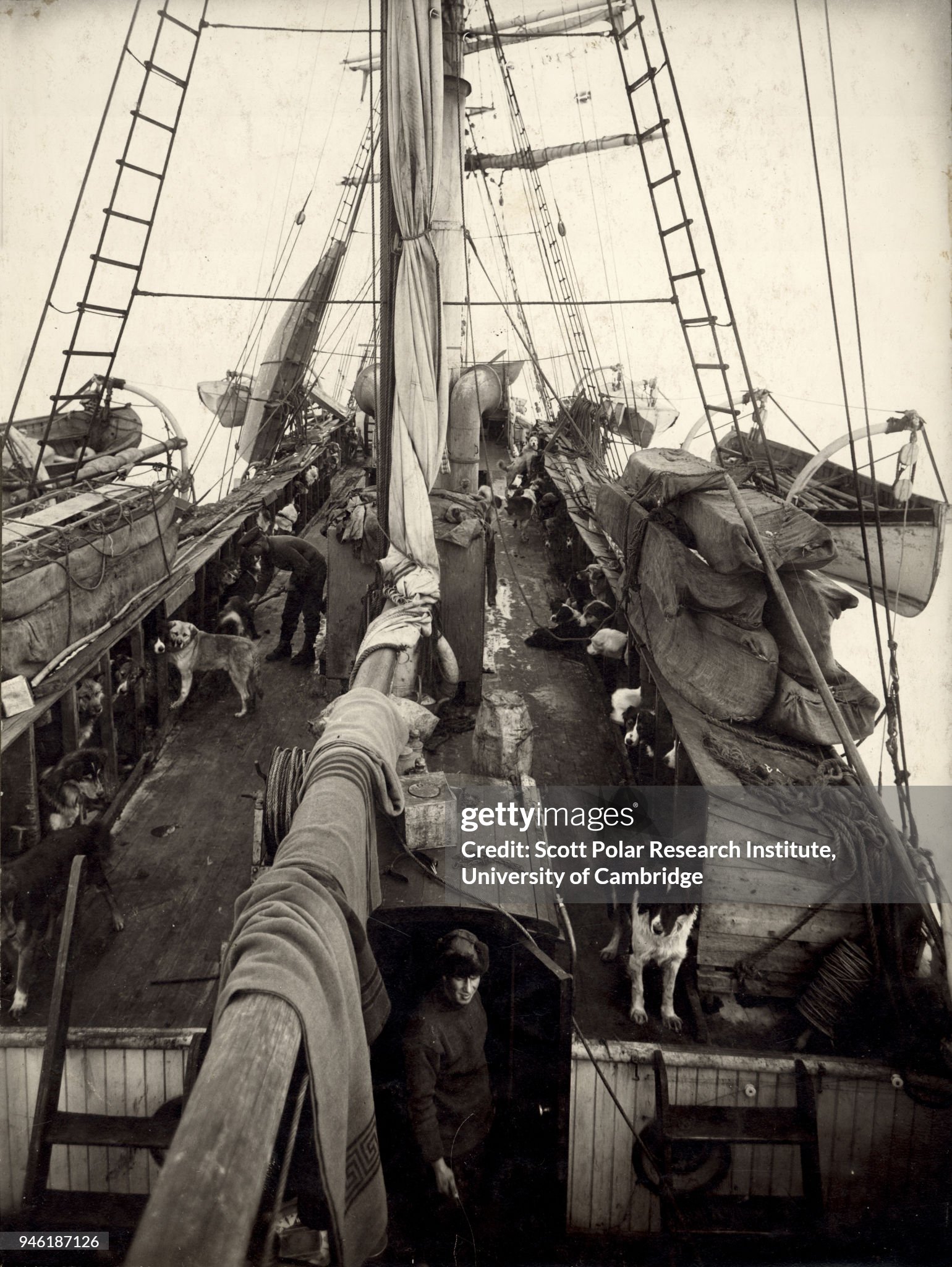
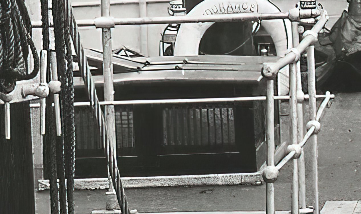
I really want to capture that beatup weathered as well as that scrap lumber look that ships carpenter, Harry McNish, seemed to use in their construction based on the photographs I've seen.
Mike, I've always seen the dog kennels as recycled packing crates, pretty rough and ready. Built in sections of 3 and 4 dogs, sometimes the gap between two sections is roofed over for an extra dog. Probably 1/2 inch planks roughly sawn to length, butt jointed (I think that shingled look is just warped planks). Those forward seem rougher than the rest, possibly they used the best material aft?
The 'Bovril' shot probably the best guide to their construction.
- BobG, Keith Black, Mike Shea and 1 other
-
4
-
On 3/5/2024 at 6:02 AM, dcicero said:
The subject is very interesting!
It is indeed.
Dan, here's a few more clues:
https://www.arbeitskreis-historischer-schiffbau.de/mitglieder/modelle/roemerschiff-victoria/
https://roemerschiffe.de/victoria/

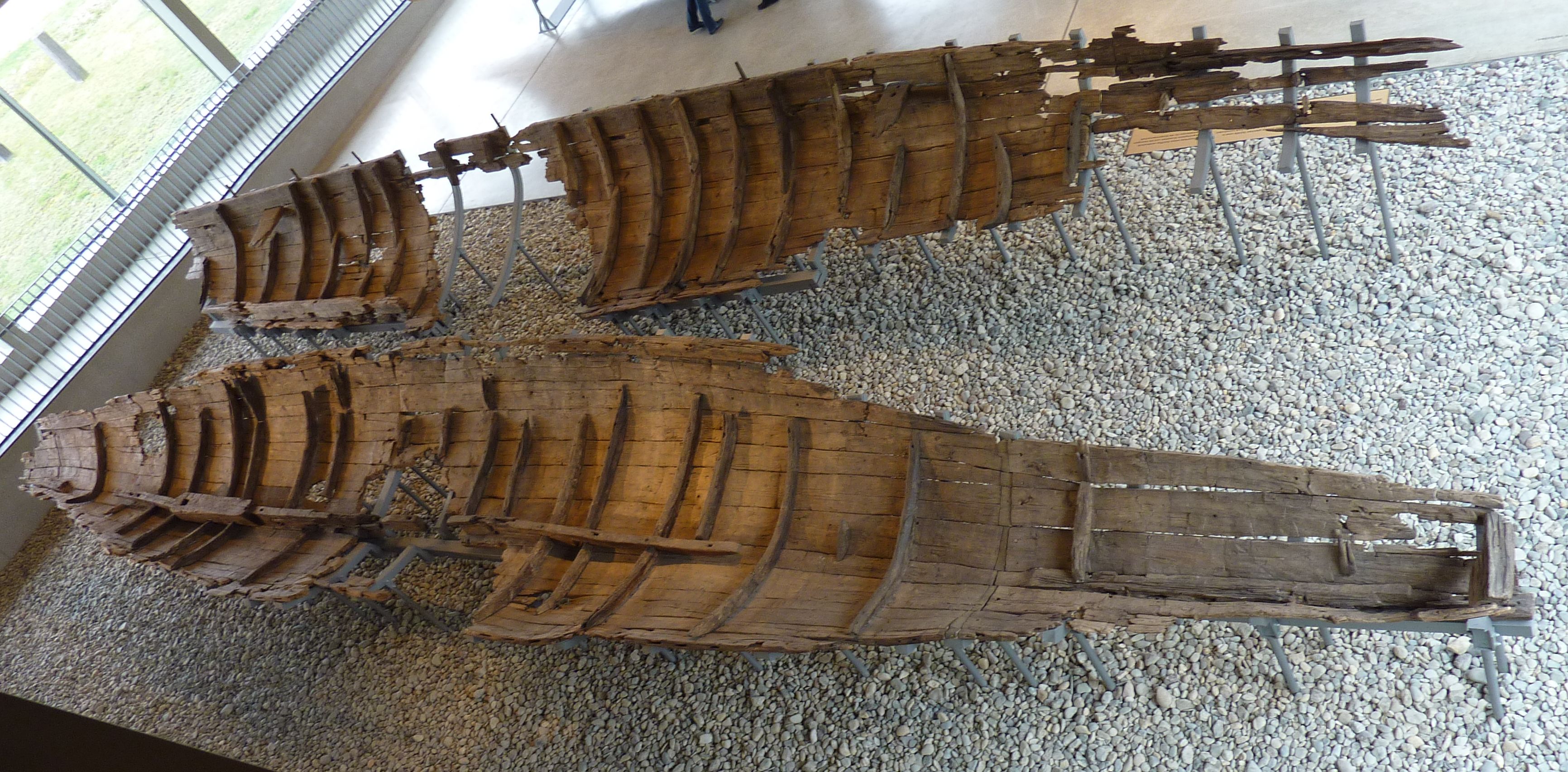

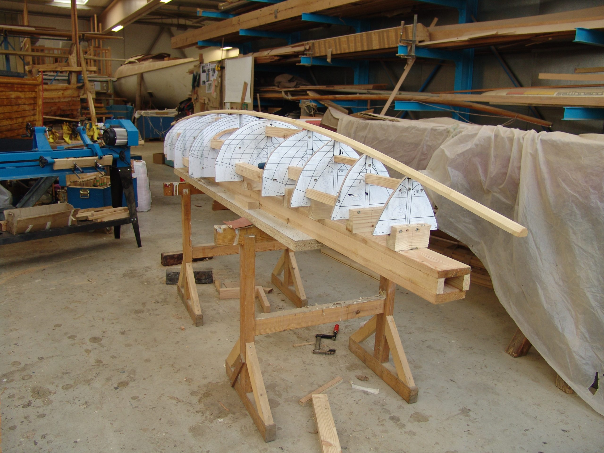
Looking at the last shot I see the midships moulds look to be arcs and the other moulds use the same arc rotated.
Taking the above and adding it to This:
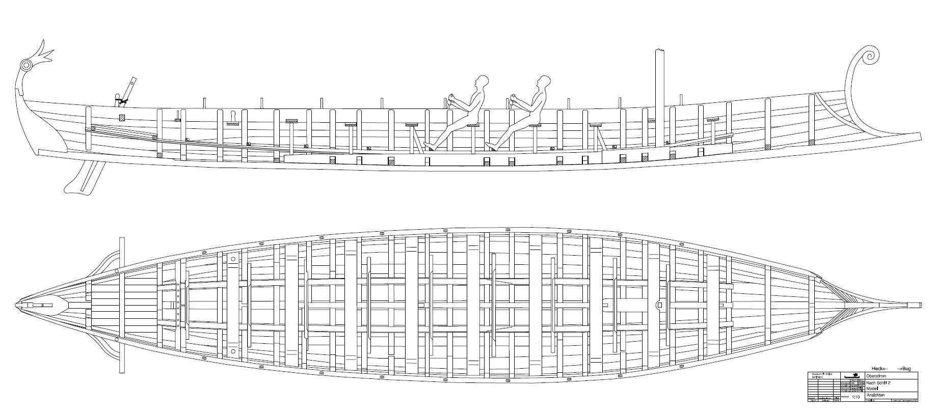
Gives:
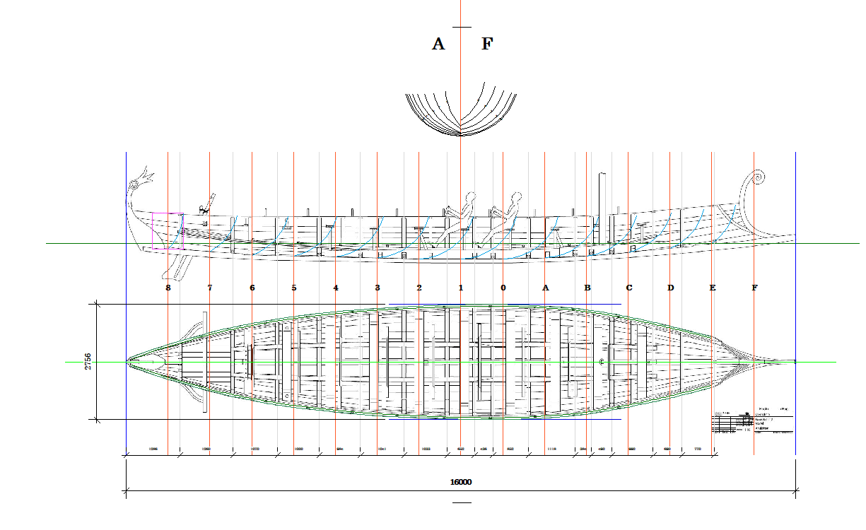
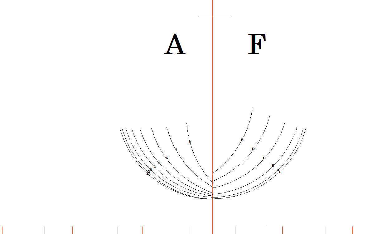
Certainly not 100% right but perhaps 90%? It doesn't include the bow or stern either.
-
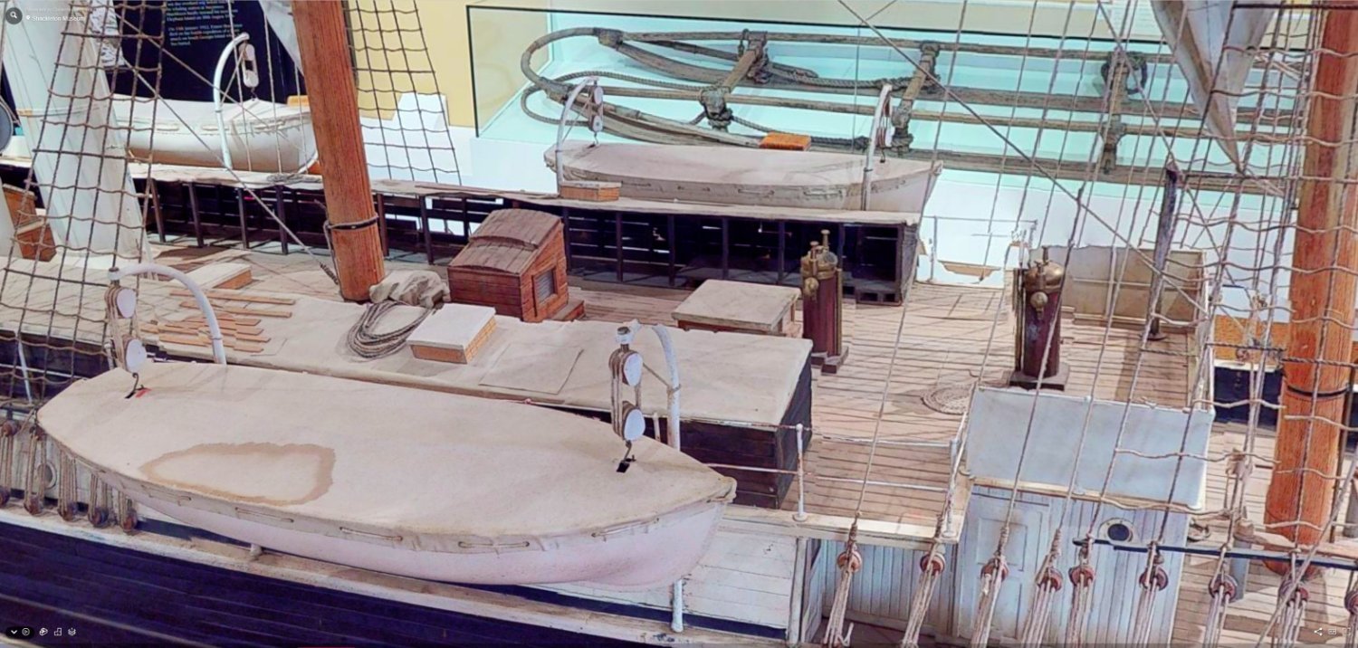
2 hours ago, theoracle09 said:
Endurance model I came across yesterday
A screenshot:
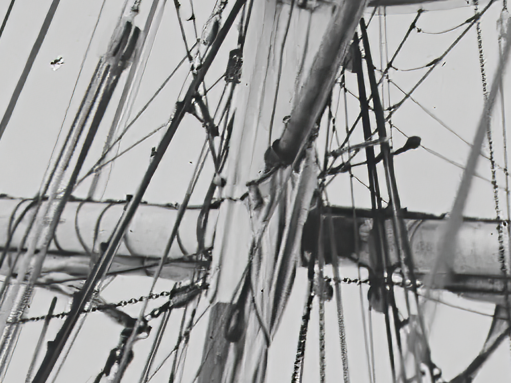
 34 minutes ago, clearway said:
it will be a goose neck fitting - there is a band around the mast
-
-
1 hour ago, theoracle09 said:
I'm afraid I don't know what you mean, Craig?
Brain fade.
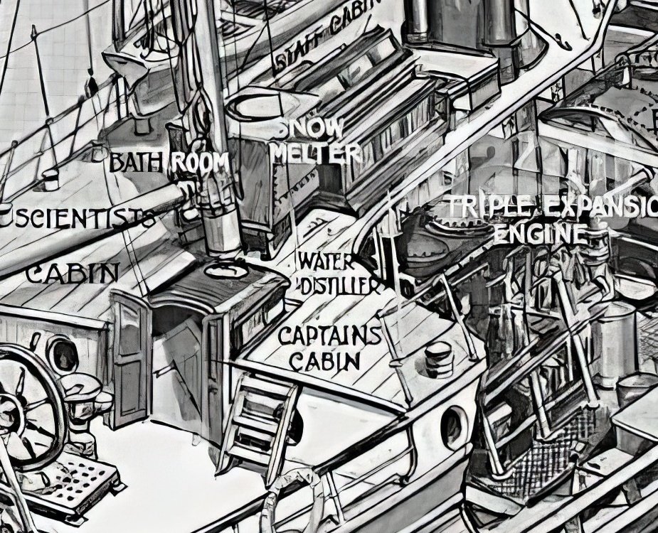
2' tall in the middle, 4' x 4' square, 2 windows each side, hinged centre panel in the roof either side. Azimuth compass a couple of feet forward of it (not shown in this pic), binnacle forward of that.
- HakeZou and theoracle09
-
2
-
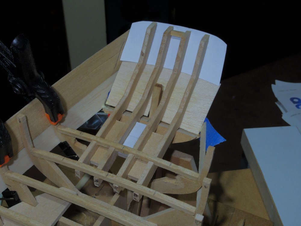
A tiny update representing a lot of head bashing.
The inner pair of counter timbers:
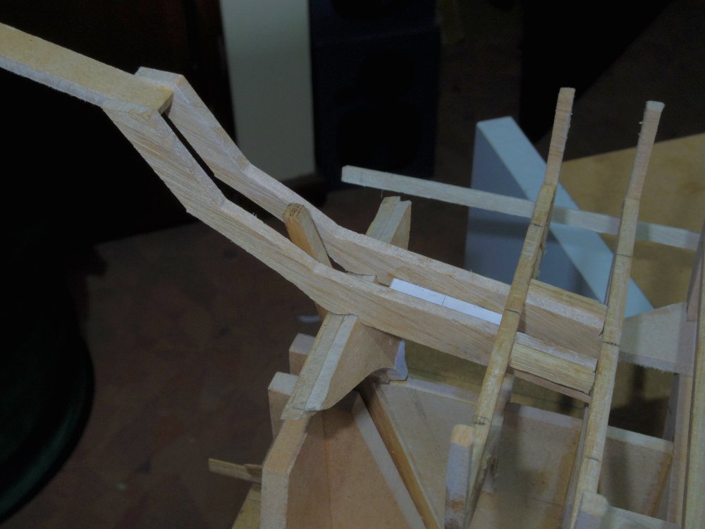
I had to remove 'deck beam' 18 to get them in, all six will be attached to it before being installed as an assembly.
I thought I had the outer counter timbers worked out (several times) but I think I'll have to give up and do them in multiple pieces like Chuck did Cheerful.
-
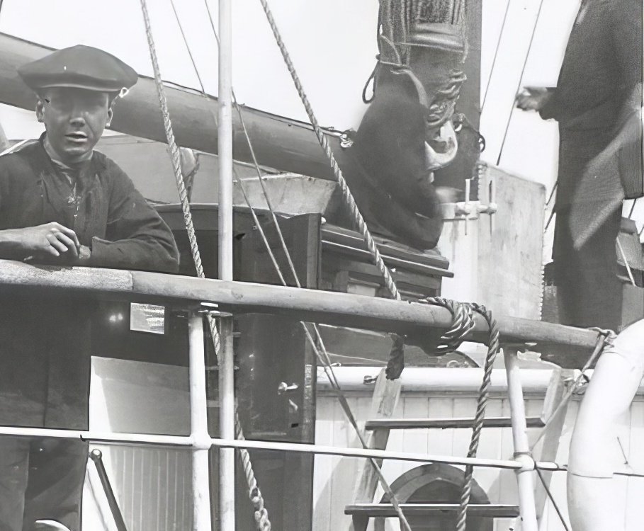
1 hour ago, theoracle09 said:
but can't come up with something I move forward with
I think this is all I've got. The photo seems to confirm the sketch in that it shows the top glass is very steep (behind the guy's legs on the right).
-
3 hours ago, Greg Davis said:
The more I think about it
Greg, A few more thoughts,
No glue, just press fit. Or at worst a tiny dab of PVA on exposed surfaces that can be chiselled off later.
1/4" dowel stepping down at the ends. Perhaps in segments with couplers, slide the coupler along and the dowel is 'cut'. You could cut the disks with side cutters/wire cutters to remove them.
Some thin C.A. into the end grains before boring should give a smoother hole.
- Ryland Craze, FlyingFish, mtaylor and 1 other
-
4
-
1 hour ago, Greg Davis said:
I will slice off a 3mm disk from each form to sit inside each hoop.
I haven't fully thought this out but perhaps bore out these disks to take a shaft for alignment? Then your supports could support the shaft and be standardised, some fixed to a base some moveable to wherever you're working.
- Canute, FlyingFish, mtaylor and 1 other
-
4
-
26 minutes ago, Tony Hunt said:
Looking really good Craig! The hull looks nice and fair.
Thanks Tony. Biggest worry at the moment (apart from everything else) is the MDF bulwarks, I have to fair one side unsupported so that I can plank or line them so they are supported to fair the other 🤷♂️
-
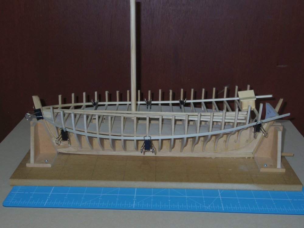
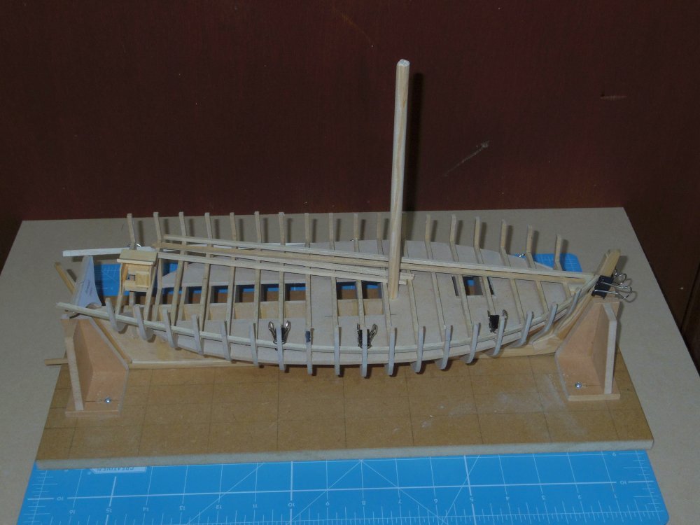
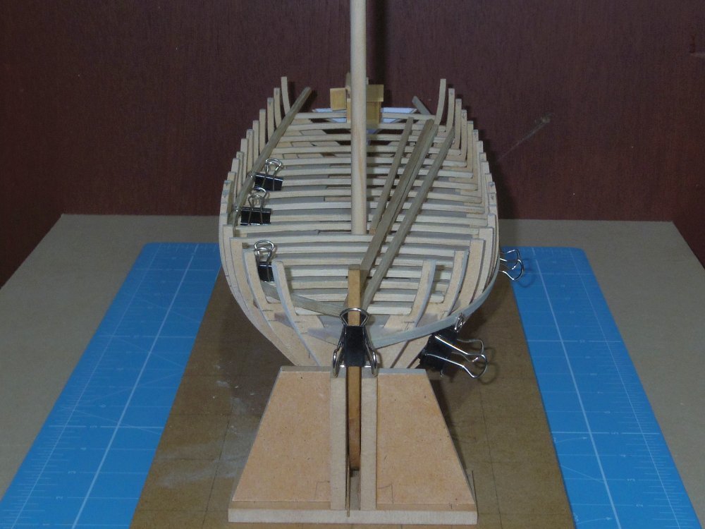
Some progress, in a forwards direction

Build board built, 'deck beams' bent, everything glued up to and inc the 'deck beams'.
Wale being test fitted (again), waterway being worked out (they're next I think).
After the waterways it'll have to be the counter timbers, that will be fun.
-
-
-


HM Cutter Speedy 1828 by oakheart - from plans drawn by Bill Shoulders in 1972
in - Build logs for subjects built 1801 - 1850
Posted
Looks good to me.