HOLIDAY DONATION DRIVE - SUPPORT MSW - DO YOUR PART TO KEEP THIS GREAT FORUM GOING! (Only 13 donations so far - C'mon guys!)
×


Mahuna
-
Posts
1,504 -
Joined
-
Last visited
Content Type
Profiles
Forums
Gallery
Events
Everything posted by Mahuna
-
 Hi Patrick - your presentation of Shadow is elegant in its simplicity. I've never heard of using shoe polish as a finish on wood, but it certainly seems to do the trick. Congratulations on another great build. Your fleet is quite impressive, and I'm looking forward to seeing what's next.
 -
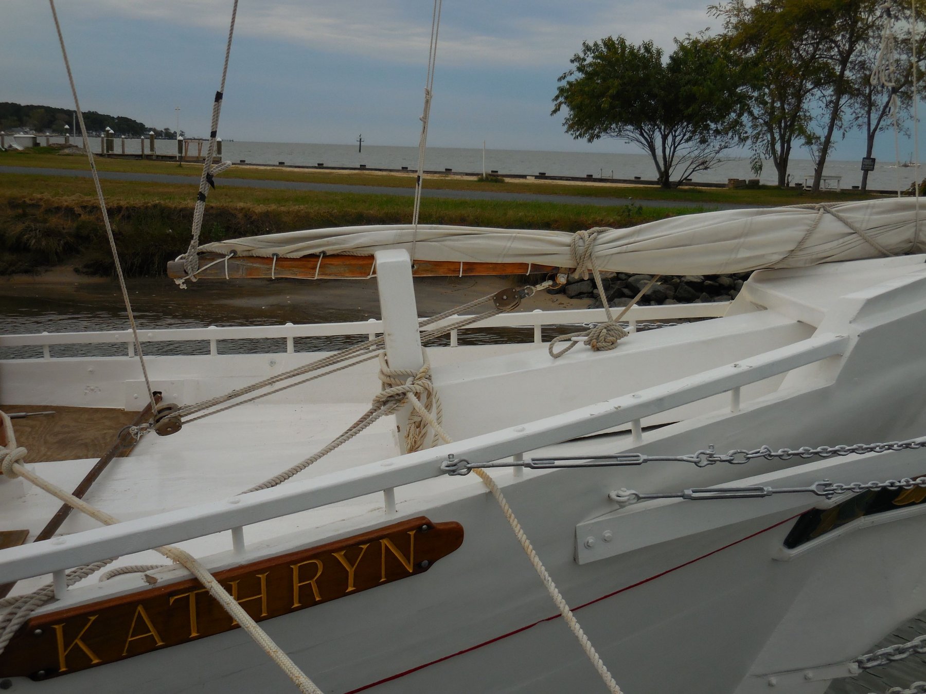
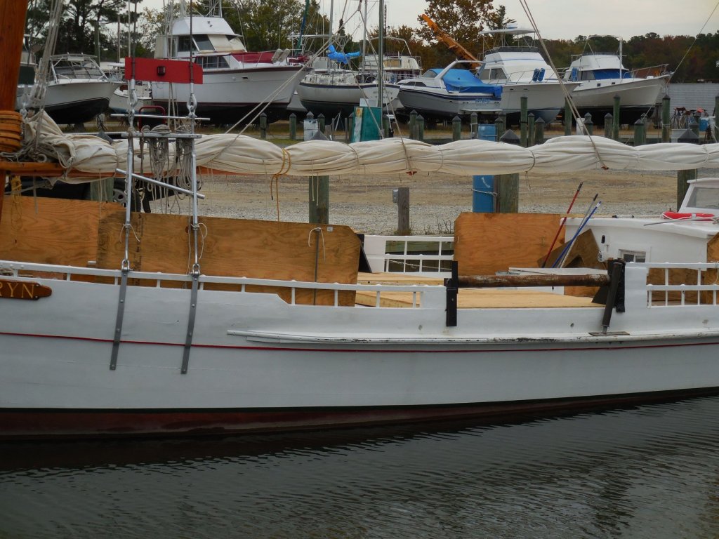
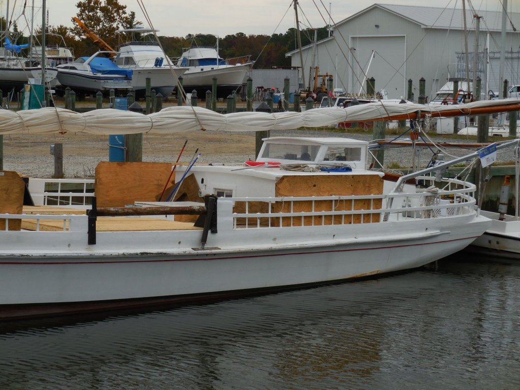
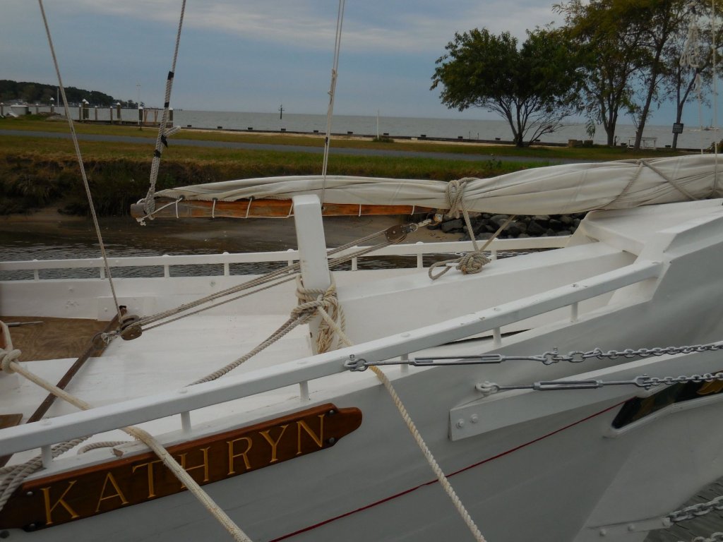
Thanks Peter. Your models have been a major influence for me. I'm still trying to decide on sails - but I'm leaning towards furled sails at this point. Hi Brian - great to hear from you. I originally thought about using styrene for the stanchions, but I'm glad I used brass - much stronger. Thanks Ron and Tom for the kind words. Hi Patrick. Yeah, Kathryn is beautiful when seen in person. She stands out from the other skipjacks still in use. I'm sure she was powerful when dredging under sail, but now she depends on the power of the yawl boat when dredging. I'd love to see her under sail during the annual skipjack races - maybe some day.....
-
Thanks Popeye. The installation of the rails did go fairly quickly, mainly because of the shaping and drilling that had already been done in a prior step. It would have been much more difficult and time consuming without that previous work.
-
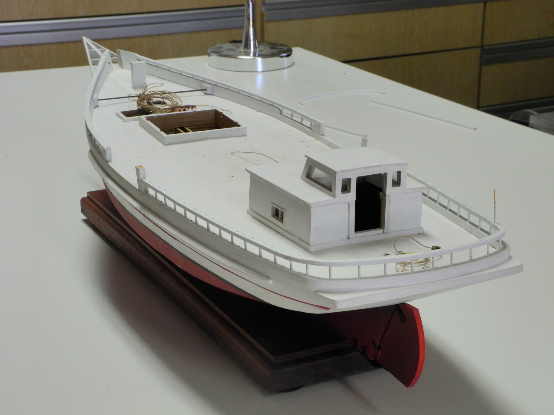
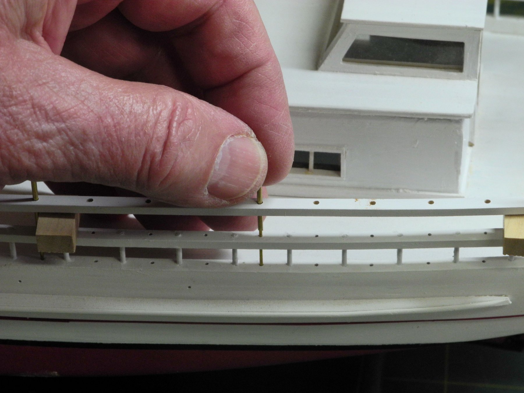
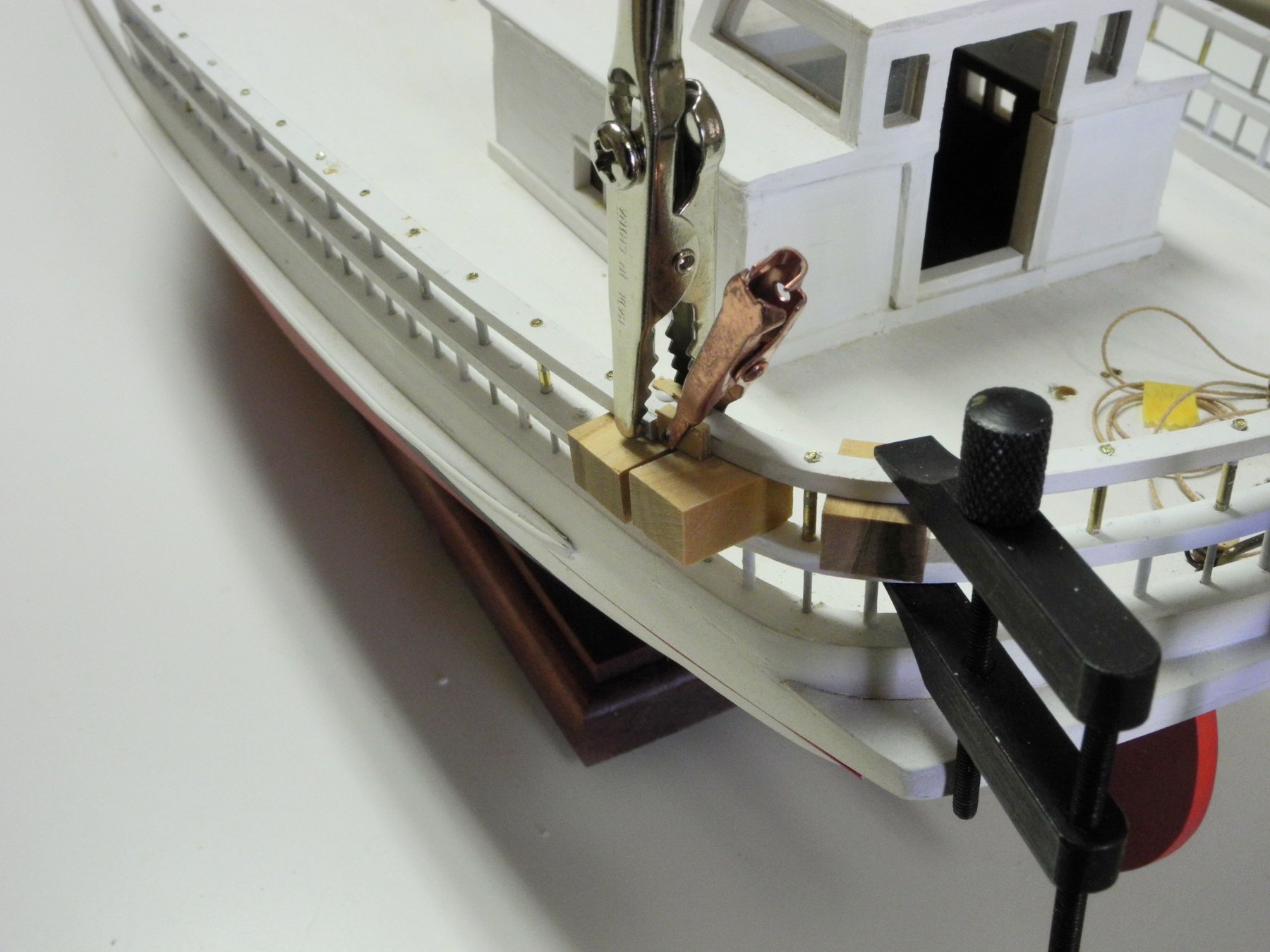
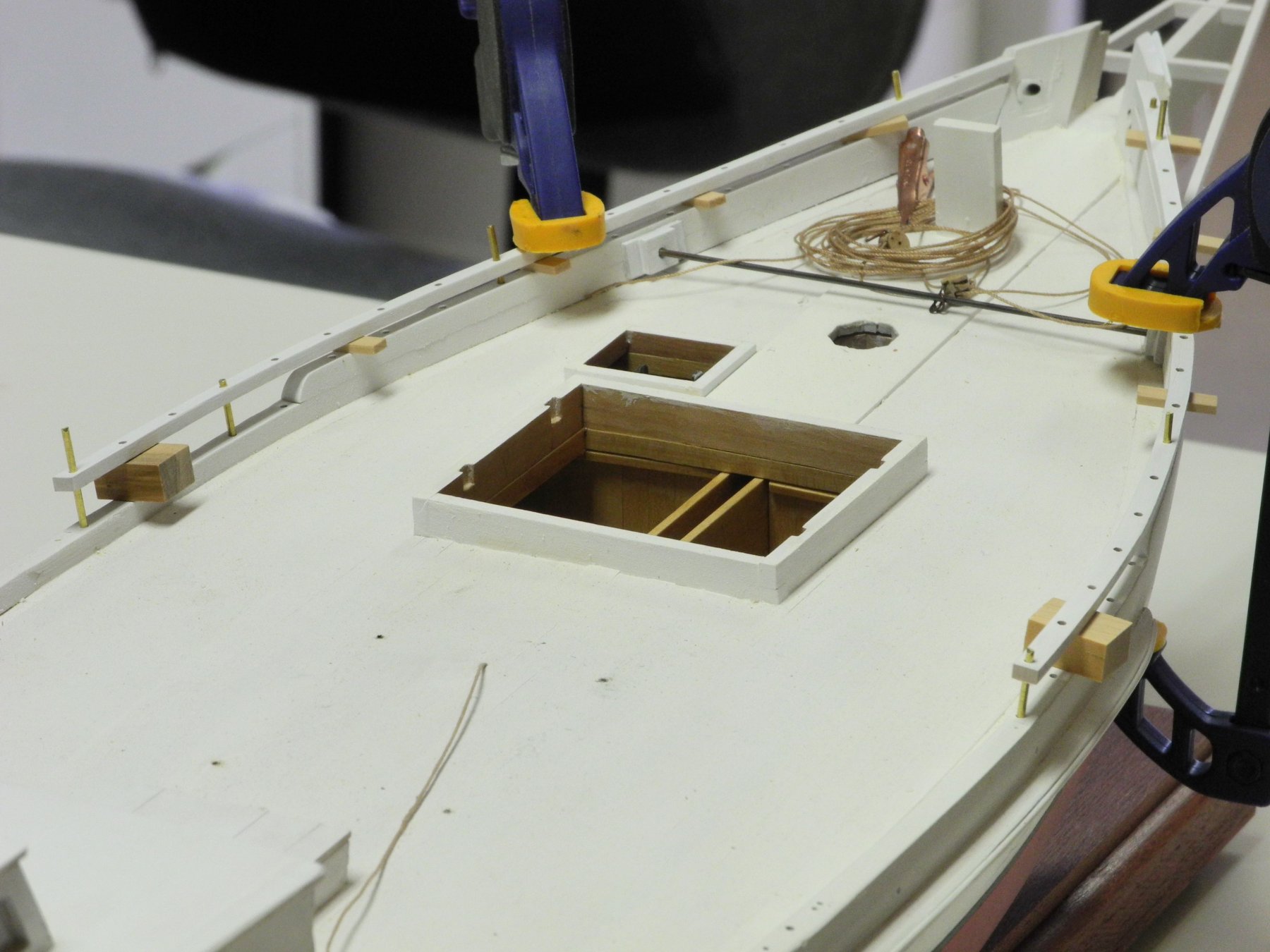
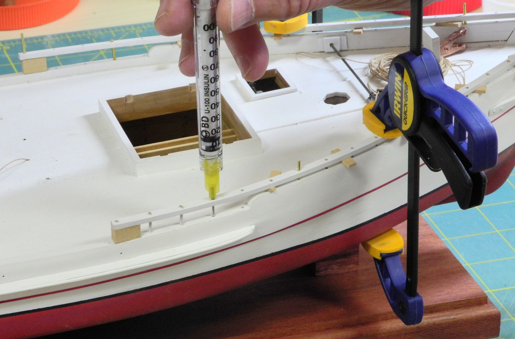
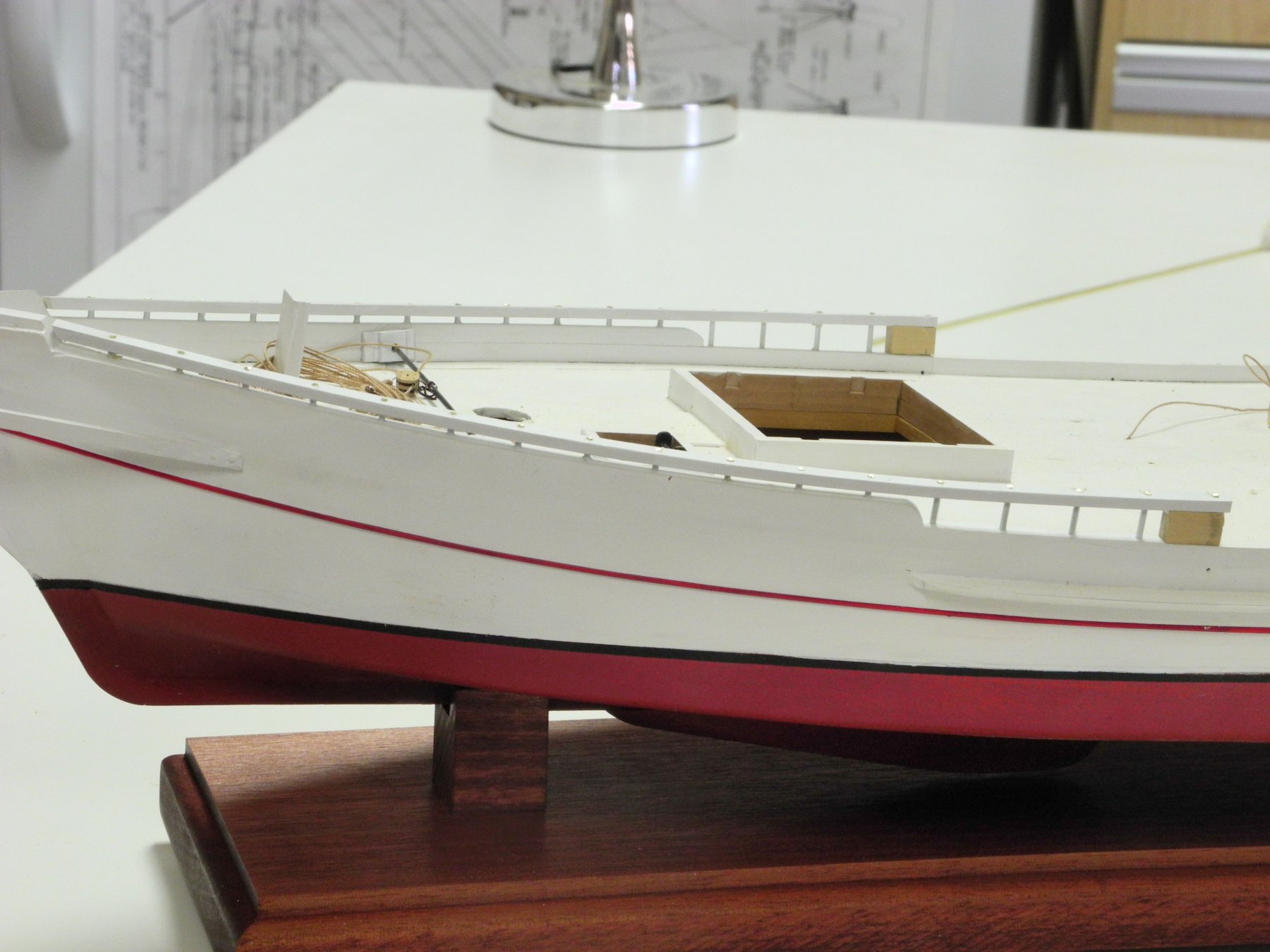
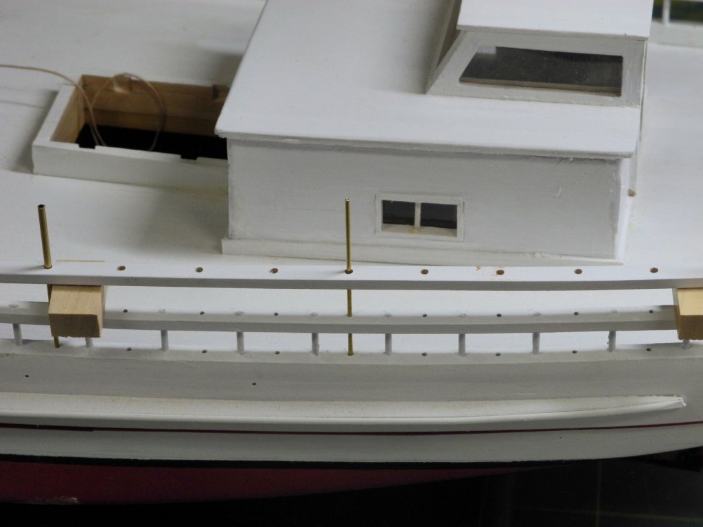
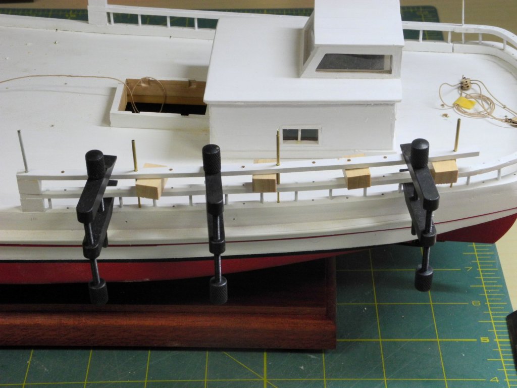
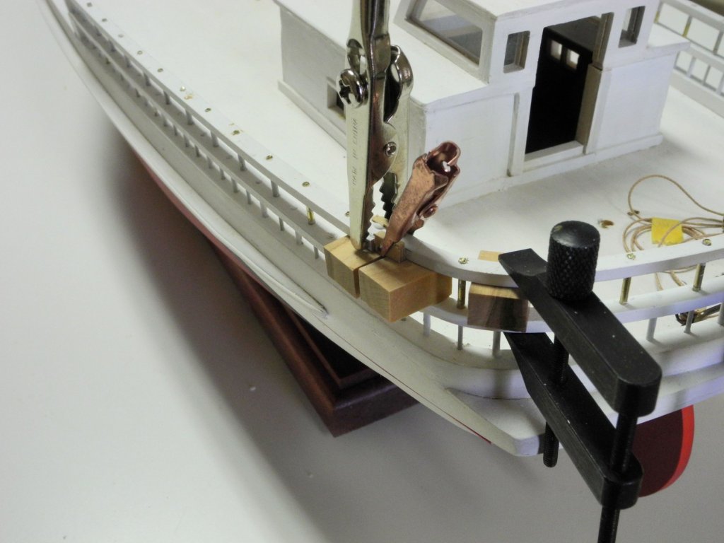
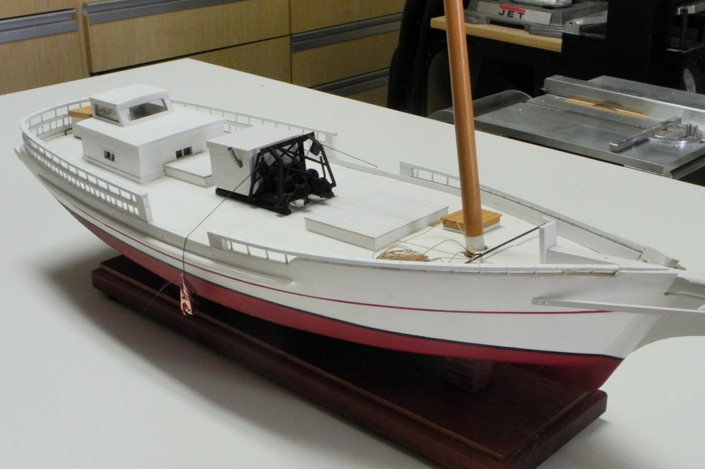
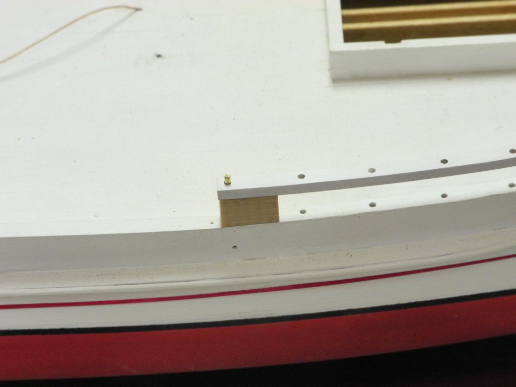
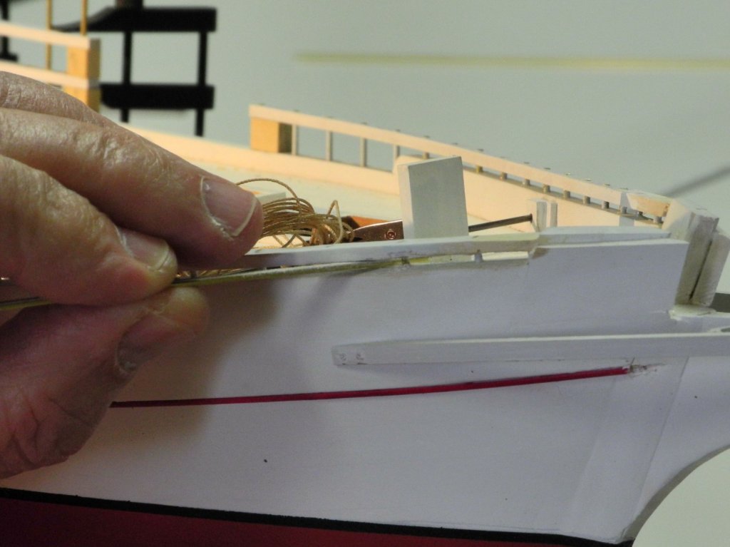
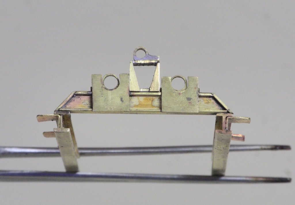
Part 55 – Rails cont’d As described in the previous post, Kathryn’s aft head rails are configured as double rails, with twice as many stanchions under the lower of the two rails as are under the upper rail. Installation of the aft lower head rail followed the same process as the installation of the forward head rail, with the 1.5” (3/64” on the model) stanchions being installed in the appropriate holes. This left the smaller holes for the 1” stanchions (1/32” on the model) empty. These holes are used for the stanchions supporting BOTH the lower head rail and the upper head rail. A 1/32” rod, long enough to span the distance from the log rail to above the upper head rail, was installed. As can be seen from the above photo, this rod was a snug fit in the log rail and the lower head rail, but was a loose fit in the upper head rail. A 3/64” tube was then slid over the 1/32” rod until it met the lower head rail. The above photos were taken during the initial dry fit of the aft upper head rail. This process was followed for the actual gluing of the stanchions. Once the head rail was secured in this setup, the permanent stanchions were installed in the open stanchion positions and then the temporary stanchions were removed and replaced by the permanent stanchions. As with the forward head rails, there was a significant alignment issue between the side rails and the rear rails. Wood blocks were installed to fill out the offending areas, and then wood filler and modeling paste were used to finish the area. The following photos show Kathryn with all rails installed. This represents a major milestone for me, since the hull construction is now completed. The subject of the next post will be the installation of a pushboat bumper at Kathryn’s stern. Thanks everyone!


- 878 replies
-
- 18
-

-
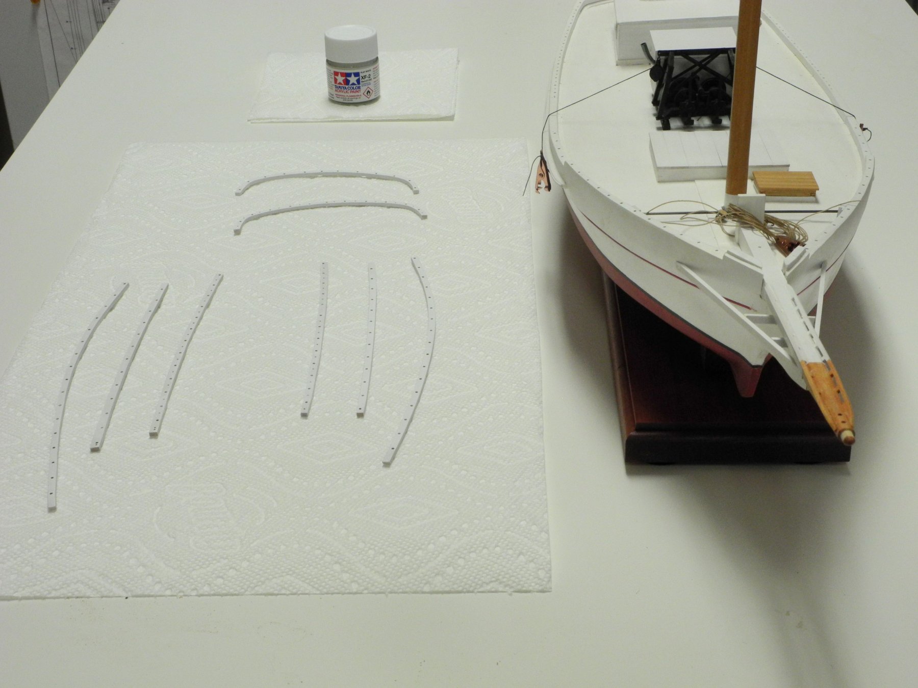
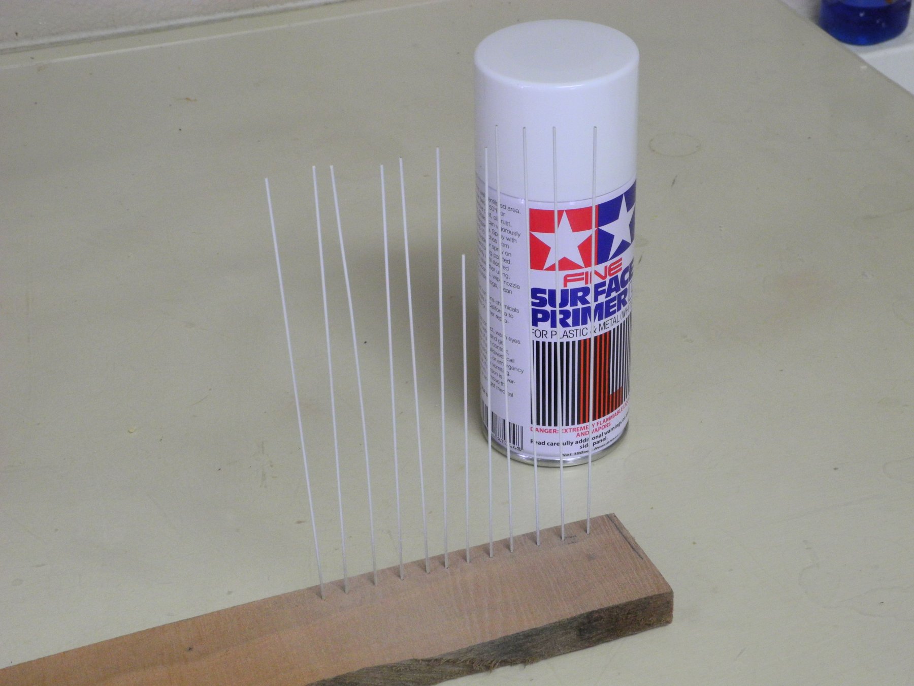
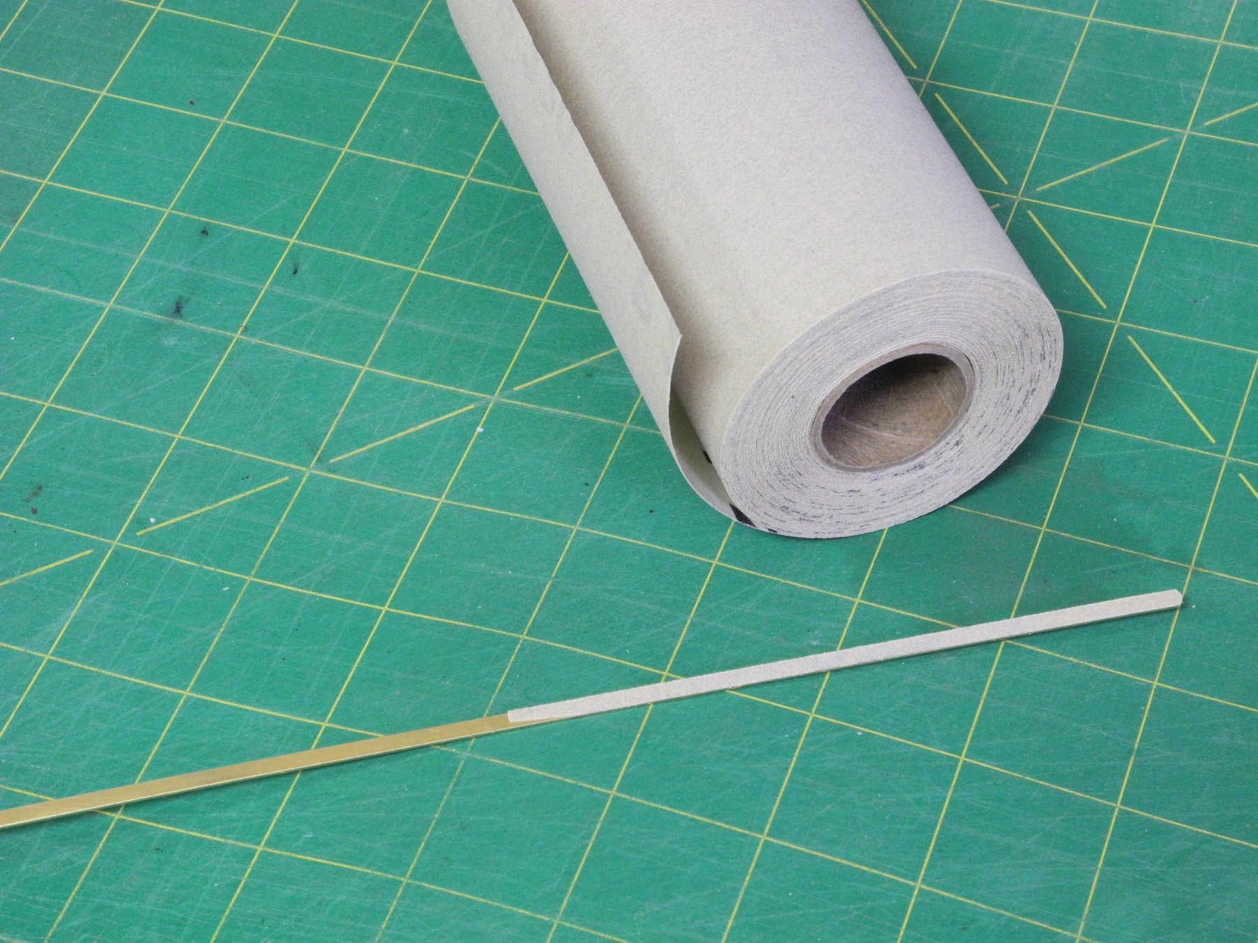
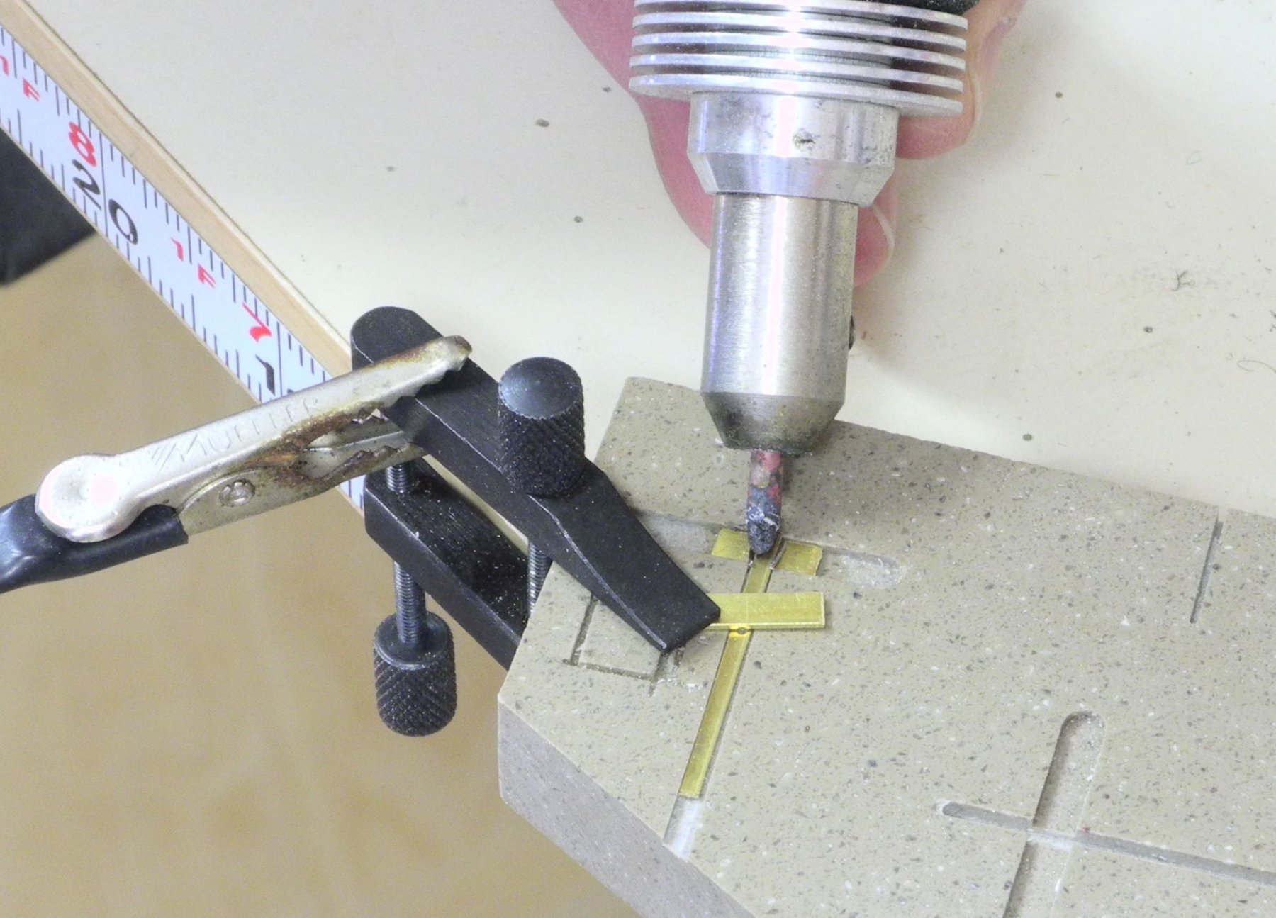
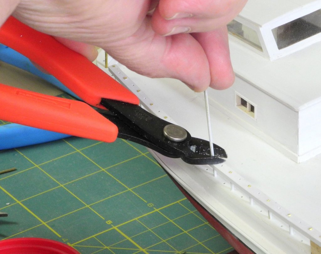
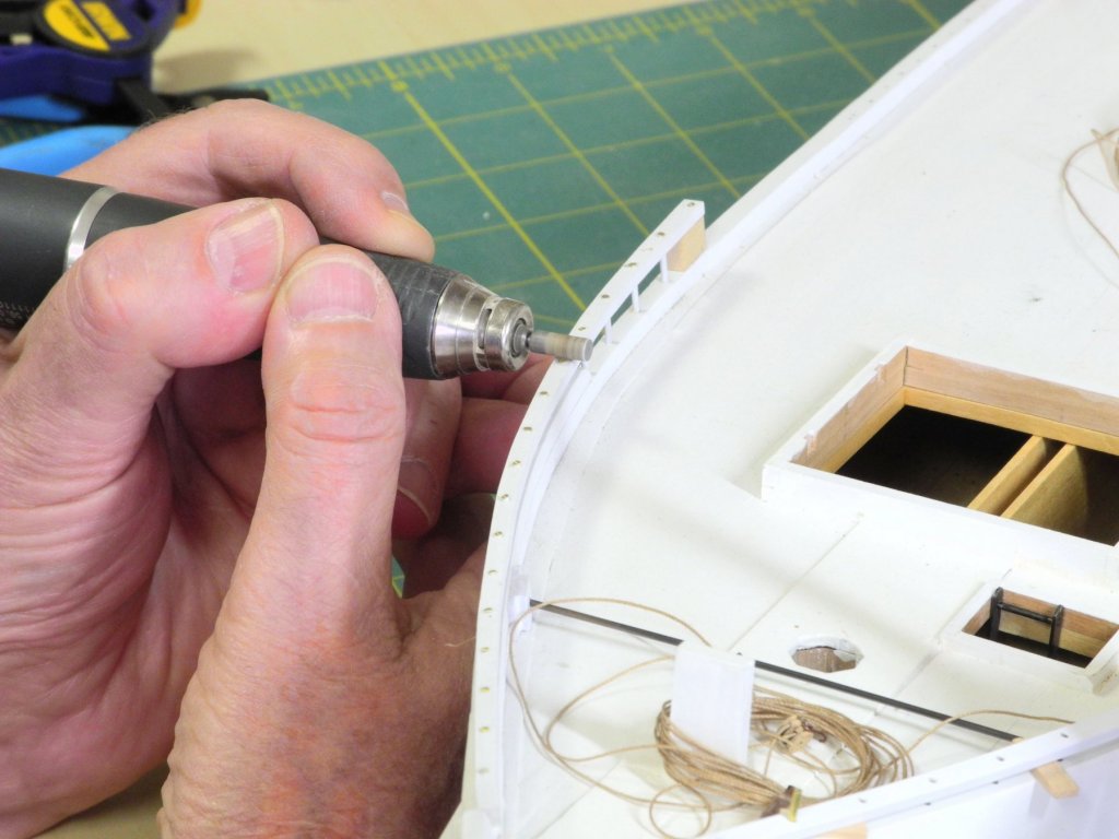
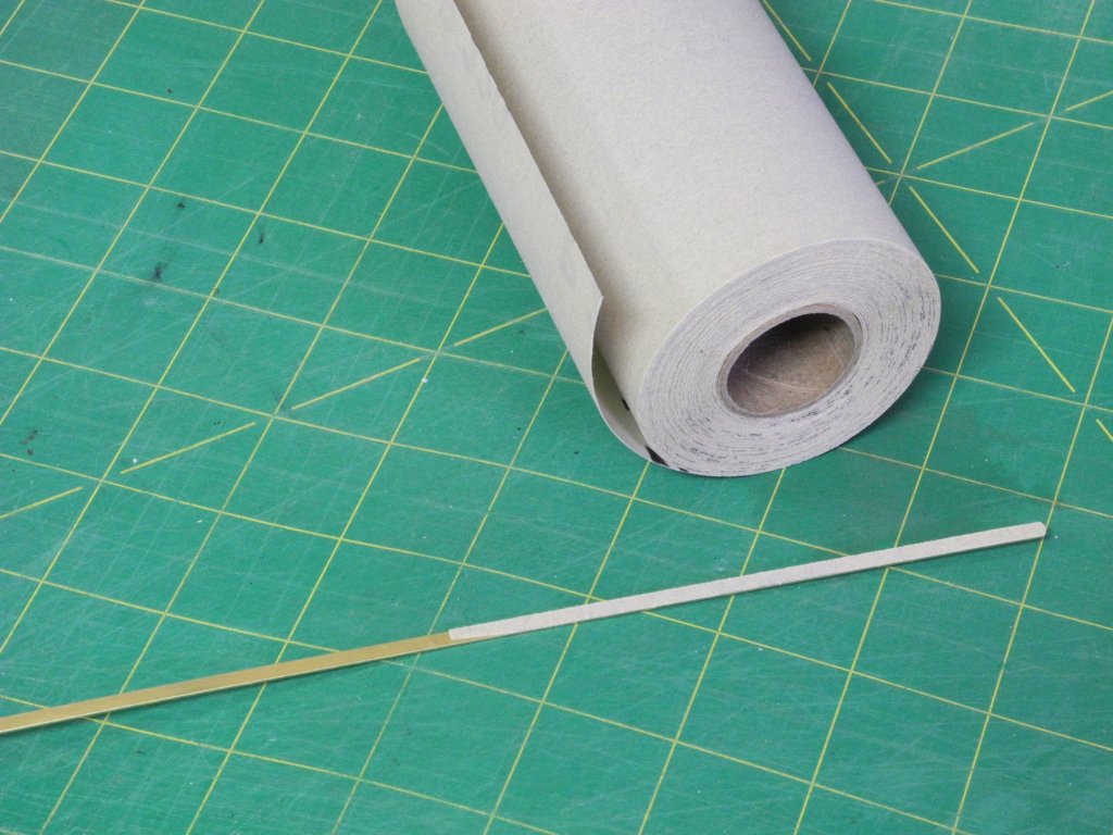
Part 54 – Rails The components for the log rails and head rails were made last July, and the process for forming and drilling them was described in Part 29. The forward rails consist of a log rail that is doubled for most of the forward part, topped by a head rail held with 1.5” iron stanchions. The aft rails consist of a single log rail topped by two head rails. The stanchion arrangement is fairly complex. There are 1.5” iron stanchions under the lower head rail that are spaced consistent with the forward stanchion spacing. However, between these stanchions are 1” stanchions at the halfway mark between the larger stanchions. The upper head rail is supported by 1.5” stanchions that are above and in line with the 1” stanchions. 3/64 brass rod was used for the 1.5” stanchions supporting the forward head rail and the lower of the aft head rails. 1/32 brass rod was used for the 1” stanchions supporting the lower aft head rail. 3/64”brass tubing was used for the 1.5” stanchions supporting the upper aft head rail. The rails were painted prior to construction, and the brass rod and tubing was primed at the same time. Spacers were used to ensure that the rails were evenly spaced from the log rail. There is a solid block at the aft end of the forward head rail (and also at the forward end of the aft head rails). These blocks support the mounting hardware for the dredge rollers. The installation of this block was the first step in installing the head rail. All of the mounting holes for the stanchions were pre-drilled in the log and head rail components, as covered in Part 29. Glue was injected into the pre-drilled holes and the stanchions were installed. The excess glue was wiped off with a wet brush, and when the glue was set the end of the stanchion was clipped off. A rotary tool with a diamond cylinder was used to smooth and reduce the visible end of the stanchions. The caps of the stanchions are apparent in the photos of Kathryn, so the stanchion ends were left protruding slightly on the model. The head rails did not line up perfectly with the knightheads, since I did not sufficiently allow for the flare at the bow. This was corrected by the use of wood filler and some reshaping of the forward part of the head rail. A brass strip was used as a form for the filler, to achieve a fair flow of the head rail. The space under the forward part of the head rail was very tight, so I made a sanding tool from brass strip .025 thick with adhesive backed sandpaper attached to one side. After the final shaping, the head rail was painted where necessary. The construction of the forward head rail was fairly simple when compared to the aft head rails. That will be the subject of the next post. Thanks everyone!


- 878 replies
-
- 21
-
-
Thanks, Carl. When I'm dealing with some issues I find that it's better to put them aside for a while , if possible, and hope that a solution or process will present itself later (typically when I wake up in the middle of the night ).
-
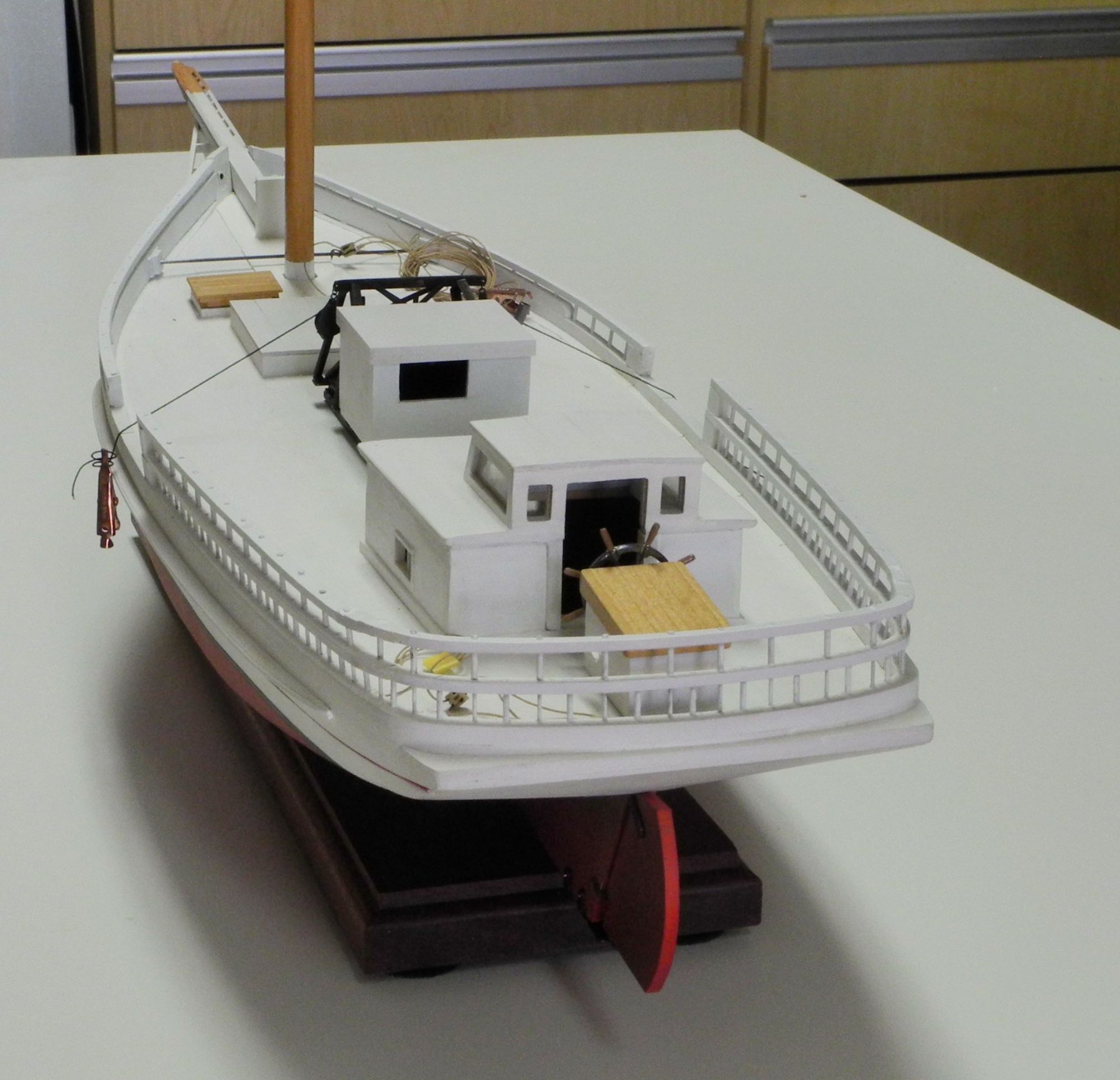
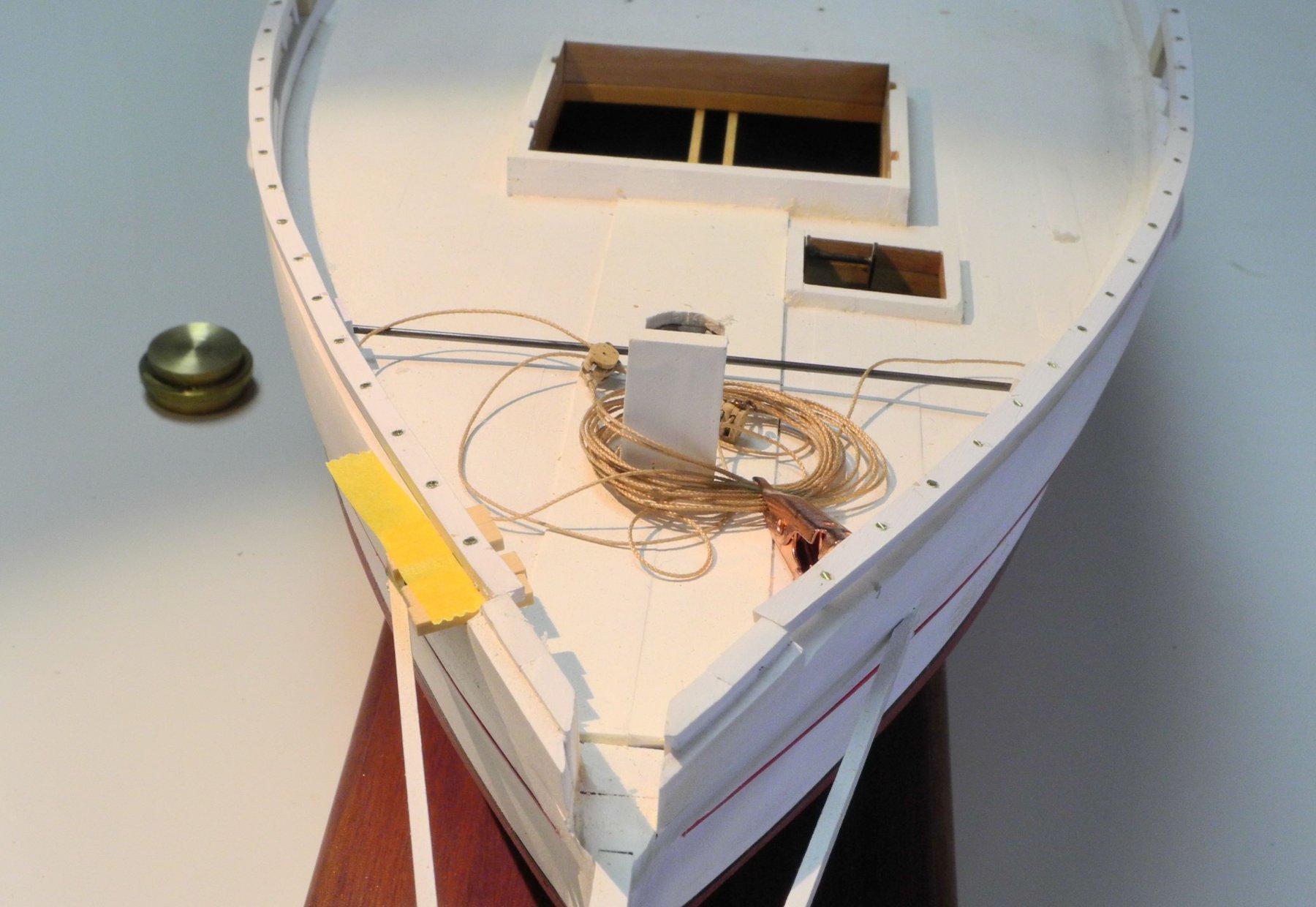
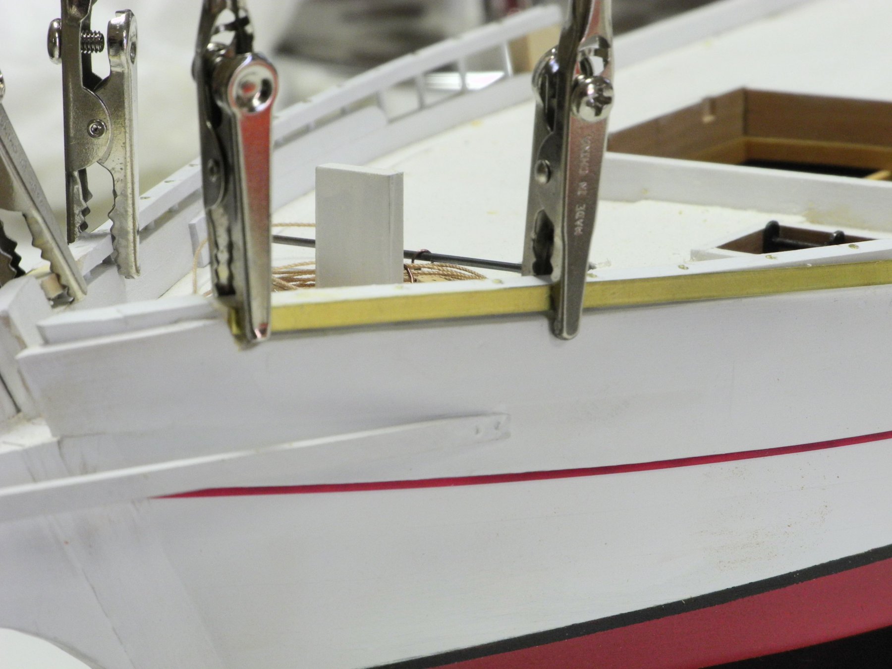
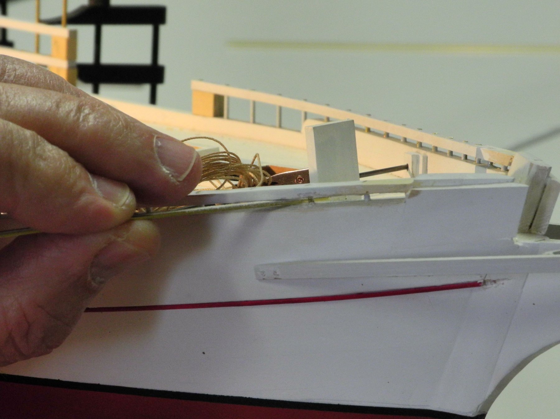
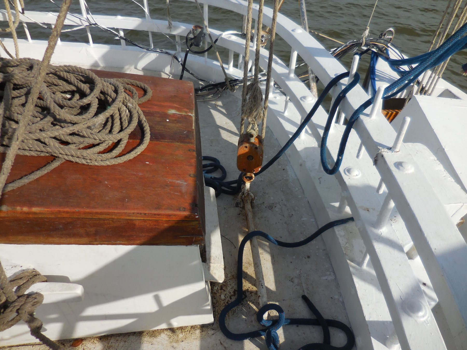
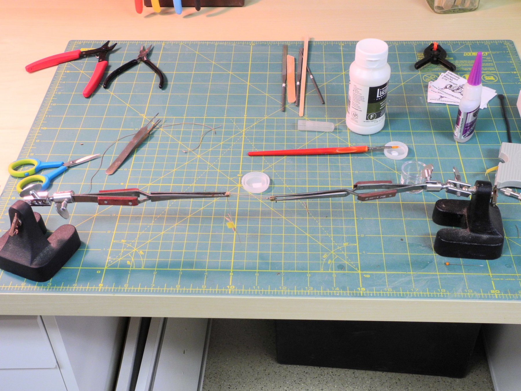
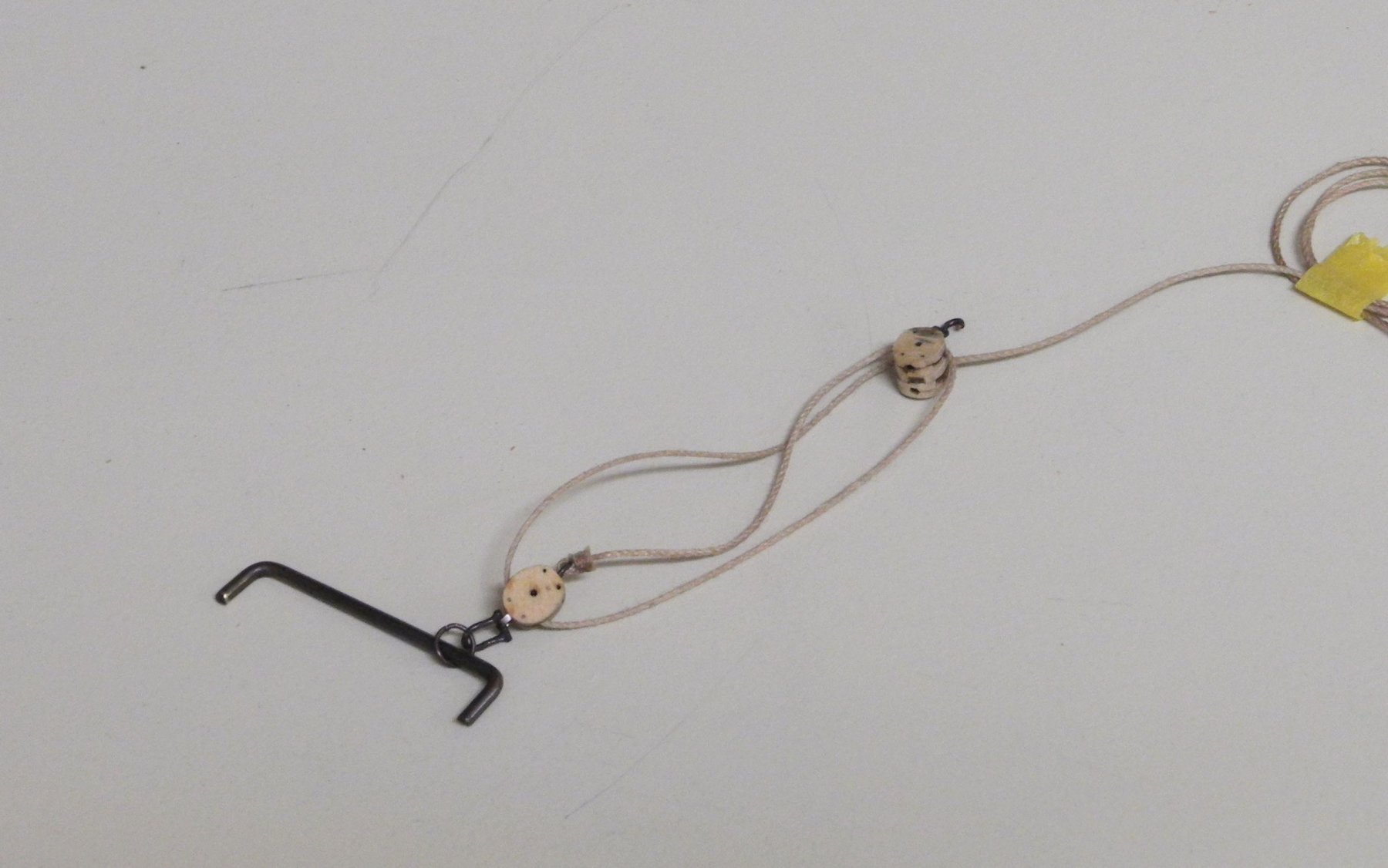
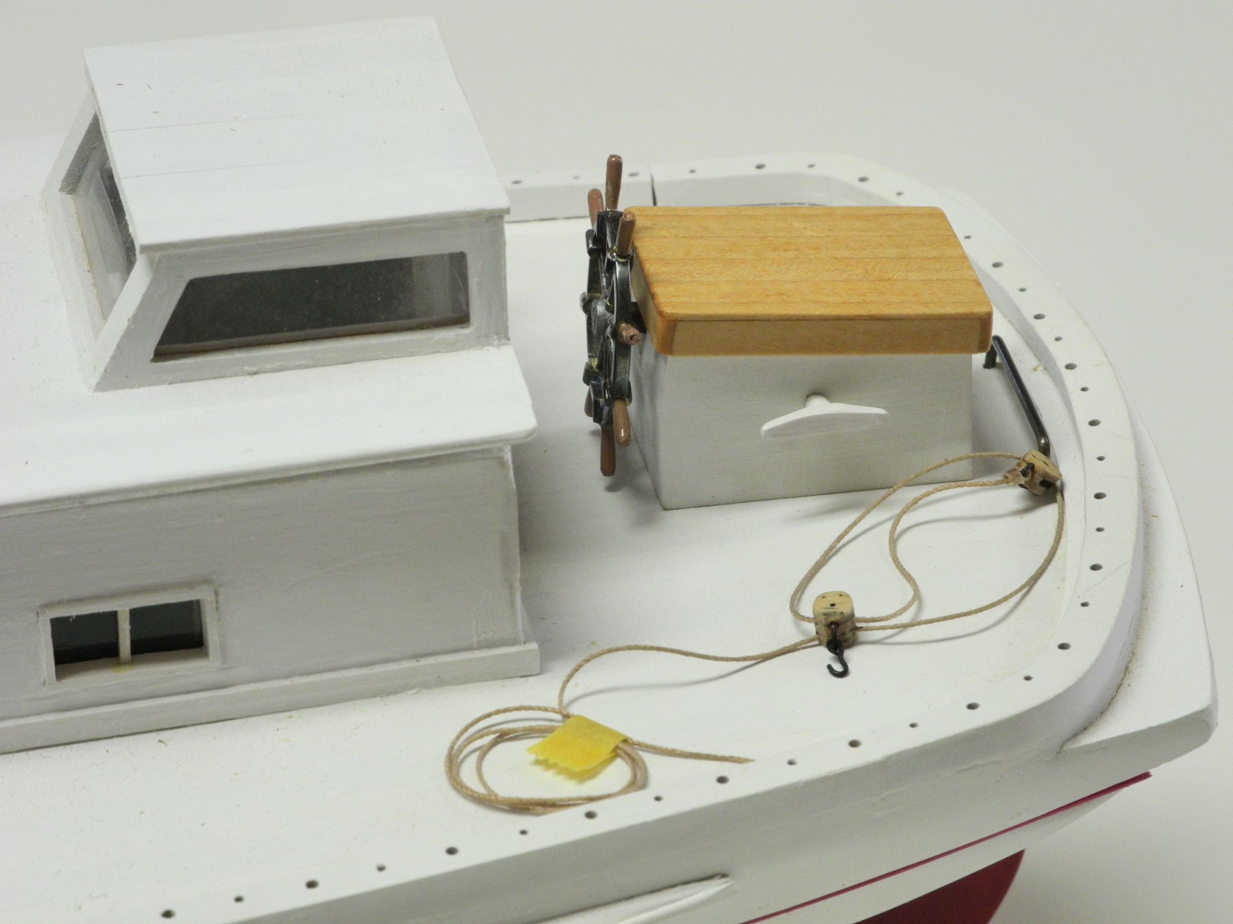
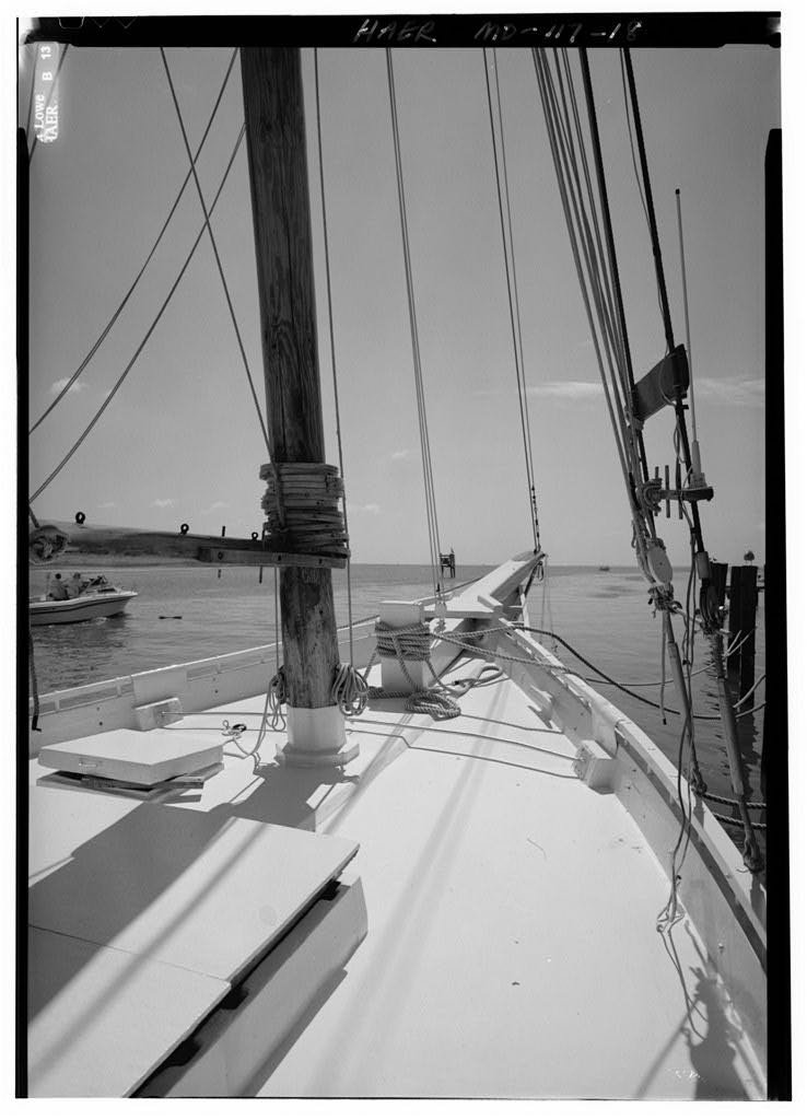
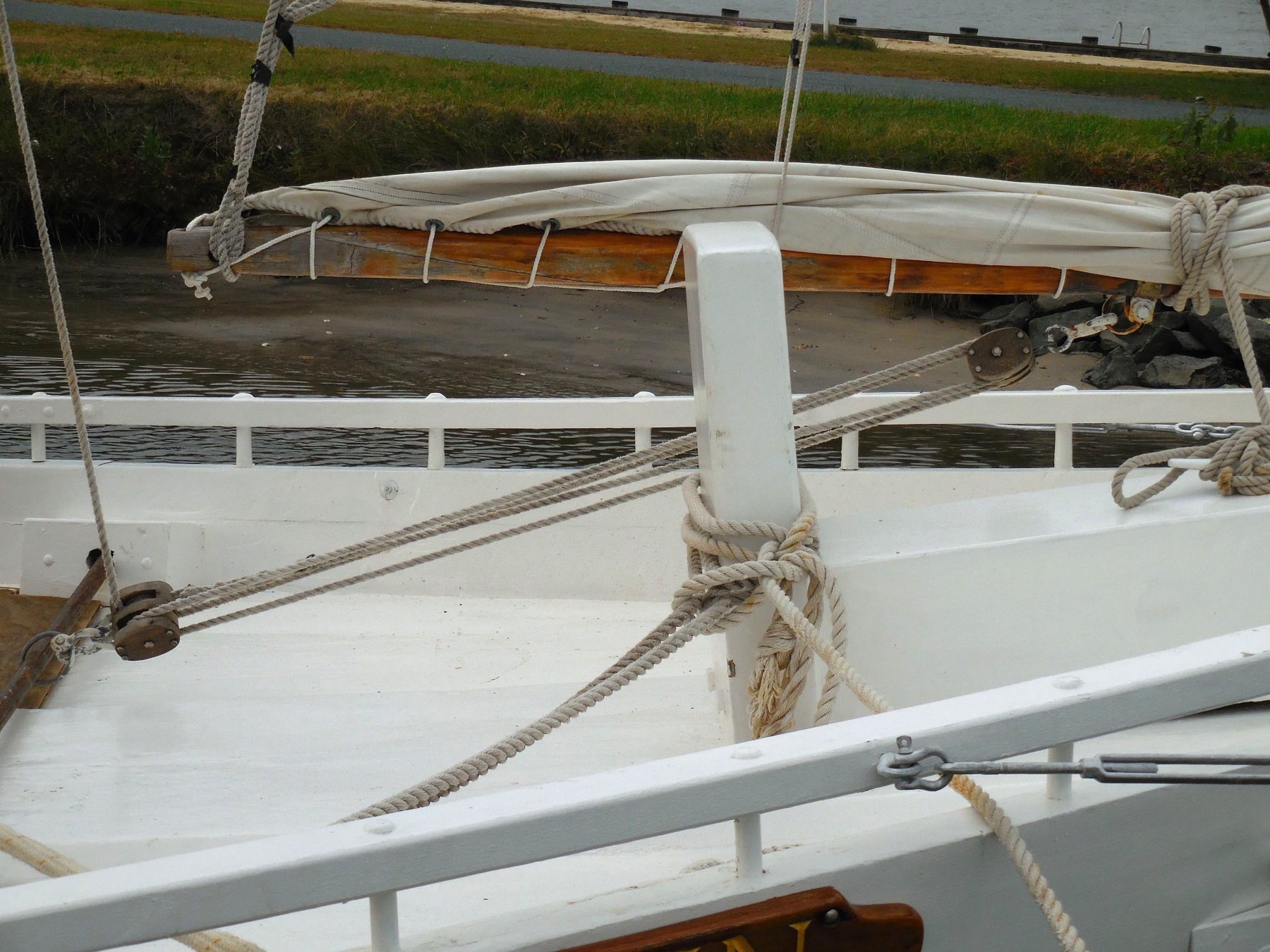
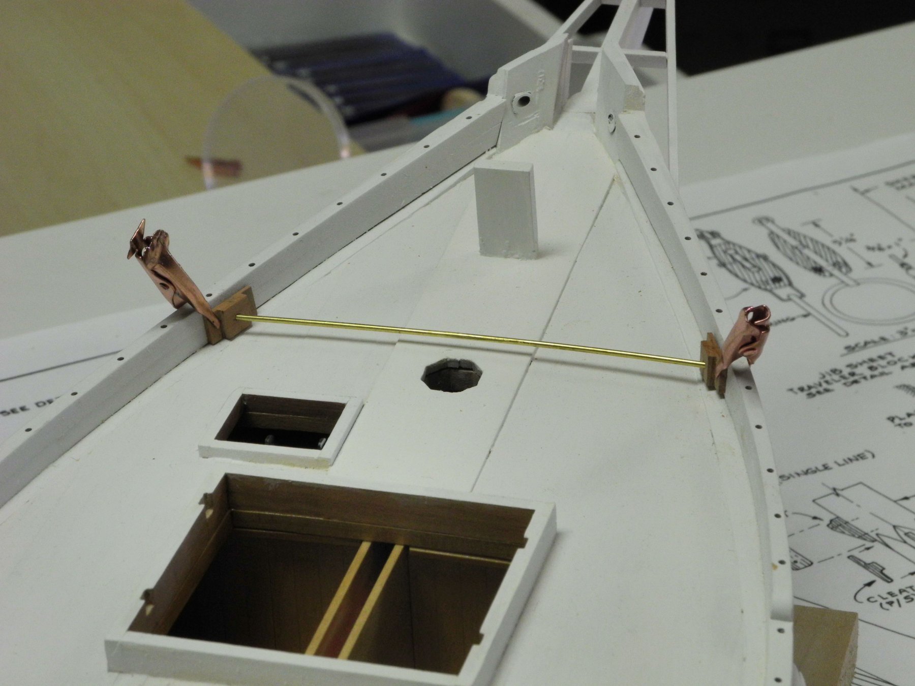
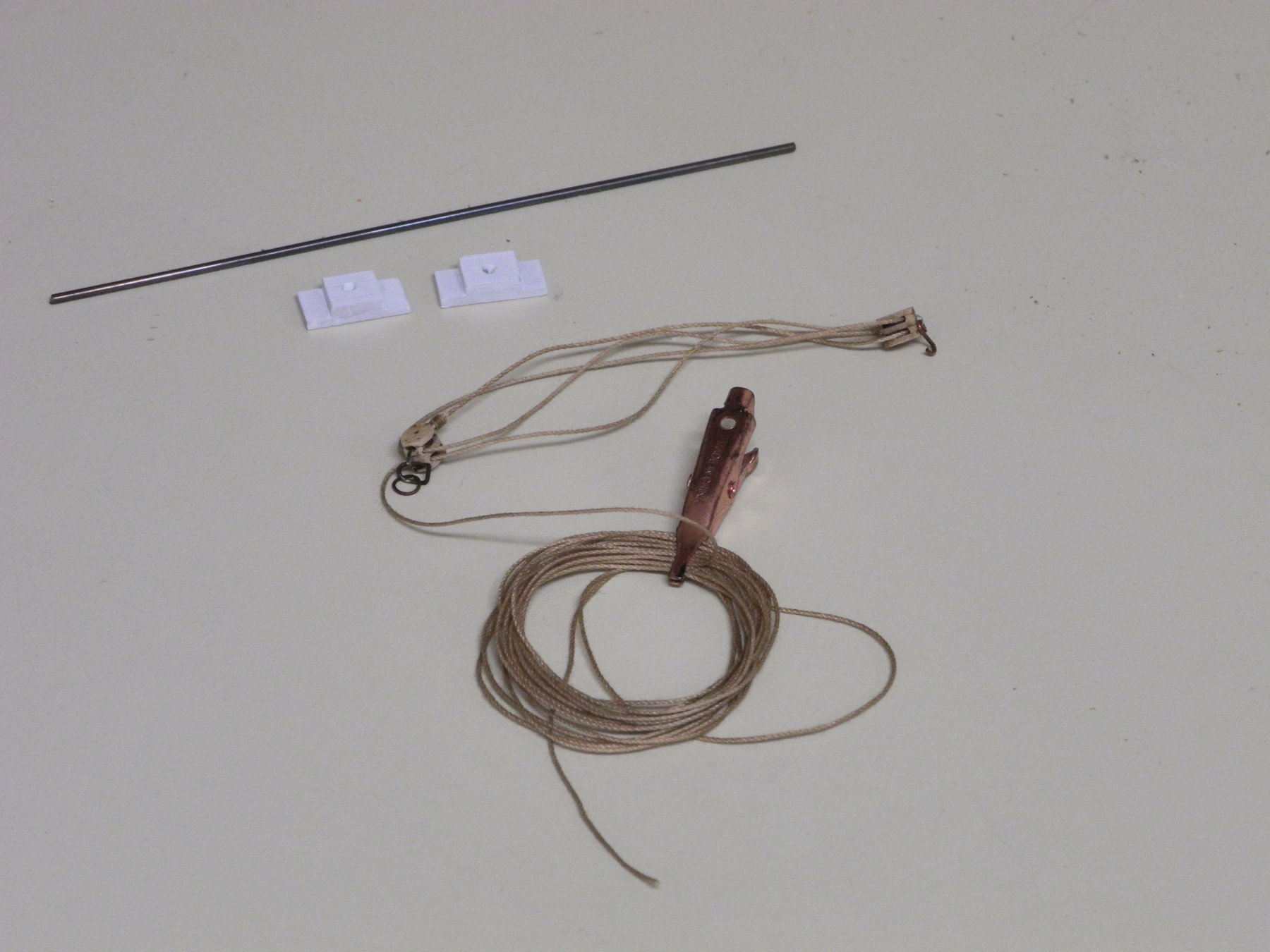
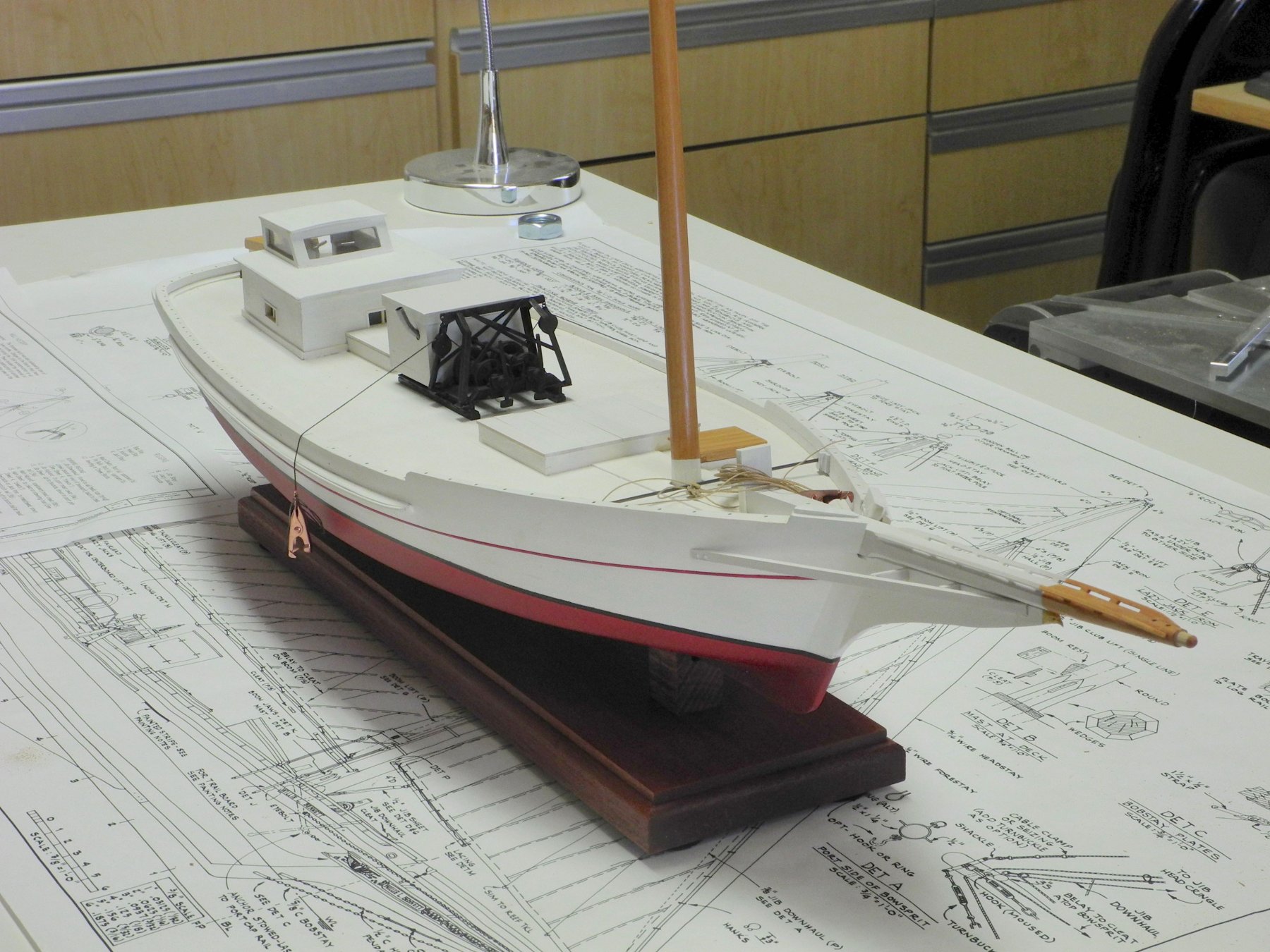
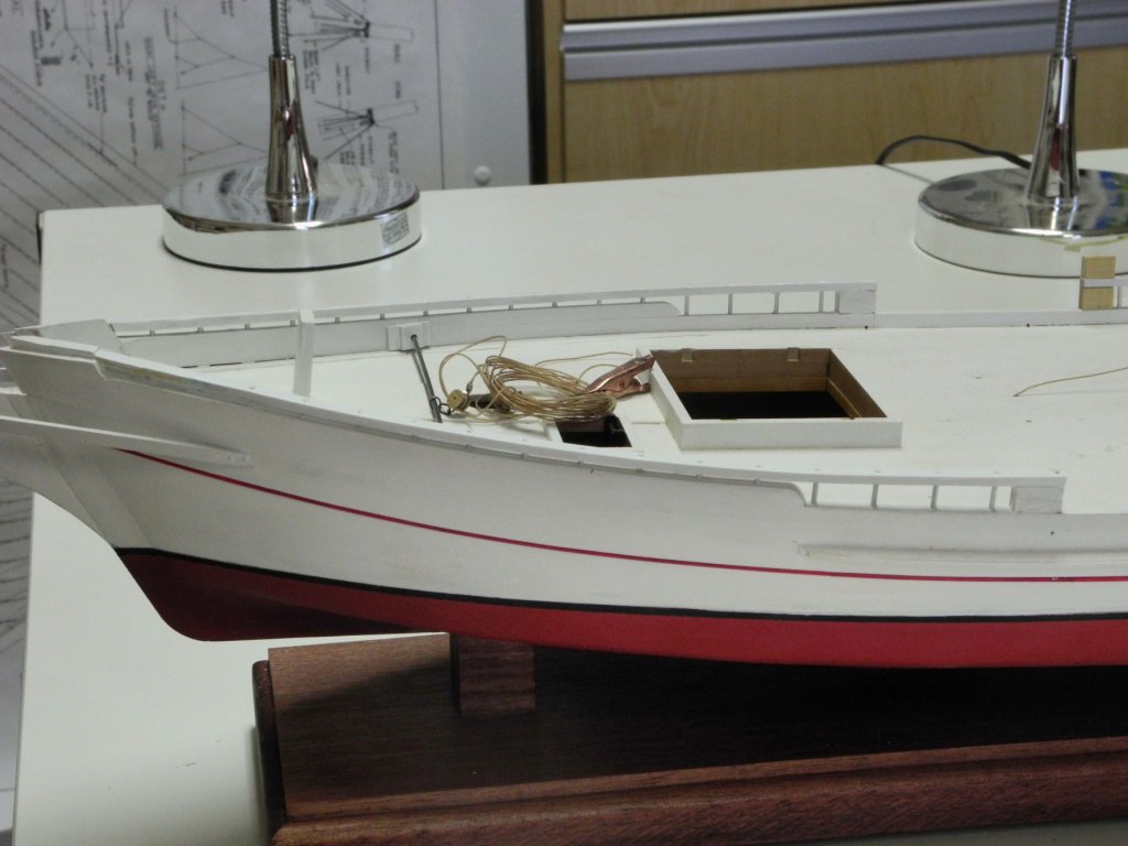
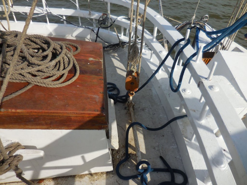
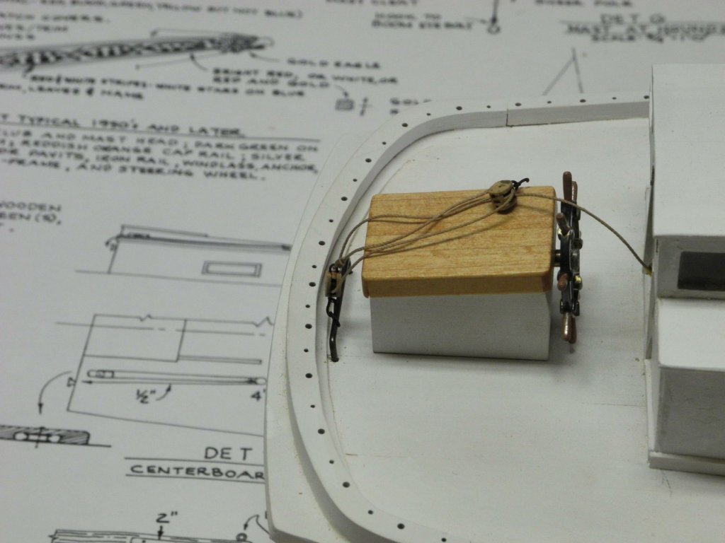
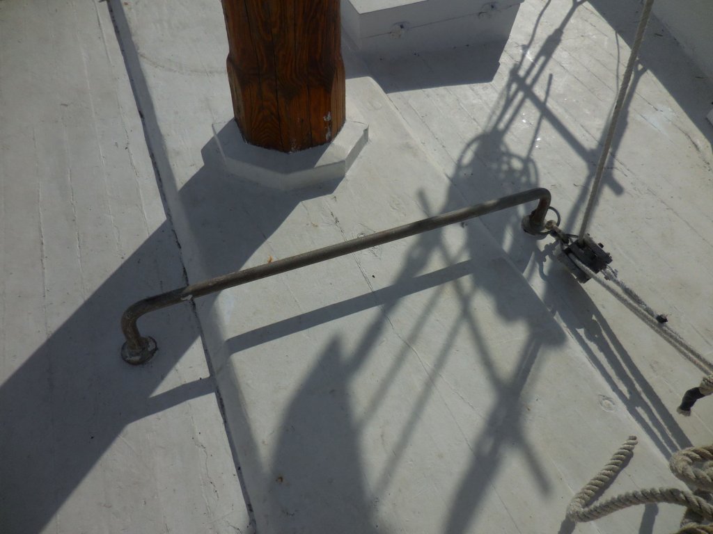
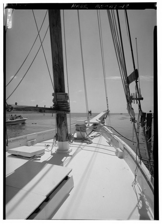
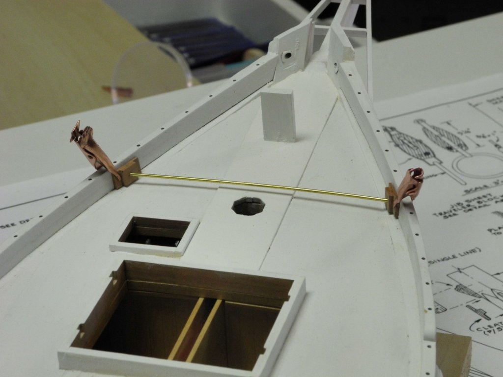
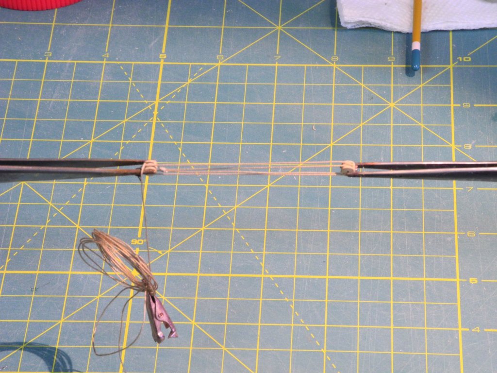
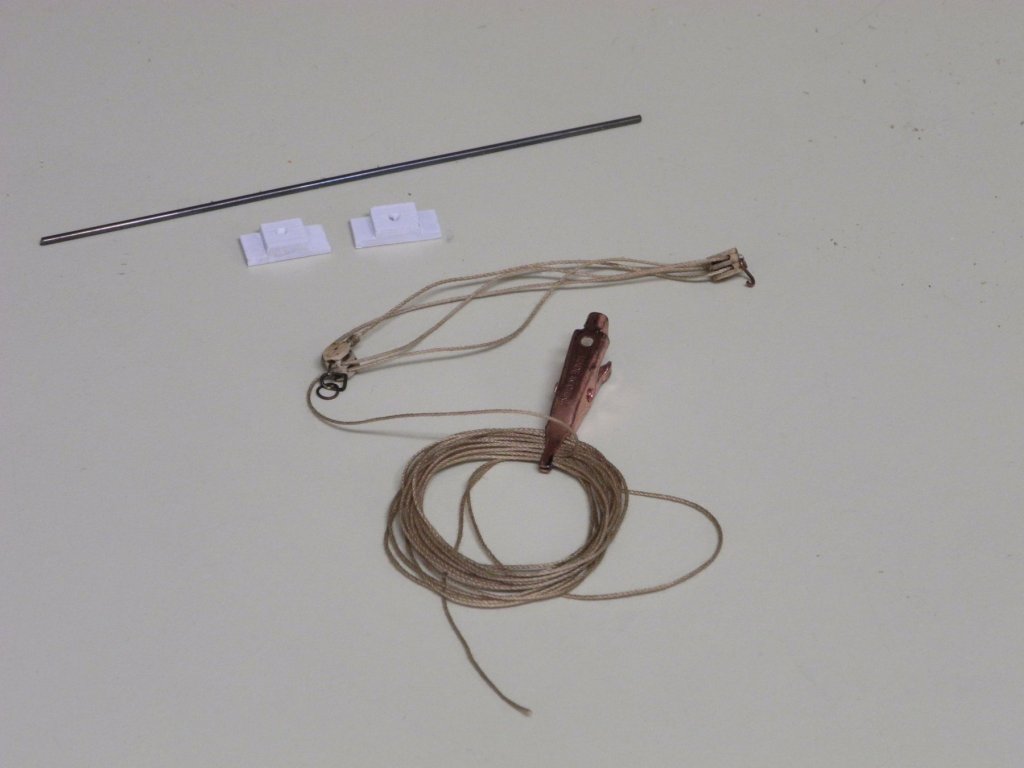
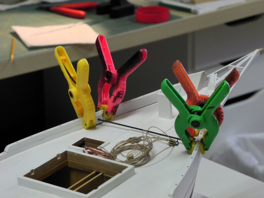
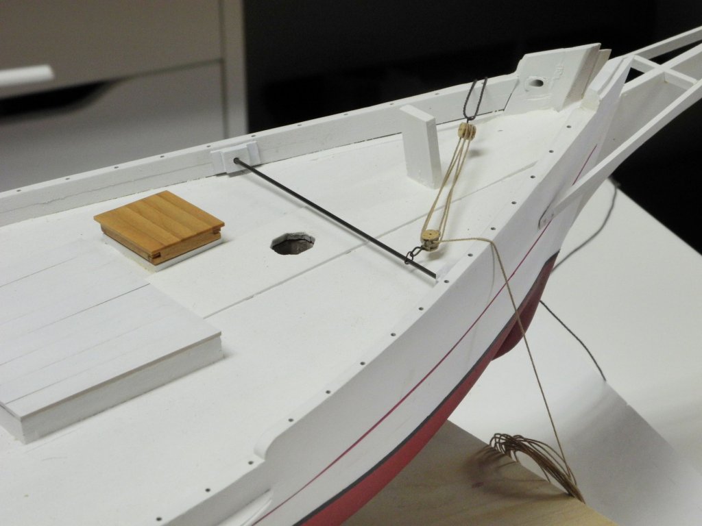
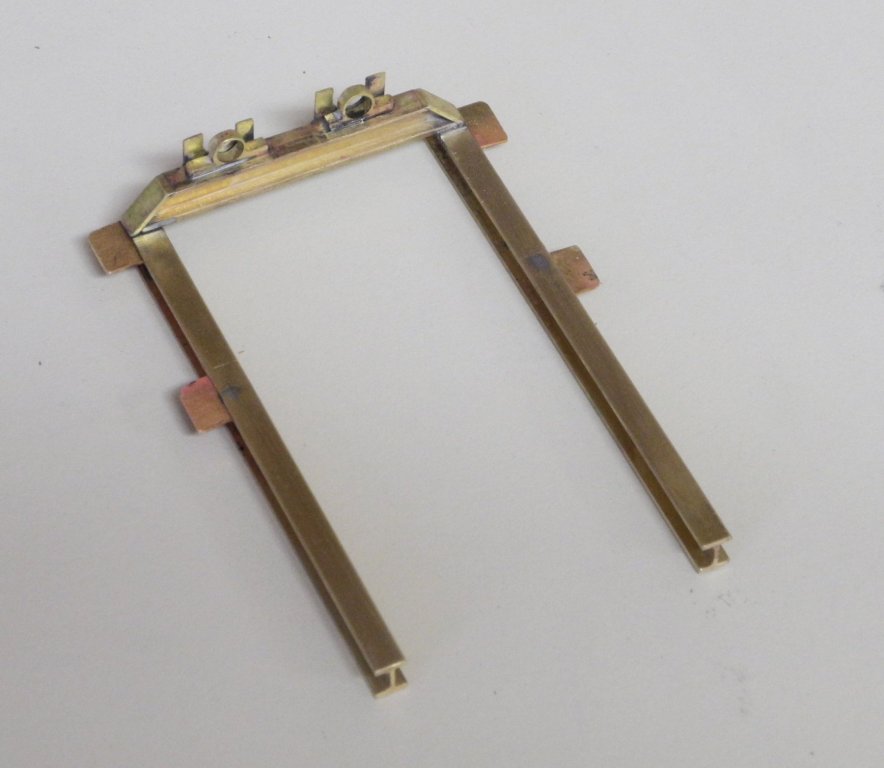
Part 53 – Pre-Rigging Work The next major activity in the Kathryn build will be the installation of the boat’s railings, which are fairly complex. They will also be somewhat delicate, so there are a few items that should be completed before the railing work begins. First is the Main Sheet Traveler. This is a 15” iron bar inserted as an inverted “U” just in front of the aft railings, as in the following photo. It makes a lot more sense to install this traveler before the railing installation. The rigging associated with the traveler needs to be completed before installation. There is a double block attached to the traveler by a ring and a shackle. On the other end, the sheet runs through a single block that will be hung from the boom by a hook that is attached to the block via a shackle. The loose length of the sheet is held on a cleat attached to the steering box. The blocks used are the ‘internally stropped’ blocks from Syren. These blocks look very similar to the blocks currently in use on Kathryn. The sheet was rigged through the blocks using the setup shown in the following photo. After rigging the blocks the traveler was run through the ring attached to the lower block. The traveler was then mounted through the deck planks in position behind the steering box. The large cleat for managing the sheet was made of wood and mounted on the steering box. The Jib Sheet Traveler has gone through some recent changes. The following photo shows the traveler as it is today, similar to the Main Sheet Traveler – an inverted “U”. However, at the time of the HAER survey the traveler was a bar that was mounted against the log rails on the bow sides. This configuration was still in place after the construction that was completed in 2015, as shown in the following photo from that time. The traveler on the model is configured as it was during the HAER survey. The following photo shows the brass rod used for the traveler temporarily held in place by the mounting blocks for the traveller. The Jib Sheet is rigged using two double blocks. From the deck level the sheet will be run through a block at the hounds and then back down to a cleat near the deck level, so a generous amount of rope was used for the sheet and coiled onto the deck for later use. The work setup for this rigging was the same as for the Main Sheet. The traveler was installed by clamping the mounting blocks while the glue cured. (Any gluing that needed to be done over a painted surface was performed using Weldbond PVA, which provides a strong bond even on a painted surface.) At this point in the construction it was also a good idea to mount the model on its permanent base, since waiting any longer for mounting would present a risk to the delicate work that will be done next. There are a couple of other minor items that I wanted to get out of the way before working on the railings, but I’ve wasted a few days trying to make some very small components and have decided to put that aside for later and to begin installation of the railings, which will be the topic of the next post. Thanks everyone!


- 878 replies
-
- 18
-
-
Thanks everyone for the 'Likes' and comments. It feels good to be back to work on Kathryn.
-
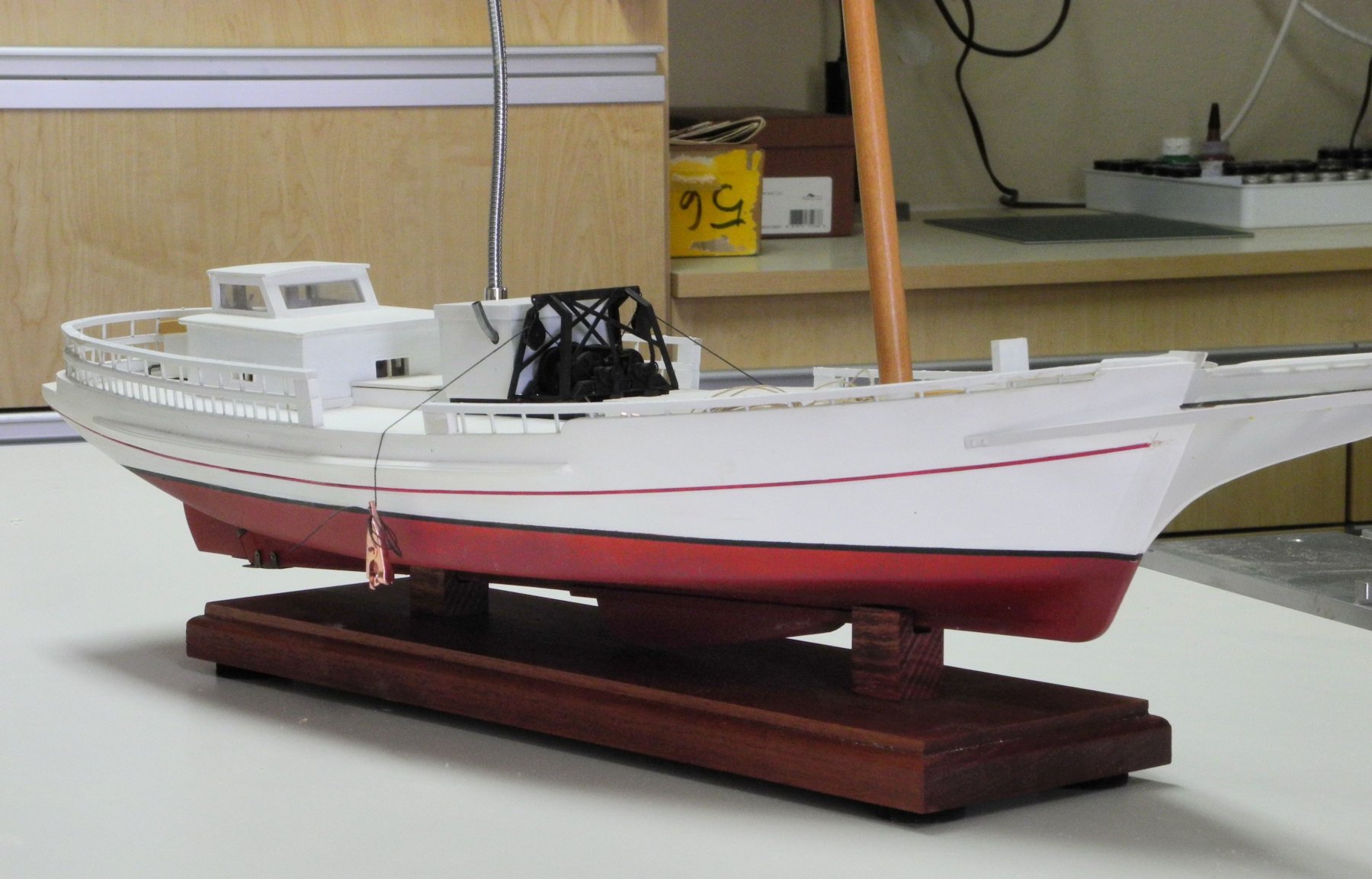
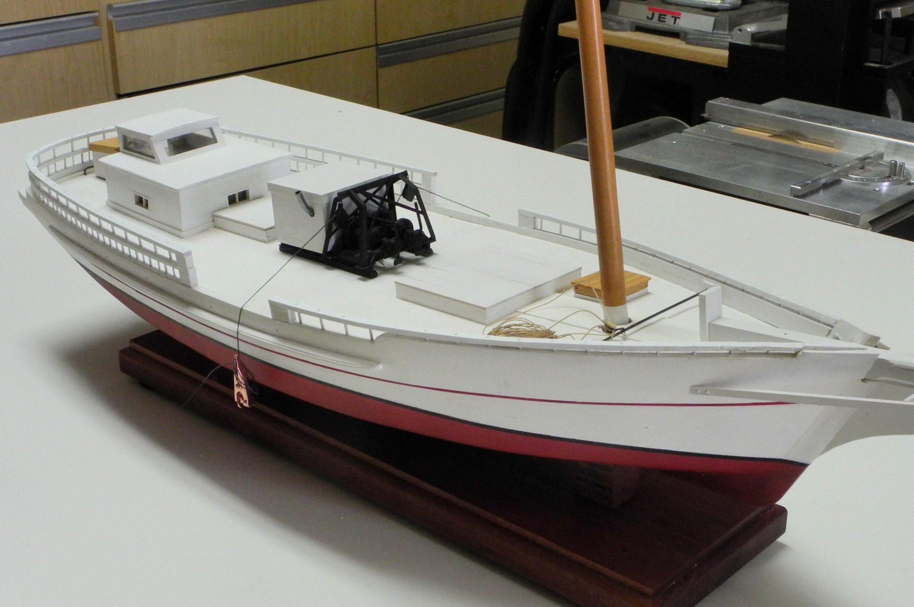
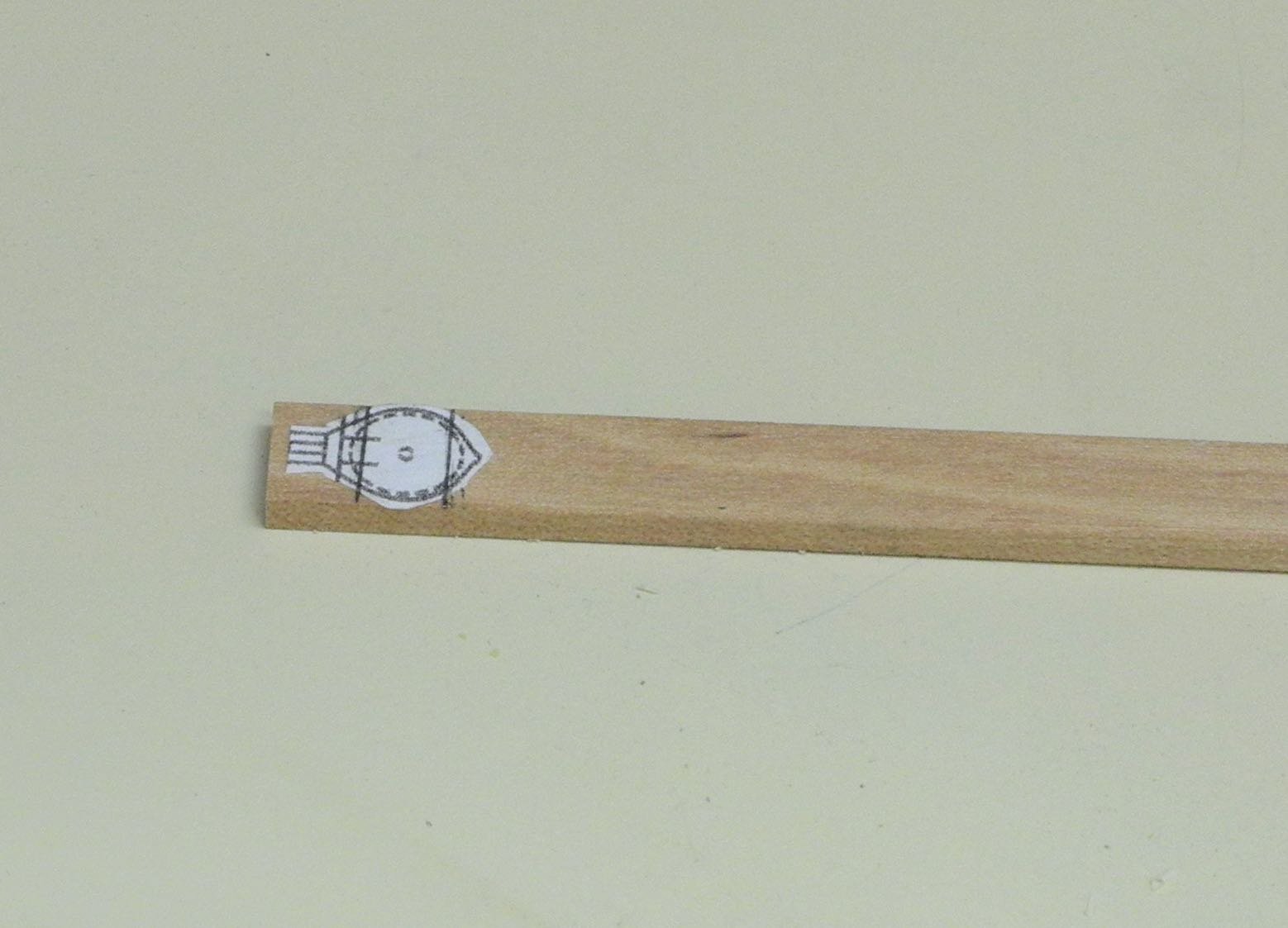
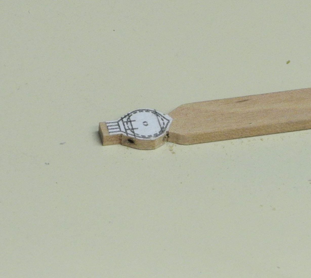
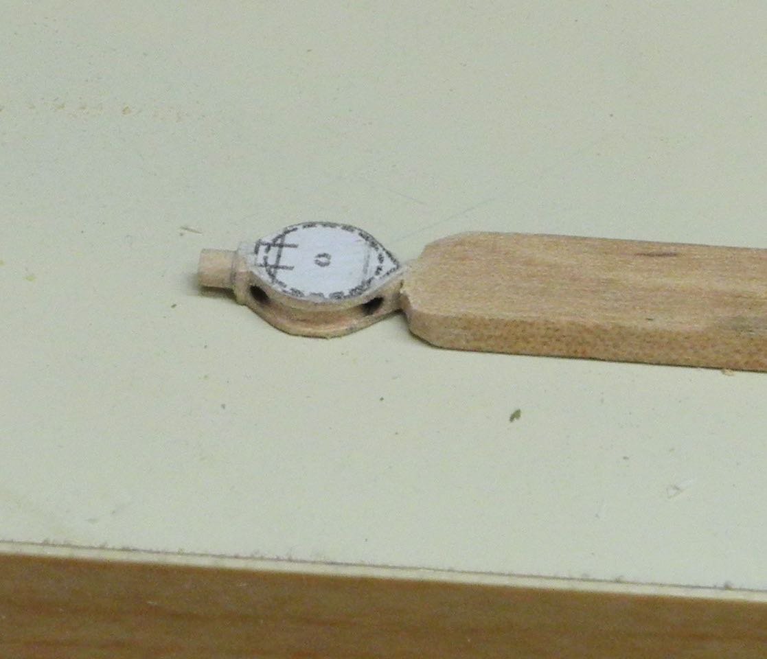
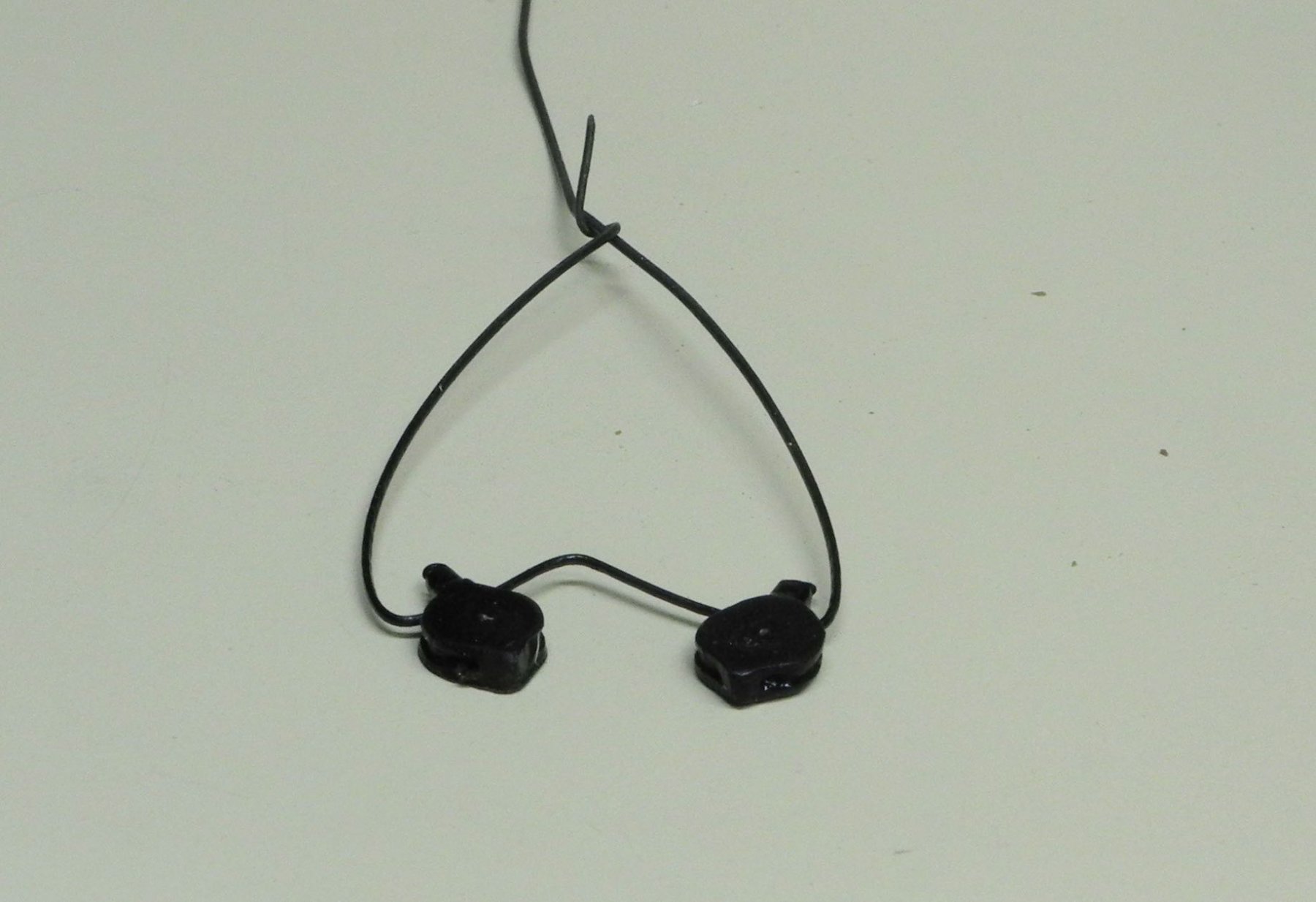
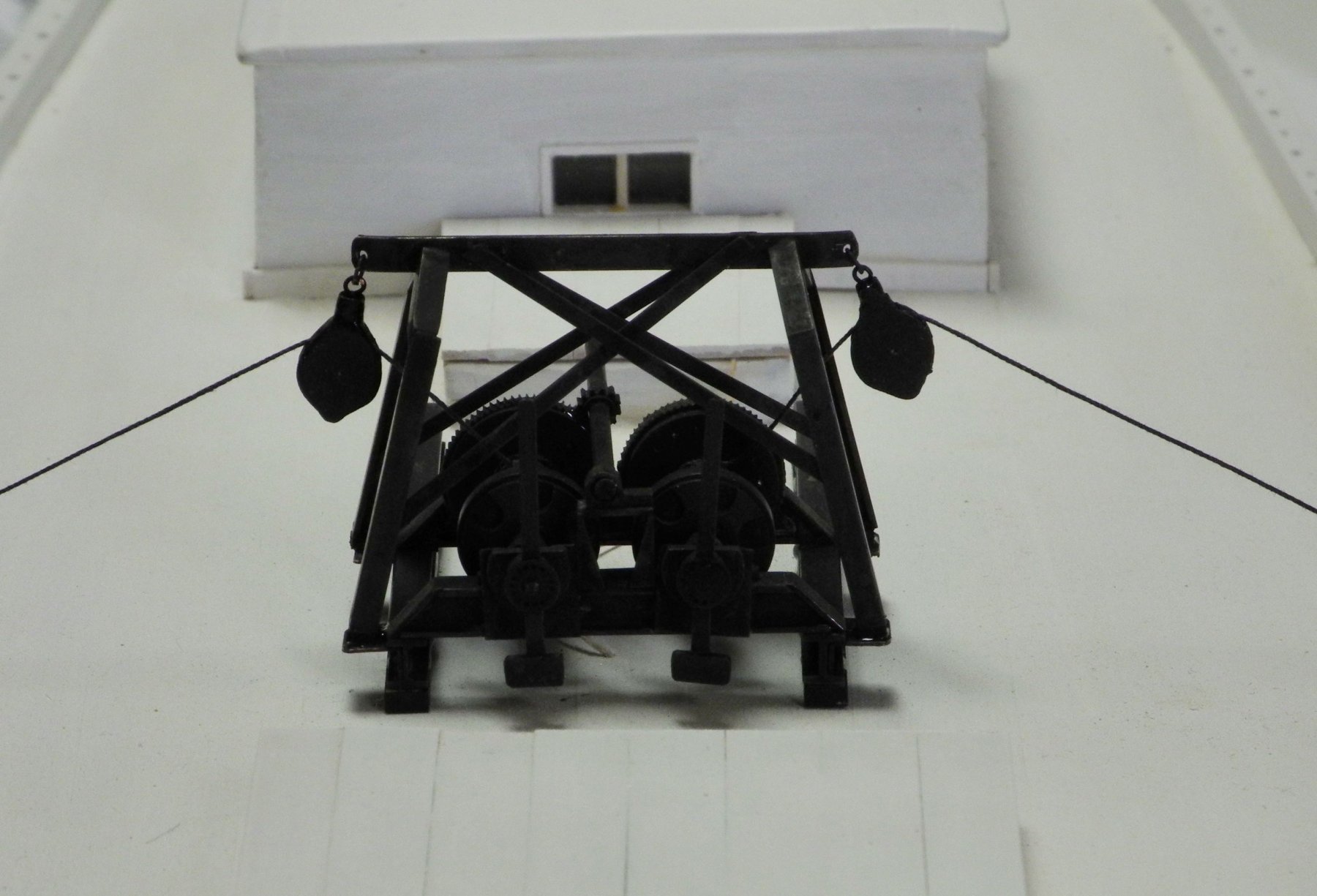
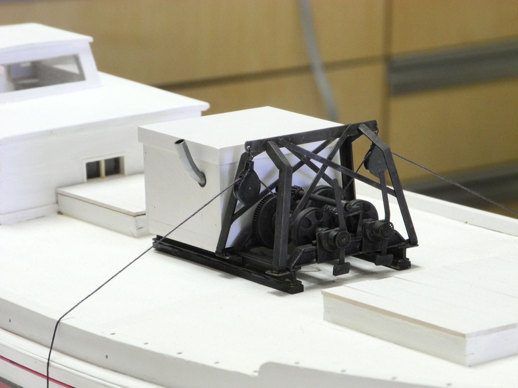
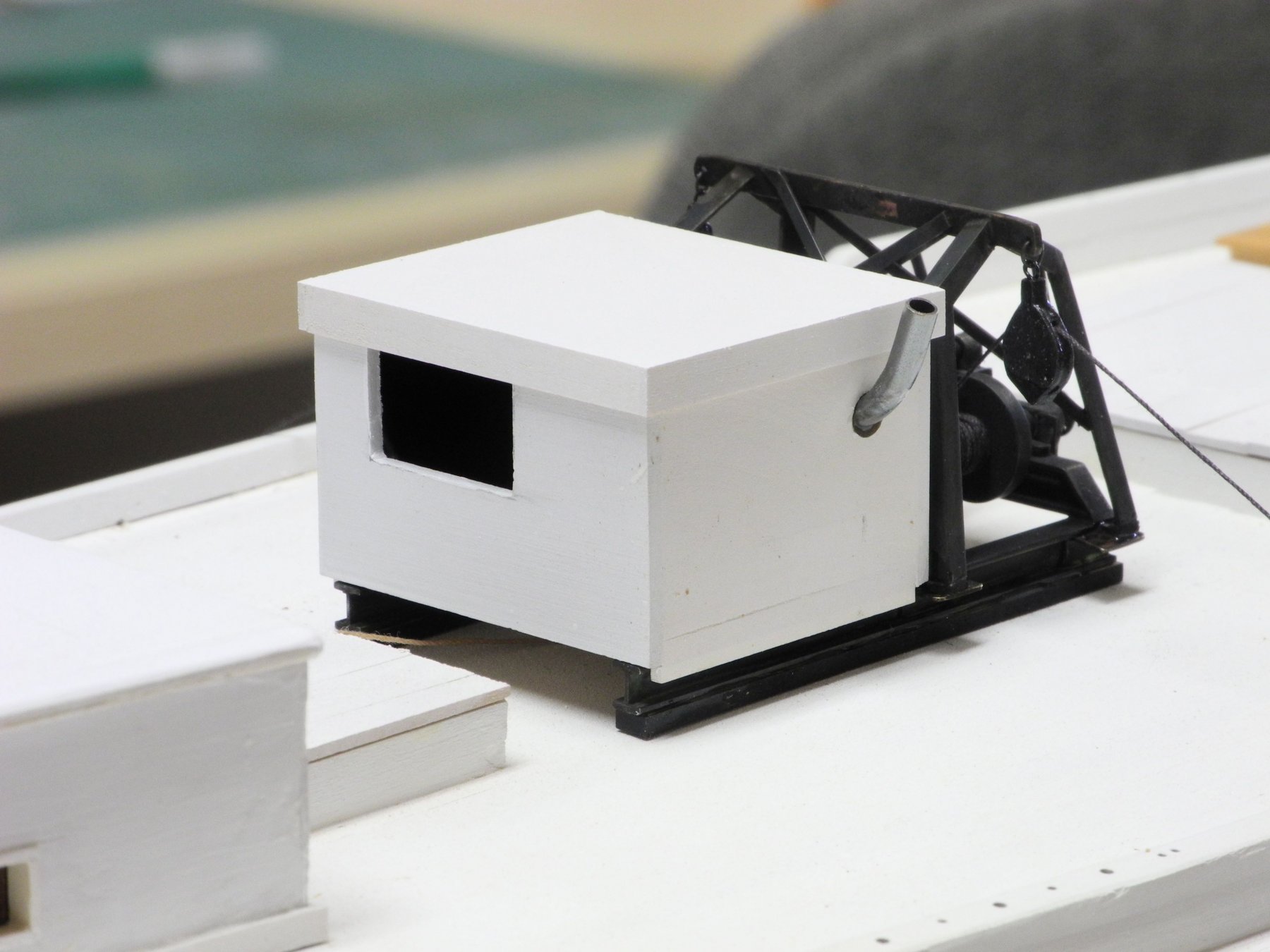
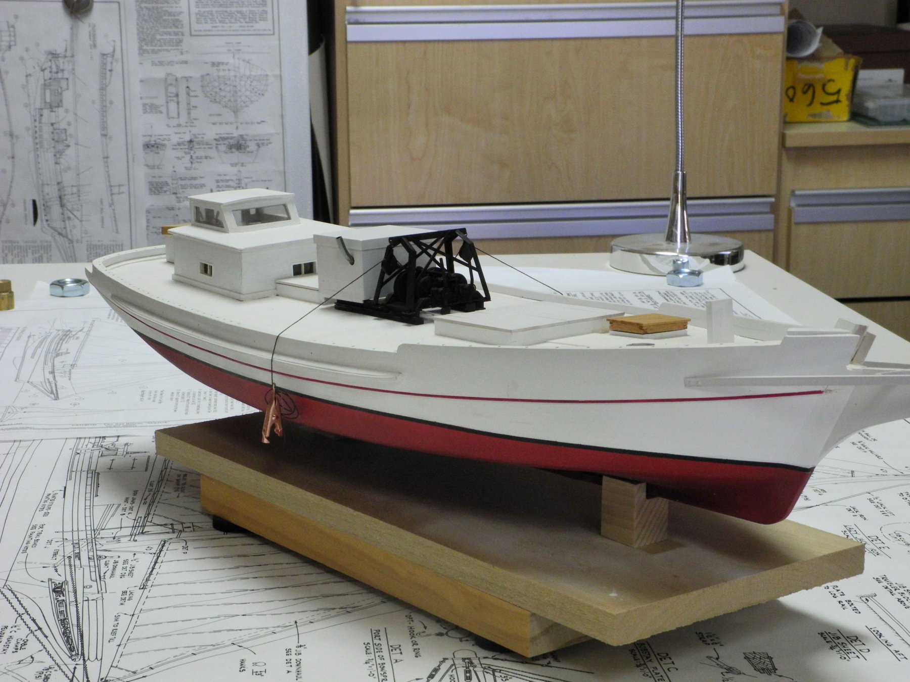
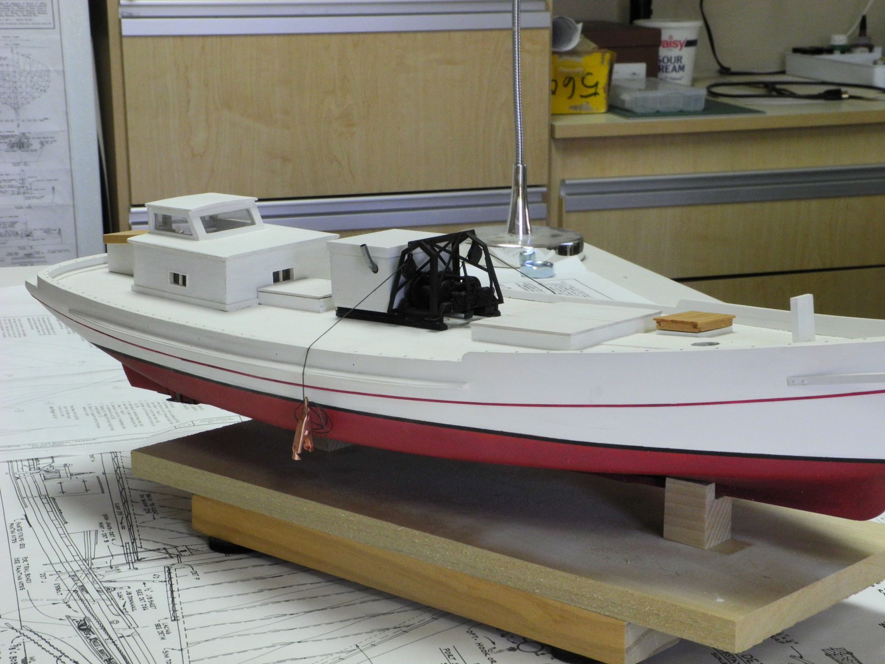
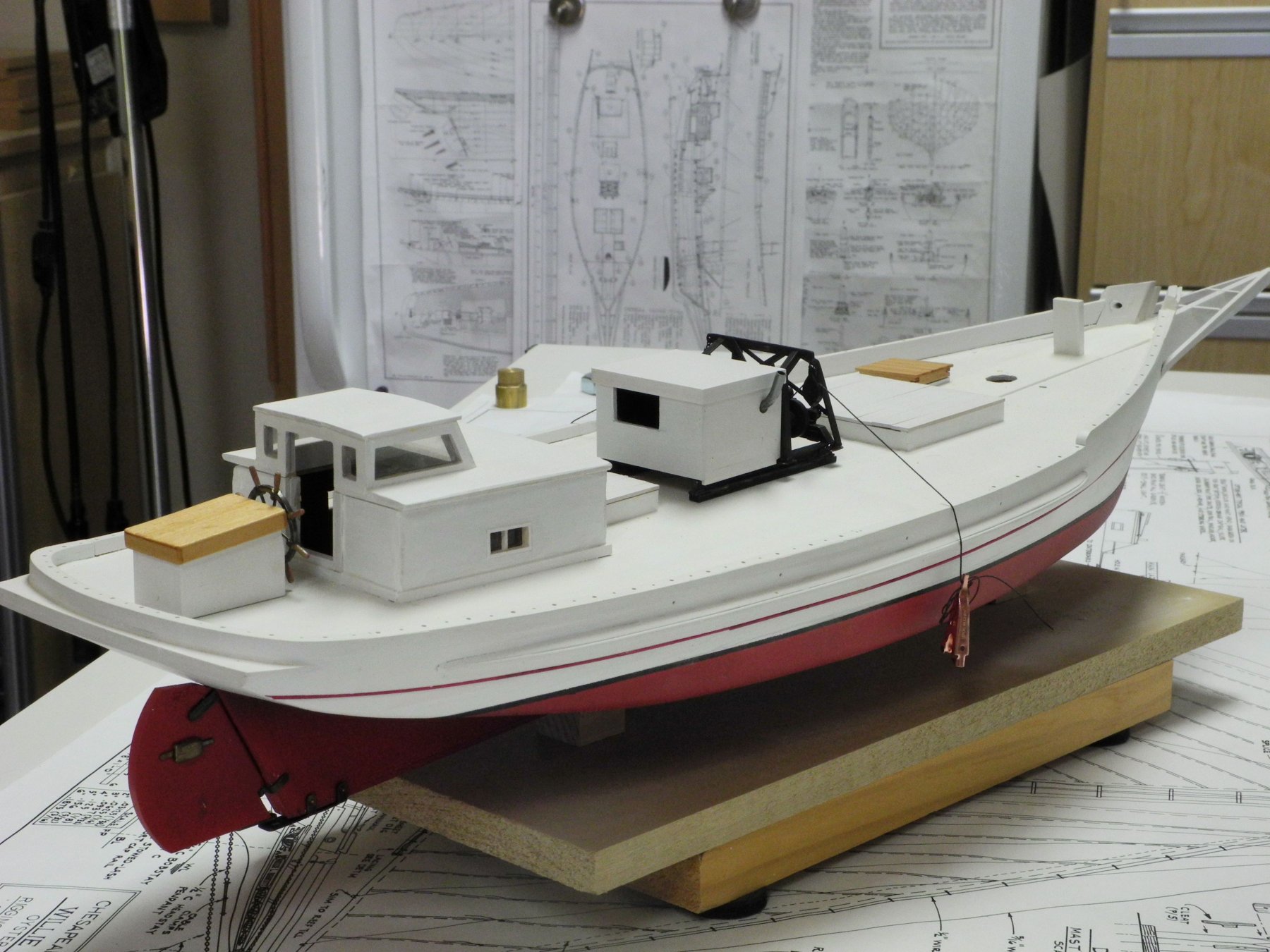
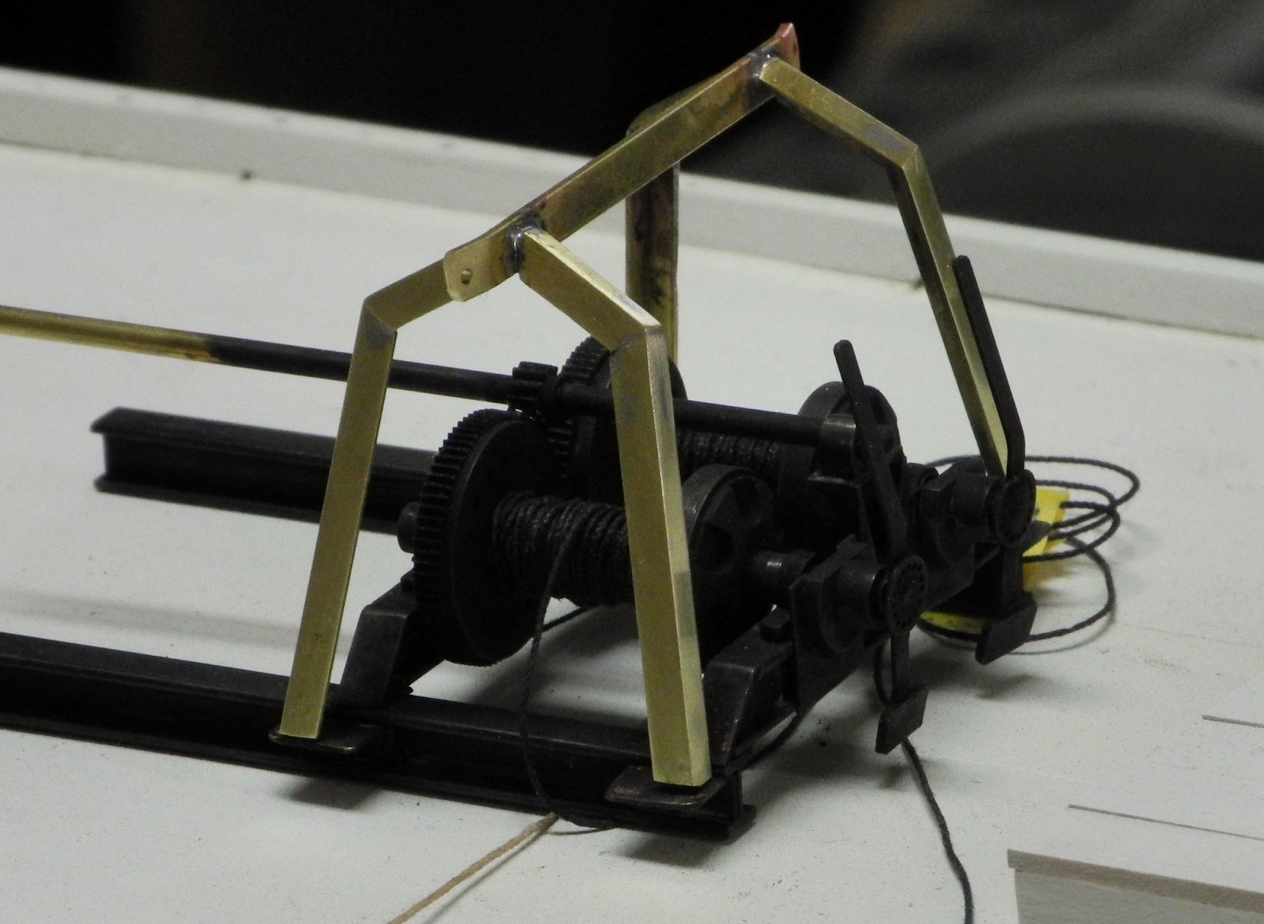
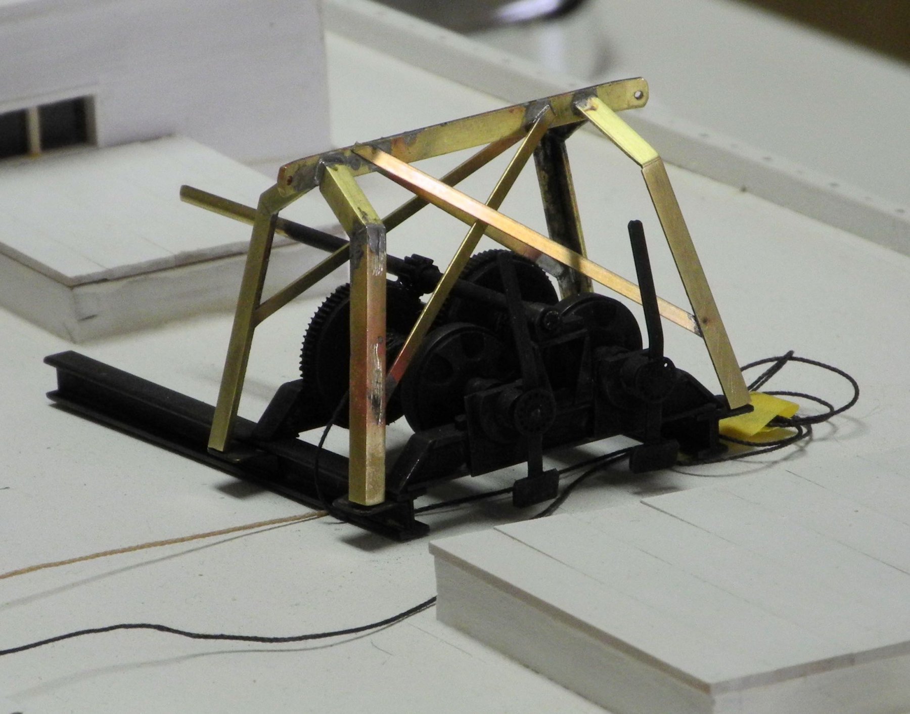
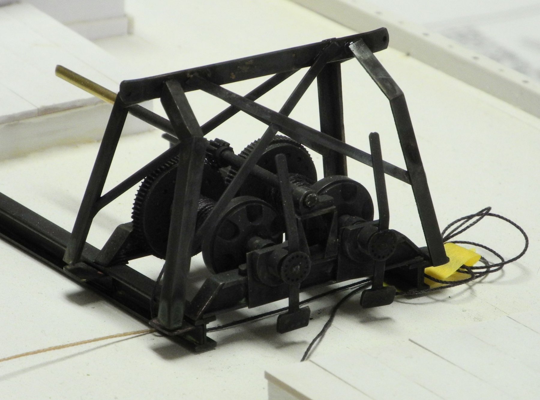
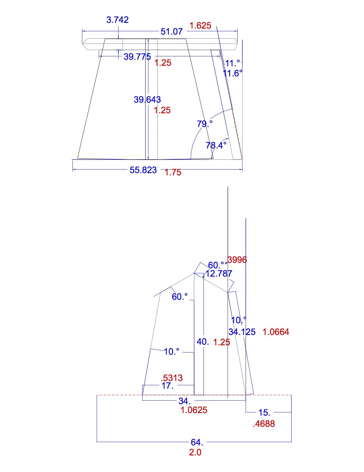
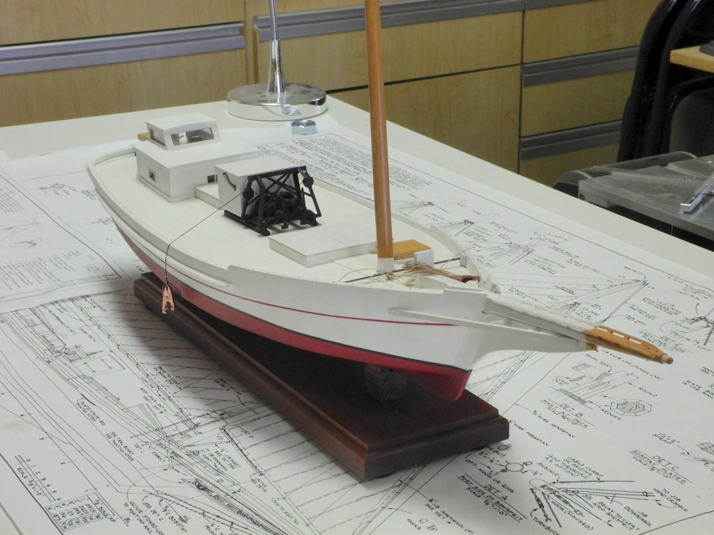
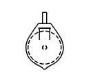
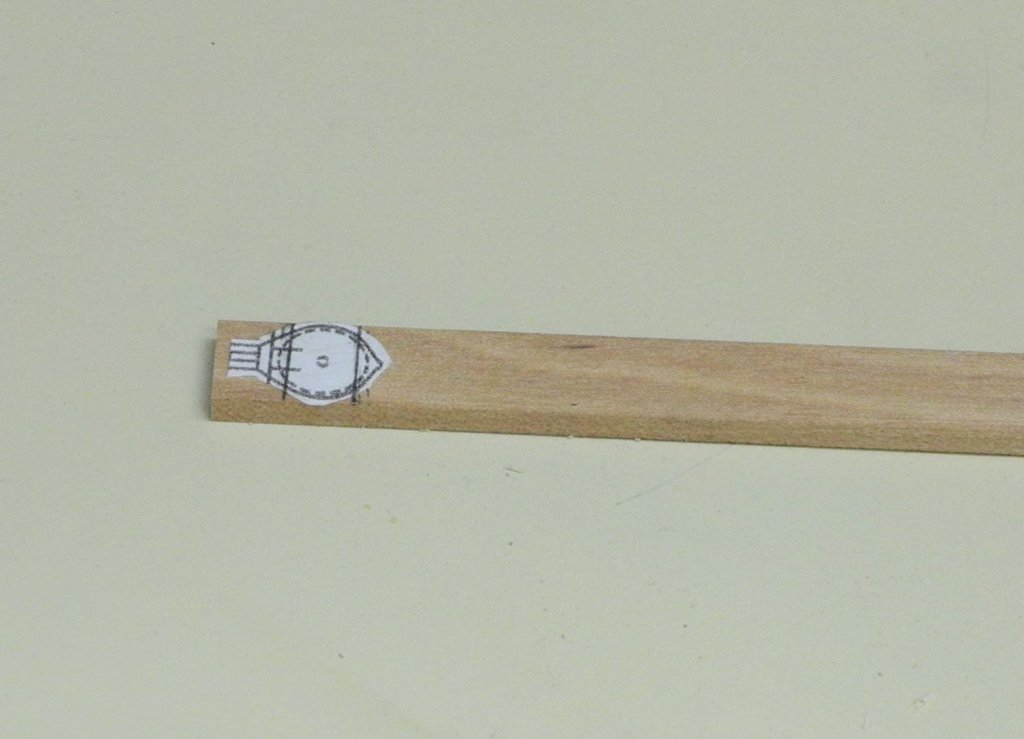
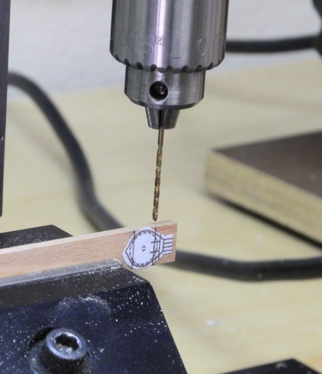
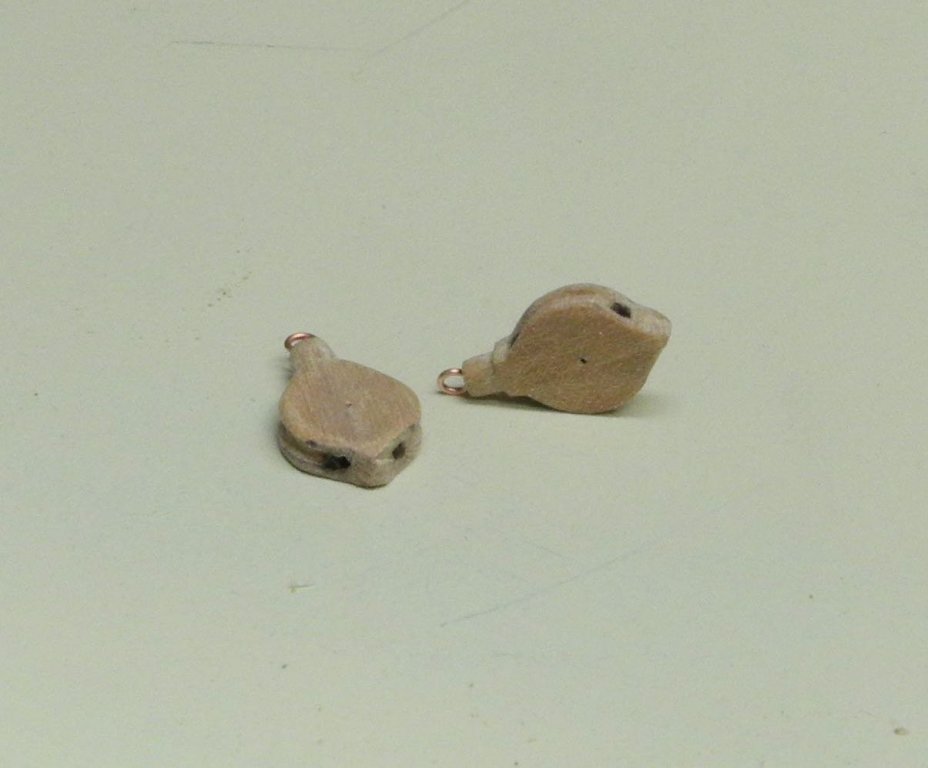
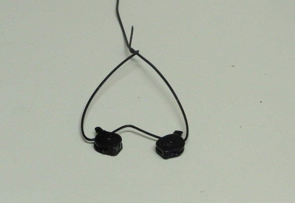
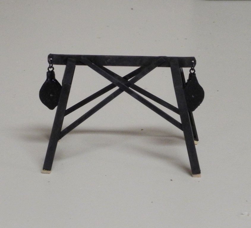
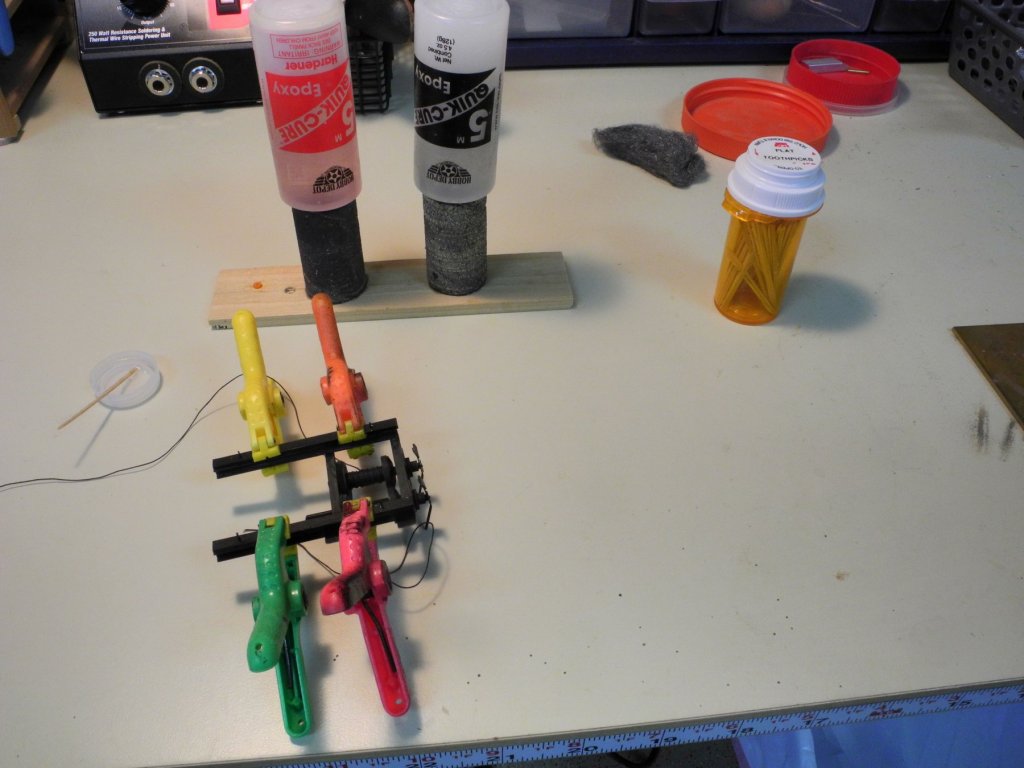
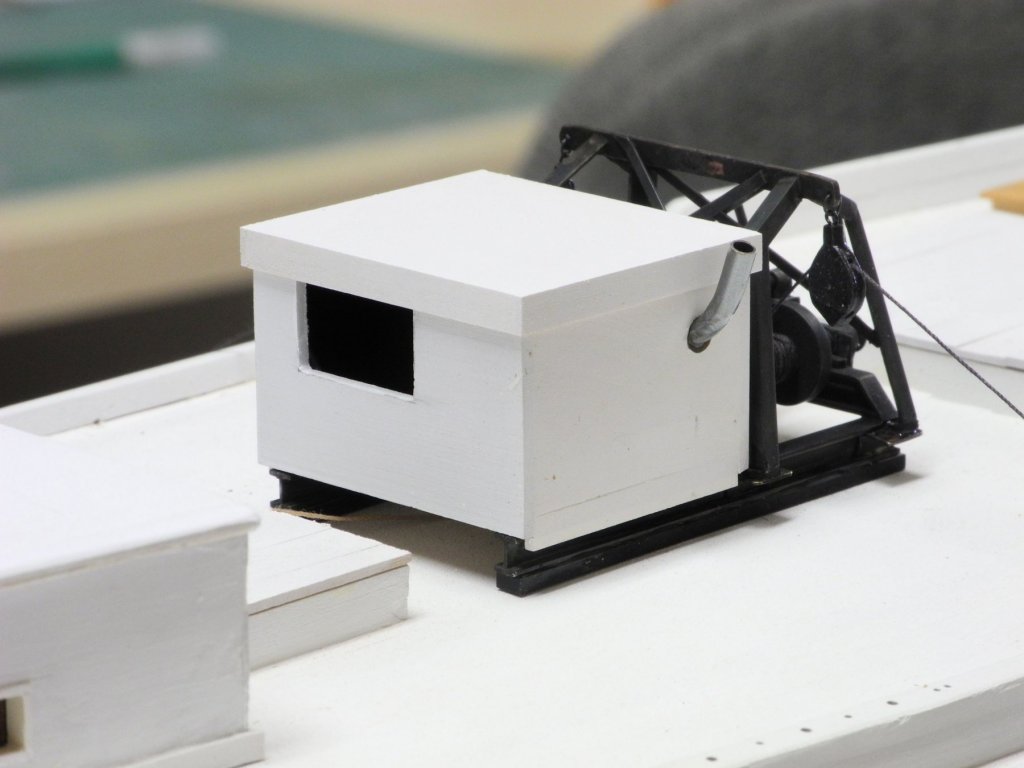
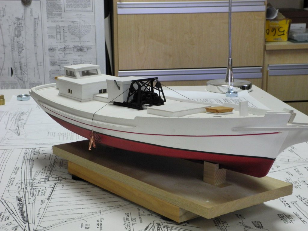
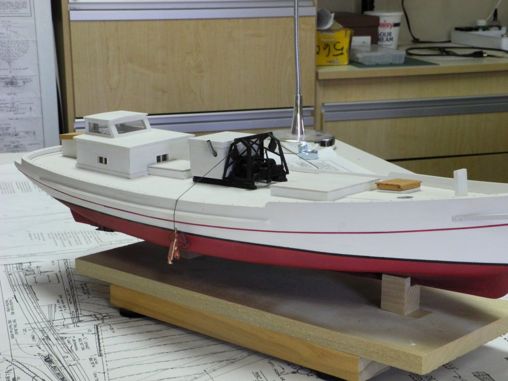
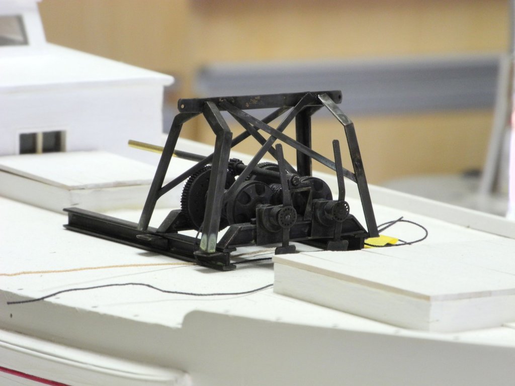
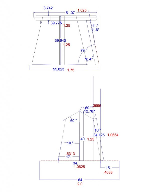
Part 52 – Kathryn’s Dredge Winder Cont’d There are two pulleys hanging off either end of the dredge winder’s crossbar. The shape of these pulleys is fairly unique, so available blocks couldn’t be used and they needed to be fabricated. The following drawing shows the shape of these pulleys. I tried making these out of brass, but the small size presented lots of problems so I decided to make them out of wood. The first step was gluing the drawing to an appropriately sized piece of wood. The holes representing the size of the sheaves were drilled. Then the outline of the pulley was shaped, first by cutting on the scroll saw and then by finishing with small files. The groove representing the outside of the sheave was made using a small round escapement file. A hole was drilled in the top of the pulley and a small ring made from copper wire was inserted and glued using CA. The pulleys were hardened by soaking with thin CA, and were then finish-sanded. Black Rust-Oleum paint was sprayed on the pulleys while they were held by thin wire. The pulleys were attached to the crossbar using small rings made from black wire. The I-beams supporting Kathryn’s dredge winder are themselves supported by some wooden planks. On the model, these planks were drilled and then small pieces of .019 piano wire were glued into the holes to act as pegs for attaching the winder configuration to the model’s deck. The planks with pegs were epoxied to the bottom of the I-beams. The blackening was scraped off the I-beams to ensure that the epoxy would hold. Holes were drilled into the model’s deck to take the pegs. The following photo shows the winder configuration pegged to the deck, with the ‘cables’ for the dredge winders fed through the new pulleys. The dredge winder is powered by a V-6 Buick engine contained in an engine housing. The following photos show the model’s engine housing in place. The exhaust pipe was made from 1/8” brass tubing colored with JAX Flemish Black diluted 1:1. The dredge winder assembly will not be permanently mounted on the model until somewhat later in the build. Here are some photos of Kathryn’s current state. There are a number of small items to be completed next, while I spend some time planning for the rest of the build. Thanks everyone!


- 878 replies
-
- 25
-
-
That's another radical design! I'll be interested to see how you pull off the forward railing at your scale.
-
Hi Patrick I’m continually amazed at how much detail you can get into a tiny space. The little tender is awesome. (And I’m sure your garden is equally impressive - what scale is it?). 😉
-
Thanks everyone for the likes and comments. Ed - I use 62/36/2 Silver-Bearing Solder from Radio Shack. It's .015" diameter wire, so I can cut very small pieces. I also use Stay-Clean liquid flux. The blackening of the winder was done with JAX Chemical's 'Pewter Black'. Most of the other metal components will be blackened with their "Brown Black" product, which gives a warmer black and won't be as stark. In the photos of Kathryn (and in real life) the blackness of the winder is striking, while the other components not so much. The winder was painted with Rust-Oleum gloss black the last time I saw it. I used the JAX Flemish Grey-Black, very diluted, on Kathryn's wheel and will likely use that in some diluted form where appropriate. Patrick - thanks for the compliments, but the super-miniature work you do is already outstanding - so your skills and talent are already 110%!
- 878 replies
-
- 11
-
-
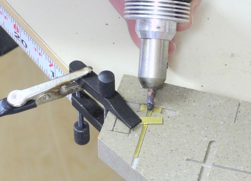
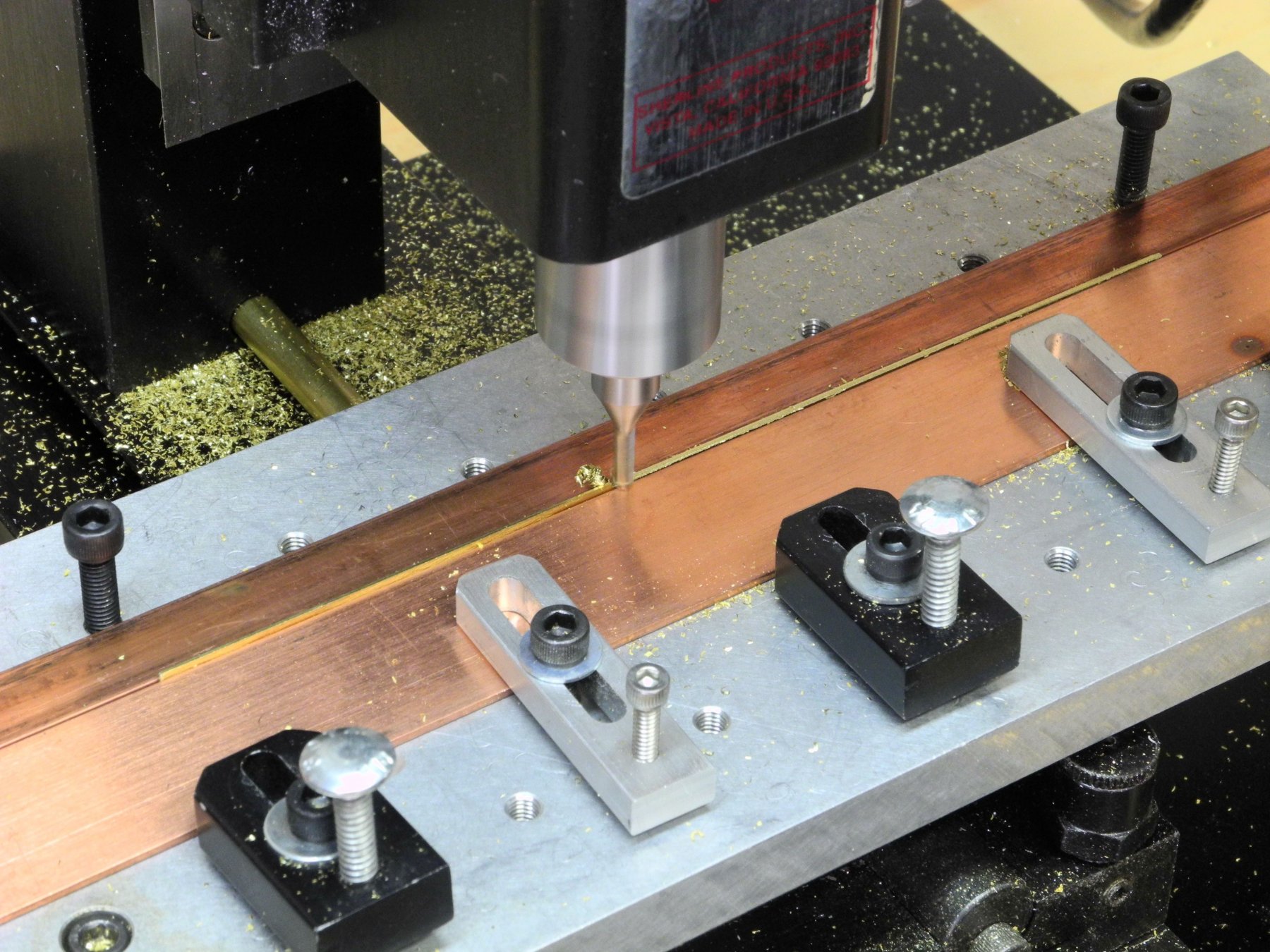
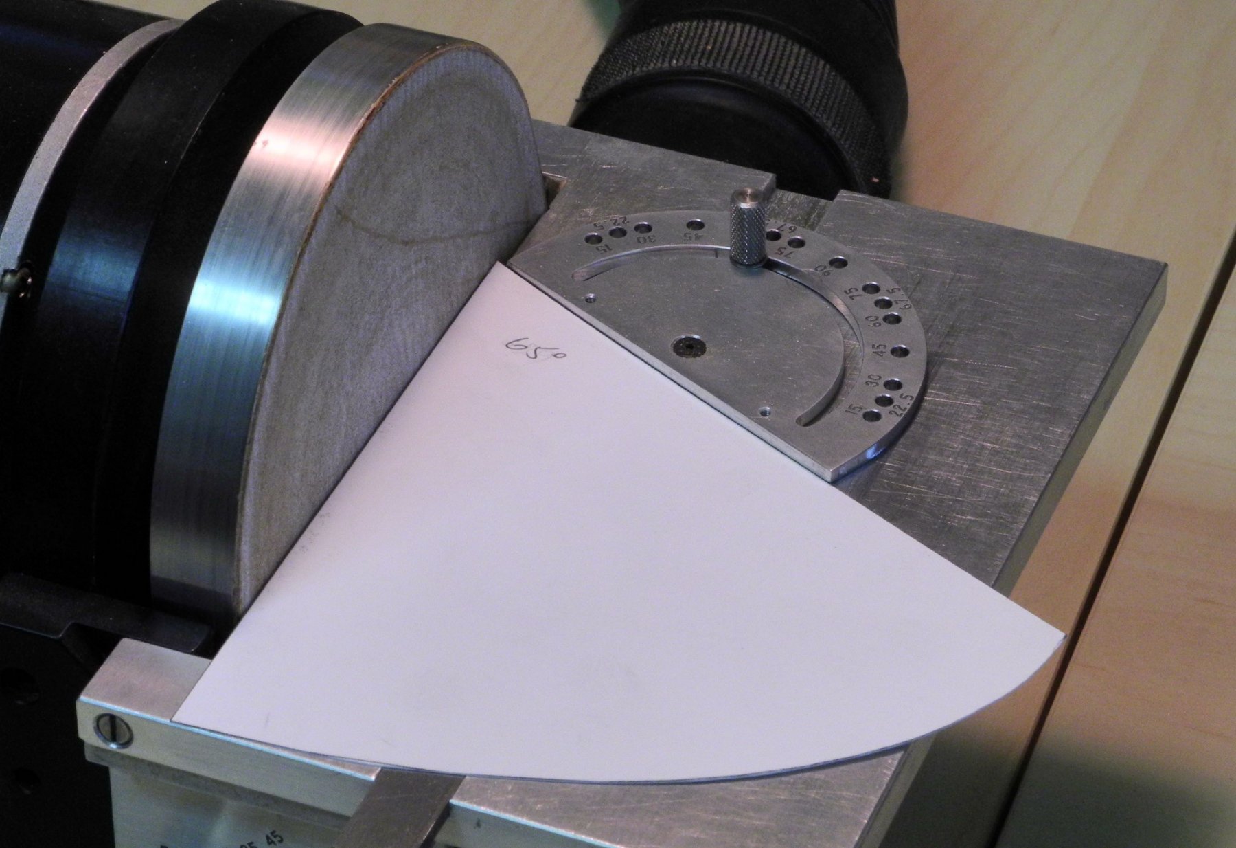
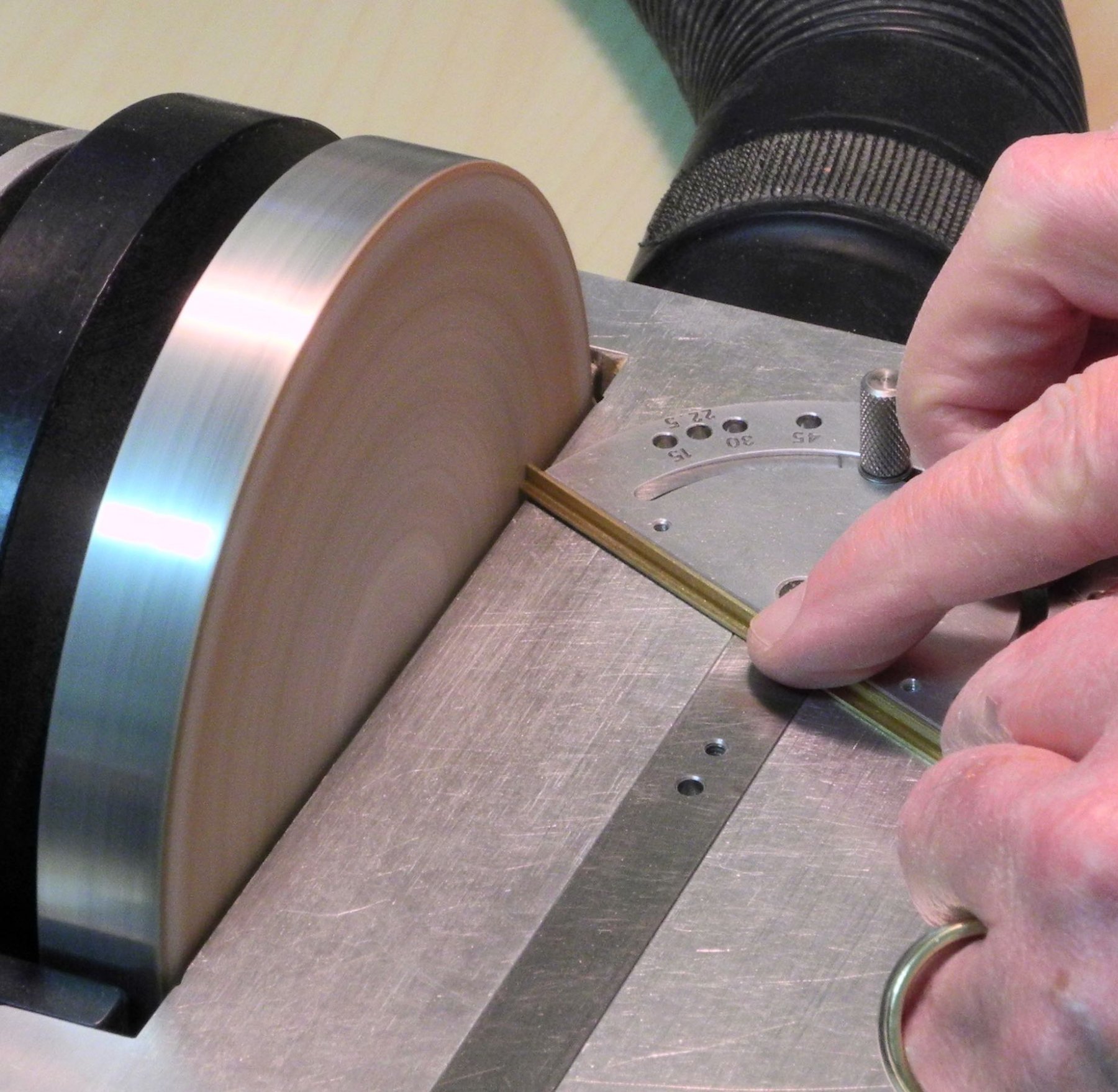
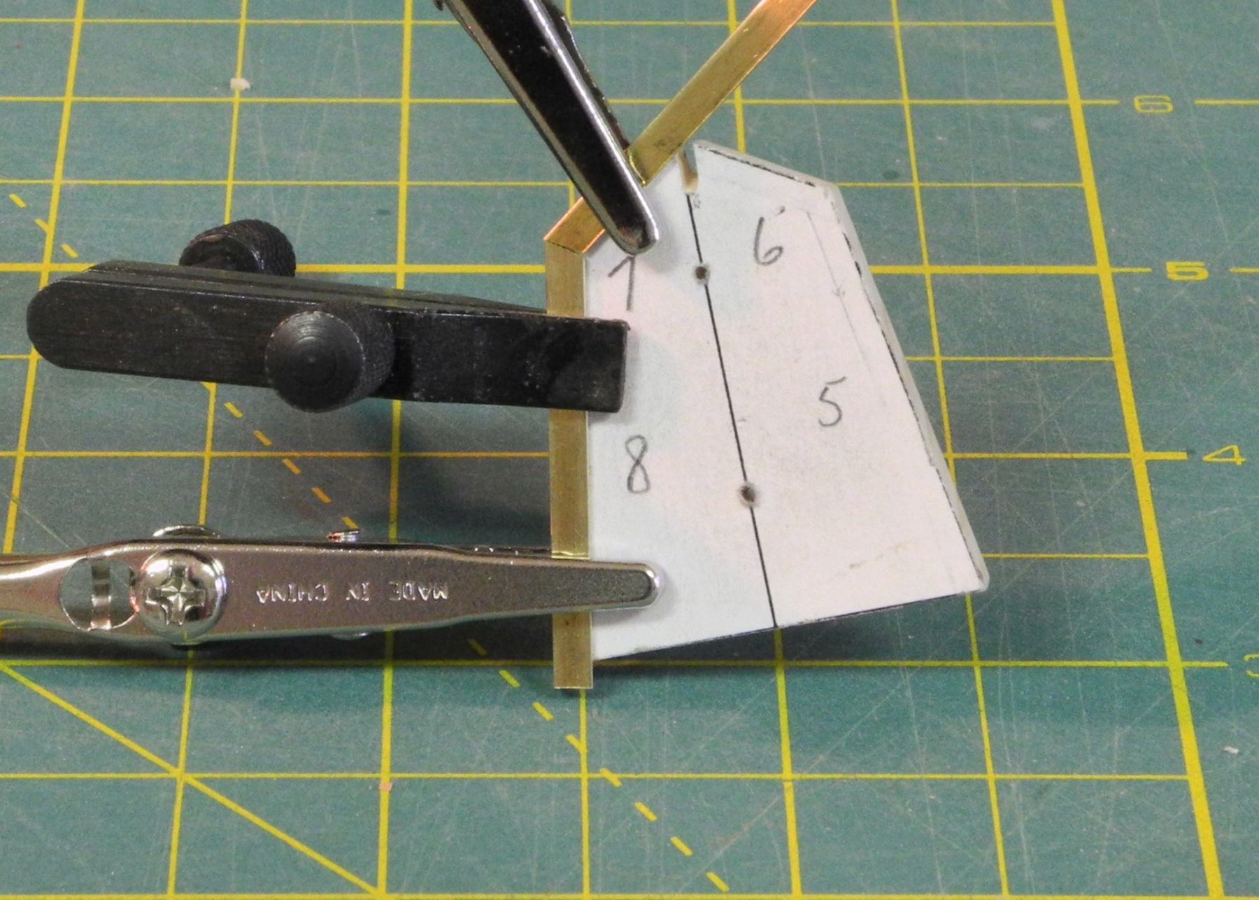
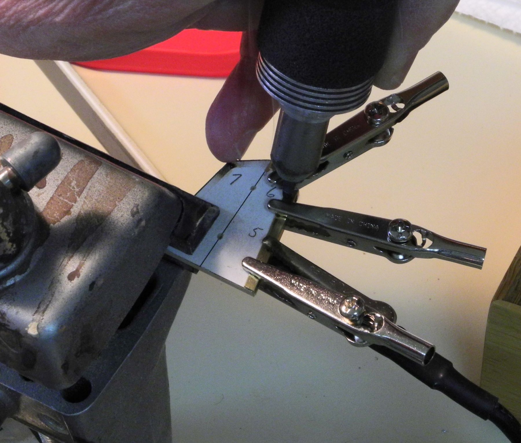
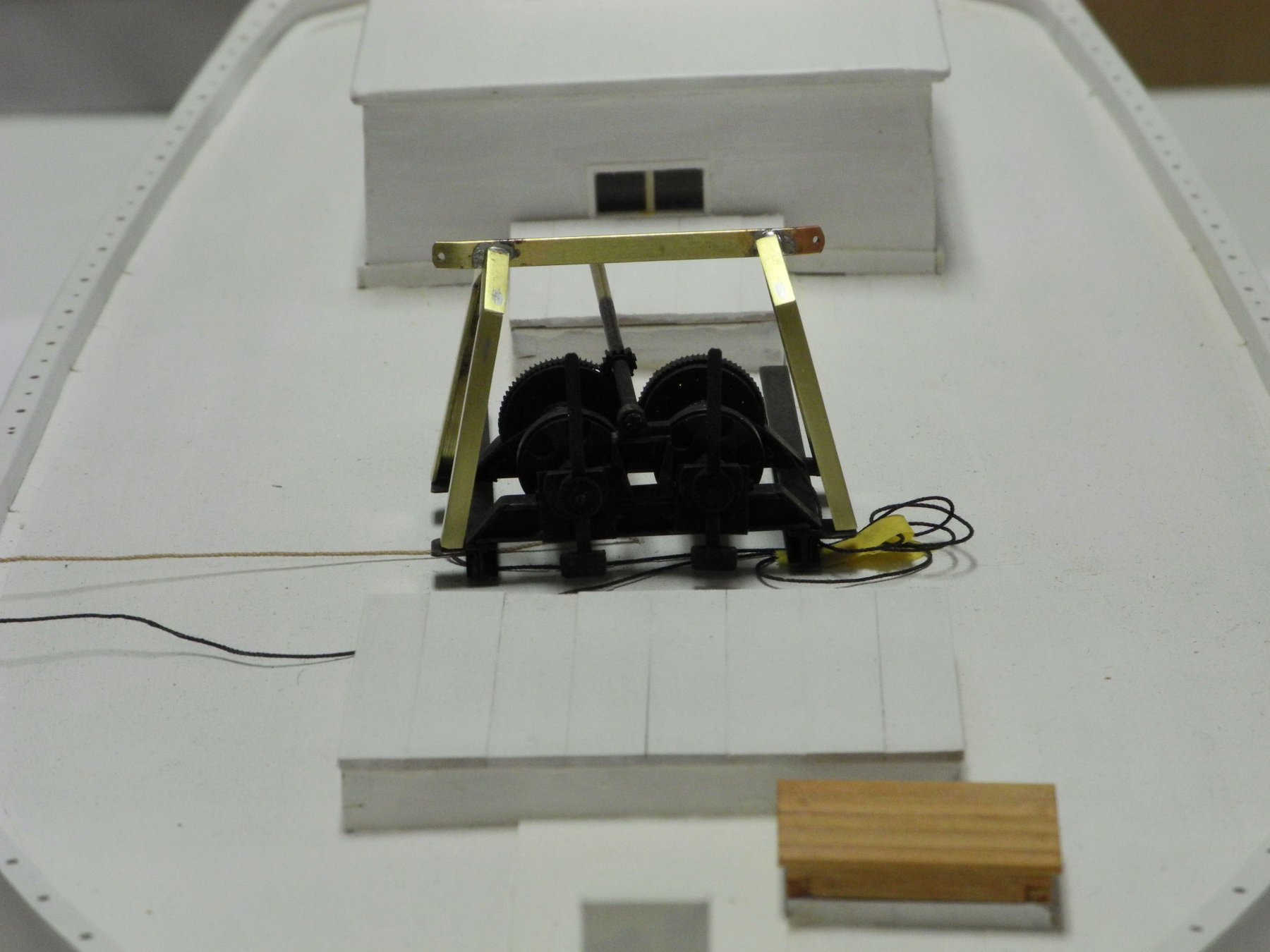
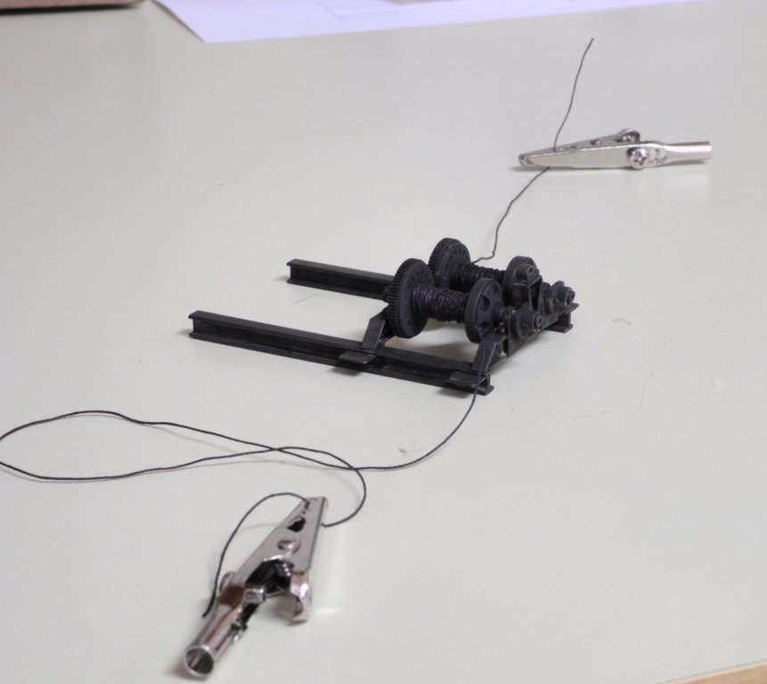
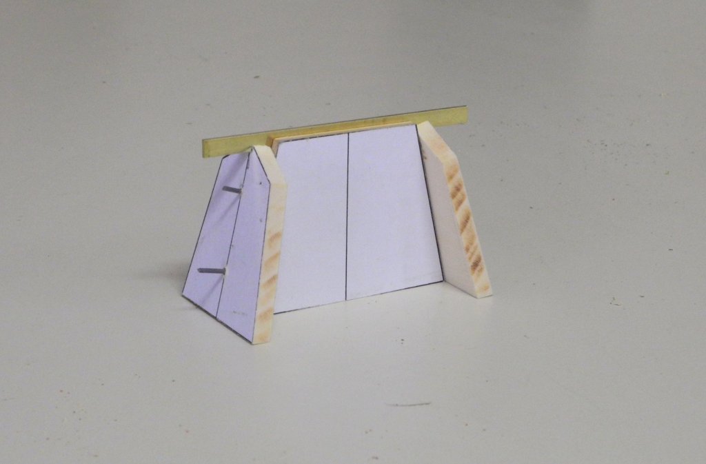
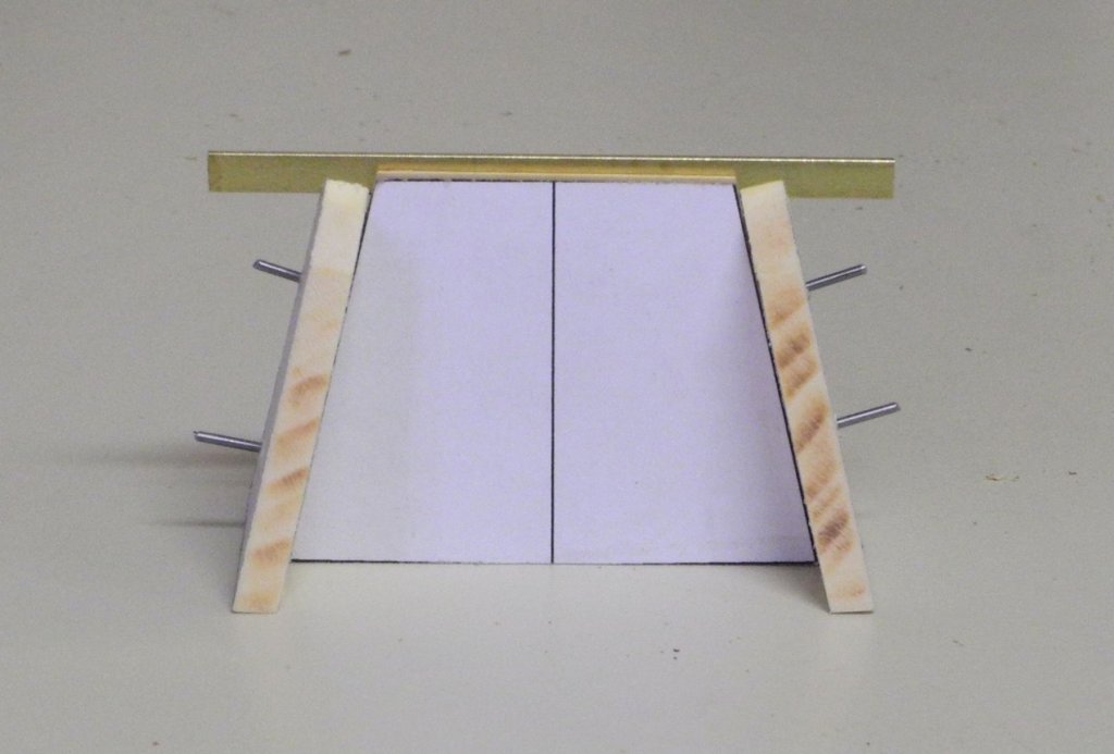
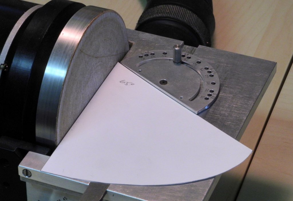
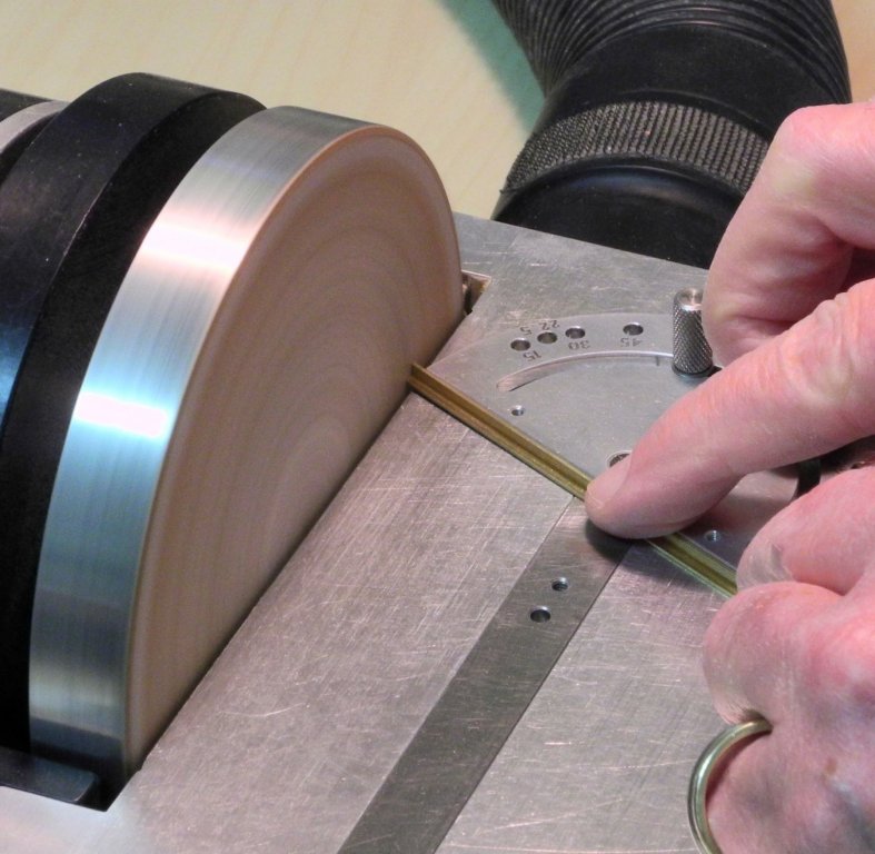
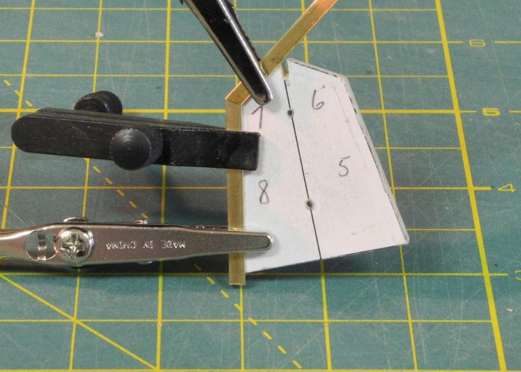
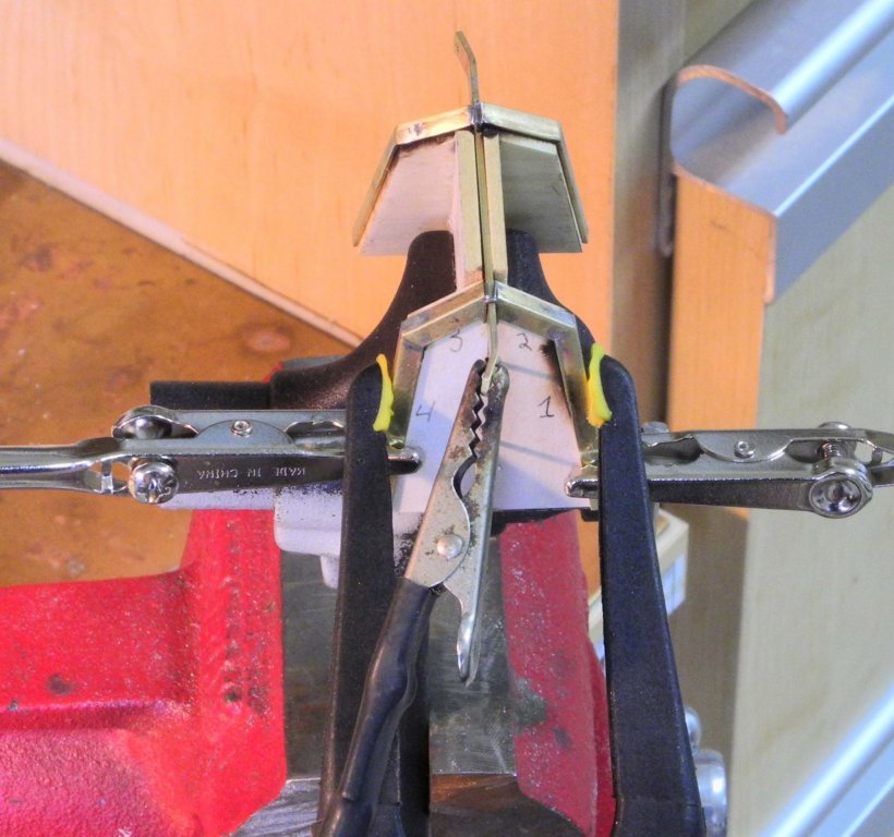
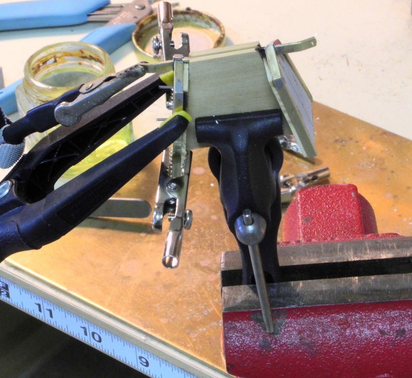
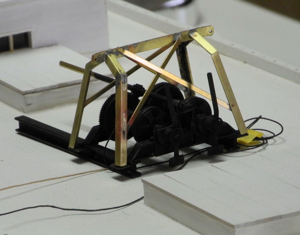
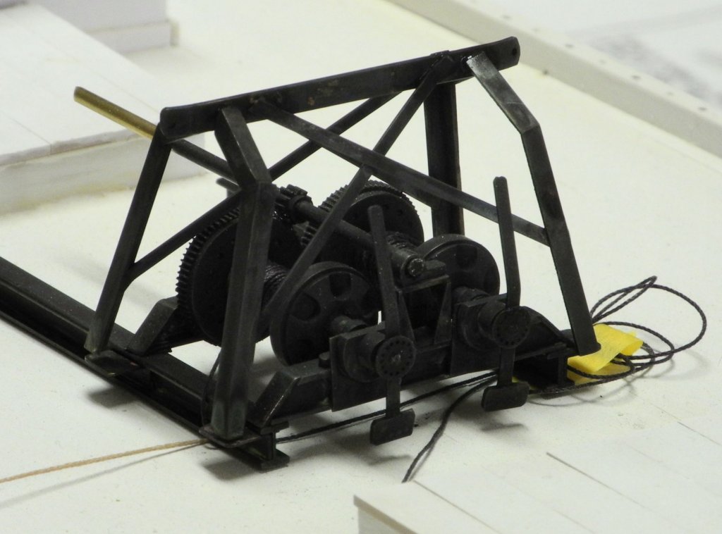
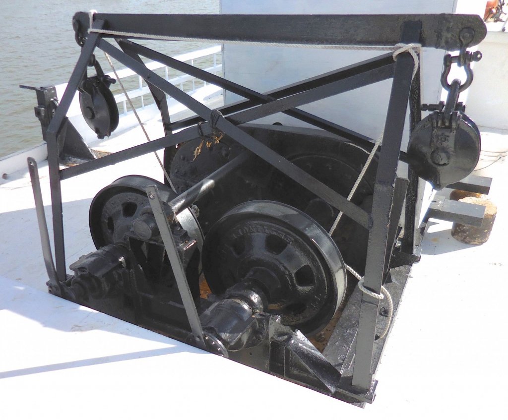
Part 51 – Kathryn’s Dredge Winder Cont’d It has been quite a while since my last post. Here in Arizona, February and March are very popular months for visitors, and we had our share this year. So time in the shop has been hard to get for the past 6 weeks or so. I did mange to get a little done, and the last few days have been fairly productive. The last photos showed the winder completed but still not blackened. The next photos show it after blackening (yes, I thought about leaving the brass natural, but I want to show Kathryn as she actually looks, so I needed to blacken the winder). The dredges are hauled on cables, but metal cables would be difficult to wind around the winder drums, so black rope was used on the model instead. After winding the rope around the drums, matte medium was painted on the rope to keep it from loosening. The frame around the dredge winder is constructed from angle iron. There is 1/16 and 1/8 brass angle iron available, but neither size was appropriate (I needed 3/32). So 1/32 was milled off each side of the 1/8 angle iron using the setup shown in the following photo. The silver-colored clamps are homemade clamps that provide additional reach over the standard Sherline clamps. The ends of the frame are constructed with angles rather than straight, and the ends are canted inward, as in the following construction drawing. A wooden form was made to support the construction of the winder frame. The angle on each side of the end pieces is 130 degrees, so the disk sander miter gauge was set at 65 degrees and the ends of the angle irons were sanded to this angle. The end pieces of the form were removable to allow for clamping of the pieces. Although the form is wood, it was able to withstand the resistance soldering which localizes the heat. This setup probably wouldn’t work very well for soldering with a torch. Once the individual sides of the ends were soldered, the complete form was used to join all of the pieces to the crossbar. In the above photo, a small hand vise is holding the form, and this small vise is being held in the bench vise. The basic frame was completed, but still needed the cross-braces. The soldering of the cross-braces required some extra effort to keep from opening the joints already soldered. Pieces of paper towel that had been soaked in water were clamped around existing joints to prevent the heat from opening those joints. The following photos show the winder frame completed and blackened and temporarily in place. Additional work on the blackening is still needed. Here’s a photo of Kathryn’s real winder and frame. The pulleys hanging from the crossbar still need to be made, as well as the boards that are beneath the I-beams. The housing for the engine that drives the winder also needs to be made. The winder configuration will then be put aside until later in the project so it doesn’t interfere with other delicate construction work. Thanks everyone. I hope to post more frequently now that work is again under way.


- 878 replies
-
- 30
-
-
Hi Elia I'm looking forward to seeing more progress on Arethusa. I've ordered Chuck's internally stropped blocks after seeing yours during your visit, and really like them. I wish there were some smaller versions for my Kathryn build, since they're slightly bigger than I need for some of the rigging. The traditional blocks that are available aren't configured like the more modern blocks used on Kathryn, so I'll need to decide whether I try to make my own. I know it can be frustrating to not be able to make progress on your model - many other modelers run into the same issues with life and responsibilities getting in the way. EdT's Victory model is a great example of completing a build over many years - started in 1976 and finished in 2009 and very much worth the wait. I've seen it in person and it's superb - hard to believe it was his first model.
-
Outstanding work, Ed. The photos and explanations help me to understand a subject I've previously thought to be too complex for me to comprehend.
- 3,618 replies
-
- 4
-
-
- young america
- clipper
- (and 1 more)
-
Great work as usual, Ed. Your approach to centering the rotary table solves a problem I've had to deal with, so I'll definitely be using it.
- 3,618 replies
-
- 3
-
-
- young america
- clipper
- (and 1 more)
-
Hi Patrick Very nice photos - I especially like using the light to highlite all the windows.
-
Thanks Roger. I would add a willingness to throw a bad part away and keep trying until you get it right.
-
Hi Patrick Thanks for the kind comments. You're right - some non-modelers may not get it, but that's OK. I enjoy the modeling, and that's the most important thing.
-
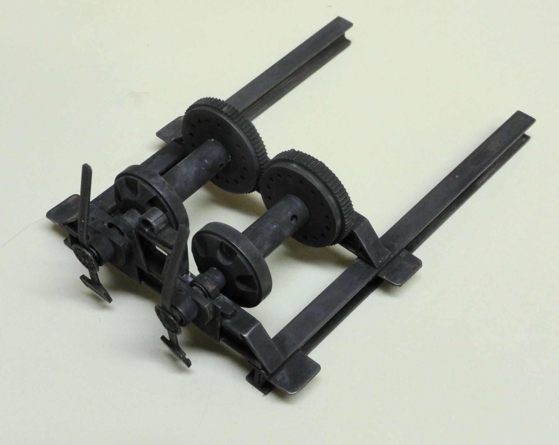
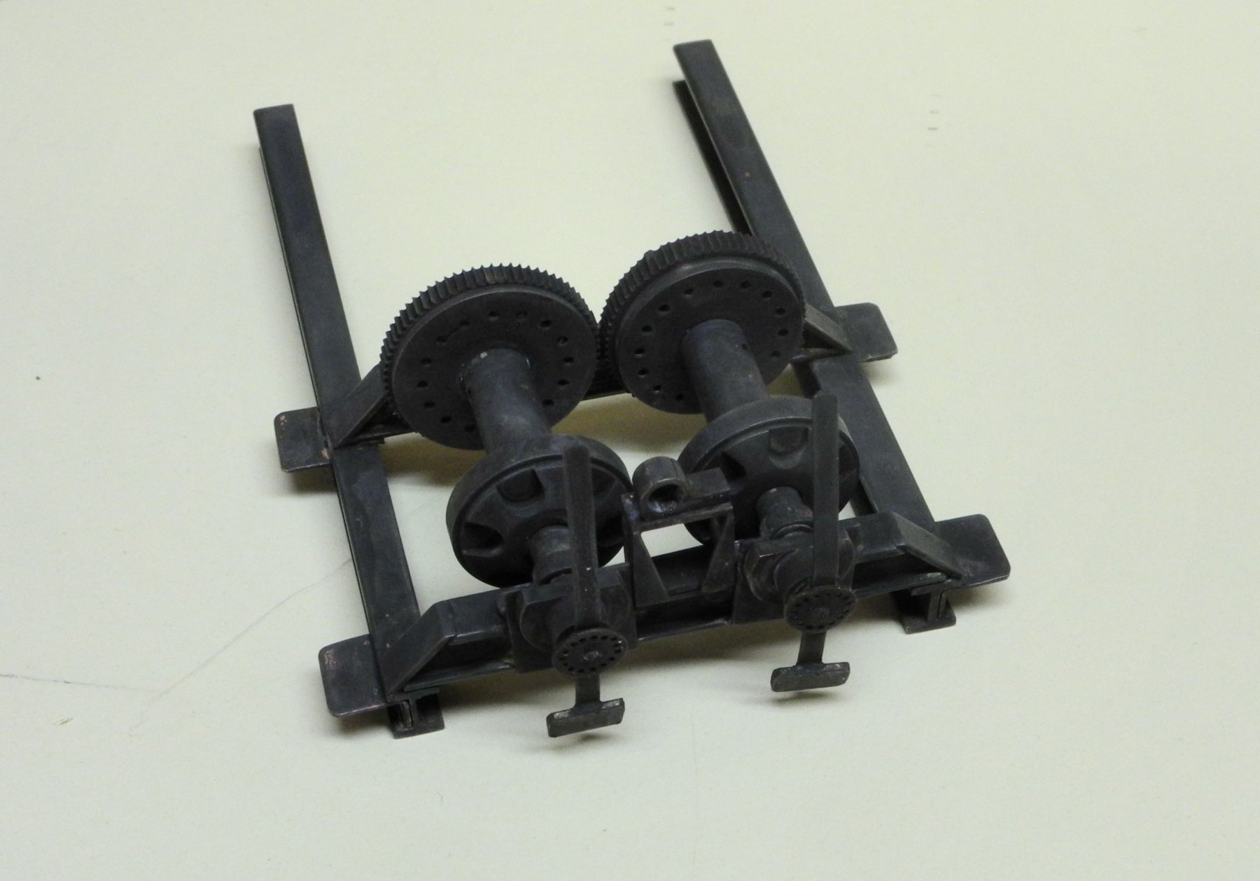
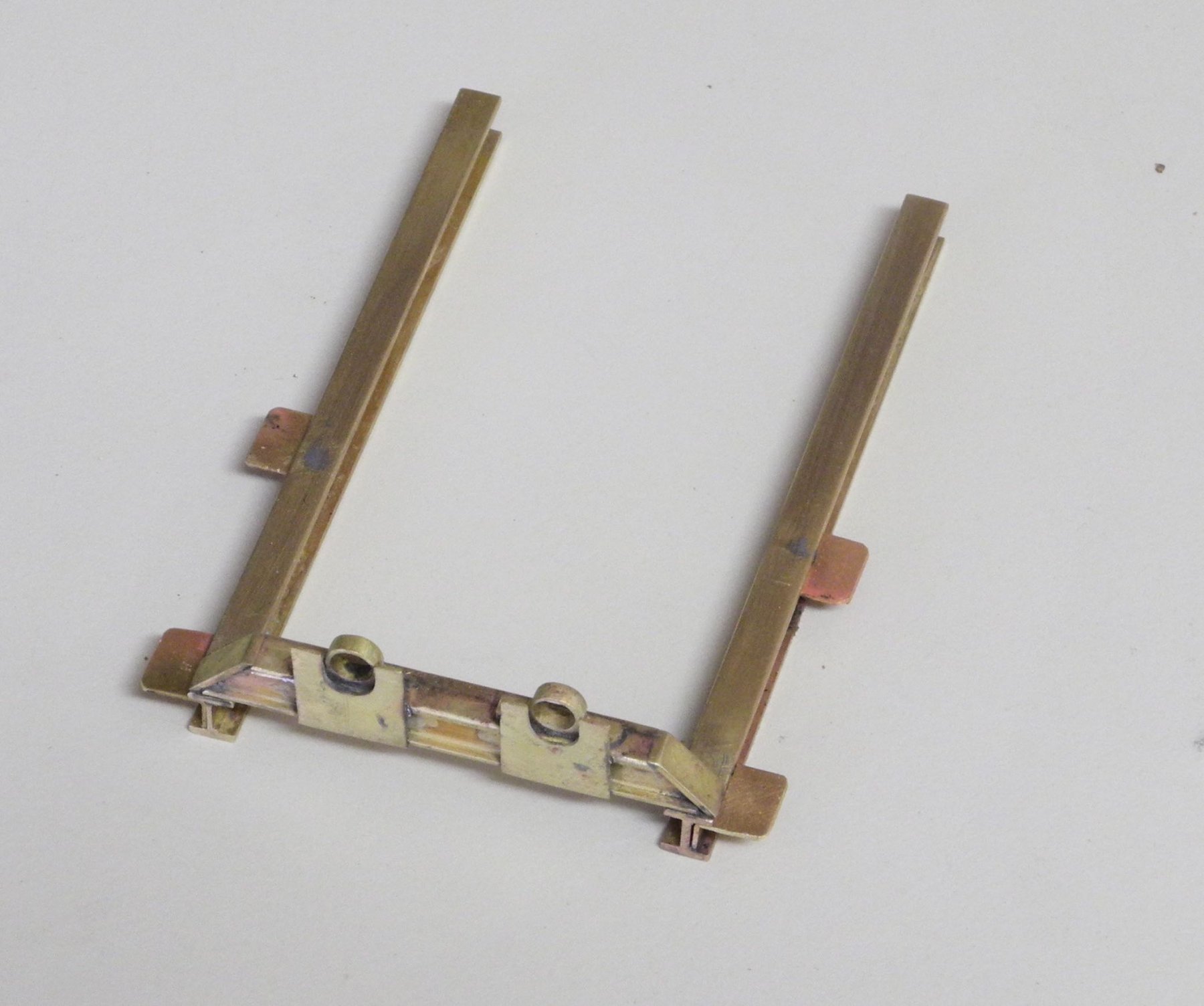
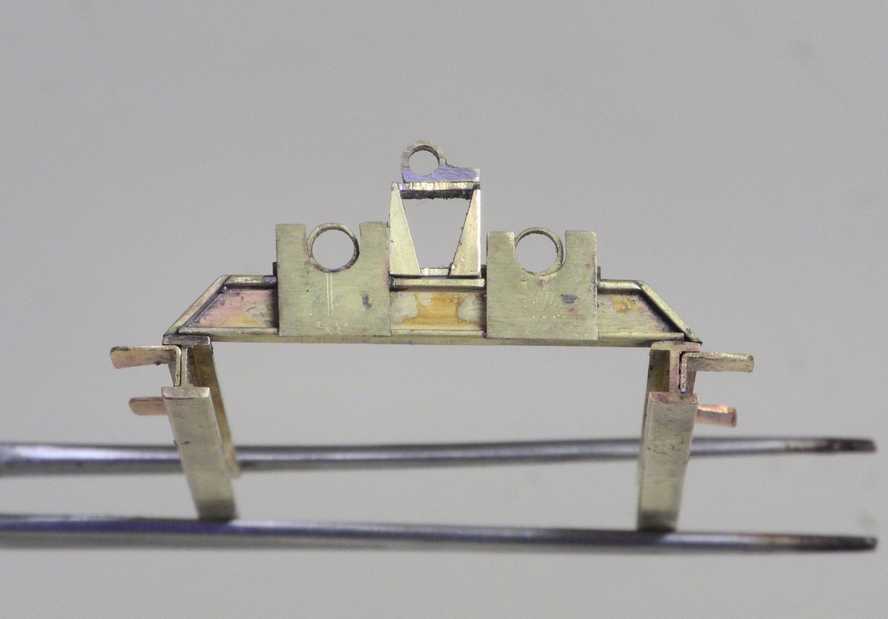
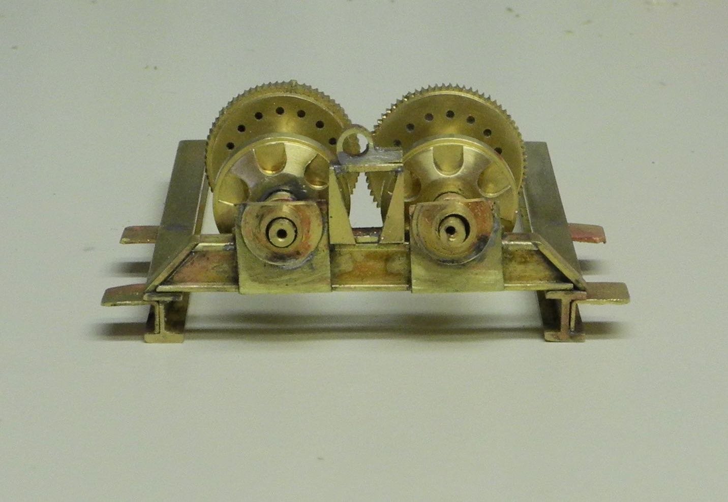
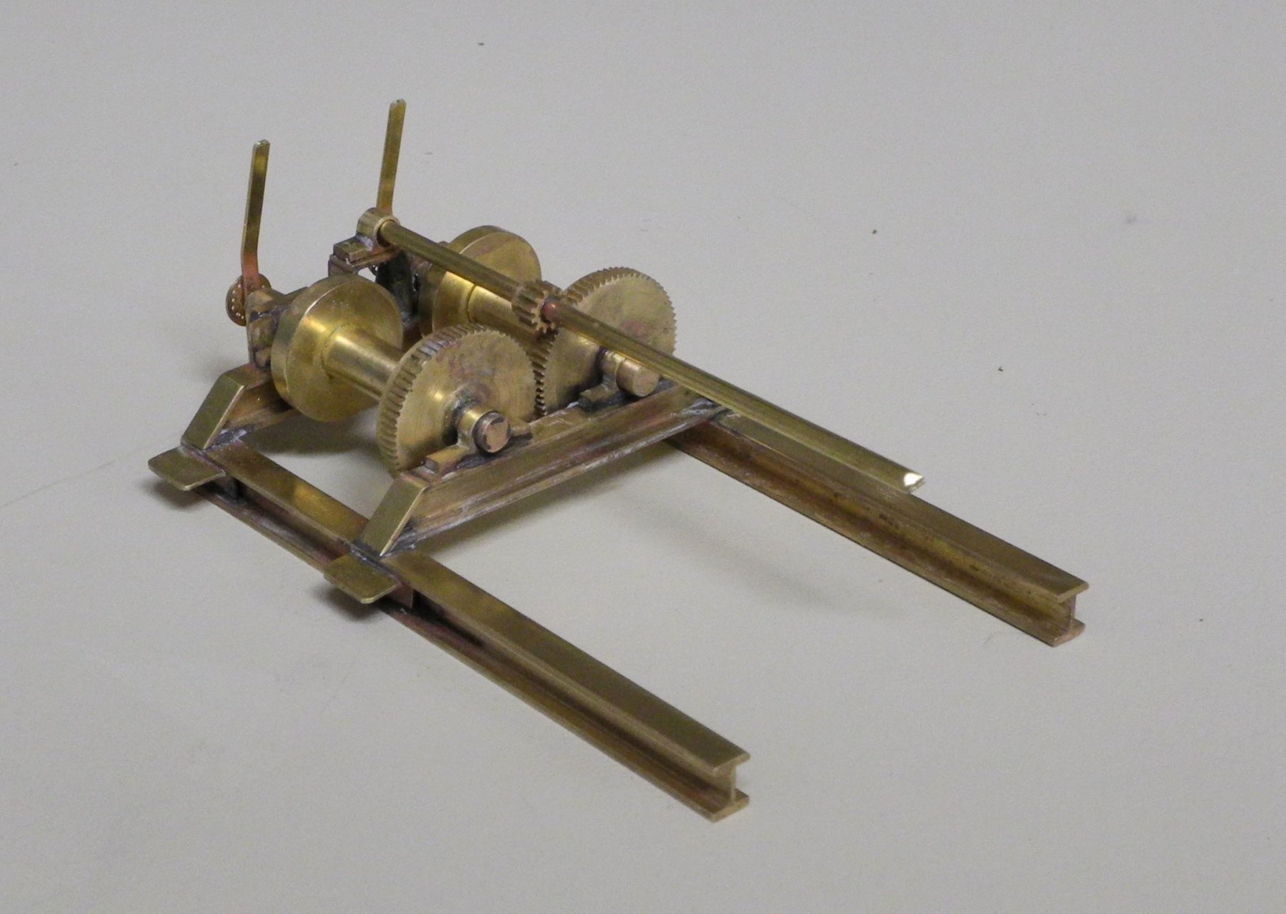
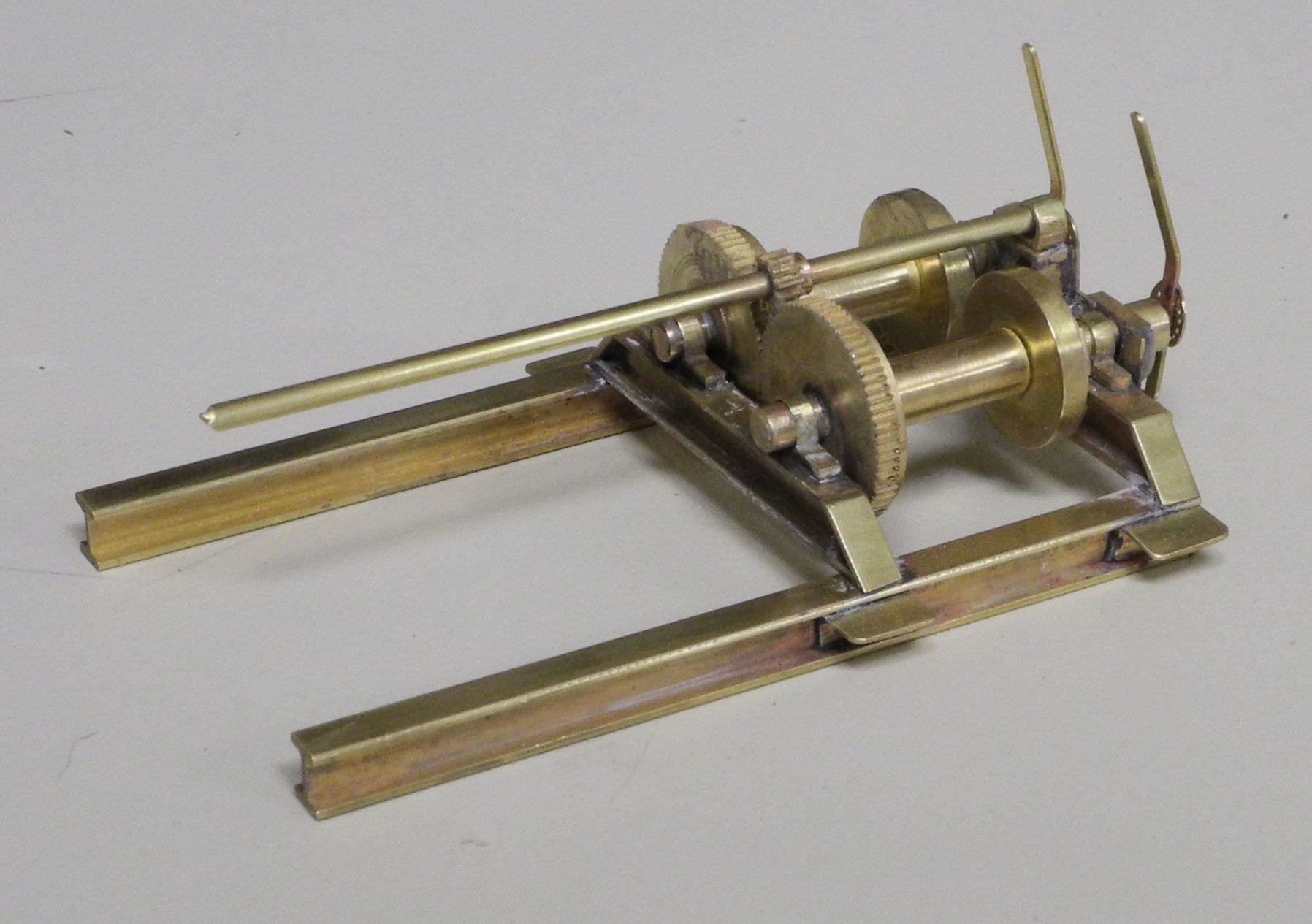
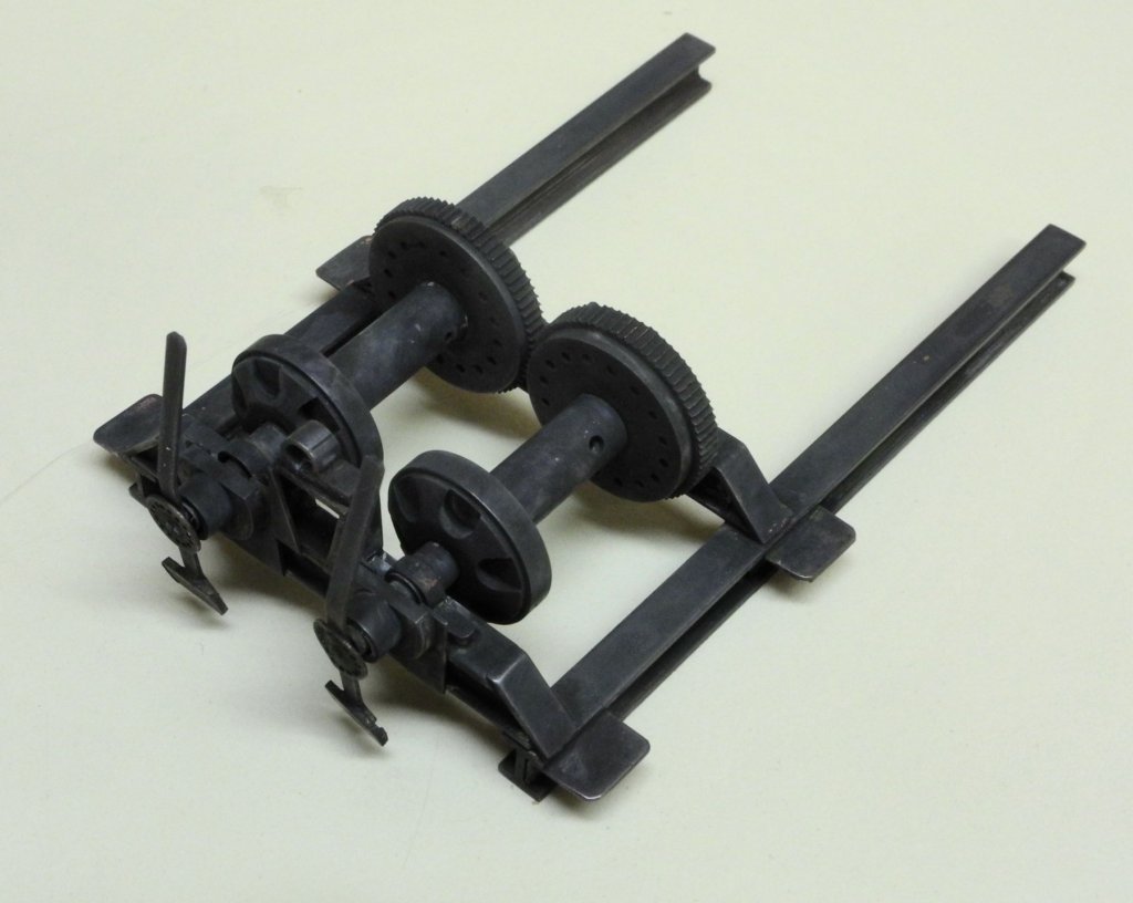
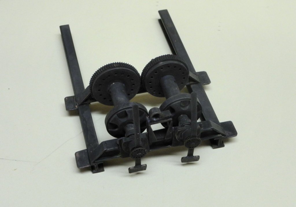
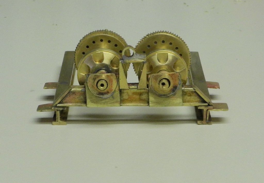
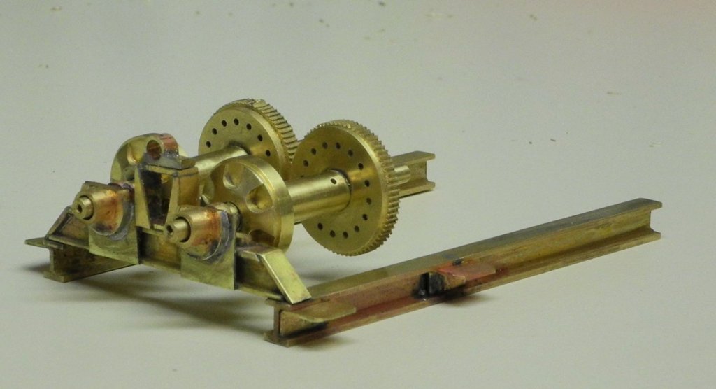
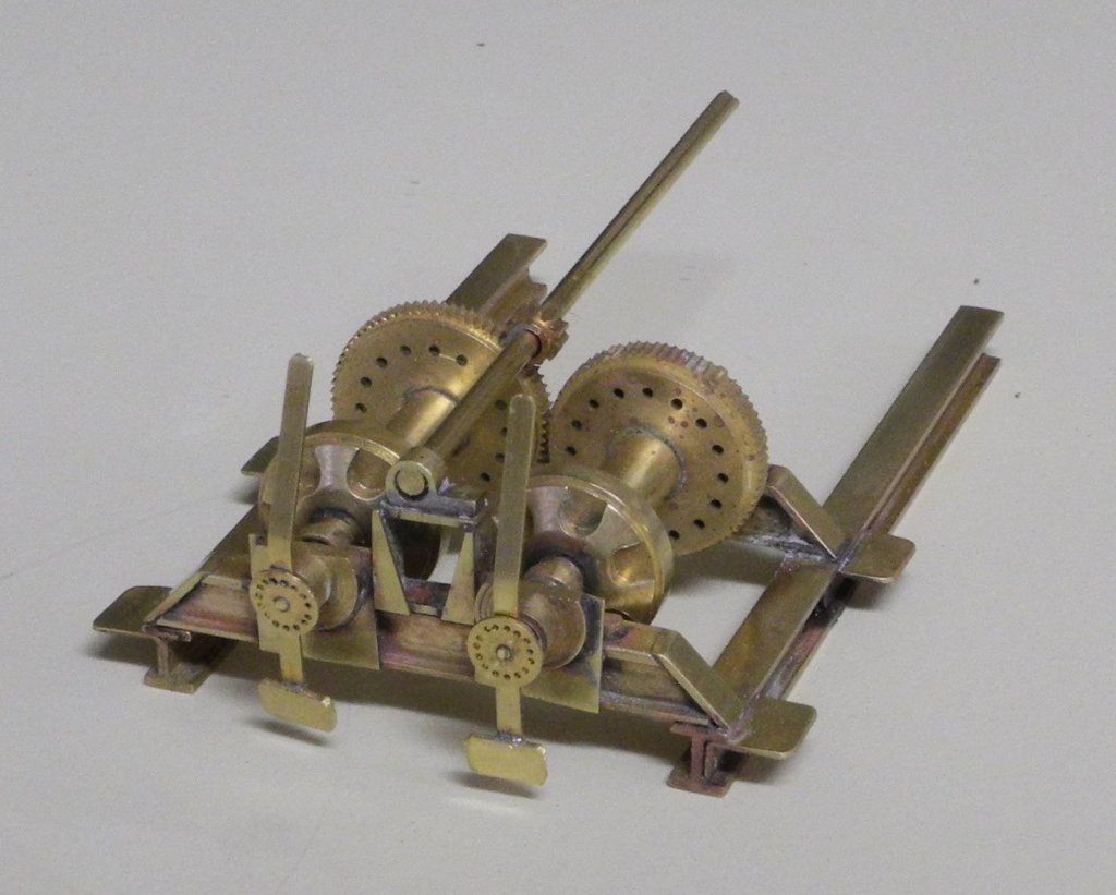
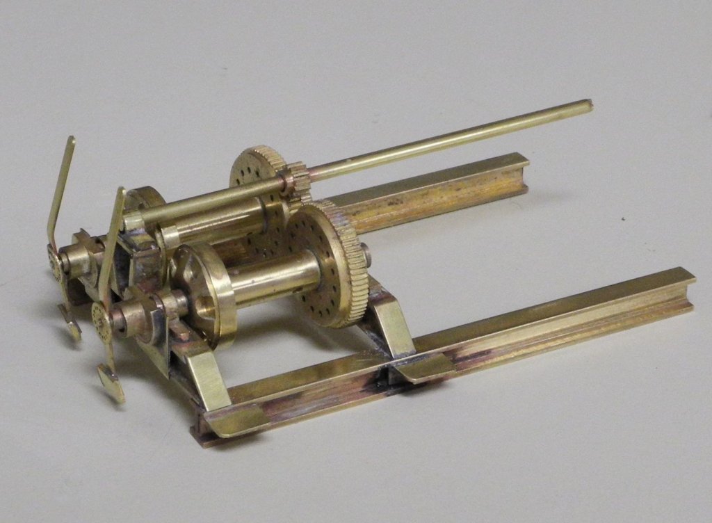
Part 50 – Kathryn’s Dredge Winder Cont’d After fabricating the parts for the winder it became time to assemble them into the finished product. The winder will have an A-Frame over it, and the legs of this A-Frame will rest on small tabs protruding from the I-Beam base. These tabs were made by bending small pieces of sheet brass into the proper shape. The following photos show the tabs installed, along with the mounting brackets for the front axles of the winder drums. The clutch assemblies are mounted to plates welded to the front crosspiece of the winder frame. These plates were soldered as the next step. The clutch assemblies were then soldered to the plates. In addition, the support for the drive shaft, including the mounting bracket for the shaft, was also soldered onto the front crosspiece. The drums were hung off the front brackets to help align the clutch configurations. The rear crosspiece was soldered in place with the drums still hanging off the front brackets, since the drums would not be able to be fit between the cross pieces if they were left until later in the assembly process. The rear drum brackets were soldered to the rear crosspiece, and the drive gear and shaft were temporarily mounted in place. The drums still turn, so that will make it easier to wind the dredge cable around them. The clutch handles are temporarily in place, and will be epoxied into the drum shafts after everything is blackened. There was a lot of soldering in close quarters required, and resistance soldering was a big help in keeping solder joints from separating in later steps. There were still a few instances of solder failures and re-soldering. More cleanup of the brass will be the next step, followed by blackening the entire winder assembly. Thanks everyone for the likes and comments.


- 878 replies
-
- 22
-
-
Amazon has a selection of brass thumbscrews. https://www.amazon.com/Brass-Thumb-Screw-Knurled-Threads/dp/B00DD4X1BA
-
Another good material to use as a base for soldering is Corian. Besides being heat-resistant it can easily be milled so that it also acts as a jig for hard-to-hold pieces. I get scrap pieces from kitchen counter installers.