Mahuna
-
Posts
1,504 -
Joined
-
Last visited
Content Type
Profiles
Forums
Gallery
Events
Everything posted by Mahuna
-
 Thanks Ed. I often find myself asking "now, how would Ed do this?" You've set the bar for anything I try to accomplish.
 -
Thanks Patrick and Ken. I'm relatively new to machining, but it has become something I really enjoy. Of course, I haven't shown all of the failed attempts reach this point!
-
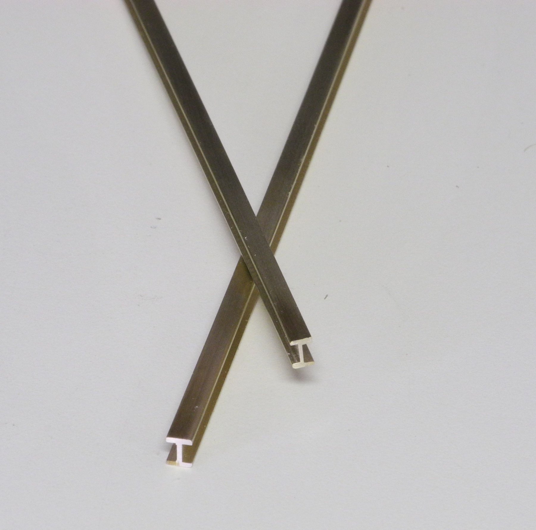
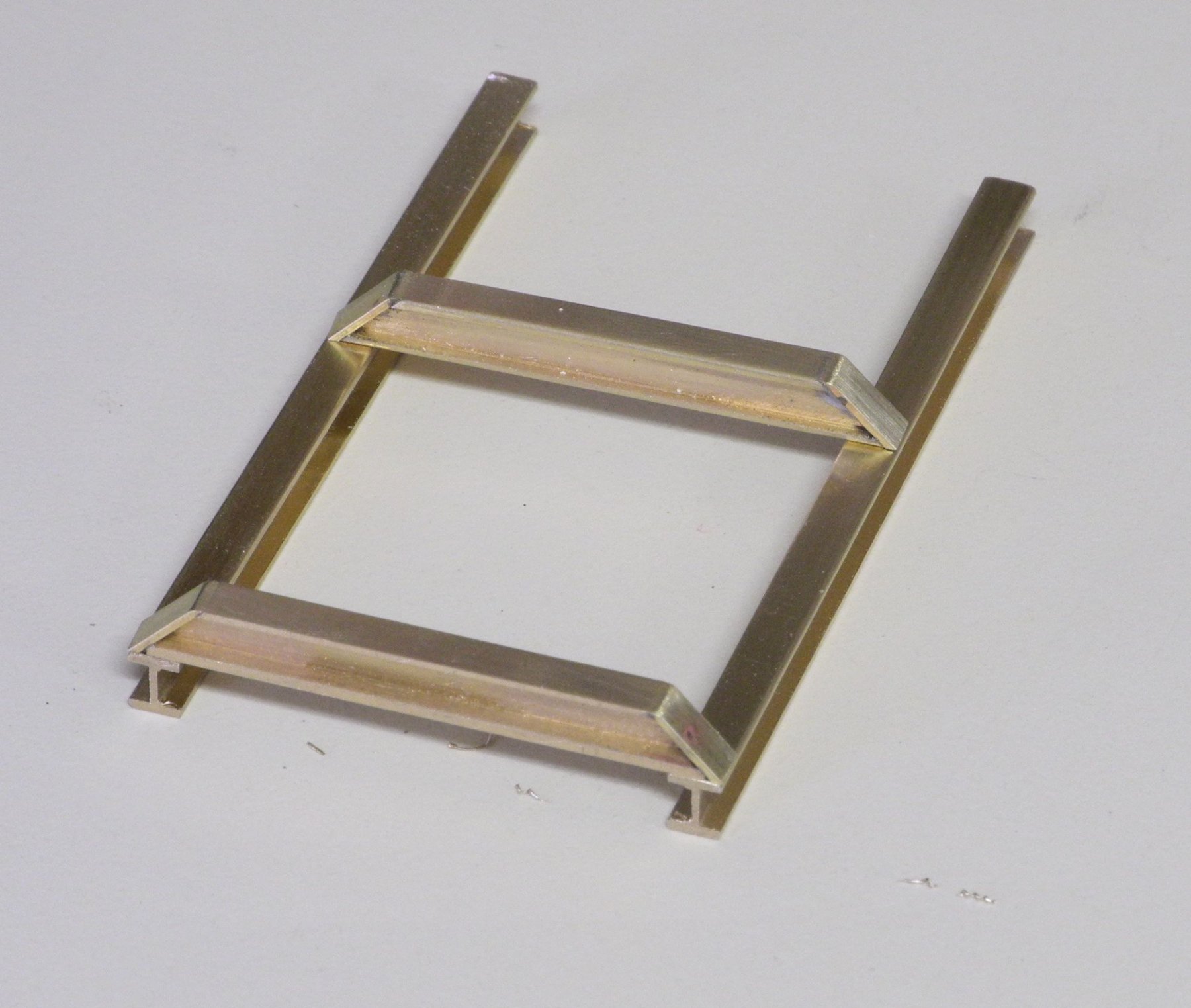
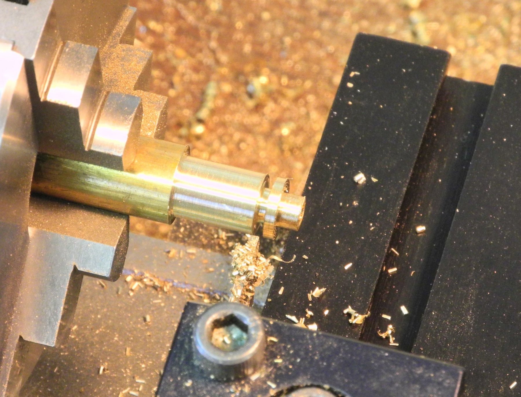
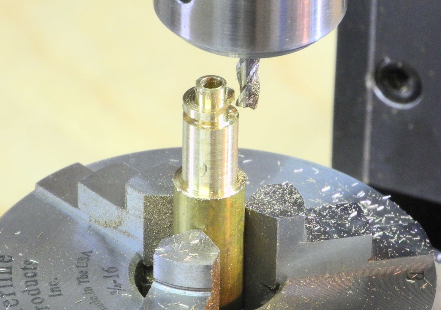
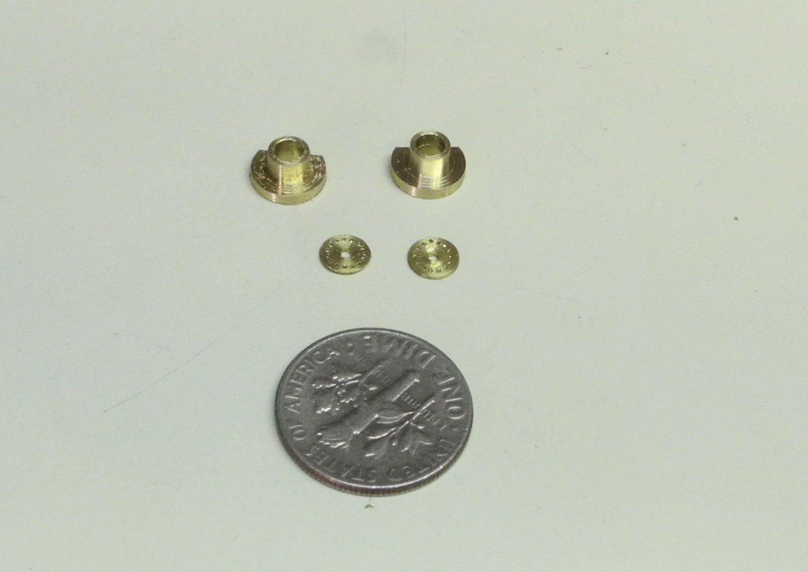
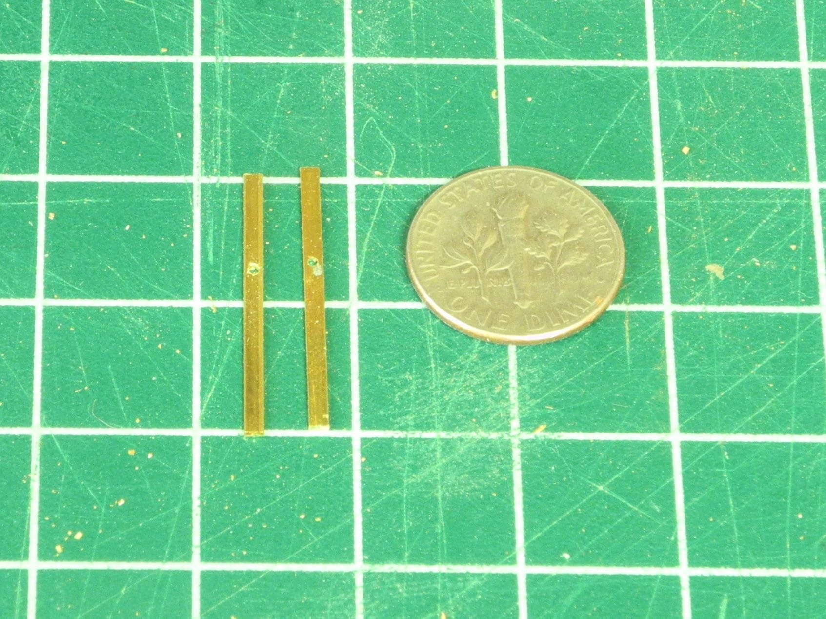
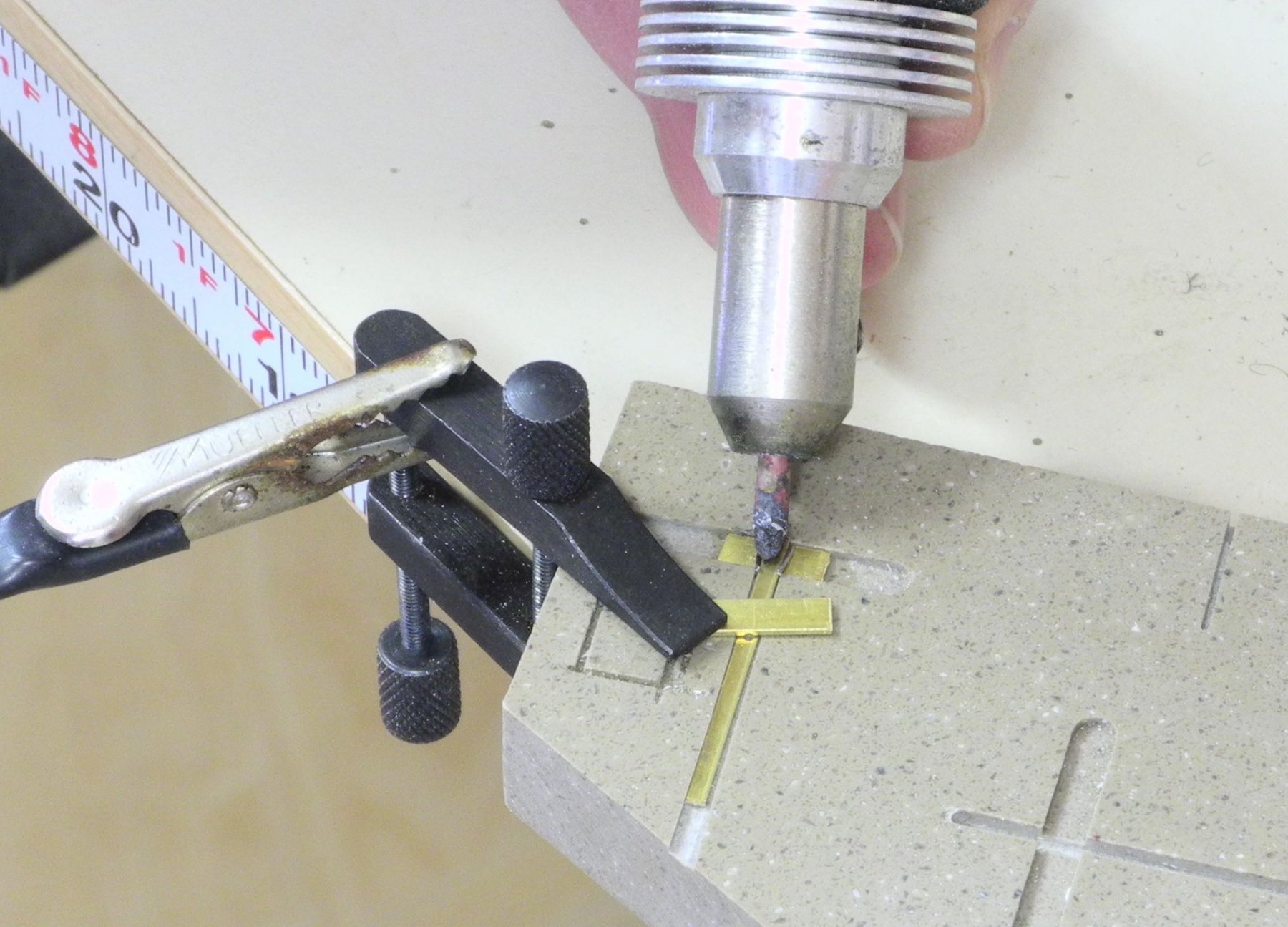
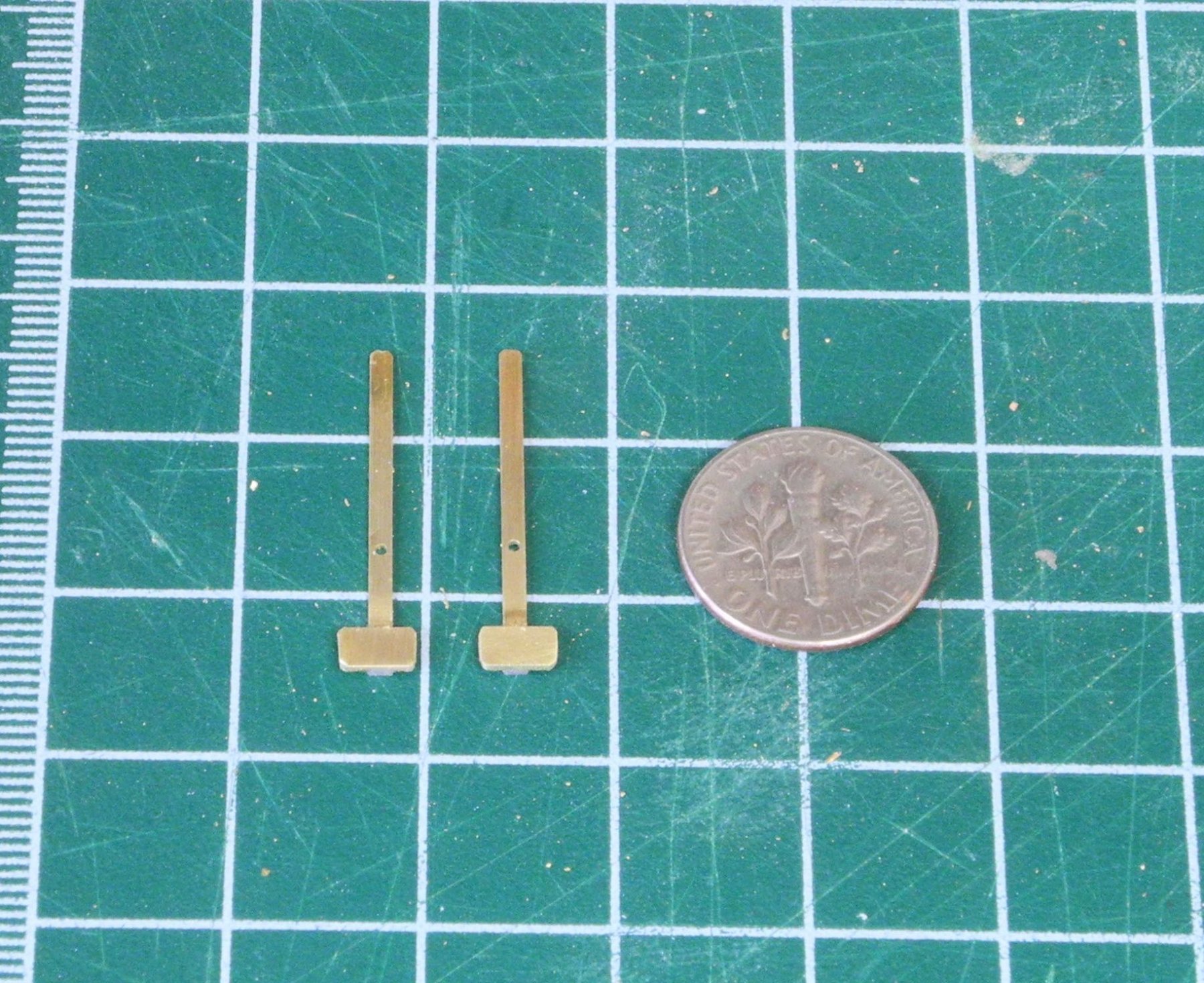
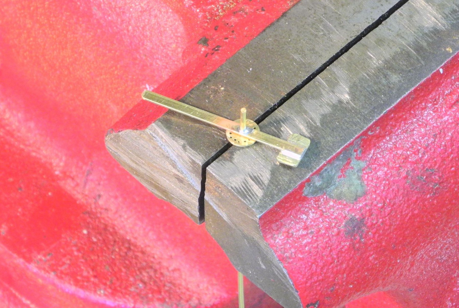
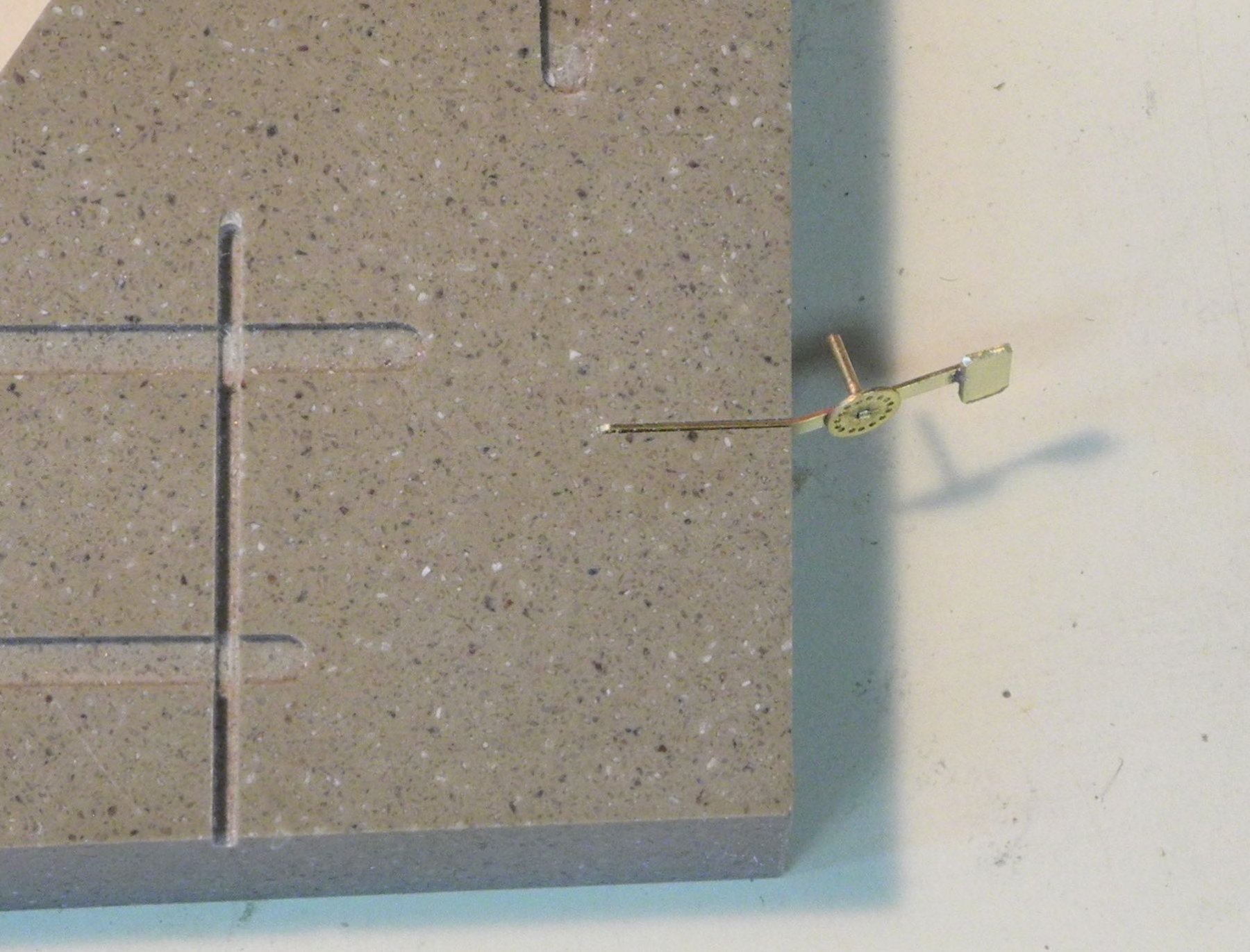
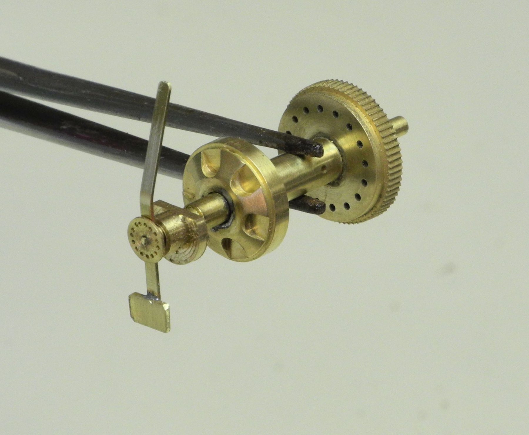
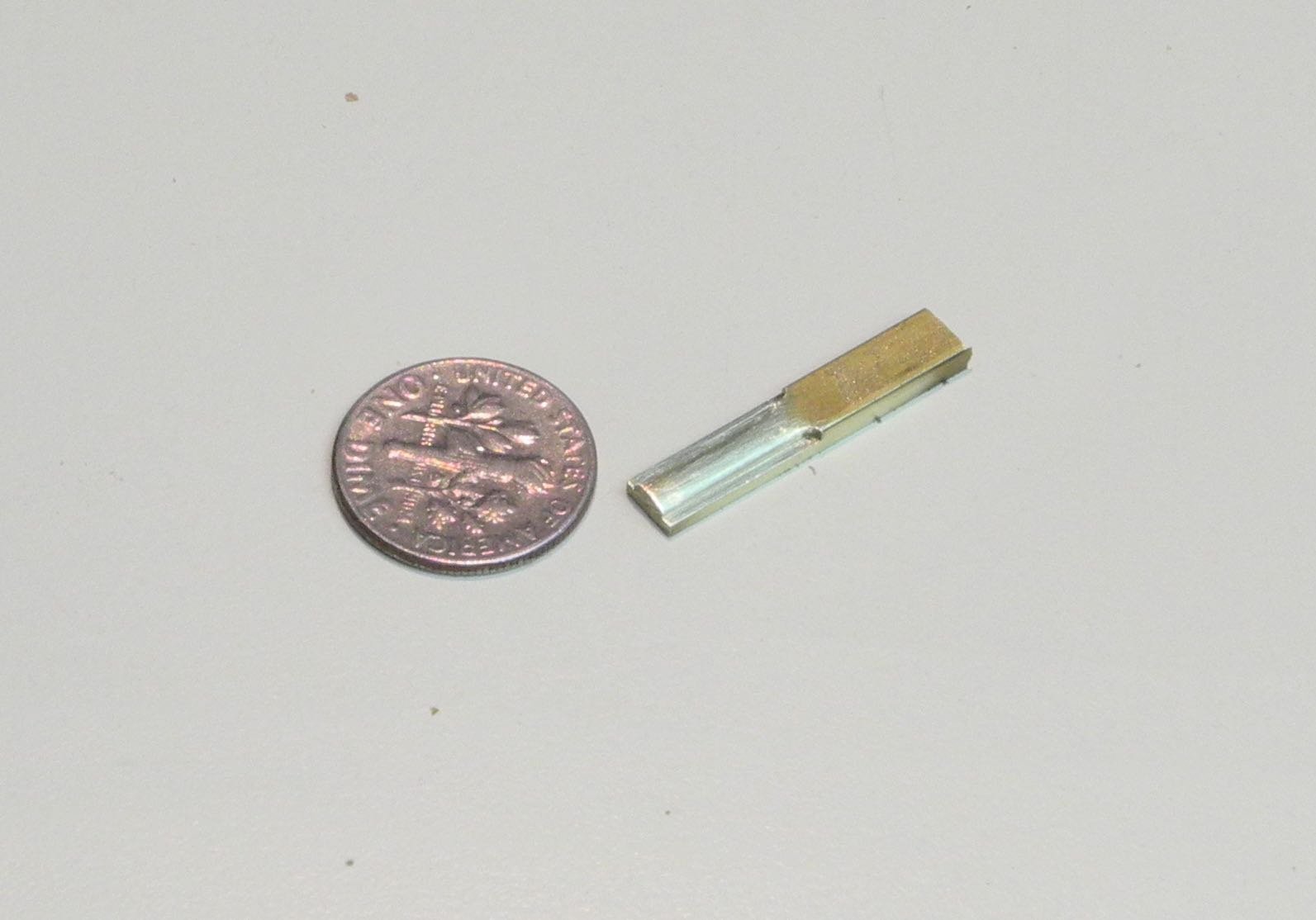
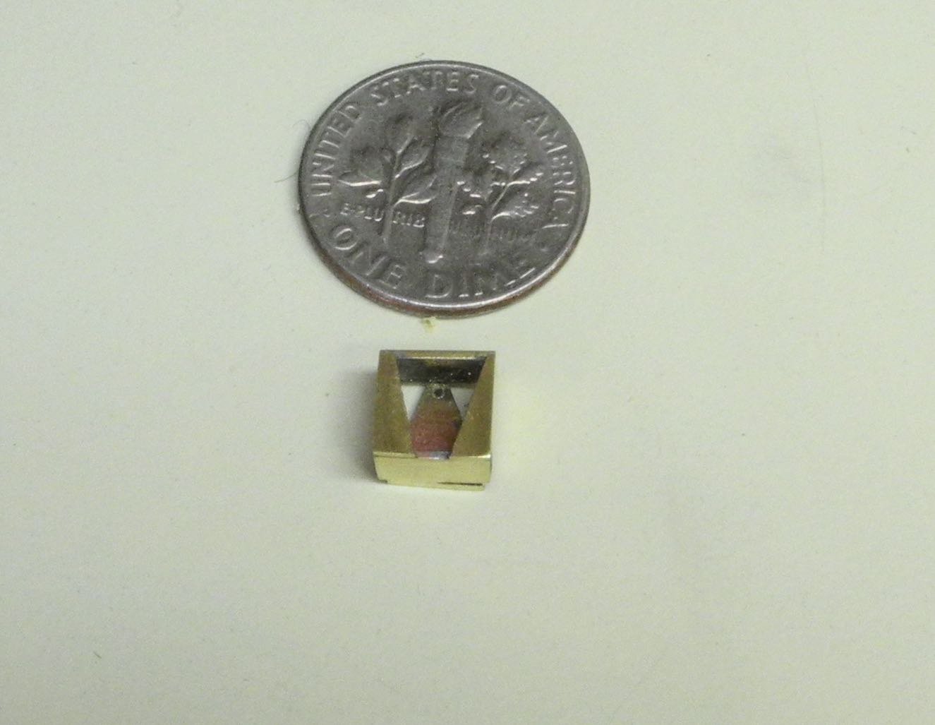
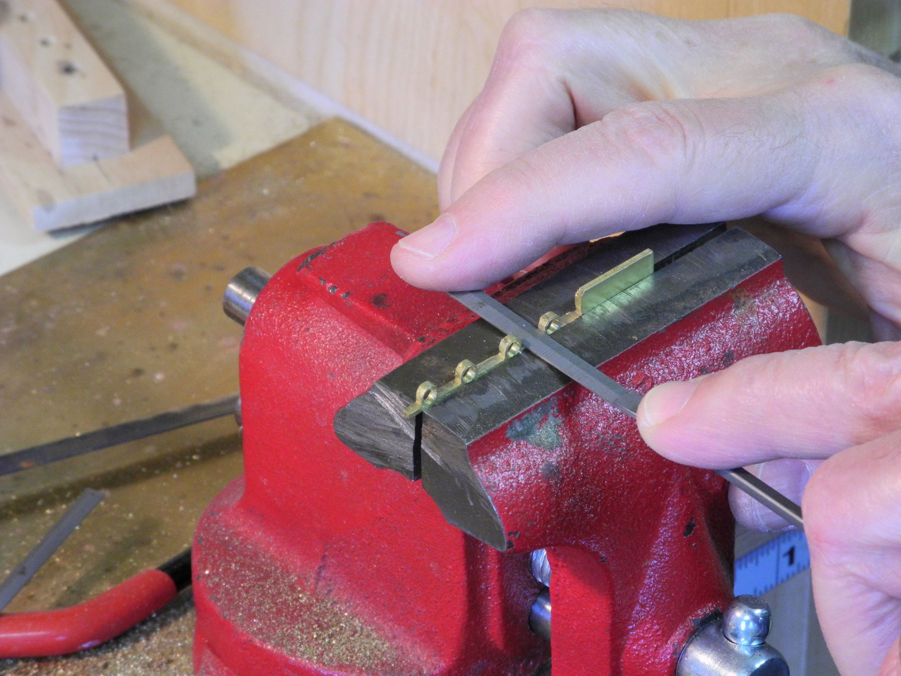
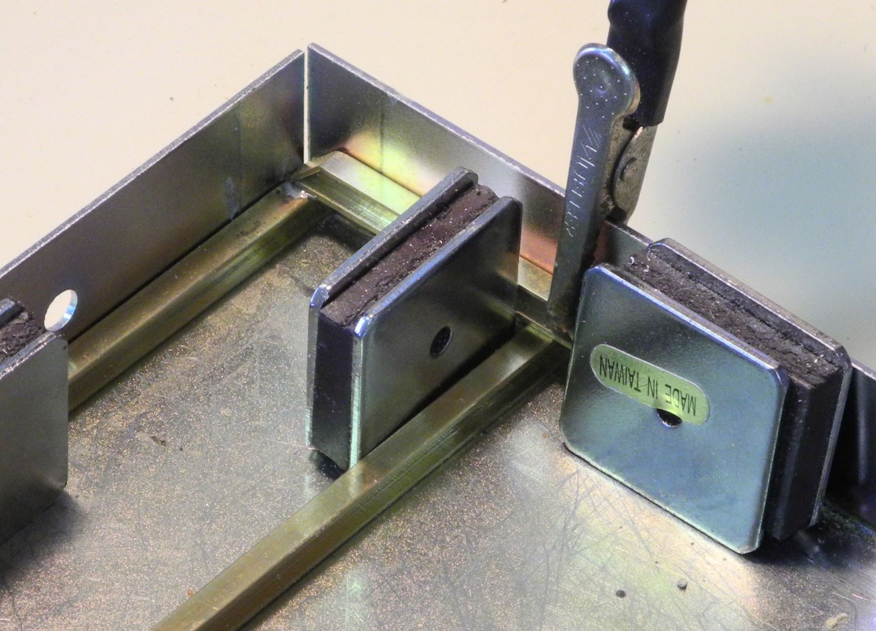
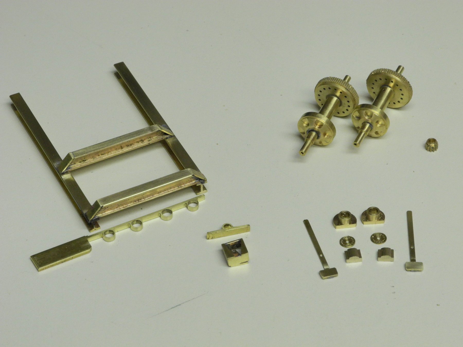
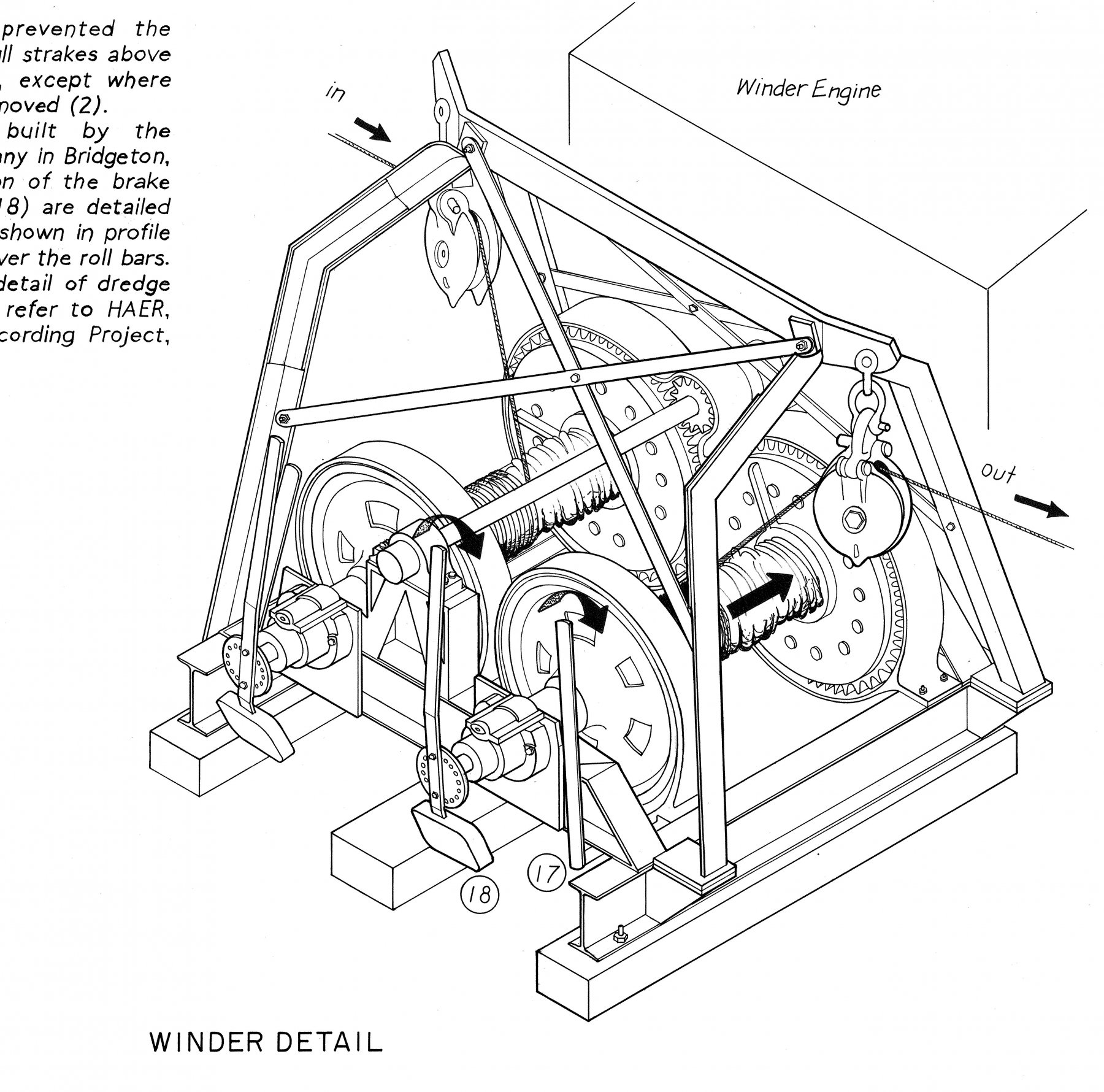
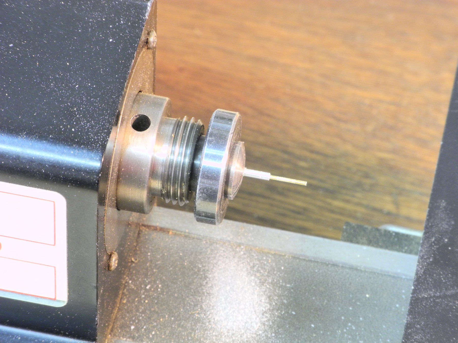
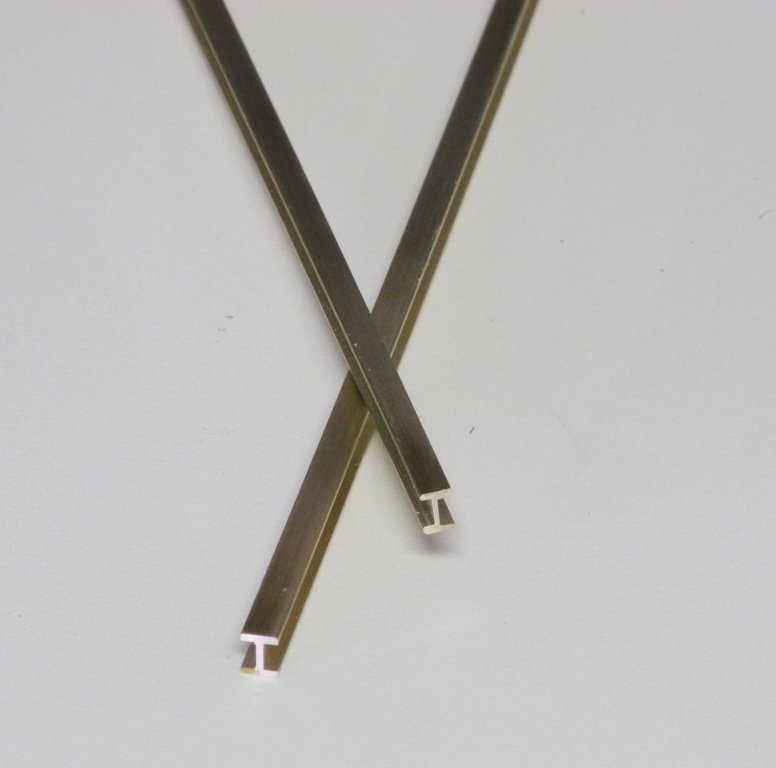
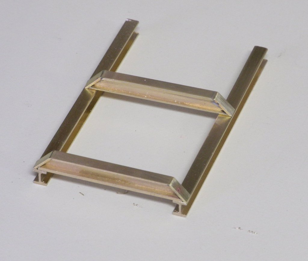
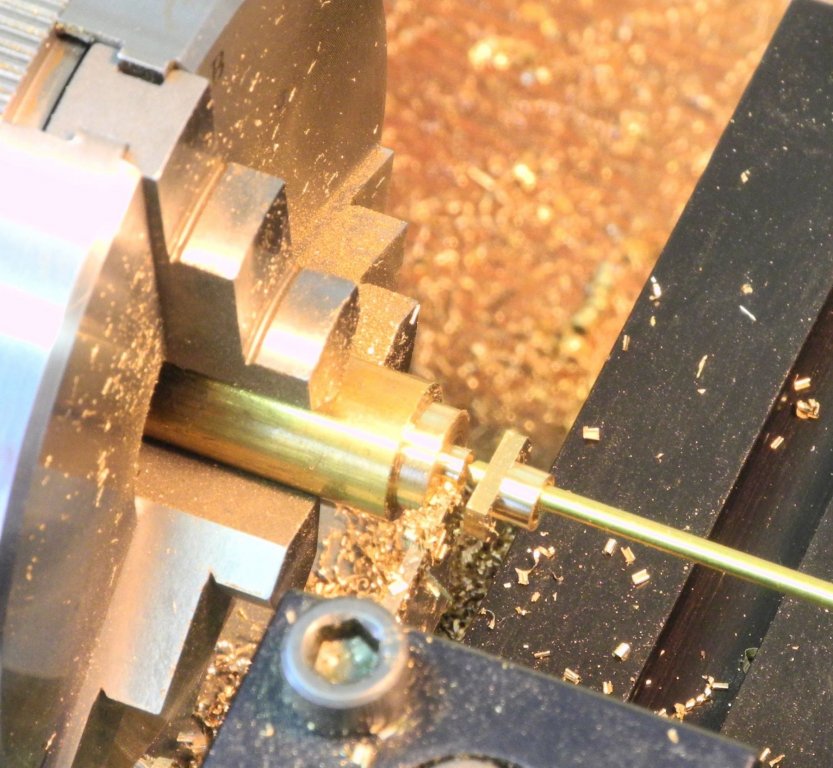
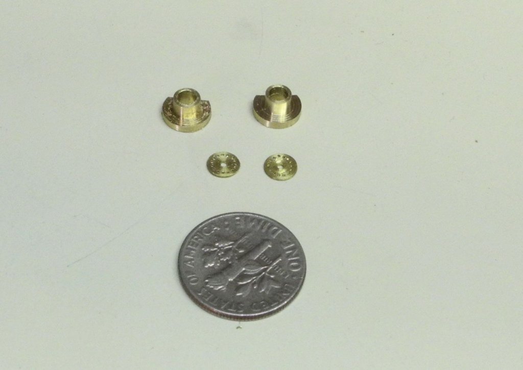
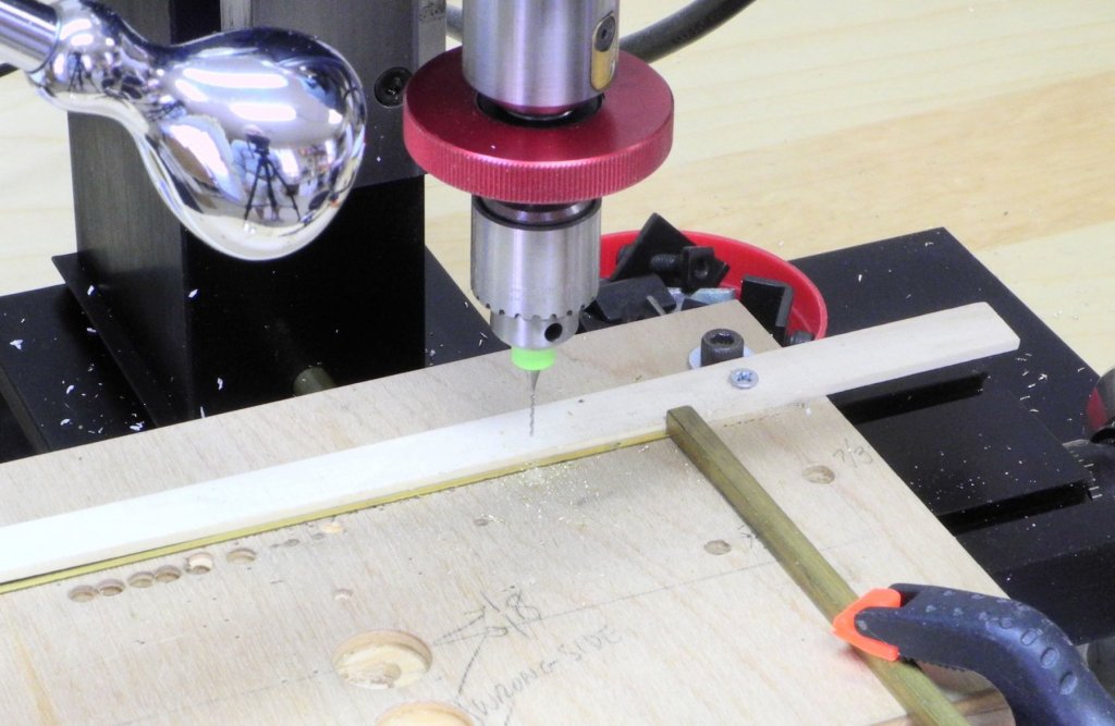
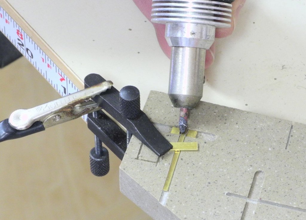
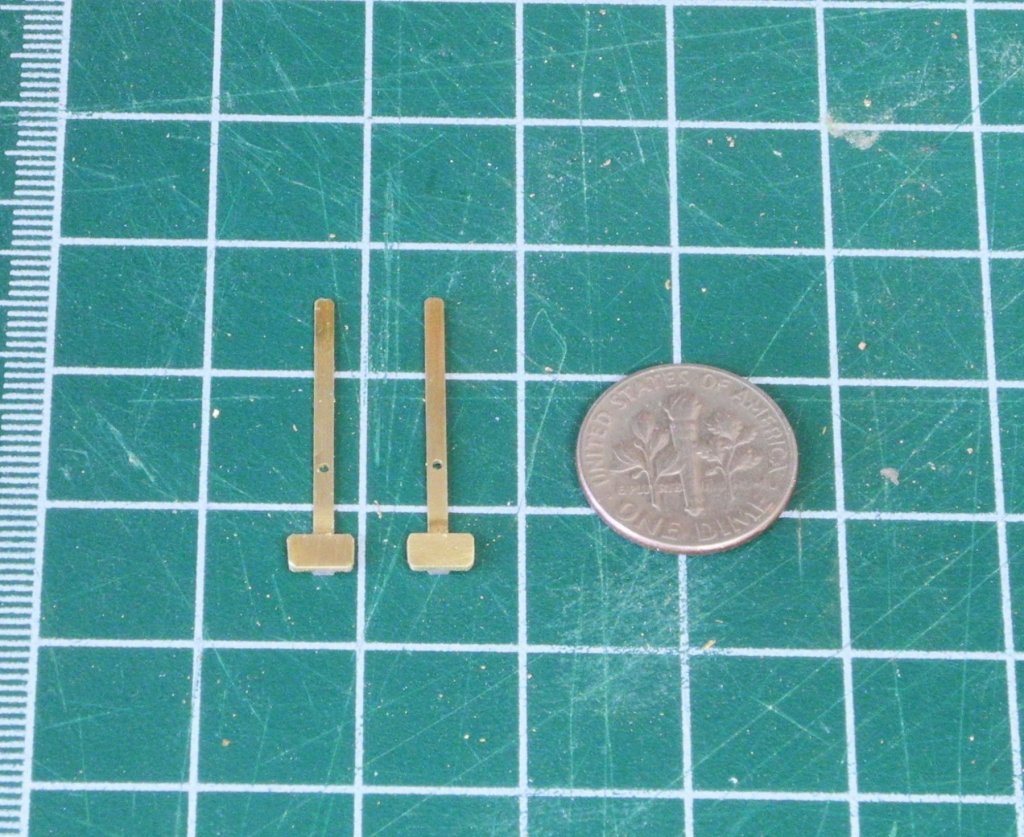
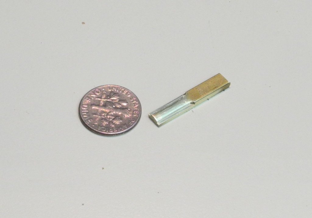
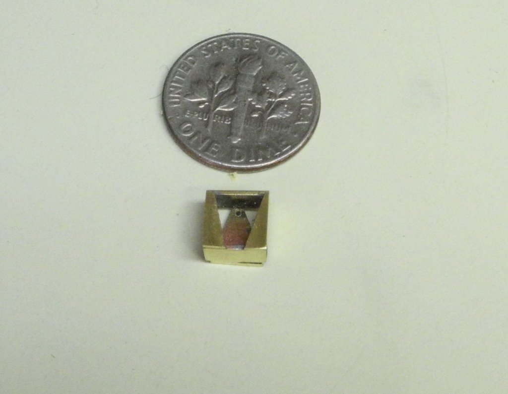
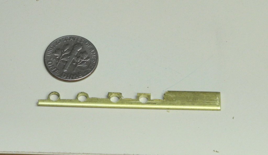
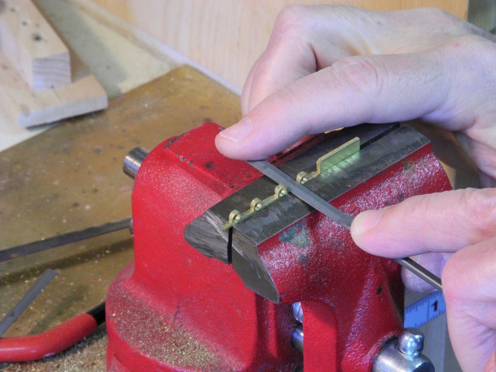
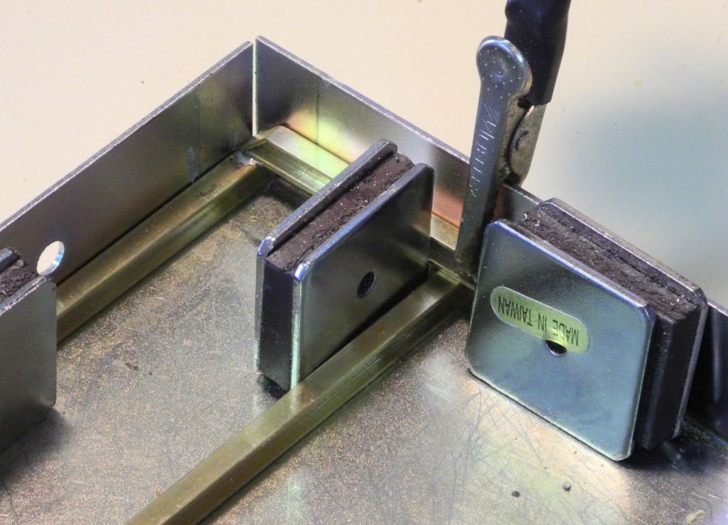
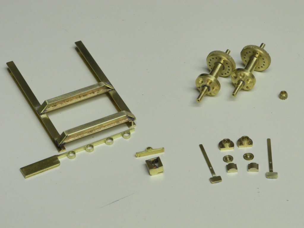
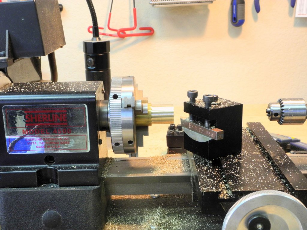
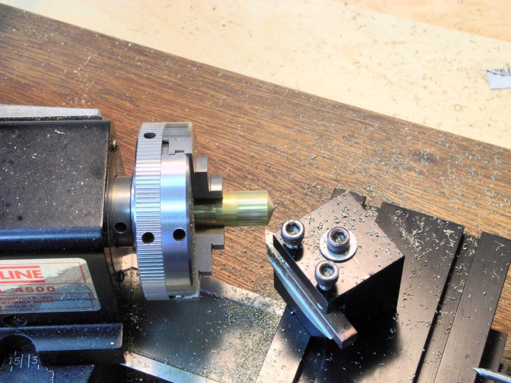
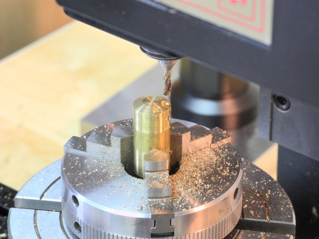
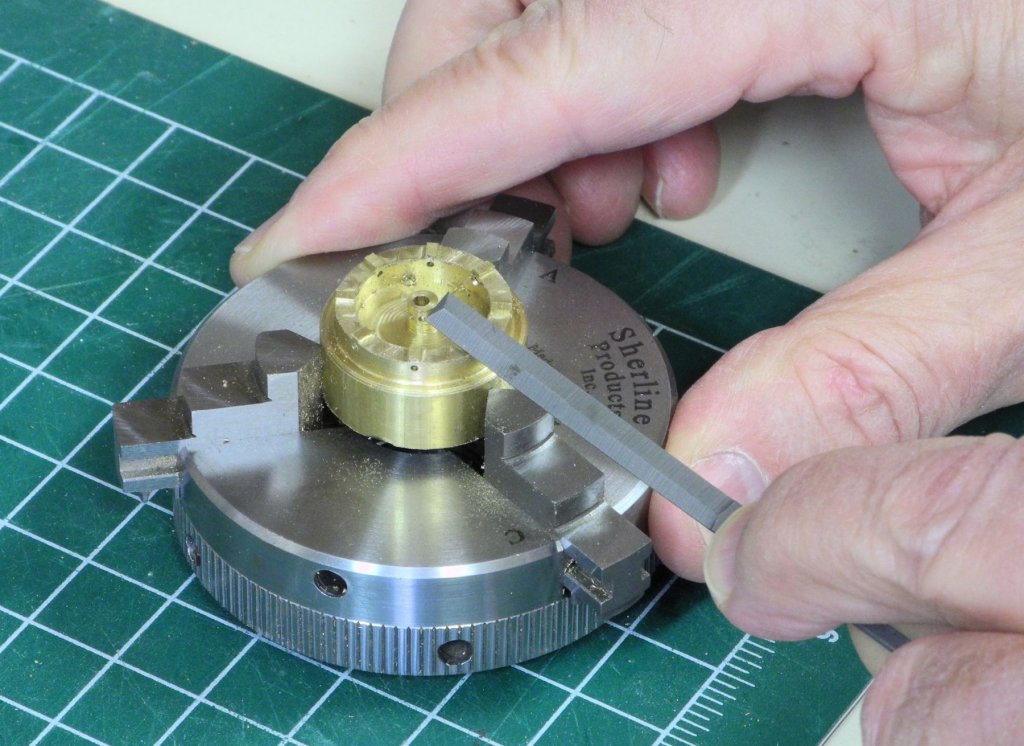
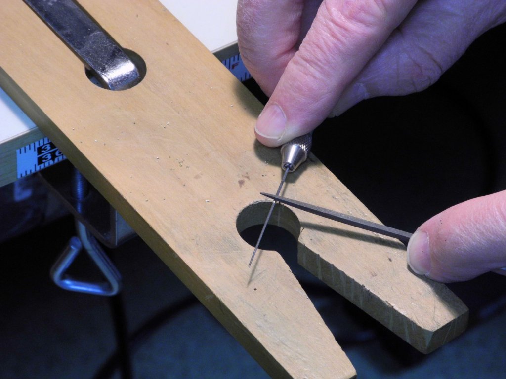
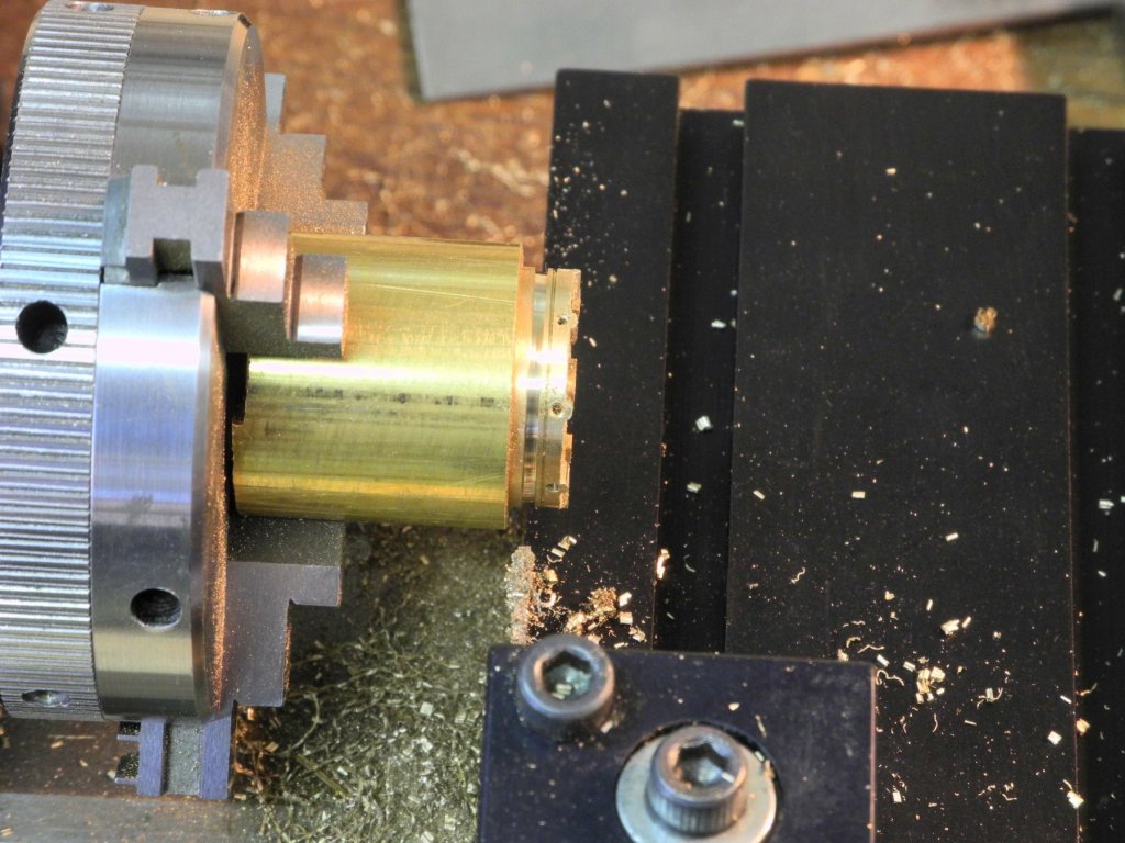
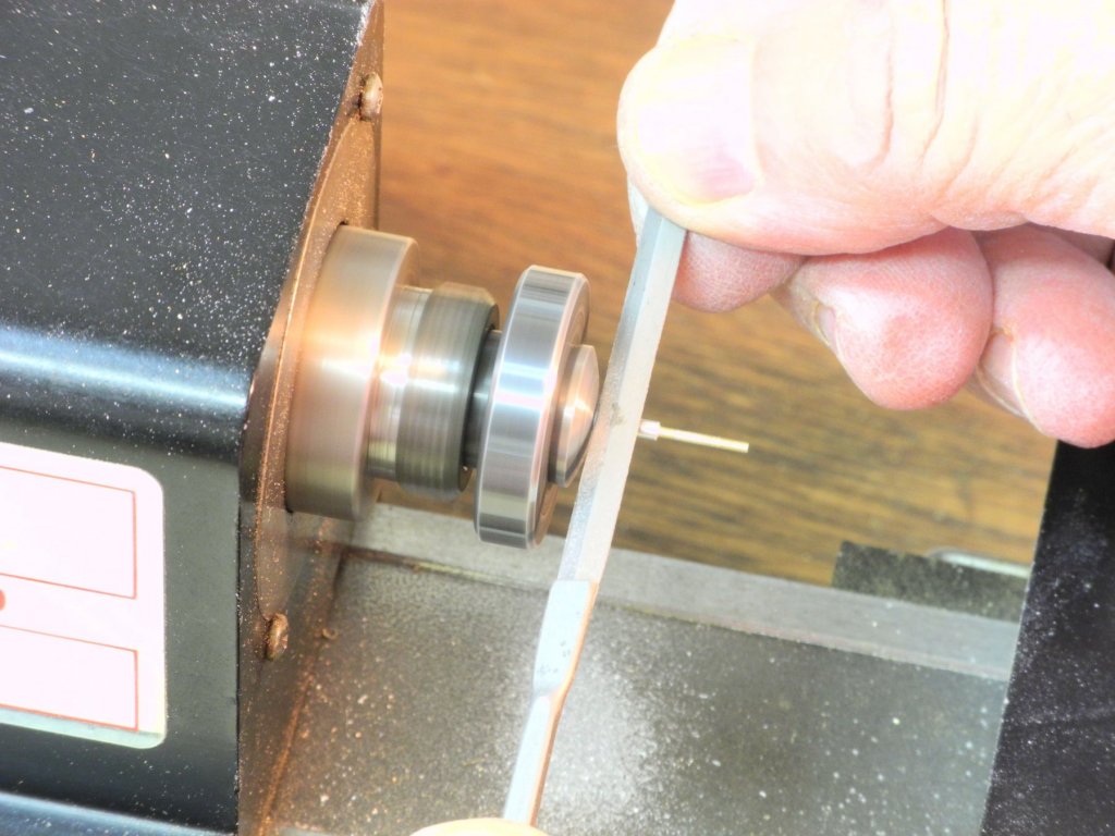
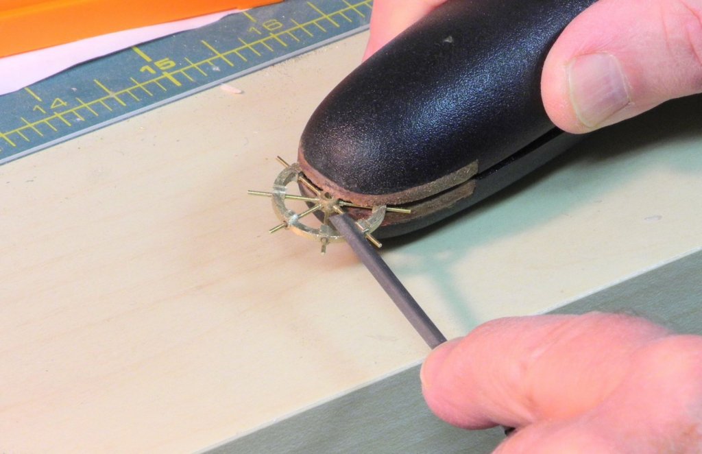
Part 49 – Kathryn’s Dredge Winder Cont’d Progress continues on the dredge winder for Kathryn. The last post addressed the manufacture of the winder drums. These are the main components of the winder, but there are many other pieces that need to be made. The following HAER drawing shows these other components. The clutch assembly is fairly complex, consisting of several different parts. The winder is mounted on I-beams. There are brackets that hold the drums in place, and the drums are encased in protective shells. The shaft for the drive gear reaches from the engine to the front of the winder, and is mounted on a square configuration at the forward face of the winder. Manufacturing the I-beams was a simple matter of reducing the width of a 3/16 square rod, and then milling both sides to form the I shape. The cross pieces of the mount were created by cutting shorter pieces to a 45 degree angle at each end, and then soldering strips on the ends to serve as caps. The following photo shows the components of the mounts laid in place but not yet soldered. The main component of the clutch assembly consists of a barrel shape flattened on the top. The shape was formed on the lathe, and the parting tool was used to cut a separation deep enough for the core of the piece to remain round even after the top is flattened. This allows the parting off of the piece in a later step. The piece was then moved to the mill and the top of the larger cylinder was flattened. The piece was then parted from the stock. A small rod was used to prevent the piece from flying off when parted. The handle of the clutch assembly is connected to the clutch body by a disk that has multiple holes around the outside edge. These disks were created on the rotary table from 3/16” round bar, and were parted off to be .020” thick. The following photo shows the clutch components described above. The clutch handle was made from 1/16 x .020 brass strip. The handle needed to be drilled to take a 1/32” shaft that will attach the handle to the clutch. Drilling was done with a sensitive drilling attachment with the following setup. Weights are attached to the bottom of the clutch handles. These weights were made from 1/8 x .025 stock, and were soldered to the handles using the setup shown in the following photo. The jig was made from Corian. The following photo shows the handles and weights after final shaping of the weights. The disk and a 1/32” rod were soldered to the handles. The tops of the handles incline toward the winder, so the handles needed to be bent. To ensure that both handles were bent at the same place a simple jig was used in the bending. The following photo shows the clutch components dry-fit to a winder drum. An additional part is needed for the clutch assembly. There is a small cap that will sit on top of each clutch body. To make these caps, a piece of stock was milled to shape, and then the middle part was rounded using a rotary tool and files. The following photo shows the stock after shaping but before the two required pieces were parted off. The support for the drive shaft was fairly complex. It was made from 1/8 x .025 brass strip, soldered as a box approximately ¼” square. The forward and rear faces of this support are not full, but are made from some angled pieces. As can be seen in the above photo, one side has slightly sprung as a result of a solder joint failing. This will be repaired before the support is installed. Front and rear brackets are needed for mounting the winder drums, and a bracket is needed for holding the drive shaft on the mount shown above. These brackets were made by drilling appropriate holes in a piece of brass strip, then rough milling to reduce most of the excess, and finally by filing the brackets to the proper shape. The first step in forming the winder’s base was soldering the forward crosspiece to the two runners. A squaring jig was used to ensure that the crosspiece was square. The following photo shows all of the components for the winder that have been made so far. The protective shells still need to be made, and then assembly can begin.


- 878 replies
-
- 19
-

-
Hi Patrick Each time I see Shadow I see more details. It's amazing how much you're able to cram into such a small space. Great work!
-
Thanks Popeye. Lots more parts to make on the winders - I hope to post an update in a day or so.
-
Thanks Russ. I'm going to try to stay with brass for the whole winder configuration (still lots to do) so I hope that blackening will then be consistent.
-
Hi Patrick Besides the quality, the parts from the Willie Bennett kit are generic and don't have some of the details shown in the drawings and photos of Kathryn's winder. I'm going to try to replicate Kathryn's winder as far as possible.
-
Thanks, Mike. There's still a lot of work left on the winder before I need to make the final decision about blackening. The lathe and the milling machine have opened up a lot of modeling possibilities for me - I highly recommend them.
-
Thanks Patrick. The last couple of months have been quite the learning experience - I'm finally starting to feel a little comfortable with my lathe and milling machine.
-
Your metalworking continues to amaze me, Ed. Beautiful work.
- 3,618 replies
-
- 3
-
-
- young america
- clipper
- (and 1 more)
-
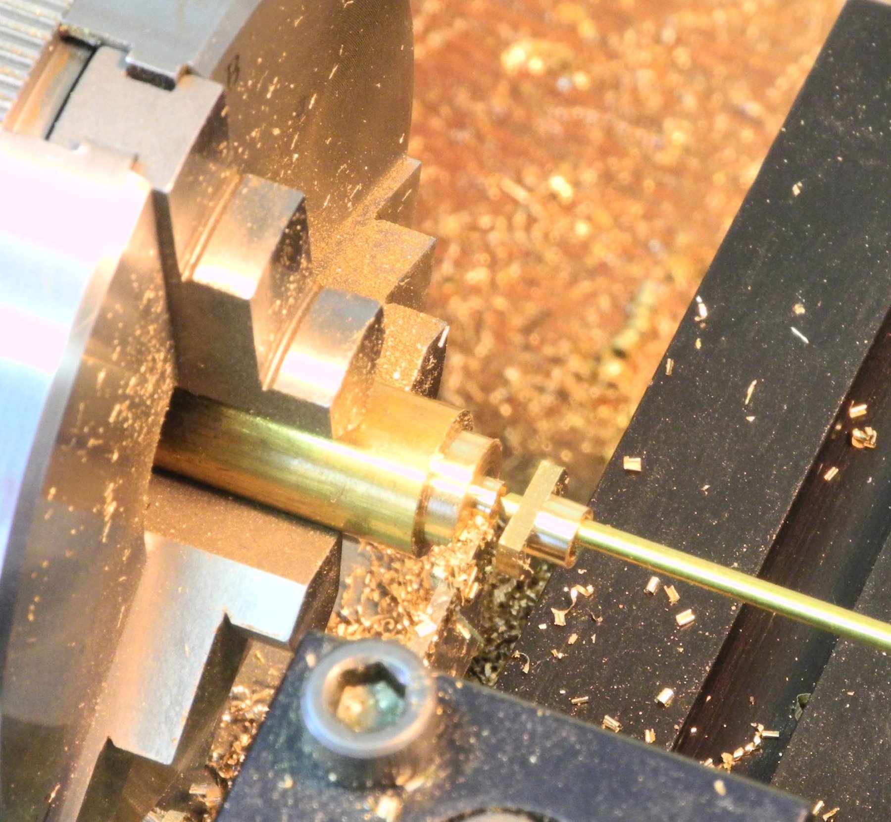
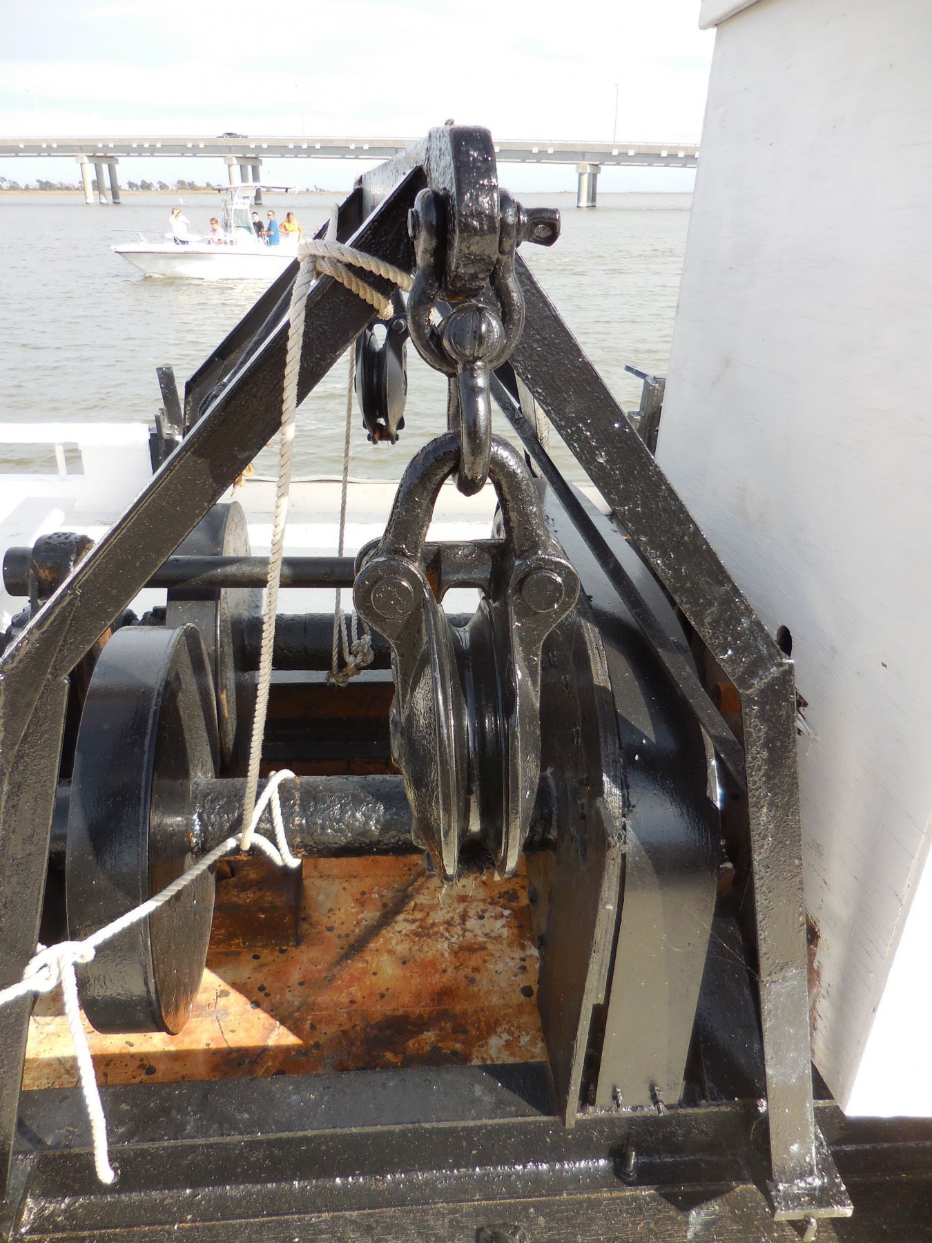
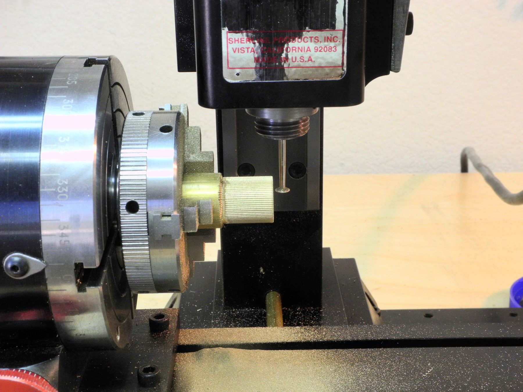
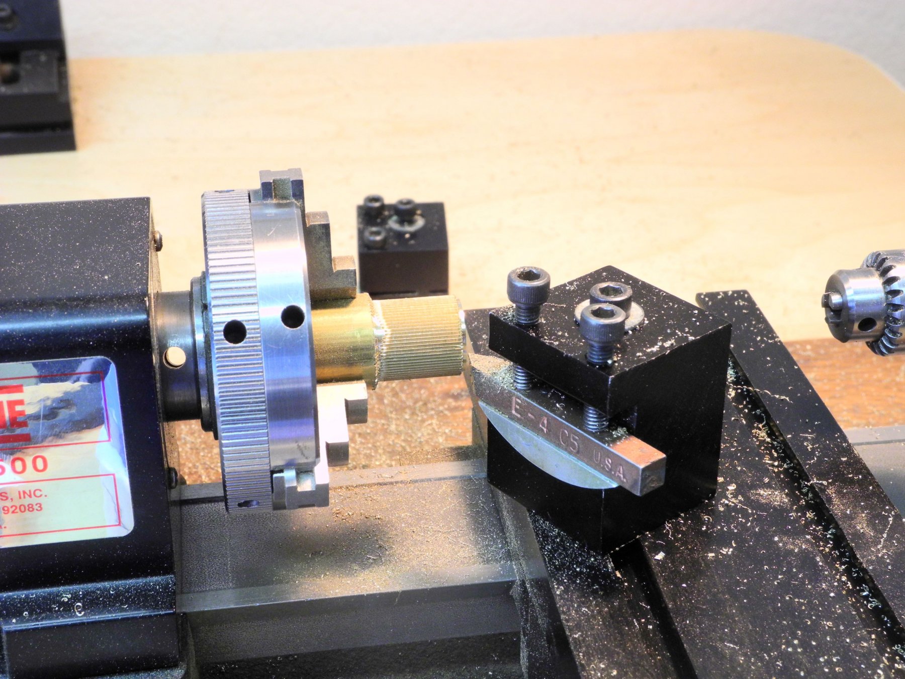
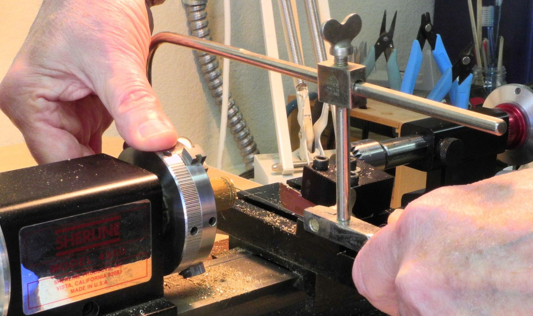
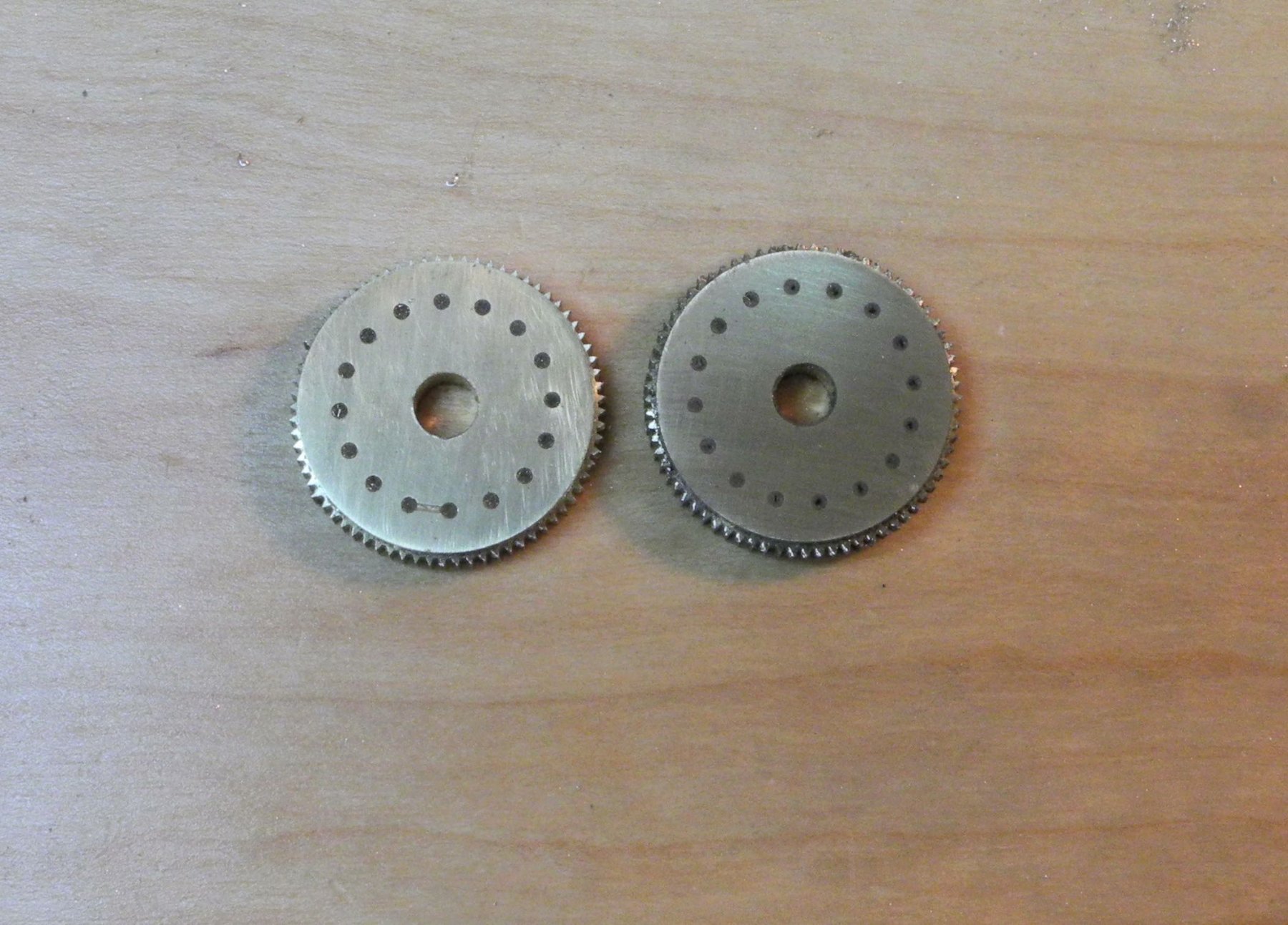
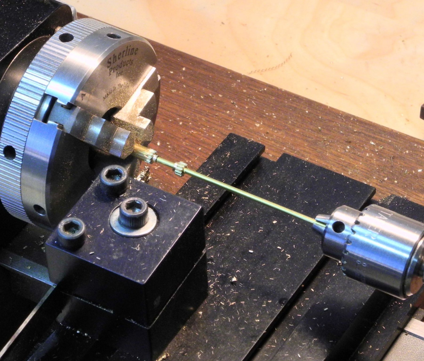
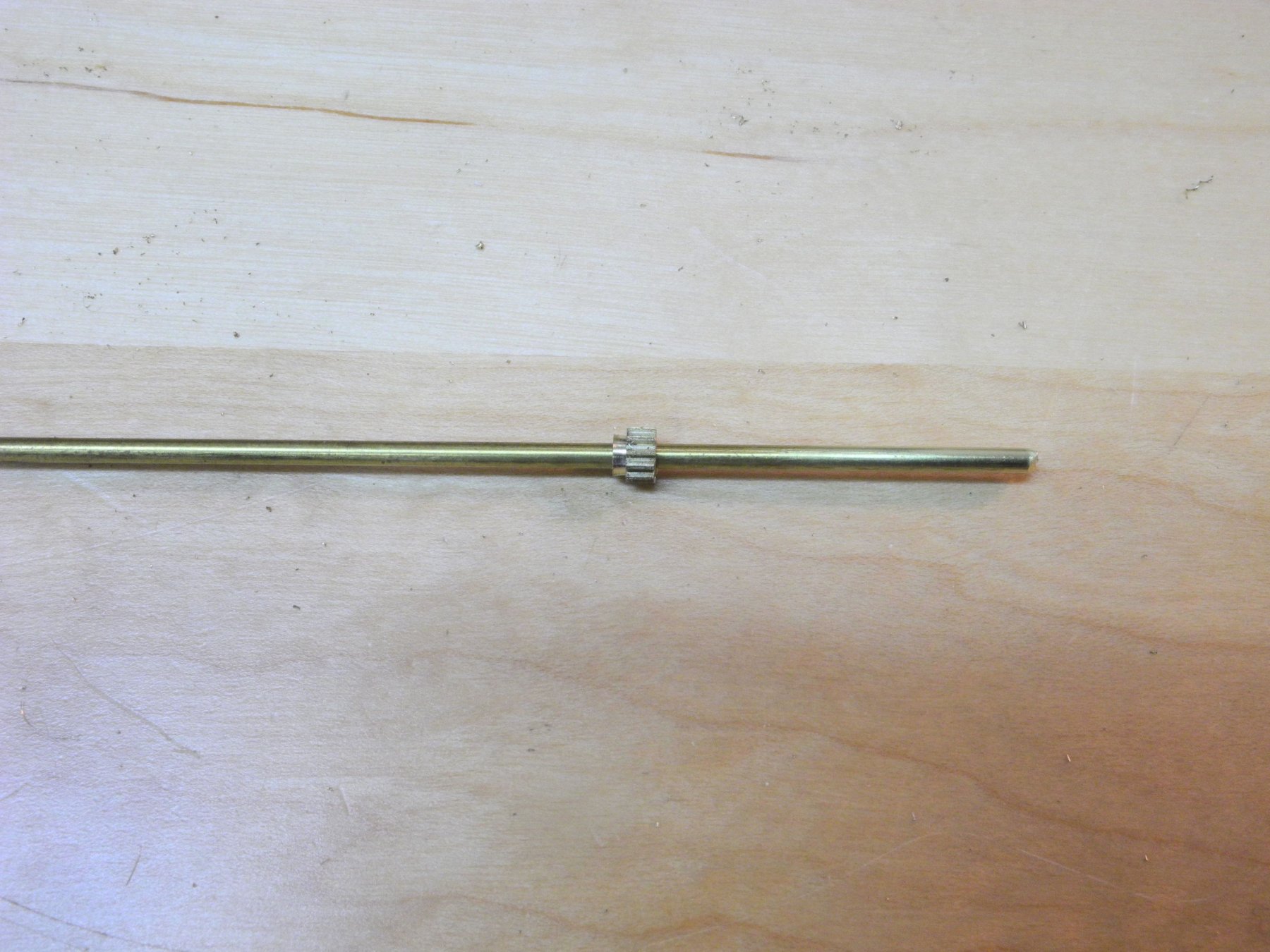
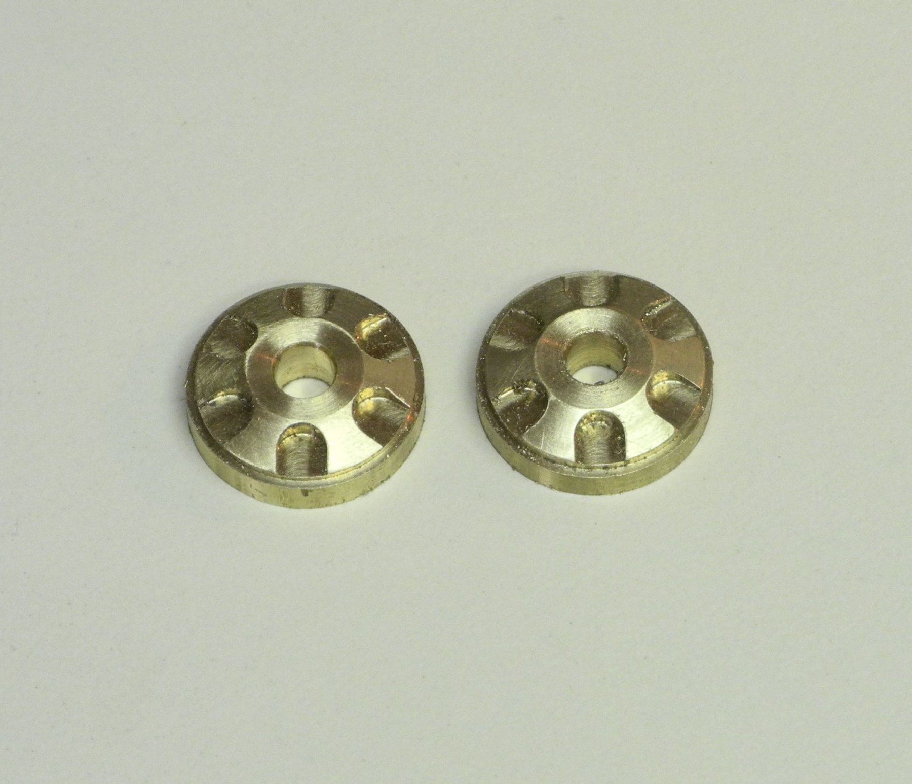
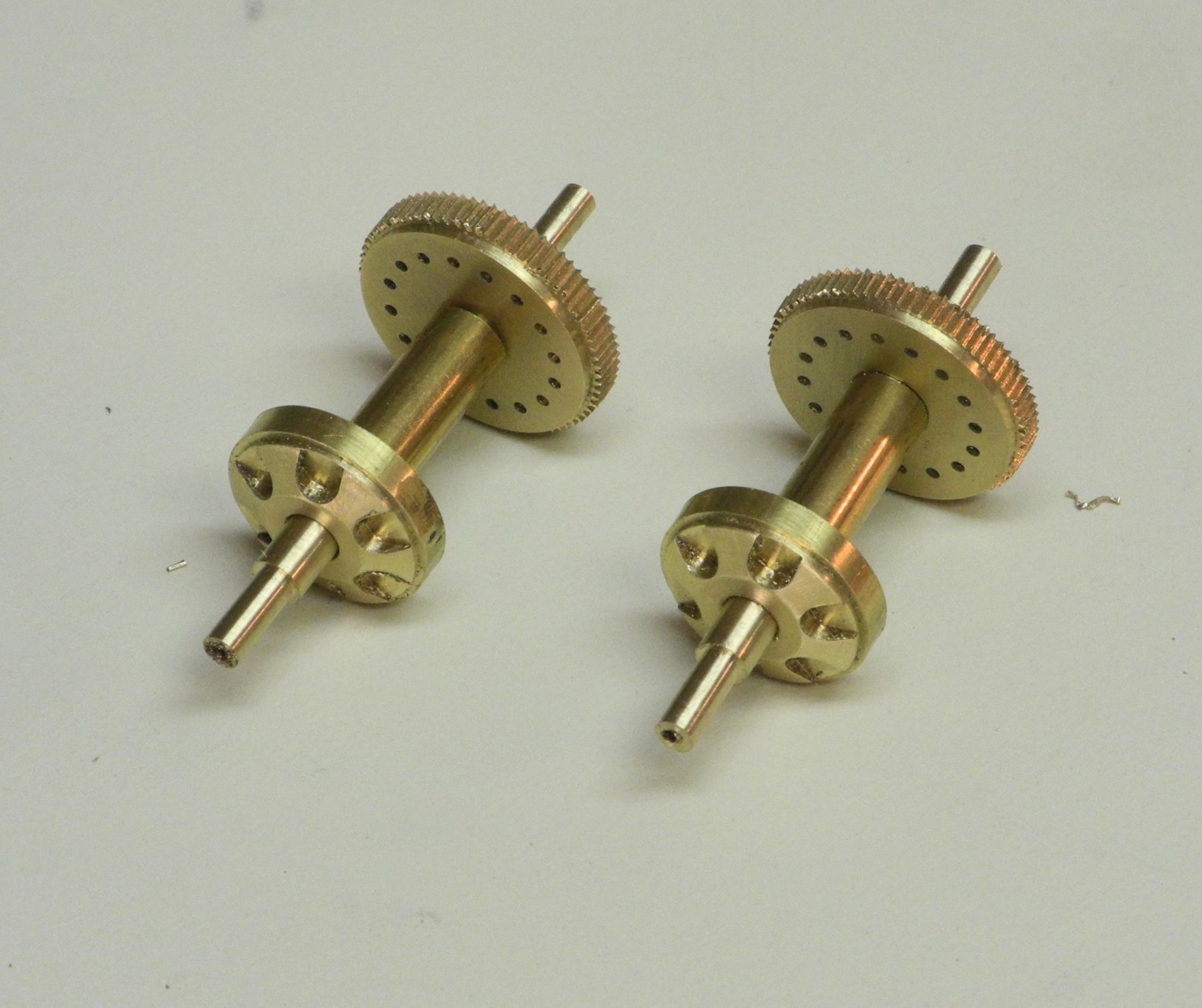
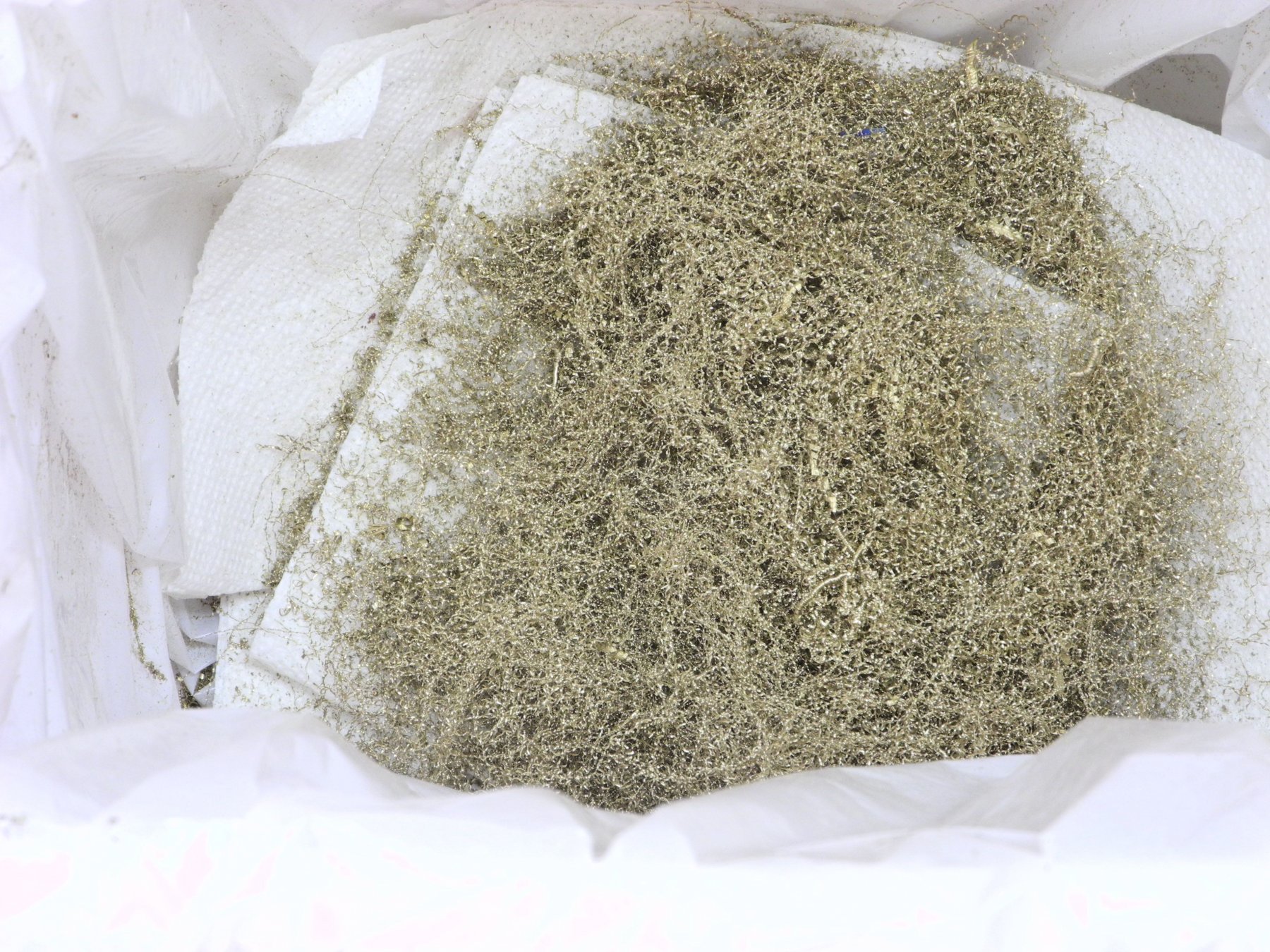
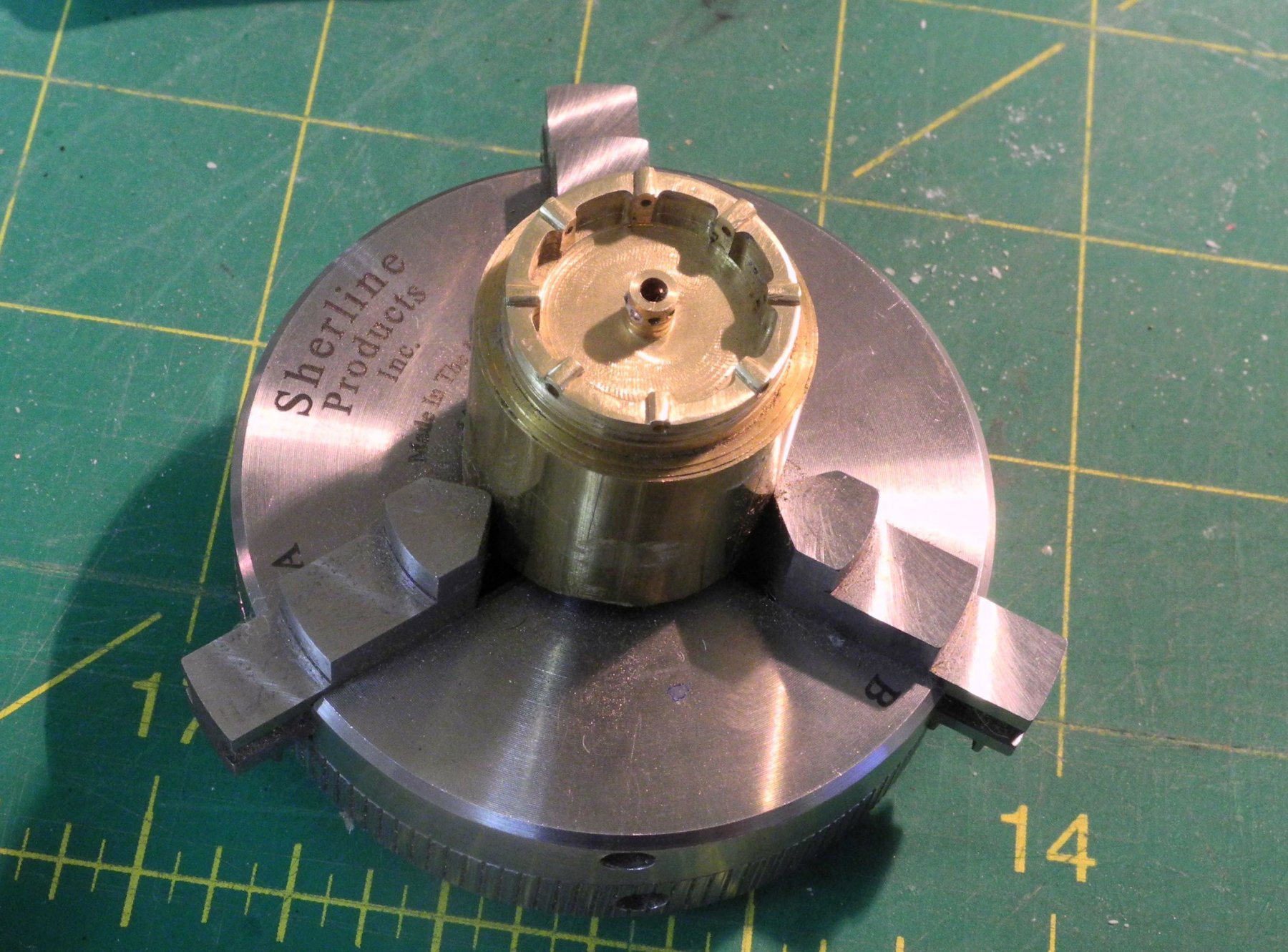
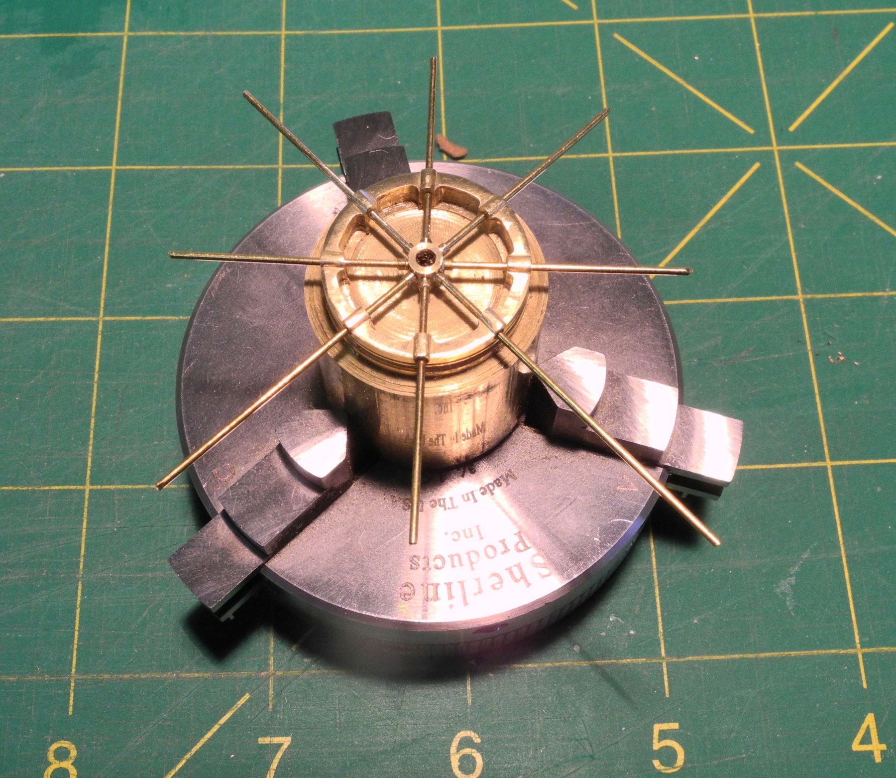
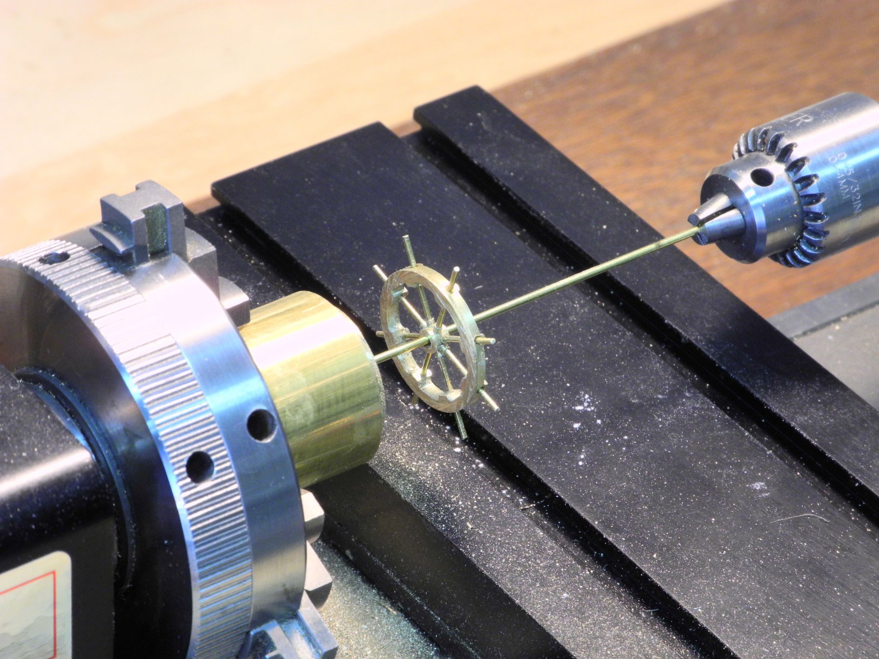
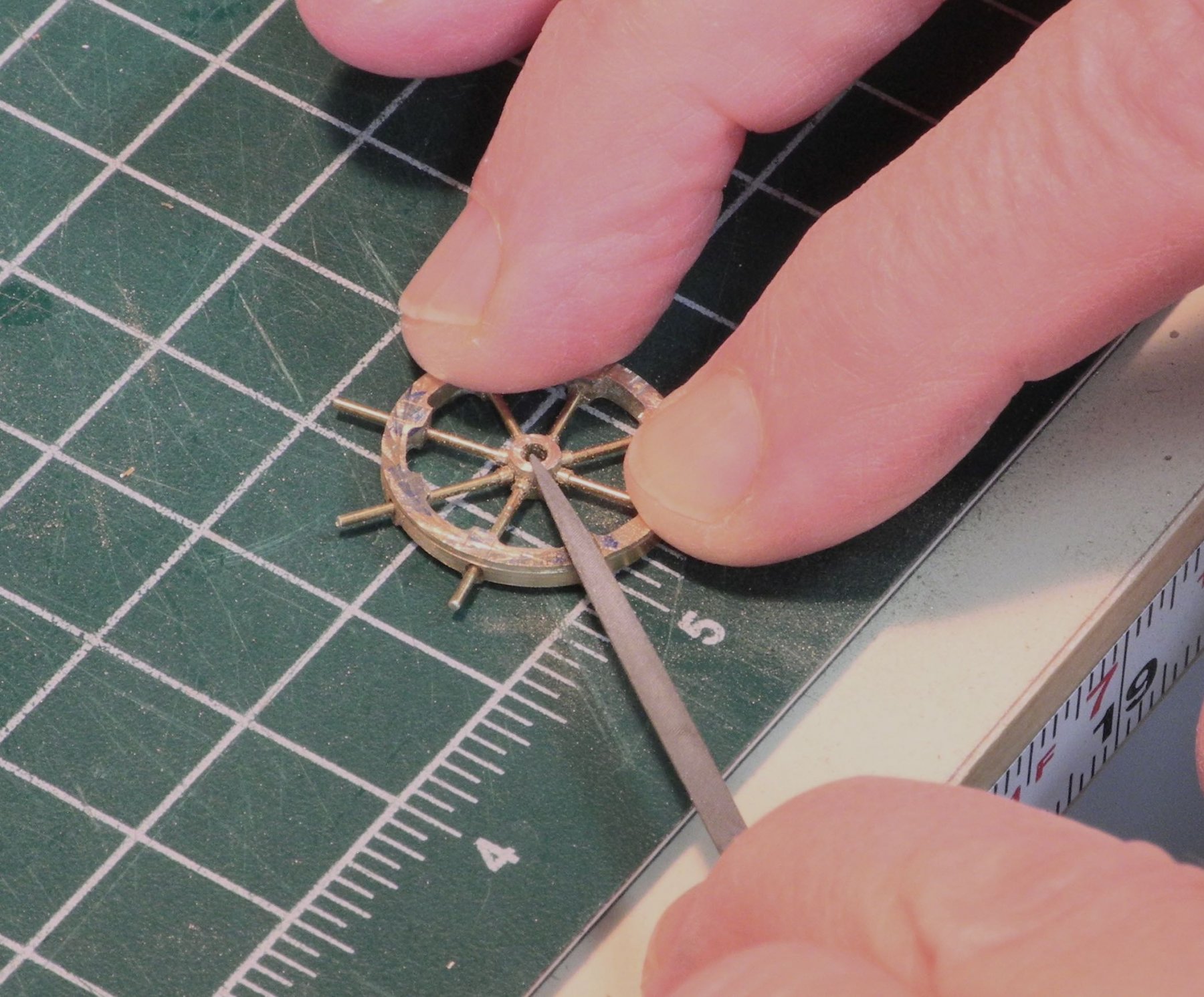
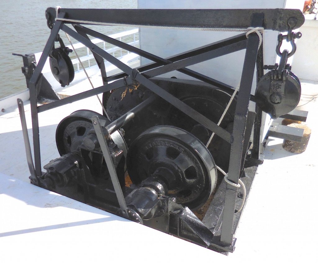
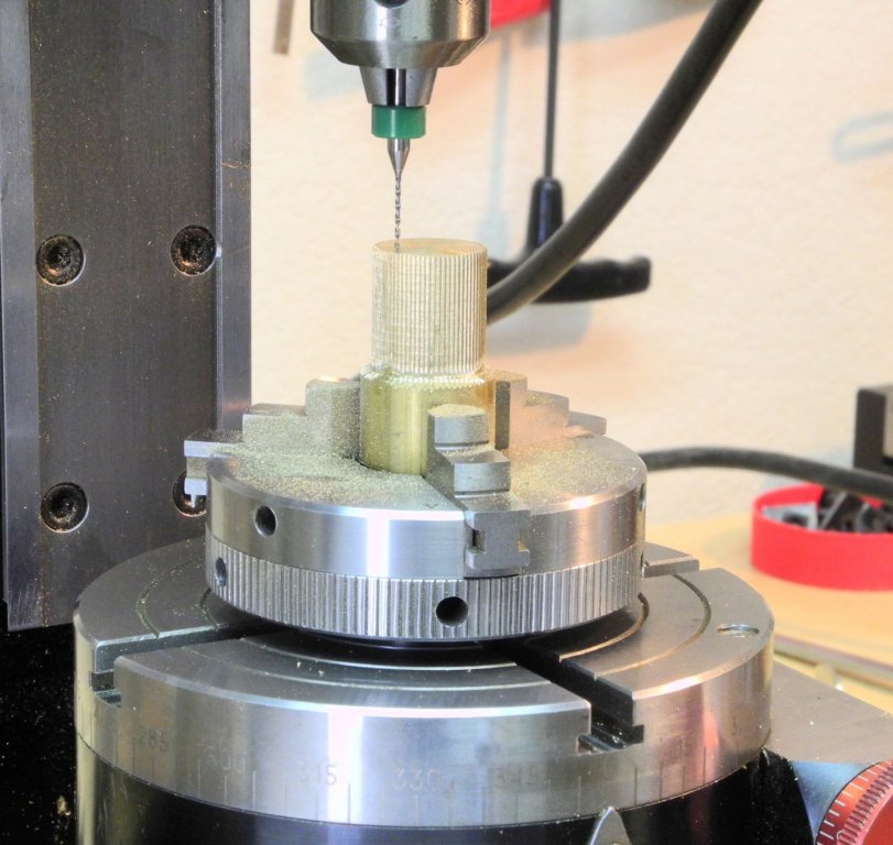
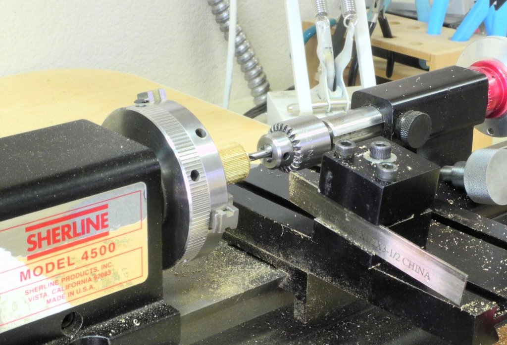
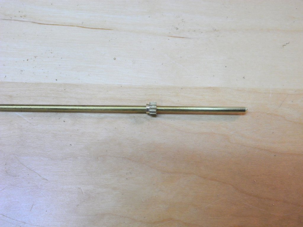
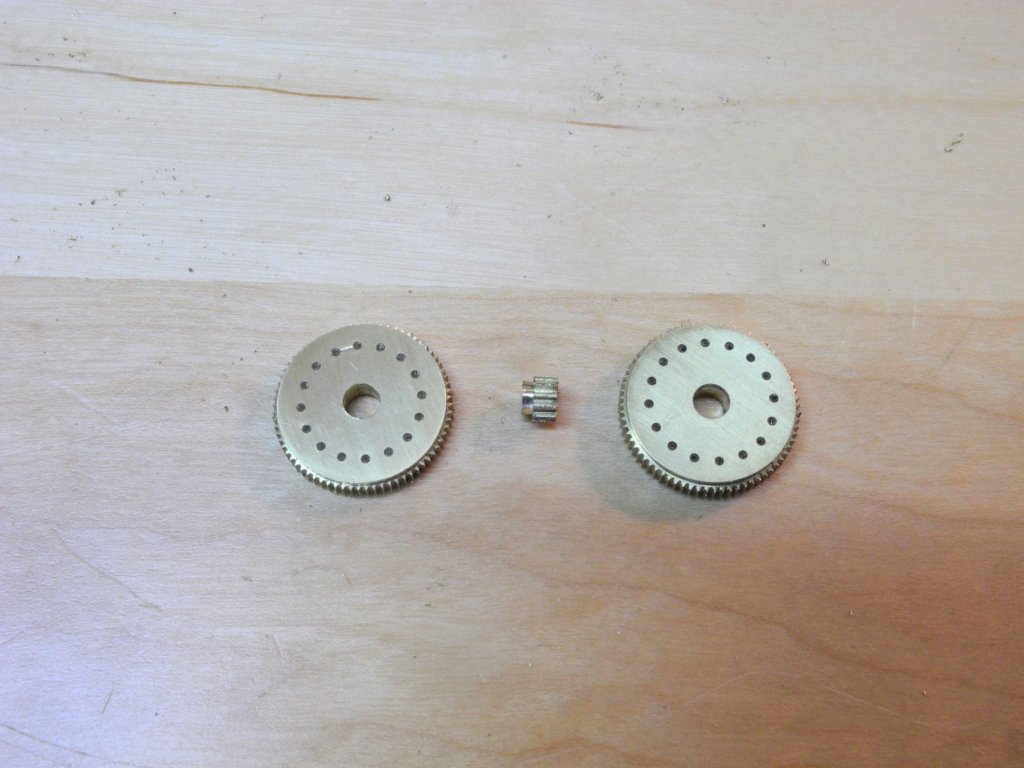
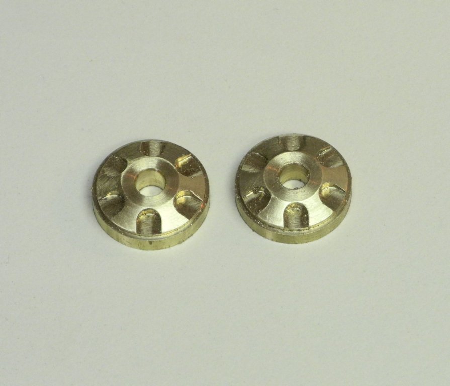
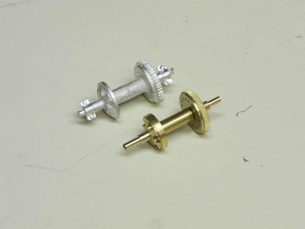
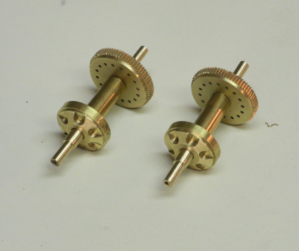
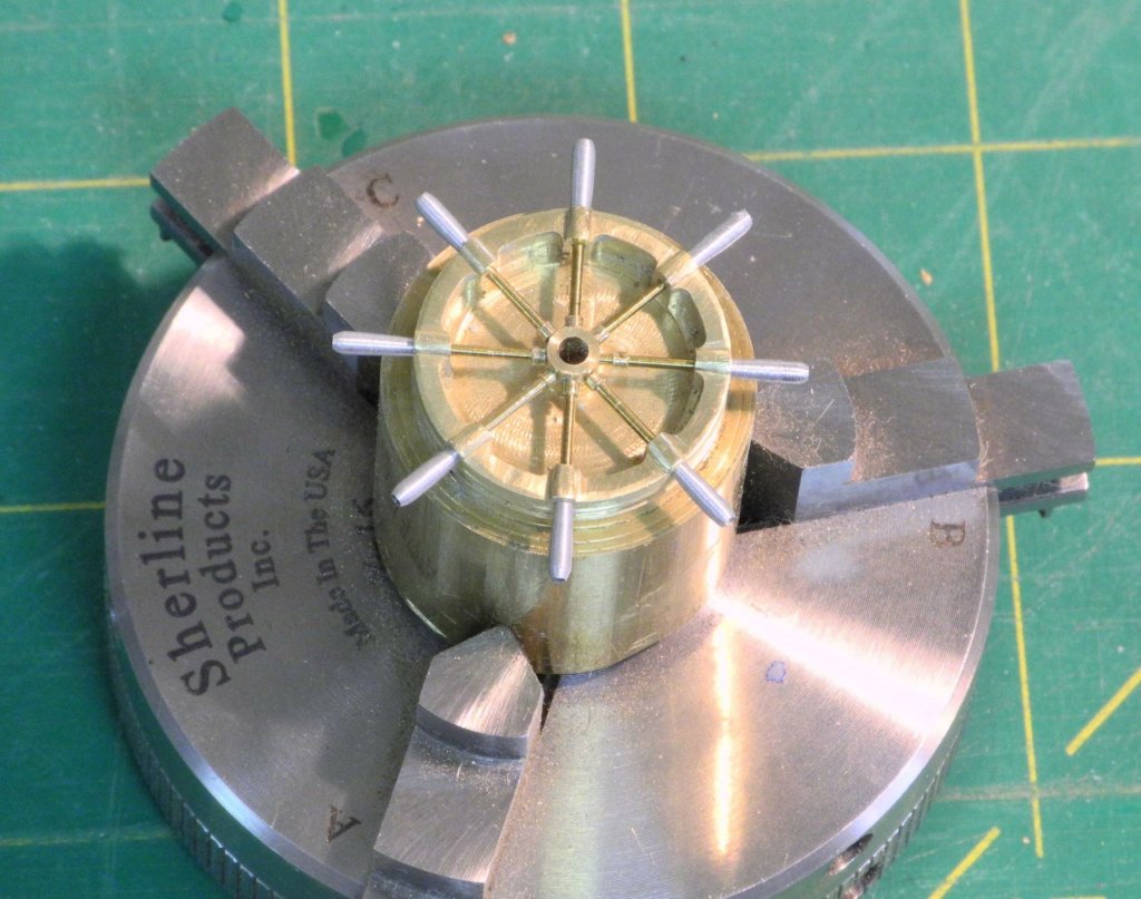
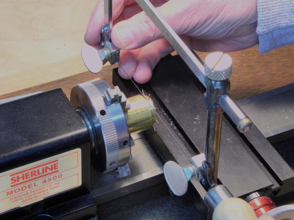
Part 48 – Kathryn’s Dredge Winder At the end of the last post I mentioned that I needed to do some experimenting to determine how to make shackles that are used during the rigging. I did do some experimenting, and I think I have a workable approach, but there’s other work (lots of it!) that needs to be done before rigging can be started. The dredge winders occupy a key position on Kathryn’s deck and are fairly complex, so I decided to make them next. The HAER drawings have a couple of good views of the winders, and I do have some photos I took during my visit to Kathryn last October. The book ‘Working Skipjacks of Deal Island’ also has some good views of Kathryn’s winders in use. The wheels at the rear of the winder assembly are geared and are driven by a small drive gear. The first step was to mill a piece of ¾” brass rod to the proper diameter and to face the rod. This work was done on the lathe. The 3-jaw chuck with the work piece was moved to the rotary table that was set up vertically on the milling machine. A small bit with a diamond disk was mounted using a collet, and was used to cut a small line (.015” deep) every 5 degrees on the surface of the workpiece. This simulated the gears on the wheel. The rotary table was returned to the horizontal position and a #67 drill was used to drill 16 simulated bolt holes around the perimeter of the wheel. The workpiece was returned to the lathe and the small step around the perimeter of the wheel was shaped. The shaft hole in the center of the wheel was drilled using a center drill followed by a succession of small drills until the hole was finished at 1/8”. A groove approximately 1/16” deep was cut in the perimeter of the wheel stock at the appropriate distance from the face of the wheel. This groove was used to guide the jewelers saw that was used to part off the wheel. The geared stock was used to make the second wheel following the same process. The drive gear was made the same way as the geared wheels. A rod was held in the tailstock chuck and through the body of the drive gear to prevent it from getting lost once it was parted off. This completed the gearing on the winder. The front wheels of the winder are smaller than the geared wheels, and have holes cut in a slanted front surface. This slanted surface was made by turning the headstock of the lathe 20 degrees and then facing the end of the stock. The center of the wheel was flattened, and then the workpiece and chuck were installed on the rotary table. The 6 holes were cut using a 7/32 end mill every 30 degrees. A slight indent was cut into the perimeter of the wheel and the wheel was then parted off. A second wheel was made following the same process. Cast winder wheels from a Willie Bennett kit were used as a model during the construction process. With the two sets of wheels and axles completed, the supporting structures will be built next. As with most of my modeling work, there was a lot of trial and error in the learning process for making these wheel sets. I thought it would be interesting to show the amount of swarf created during that process - ugh!. Thanks everyone!


- 878 replies
-
- 24
-
-
Hi Patrick - glad to see some more progress. Shadow looks great, and I'd probably decide to leave her as she is, but I know you'll keep working towards perfection! You're very patient, my friend.
-
Thanks Carl. All glues seem to cause some finishing problems. If I were to do the wheel over I'd try to color the hub, spokes, and spoke nuts before installing them. I don't know if that would be better, but I guess it's worth a try.
-
Hi Peter. I worked on the wheel off and on during December. Trial and error took most of the time (maybe 30 hours) until I learned how to do it right. If I started on another, it would take about 10 hours - 4 hours on the milling machine and the rest mostly hand work. Hi Rich - thanks. But in the enlarged photos I see lots of things I could have done better. Oh well, next time!
-
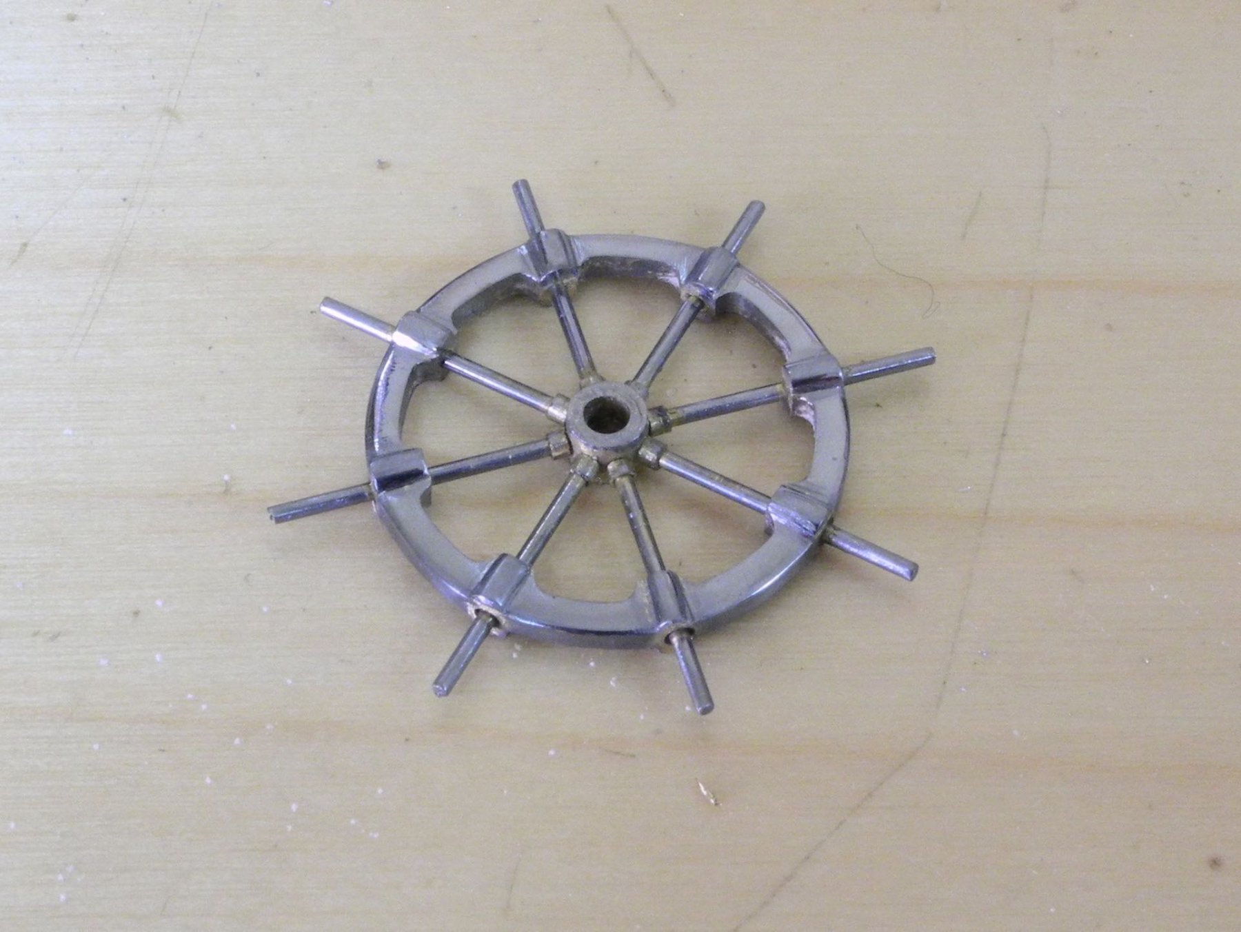
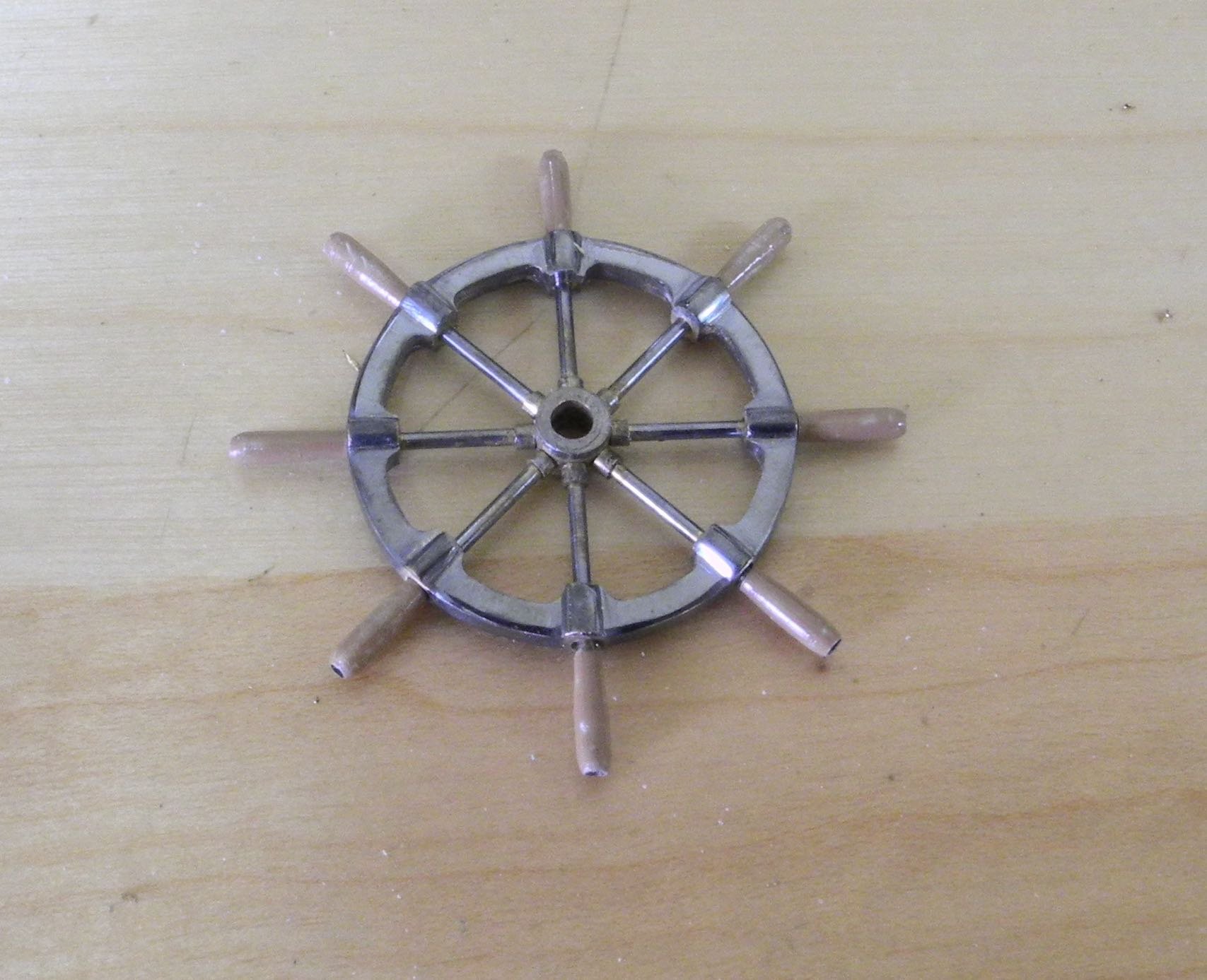
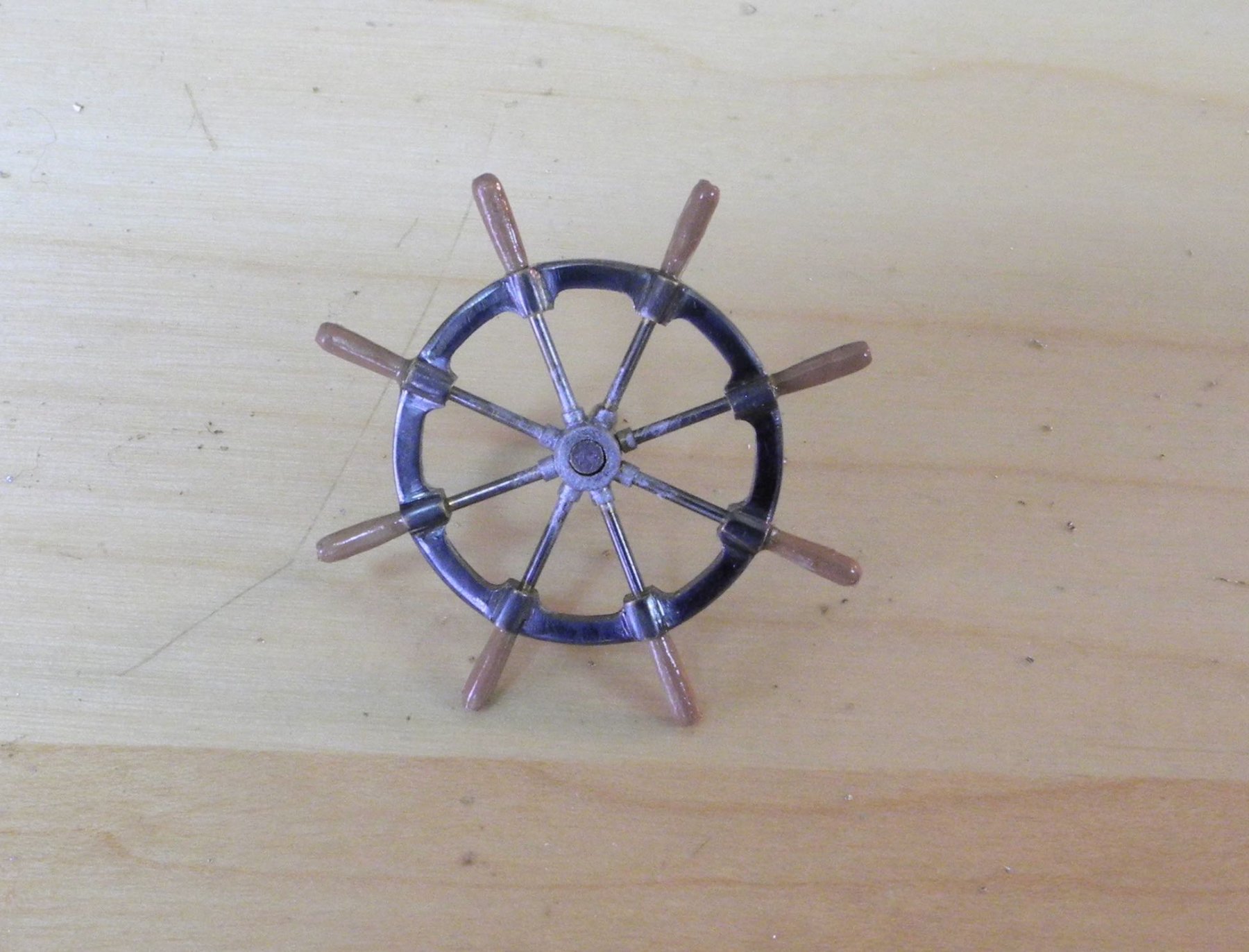
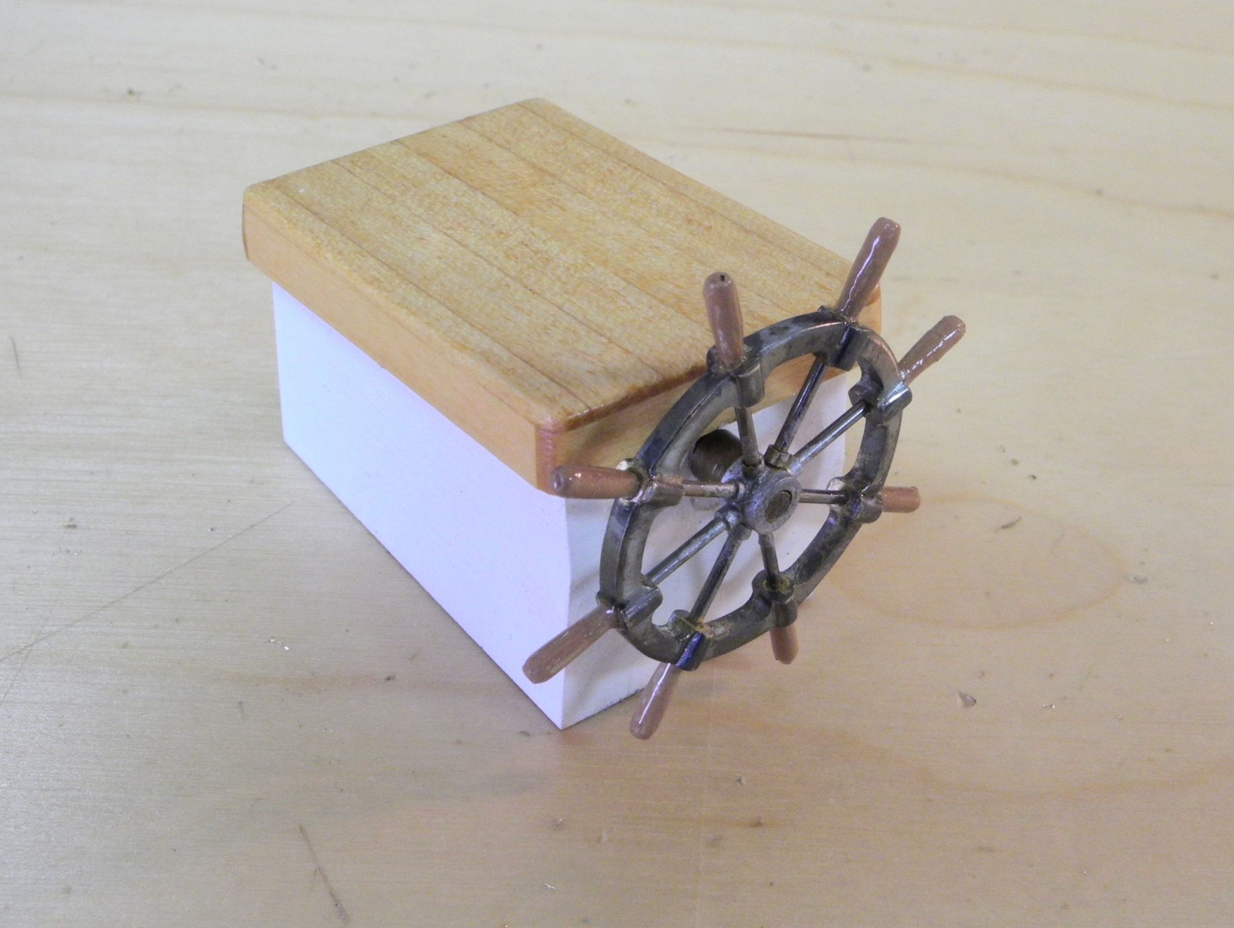
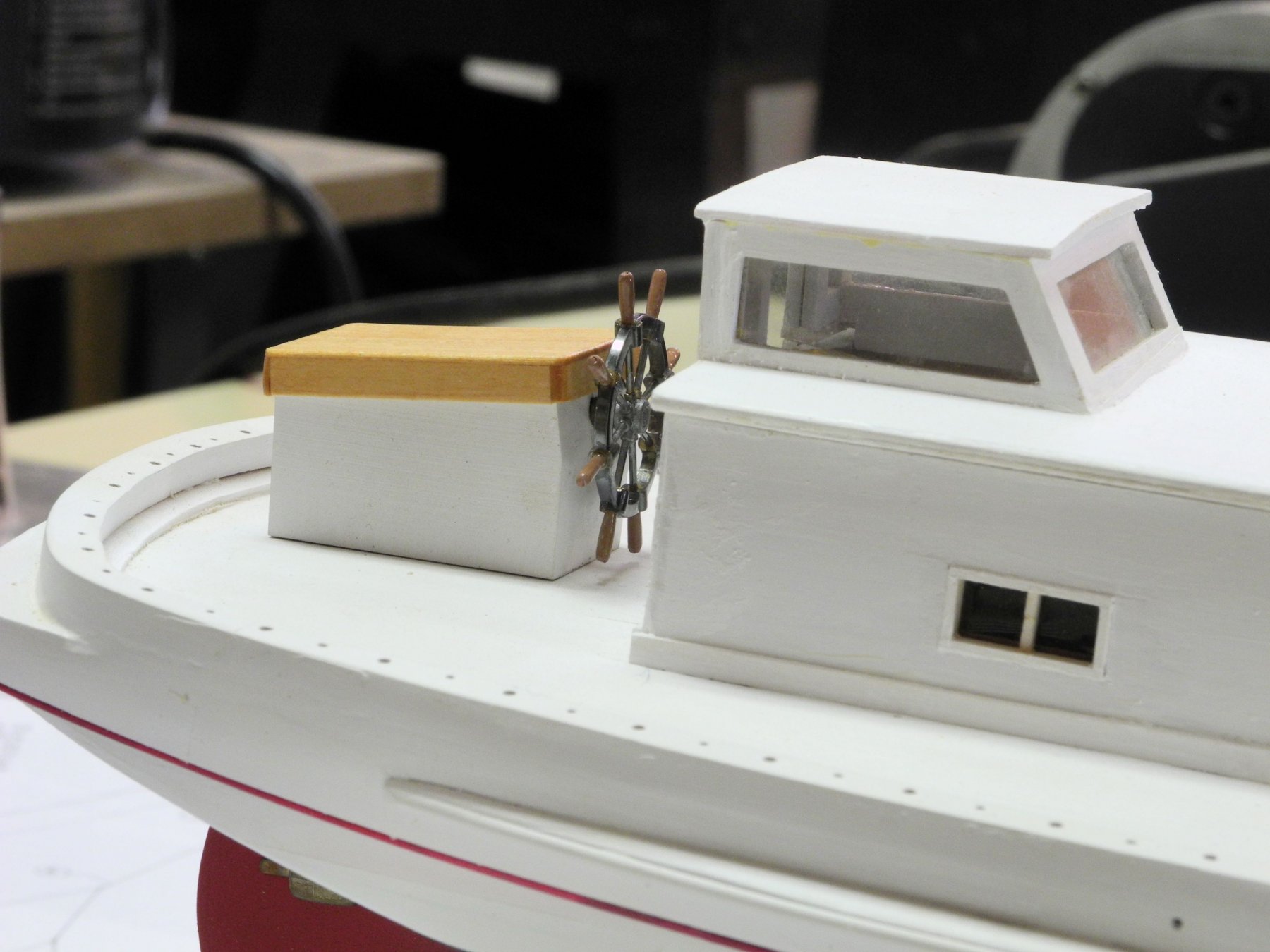
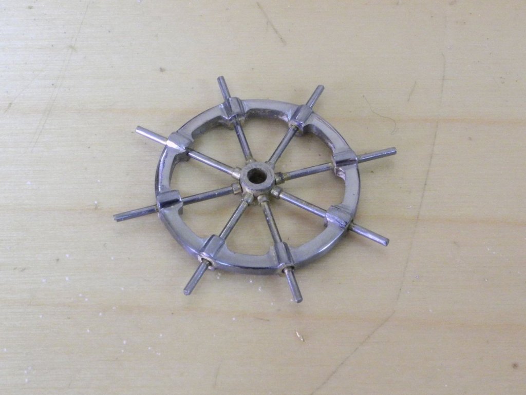
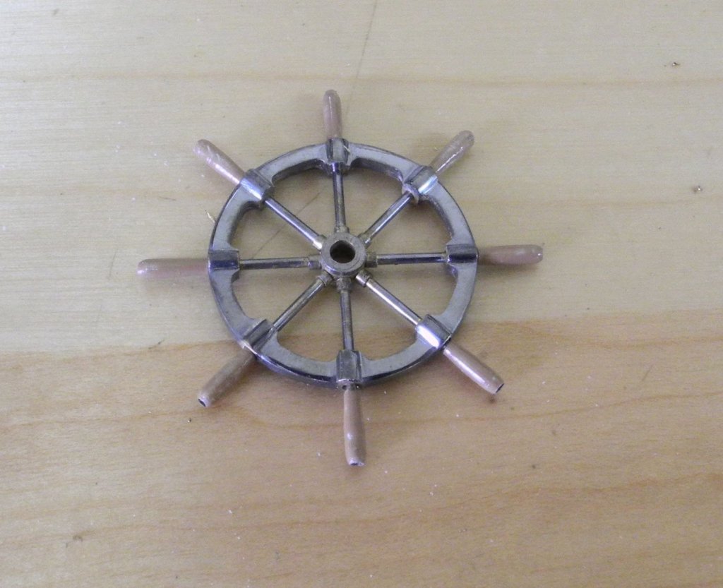
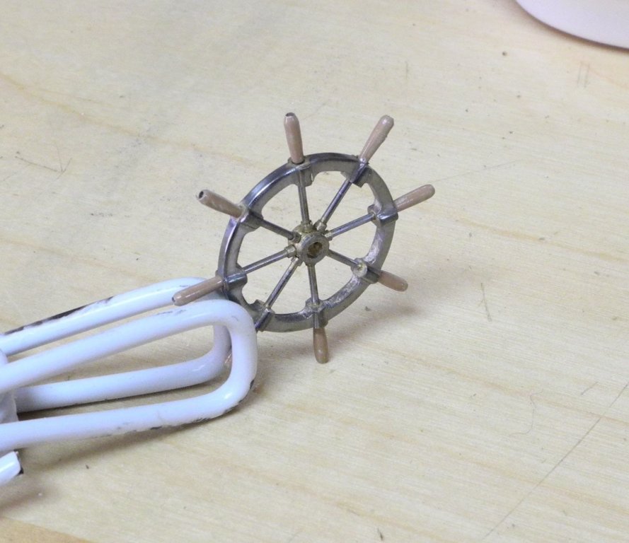
Part 47 – Kathryn’s Wheel cont’d Kathryn’s wheel required some buffing to get rid of the file marks remaining from the shaping exercises. This buffing was accomplished using cloth buffing sheets (similar to emery cloth) from a kit sold by Micro-Mark. The sheets range in grit from 1,200 to 12,000, and I’ve used the kit to get a nicely polished lacquer finish on the base of some bird carvings. It worked quite well on the surfaces of the wheel that could be reached. I’ve experimented with various paints, including Testor’s steel and aluminum colors, but wasn’t happy with the appearance of a painted surface. I found that the Flemish Black from JAX Chemicals gave a very nice finish when diluted with 5 parts water to 1 part of the chemical. The spokes in the area of the spoke nuts didn’t take the finish well, most likely due to the epoxy that was used for the joints. I had tried to clean up the epoxy with isopropyl, but it seems that it didn’t clean up well enough since the brass color still showed. The handles shown in the above photos were painted and temporarily installed to get a feel for how the color (Testor’s wood plus a little dark brown) worked. The handles were epoxied in place, and the openings at the end of the handles were filled in with modeling paste. The color for the handles was darkened slightly and the handles were then touched up. The shaft for the wheel, along with a collar over the shaft, were cut and then darkened with the Flemish Black solution. The wheel was mounted in the steering box, and the box was temporarily mounted on Kathryn’s deck to check its appearance. The steering box needs to be positioned to ensure that the cabin doors can be opened, but before it can be permanently mounted the Sheet Traveler and associated blocks needs to be mounted behind it. That will be the subject of a future post. There are many shackles used in Kathryn’s rigging, and it will require some testing of various approaches to making and installing those shackles before any serious rigging can be done. So it may be a little while before the next post. Thanks everyone!


- 878 replies
-
- 19
-
-
Thanks Joe. I also like the working boats of the Chesapeake, and think they make interesting models. Thanks Druxey. Yeah, lots of labor, especially with the many false starts and re-do's Thanks Popeye. I'm pretty pleased with the wheel. The photos show a lot of things that could have been done better, but it's time to move on to something else.
-
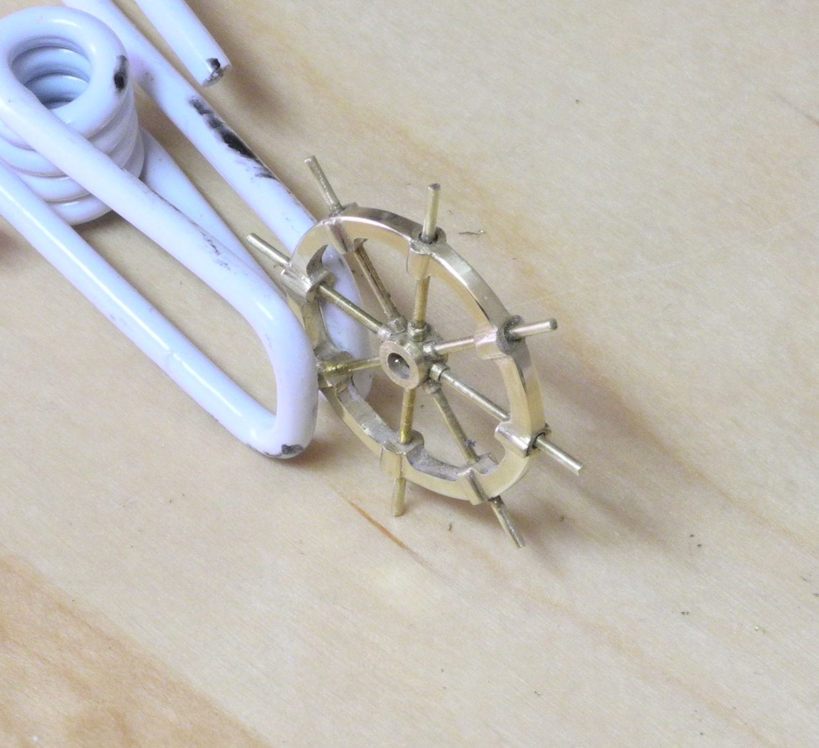
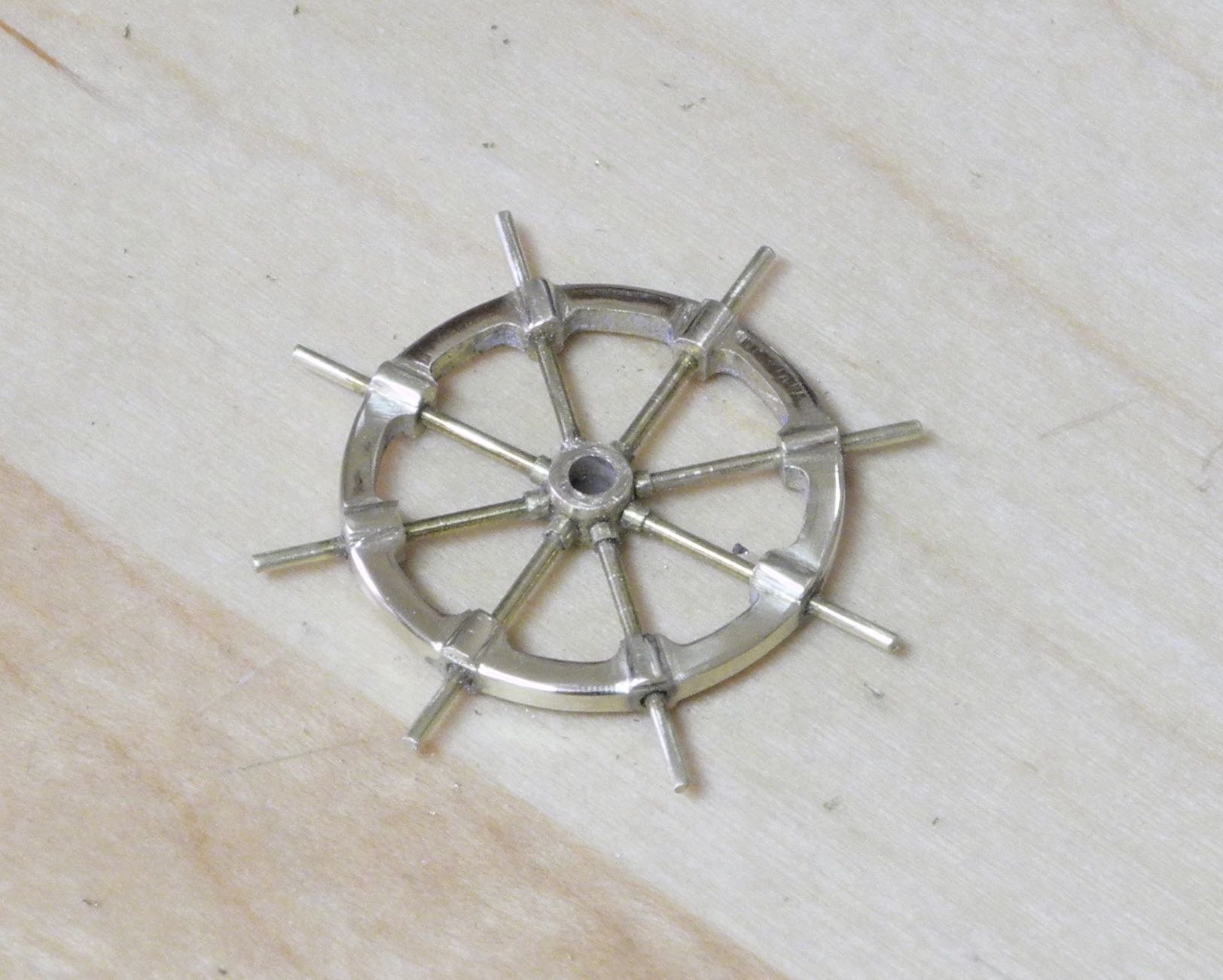
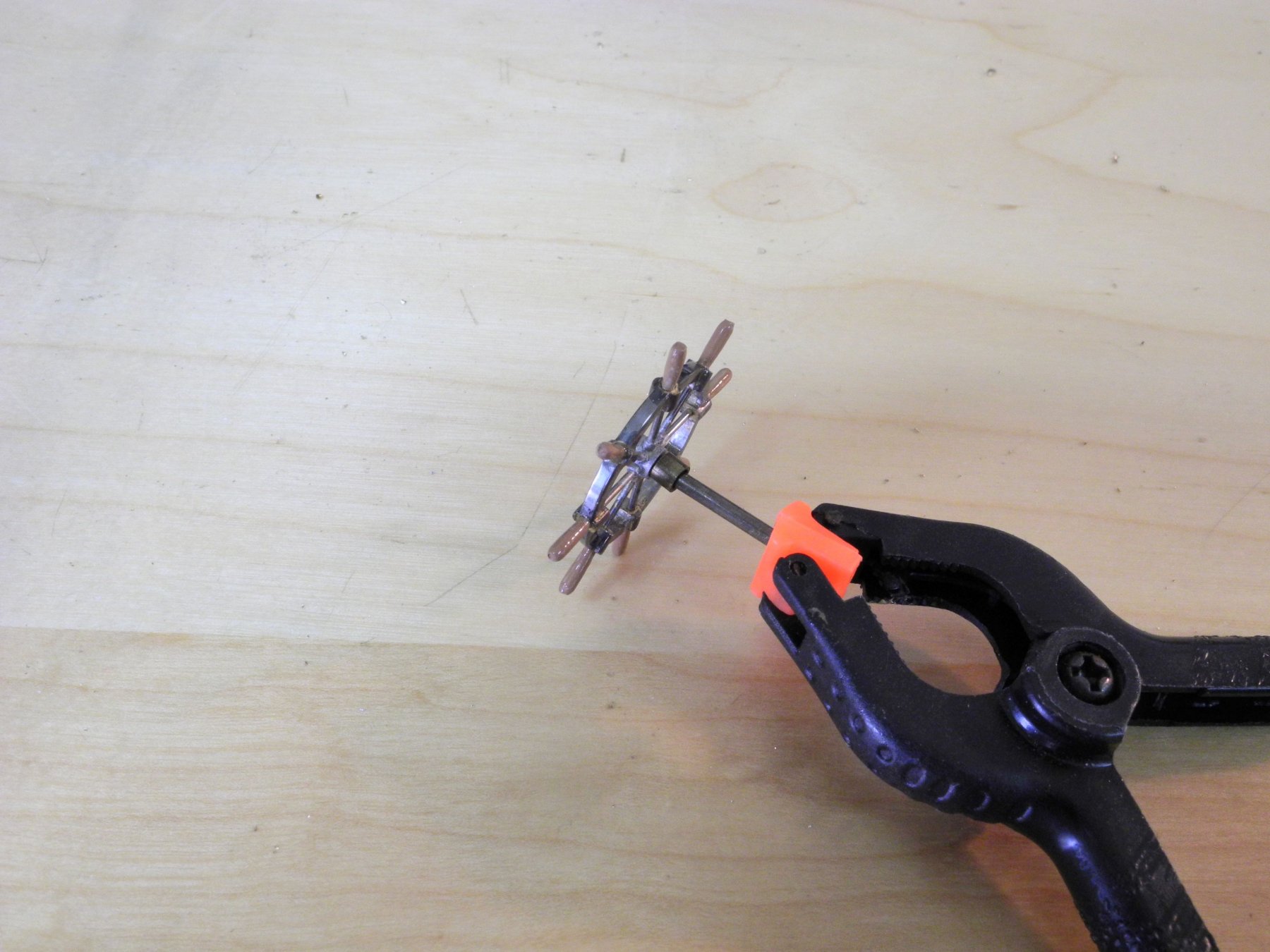
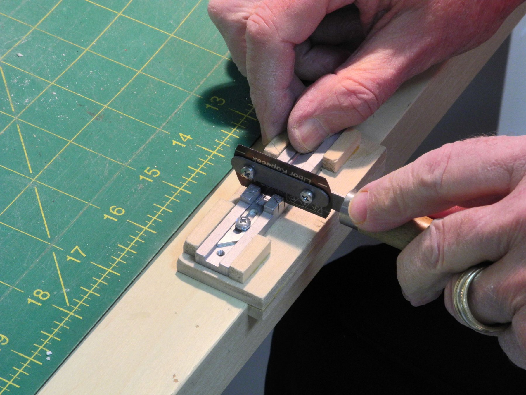
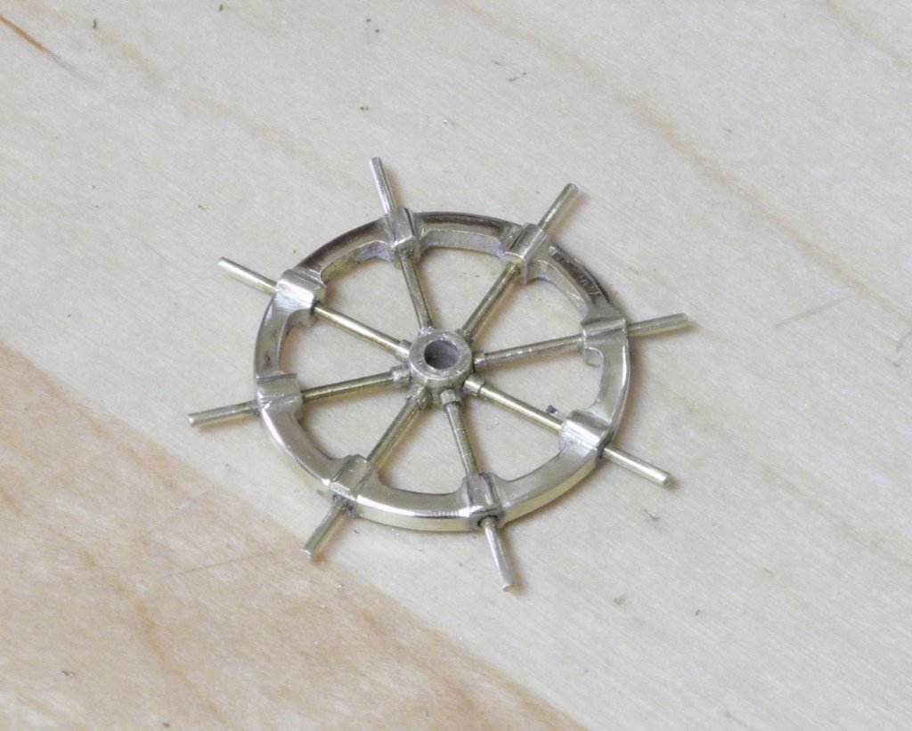
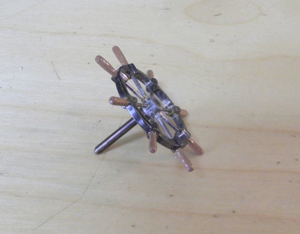
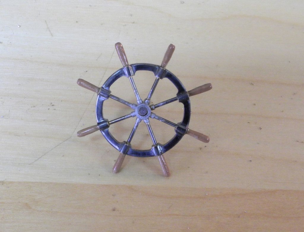
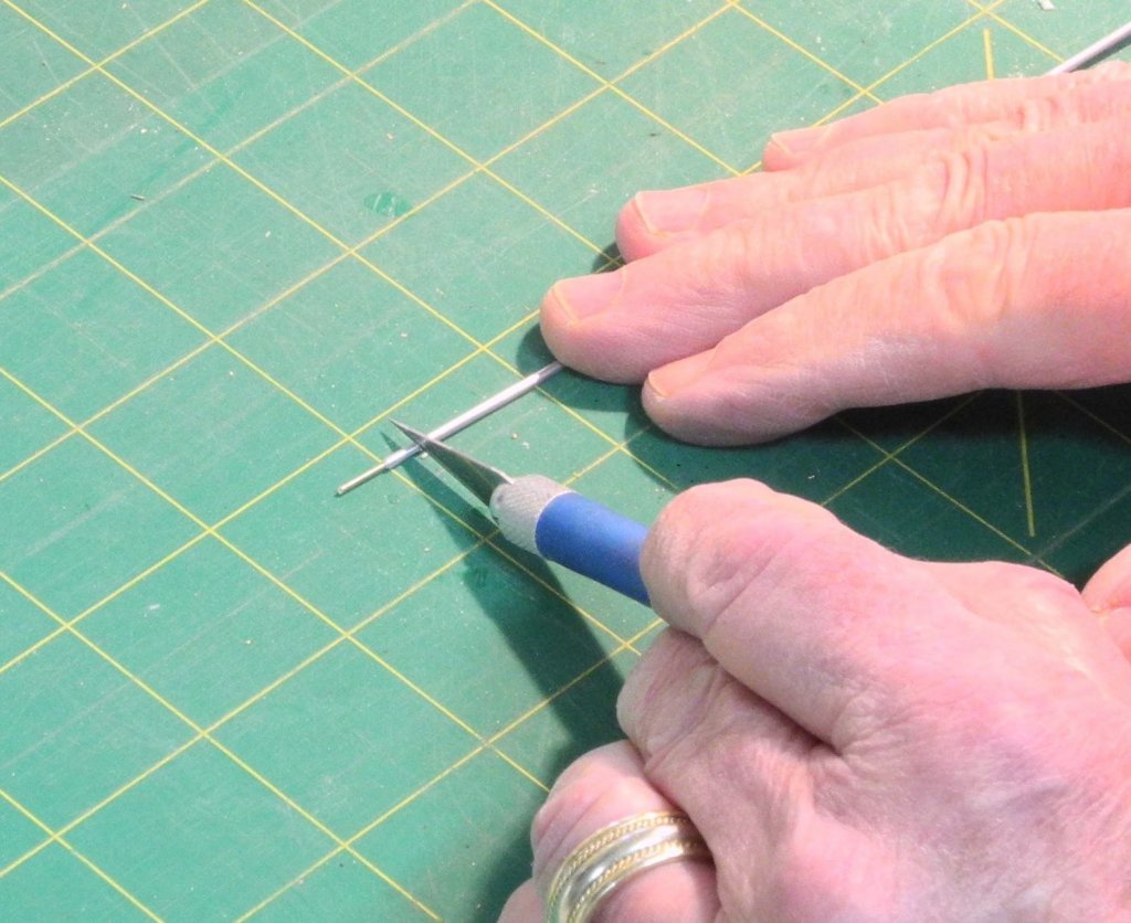
Part 46 – Kathryn’s Wheel cont’d After the milling was completed, there was still quite a bit of work left on Kathryn’s wheel. With the wheel still in the chuck, the spoke seats were filed to the round shape, and the areas between the spoke seats were cleaned up. The nuts that hold the spokes to the hub were simulated using 3/64” brass tube, since this tubing had an interior diameter of 1/32” that would accommodate the spokes. Small pieces approximately 3/64” long were parted from the tube using a micro saw. The burrs that resulted from sawing off the individual piece were cleaned up using a miniature reamer, and the reamer was then used to hold the piece for some light filing. The following photo shows the ‘nuts’ test fitted to the spokes in the wheel. The wheel eventually would need to be parted from the workpiece, and the back side of the wheel would need to be finished. The chuck with the workpiece was returned to the lathe, and a light line was scribed using a pointed lathe cutting tool. This line would be the border of the wheel rim. The parting tool was then used to cut a deeper groove at the high point of the spoke seats for the backside of the wheel. The forward edge of this line would be used as a sawing guide. The handles of Kathryn’s wheel are made of wood. On the model, these handles are a maximum of 1/16” thick and are 3/16” long – too small for drilling and shaping wood. I have some aluminum tubing that measures 1/16” OD and 1/32” ID – perfect for the handles – so I decided to use the aluminum tubing and paint it an appropriate wood color. The first step was to lightly scribe a line for a 3/16” length of tube for the handle. Using a WW collet, the tube was then mounted on the lathe with the line scribed in the previous step used to designate the exposed length. A piece of brass 1/32” rod was inserted in the aluminum tube to prevent it from collapsing. A parallel barrett file was used to shape the handle. Because of the blank side, this file could be rested against the collet without damaging the collet. A hobby knife was used to part off the handle by using slight pressure while rotating the tube. Again, the 1/32” brass rod prevented the tube from collapsing. The following photo shows the wheel with the spokes, nuts, and handles test-fitted. Once all components fit properly, 5-minute epoxy was used to glue the spokes and nuts in place. Excess glue was wiped off using a small artist’s brush dipped in isopropyl. The chuck and workpiece was then mounted back on the lathe to provide a secure platform for parting off the wheel. The lathe was not turned on, it was simply moved by hand while a jewelers saw was used to part off the wheel. A piece of brass rod was inserted in the center hole of the hub to prevent the wheel from falling off once the hub was sawn through. A small triangle file was used to scribe the boundaries for each spoke seat on the unfinished side of the wheel. The rim was then filed to the scribed line to reach the proper thickness, and the spoke seats were rounded to the final shape. The clamp shown in the prior photo is a jewelers ring clamp. The jaws on either end are leather lined, and holding pressure is achieved by pushing a wedge into the end opposite the workpiece. The wheel is essentially completed, but still needs final finishing, painting, and mounting – this work will be posted in the next day or so. Thanks everyone for the ‘likes’ and comments.


- 878 replies
-
- 21
-